1
IEEE 1394 Camera Series (IM-30/IM-100)
User’s Manual
Manual Version: 2.1
Revision Date: April 30, 2008
ICP DAS CO., LTD.
www.icpdas.com
Table of Contents
1
Introduction.................................................................................. 4
1.1
1.2
1.3
1.4
1.4.1
1.4.2
1.4.3
1.4.4
1.4.5
1.4.6
Features .........................................................................................4
Applications....................................................................................4
System Requirement......................................................................4
Function Descriptions.....................................................................5
AOI (Area of Interest) .....................................................................5
Test Pattern ....................................................................................6
Mirror Image...................................................................................7
Gain and Brightness.......................................................................8
Lookup Table ................................................................................10
Shutter (Exposure) .......................................................................12
1.4.7 Input/Output .................................................................................13
1.4.8 External Trigger ............................................................................15
1.4.9 Strobe Control ..............................................................................17
1.5
Spectral Response .......................................................................18
1.6
Integrate Enabled Signal Timing ..................................................19
1.7
Benchmarks .................................................................................20
2
Hardware Reference.................................................................. 21
2.1
MAVIS IM-30/IM-100 ....................................................................21
2.1.1 Camera Specification ...................................................................21
2.1.2 Camera Interface .........................................................................22
2.1.3 Standard Package Contents.........................................................22
2.2
Optional Accessory.......................................................................23
2.2.1 1394 Dual-port Card: IOI-4601-21................................................23
2.2.2 1394 Latch Cable: CA-1394-45.....................................................23
2.2.3 1394 Repeater: 1394R3B .............................................................24
3
Installation Guide....................................................................... 25
3.1
Hardware Installation....................................................................25
3.1.1 IPC/PC Platform............................................................................25
3.1.2 Notebook PC / PCMCIA Socket ....................................................27
3.2
Driver Installation..........................................................................29
3.2.1 For Visual Studio (VC/VB/BCB/VC#.NET) Users ..........................29
3.2.2 For LabVIEW Users ......................................................................33
4
EZView Utility............................................................................. 34
4.1
Overview ......................................................................................34
-2-
4.2
5
EzVIEW_Fly Utility ..................................................................... 42
5.1
5.2
5.3
5.4
6
Overview ......................................................................................42
Configuration................................................................................43
Help – About EzVIEW_Fly............................................................47
Tool Icons .....................................................................................47
Function Library ........................................................................ 50
6.1
6.2
6.3
6.4
6.5
6.6
6.7
6.8
6.9
6.10
6.11
6.12
7
8
Component Description................................................................35
List of Functions ...........................................................................51
Programming Flowchart ...............................................................52
Camera Management...................................................................56
Camera Acquisition ......................................................................59
Camera Configuration ..................................................................67
Digital Input/Output.......................................................................75
External Trigger ............................................................................82
Strobe Control ..............................................................................87
Lookup Table ................................................................................93
AOI (Area of Interest) ...................................................................97
Advanced Features ......................................................................99
Sample Programs ......................................................................101
6.12.1 Sample program for VC++/BCB/C#.NET ..................................101
6.12.2 Sample program for VB.............................................................102
Mechanical ............................................................................... 103
Appendix .................................................................................. 104
8.1
8.2
8.3
Standards Compliance ...............................................................104
Glossary .....................................................................................105
Revision History .........................................................................107
Warranty Policy.............................................................................. 108
ICP DAS Worldwide ....................................................................... 109
-3-
1 Introduction
MAVIS is a new and exciting vision product line from ICP DAS, designed specifically for
industry machine vision applications. The MAVIS IM series is designed to meet or exceed
IEEE 1394 standards, while offering industry leading VGA resolution, high-performance
frame rates, and a competitive price point! The Mavis IM30 offers 30fps for low-cost
progressive-scan inspection applications, while the Mavis IM100 can offer up to 100fps, in
full resolution for advanced high-speed inspection applications.
1.1 Features
z
Digital IEEE1394 video output
z
Progressive-scan for on-the-fly applications
z
Acquisition speed up to 100fps in full resolution
z
Build-in 8MB memory buffer
z
Flexible electric exposure control
z
Robust external trigger I/O interface supported
z
Free SDK API for VC, VB, BCB and C#.NET
z
Compatible with NI-IMAQ-1394
z
Driver supports Windows2000/XP
1.2 Applications
z
Semiconductor
z
Component inspection
z
Manufacturing quality control
z
Food and beverage inspection
z
Microscopy and medical imaging
1.3 System Requirement
To ensure seamless operation, ICP DAS recommends that your system meets
the minimum requirements below:
¾
Platform: Pentium III 800MHz CPU, 256MB DDRAM or above.
¾
VGA display: AGP 4X or above.
¾
Display setting: 800 x 600 resolution or above.
¾
32-bit OS only:
if using Windows 2000, please upgrade to Service Pack 4 or above.
If using Windows XP, please upgrade to Service Pack 2 or above.
**Please refer 1.7 Benchmark for system limitation information.**
-4-
1.4 Function Descriptions
In this section, we will outline the MAVIS IM-30/IM-100 camera control functions.
To ensure proper implementation, please carefully review the, limitation
parameters and formula calculations, listed below.
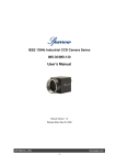
1.4.1 AOI (Area of Interest)
The AOI (Area of Interest) function allows users to select an area of interest,
for the camera’s CMOS array to specifically read, display, and transmit.
Figure 1-1: AOI (Area of Interest)
The AOI function will also enhance camera acquisition speed, however
users must still consider the following factors:
(1) The amount of time it takes to transfer a captured image from the
CMOS sensor to the frame buffer.
(2) The amount of time it takes to transfer an image from the frame buffer
to the PC via 1394 bus.
(3) The camera exposure time setting.
Below, are three formulas that can help you to calculate the maximum
frame rate, while using the AOI function. Please note that the lowest value
will determine the maximum frame rate for the given AOI.
Formula 1: Max. Frames/s = 1 / (((AOI High + 2) x 15.28us) + 15.28us)
Formula 2: Max. Frames/s = 1 / (Packet per frame x 125us)
Formula 3: Max. Frames/s = 1 / (exposure time in us + 28us)
For example, if your AOI is set for 200 columns wide and 240 rows high,
and exposure time is set for 1000us. Also the packet per frame with the
-5-
current settings is 5.
Formula 1:
Max. Frames/s = 1 / (((240 + 2) x 15.28us) + 15.28us)
Max. Frames/s = 269.2
Formula 2:
Max. Frames/s = 1 / (5 x 125us)
Max. Frames/s = 1600
Formula 3:
Max. Frames/s = 1 / (1000 us + 28us)
Max. Frames/s = 972.76
By using the calculations above, the AOI for this particular scenario can be
calculated at 269 frames per second.
1.4.2 Test Pattern
The MAVIS IM-30/IM-100 series cameras offer an internal generated test
pattern for testing camera transmission. The test pattern will show a gray
bar running diagonally, moving upwards at 1pixel/frame.
Figure 1-2: MAVIS IM-30/IM-100 gray bar test pattern
When setting camera to test pattern mode, then camera will
keep this configuration even after rebooting the camera. Please
be sure to disable test pattern mode after your test completed
testing.
-6-
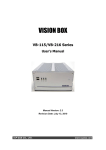
1.4.3 Mirror Image
The mirror image feature is only available in the MAVIS IM-100 camera. When
you enable mirror image mode, the camera will reflect the image’s vertical axis,
before data is transmitted out of the camera.
In factory mode, the mirror image is disabled and the order of transmission for
the pixels in each line is pixel 1, pixel 2, pixel 3, to 640. When mirror image mode
is enabled, the order of transmission for each line is pixel 640, pixel 639, pixel
638, to pixel 1.
Figure 1-3: Mirror Imaging
If you are using the AOI mode (area of interest) in conjunction with
mirror image mode, the apparent location of your AOI may change.
You may need to adjust the location and size of the AOI.
-7-
1.4.4
Gain and Brightness
The Gain and Brightness adjustment functions are accomplished by
manipulation of the sensor’s digital output signal.
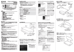
Please refer in Figure 1-4; when the
gain is set to 0, the full 10bit output
range
of
the
camera’s
CMOS
sensor will mapped directly to the
8bit output range of the camera. In
this situation, a gray value of 0 is
output from the camera when the
pixels in the sensor are exposed to
no light and a gray value of 255 is
output when the pixels are exposed
to very bright light. This condition is
defined as 0dB of system gain for
the camera.
As shown in the three graphs
below, increasing the gain setting to
a value greater than 0, maps a
smaller portion of the sensor’s 10bit
range to the camera 8bit output.
When a smaller portion of the
sensor range is mapped to the
camera
output,
the
camera’s
sensitivity to a change in light level
is increased.
This feature can be useful when at
your brightest exposure, a gray
value of less than 255 is achieved.
For example, if a maximum gray
value of 127 is achieved with bright
light, you could increase the gain
setting so that the camera is
operating at 6dB; thus seeing an
increase in gray values to 254.
-8-
Figure 1-4: Gain Settings Mapping
Value
0
28
43
85
128
170
213
255
dB
0dB
2.5dB
3.5dB
6dB
8dB
9.5dB
10.9dB
12dB
Table 1-1 Gain value settings
Please refer to “Figure 1-5”;
Which illustrates the effect of
setting the brightness higher
than the default value of 725. It
should be noted that this setting
moves the response curve to the
left; therefore increasing the 8bit
value output from the camera for
any given 10bit value from the
sensor, and also increasing the
apparent
brightness
of
the
image.
The bottom graph illustrates the
effects of setting the brightness
lower than the default value of
725. It should be noted that this
setting
moves
the
response
curve to the right; therefore
decreasing the 8bit value output
from the camera for any given
10bit value from the sensor and
also decreasing the apparent
brightness of the image.
-9-
Figure 1-5: Brightness Settings Mapping
1.4.5 Lookup Table
MAVIS IM-30/IM-100 cameras have a sensor that reads pixel value at a
10bit depth; however, the camera outputs pixel values at an 8bit depth.
When set for 8bit output, the camera normally uses an internal process to
convert the 10bit pixel values from the sensor to the 8bit values transmitted
out of the camera. When making the 10 to 8bit conversion, the internal
process takes the camera current gain and brightness settings into
account.
The MAVIS IM-30/IM-100 camera allows users to use a custom lookup
table to map the 10bit sensor output to 8bit camera output rather than using
the internal process. When the custom lookup table is enabled, the gain
and brightness settings have no effect. The 10 to 8bit conversion is based
solely on the lookup table.
The lookup table is essentially just a list of 1024 values. Each value in the
table represents the 8bit value that will be transmitted out of the camera
when the sensor reports a particular 10bit value for a pixel. The first number
in the table represents the 8bit value that will be transmitted out of the
camera when the sensor reports that a pixel has a value of 0. The second
number in the table represents the 8bit value that will be transmitted out of
the camera when the sensor reports that a pixel has a value of 1. The third
number in the table represents the 8bit value that will be transmitted out of
the camera when the sensor reports that a pixel has a value of 2. And so
on.
The advantage of the lookup table feature is that it allows the user to
customize the response curve of the camera.
The graphs below represent the contents of two typical lookup tables.
Figure 1-6 is for a lookup
table where the values
are arranged so that the
output
of
the
camera
increases linearly as the
sensor output increases.
Figure 1-6: LUT with Values Mapped in a Linear Fashion
- 10 -
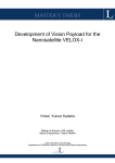
Figure 1-7 is for a lookup table where the values are arranged so that the
camera output increases quickly as the sensor output moves from 0
through 511 and increases gradually as the sensor output moves from 512
through 1023.
Figure 1-7: LUT with Values Mapped for Higher Camera Output at Low Sensor Readings
z
Upload a Lookup Table
The EZView utility offers an LUT enable and upload button that can be
used to easily load a file containing a customized lookup table into the
camera. The file must be plain text and must be formatted correctly.
The file must have 1024 lines with each line
containing two comma-separated values.
The first value on each line represents a 10
bit pixel reading from the sensor and the
second value represents the corresponding
8bit output that will be transmitted from the
camera.
The sample below shows part of a typical
text file for a lookup table. Assuming that you
have enabled the lookup table feature on
your camera and used the upload button to
load a file similar to the sample into the
camera:
The sensor reports that a pixel has a value of
1, the camera will output a value of 0.
The sensor report that a pixel has a value of
6, the camera will output a value of 1.
The sensor report that a pixel has a value of
1019, the camera will output a value of 254.
Figure 1-8 Sample text file
for use LUT upload
- 11 -
1.4.6 Shutter (Exposure)
The camera exposure time is related with shutter speed or camera frame
rate. MAVIS IM-30/IM-100 allowed to set shutter speed range from 20us to
81900us.
While user set the exposure time (shutter speed) longer then frame
acquisition speed then camera frame rate will be reduced.
For example: if user set the frame rate in 30fps but set the shutter speed in
36000us.
Maximum exposure time (Shutter speed) = 1s / frame rate
36000us = 1s / frame rate
Camera real frame rate = 27 frames per second
- 12 -
1.4.7 Input/Output
z
Input Ports
The MAVIS IM-30/IM-100 offers 2 input ports; designated as Input Port 0
and Input Port 1.
Both ports are TTL level. The input ports are accessed
via the 10-pin circular connectors on the back of the camera. Please refer
Table 2-1 for input port pin assignments.
For each port, an input voltage between 0.0 and 1.5VDC indicates a logical
0. An input voltage between 3.5 and 5.0 VDC indicates a logical 1. Typical
current draw for the input port is 1mA.
Figure 1-6 is an example of a typical circuit that you can use to input a
signal into the MAVIS IM-30/IM-100 cameras.
Figure 1-9: Typical Input Circuit
By default, Input Port 0 is assigned to receive an external trigger (Ex-Trig)
signal that can be used to control the start of exposure. Also you can
change the Ex-Trig signal to Input Port 1 and please refer “5.6 External
Trigger” for detail information.
z
Output Ports
The MAVIS IM-30/IM-100 offers 4 output ports; designated as Output Port 0,
Output Port 1, Output Port 2 and Output Port 3, all are TTL level. The
output ports are accessed via the 10-pin circular connectors on the back of
the camera. Please refer Table 2-1 for input port pin assignments.
For each port, an output voltage between 0.0 and 0.44VDC indicates a
logical 0. The maximum low level output voltage (i.e., 0.44VDC) will be
present when the driver is sinking the maximum allowed input current of
- 13 -
24mA. An output voltage between 4.2 and 5.0VDC indicates a logical 1.
The minimum high level output voltage (i.e., 4.2VDC) will be present when
the driver is sourcing the maximum allowed output current of 24mA.
Figure 1-7 is an example of a typical circuit that you can use to monitor an
output port with a LED or an Opto-coupler. Note that current in the circuit is
limited by an external resistor.
Figure 1-10: Typical Output Signal
By default, Output Port 0 is assigned to transmit an integration enabled
(Int-En) signal that indicates when exposure is taking place. By default,
Output Port 1 is assigned to transmit a trigger ready (Trig-Rdy) signal that
goes high to indicate the earliest point at which exposure start for the next
frame can be triggered. Please refer “1.6 Integrate Enabled Signal Timing”
for a detailed camera signal integrate timing chart. The pin assignment of
the camera output signals to physical output ports can be changed. Please
refer “5.7 External Trigger” for detailed information.
- 14 -
1.4.8 External Trigger
The external trigger (Ex-Trig) input signal can be used to control the start of
exposure.
A rising edge or a falling edge can also be used to trigger
exposure start. The External Trigger Mode is also used to enable the
Ex-Trig exposure start control; enabling users to select rising or falling edge
triggering and to assign a physical input port to receive the Ex-Trig signal.
The Ex-Trig signal can be periodic or non-periodic. When the camera is
operating under control of an Ex-Trig signal, the period of the Ex-Trig signal
determines the camera’s frame rate:
1 / Ex-Trig period per second = frame rate
For example, if you are operating a camera with an Ex-Trig signal period of
20ms (0.02s):
1/0.02 = 50 fps
So in this case, the frame rate is 50fps
The minimum high time for a rising edge trigger (or low time for a falling
edge trigger) is 1us.
Exposure Modes
If you are triggering the camera with an Ex-Trig signal, two exposure modes
are available, programmable mode and level controlled mode.
Programmable Exposure Mode
When programmable mode is selected, the length of the exposure is
determined by the shutter setting described in “1.4.6 Shutter (Exposure)”. If
the camera is set for rising edge triggering, exposure starts when the
Ex-Trig signal rises. If the camera is set for falling edge triggering, exposure
starts when the Ex-Trig signal falls.
Figure 1-11: Programmable Exposure with rising edge triggering
- 15 -
Level Controlled Exposure Mode
When level controlled mode is selected, the length of the exposure is
determined by Ex-Trig signal alone. If the camera is set for rising edge
triggering, exposure begins when the Ex-Trig signal rises and continues
until Ex-Trig signal falls. If the camera is set for falling edge triggering,
exposure begins when Ex-Trig signal falls and continues until Ex-Trig signal
rises.
Figure 1-12: Level Controlled Exposure with rising edge triggering
- 16 -
1.4.9 Strobe Control
This feature allows a user to enable and parameterize up to four strobe light
control output signals. The signals are designated as Strobe 0, Strobe 1,
Strobe 2, and Strobe3. Each strobe signal can be set to on or off and active
high or low by logical value, please refer to section 5, “Function Library”, for
command definitions.
The strobe delay is determined by a combination of two values. The first is
the setting in the Delay Value and the range from 0 to 4095. The second is
the Strobe Delay Time Base which has a default value of 1/1024 ms.
Strobe Delay = (Strobe Delay Value Setting) x (Strobe Delay Time Base)
For example: If Delay Value of Strobe 0 is set to 120, then Strobe 0 delay
will be 120/1024ms (or approximately 117us).
The Strobe delay will determine the time between the start of image
exposure and when the strobe signal changes state as show in Figure
1-13.
Figure 1-13: Strobe Signal
As mentioned above, the strobe delay time base is normally fixed at
1/1024ms and the strobe delay is normally adjusted by changing the delay
value setting only. However, if you require a delay that is longer then what
you can achieve by changing the strobe delay value alone, the strobe delay
time base can also be changed. The strobe time base range has a
multiplier of 1 to 85.
For example: with Delay Value of Strobe 1 set to 200 and a Delay Time
Base of 20:
Strobe1 Delay = (Strobe1 Delay Value Setting) x (Strobe Delay Time Base)
Strobe1 Delay = (200) x (20/1024ms)
Strobe1 Delay = 3.9ms
- 17 -
1.5 Spectral Response
Figure 1-11: MAVIS IM30/IM100 Camera Spectral Response
The camera spectral response curve excludes Lens and lighting
source characteristics.
- 18 -
1.6 Integrate Enabled Signal Timing
The time between the start of exposure and the rise of the Integrate Enabled (Int-En)
signal will be less than 10 nanoseconds. The time between the end of exposure and
the fall of Int-En signal will also be less than 10 nanoseconds. This is very good
performance, and is due to the design of the camera output port circuitry.
Figure 1-12: MAVIS IM-30/IM-100 Camera Timing Chart
- 19 -
1.7 Benchmarks
Due the platform and 1394 Host controller bandwidth performance, we have listed
some benchmark information for your reference.
Benchmark test results
Platform Type
Industrial PC Platform
Consumer PC
VISION BOX
Platform Spec.
ROBO-8712E SBC
ASUS
VB-216C
Intel Pentium4
P4S800-MXSE
Intel Core Duo 1.66GHz
2.4GHz
Celeron 2.66GHz
2GB DDR2 533
512MB DDRAM
256MB DDR RAM
32-bit, 33MHz PCI
32-bit, 33MHz PCI
32-bit, 33MHz PCI
Chipset: Intel 945GME
Chipset: Intel 845GV
Chipset: SiS661FX
32-bit OS: Windows XP
32-bit OS: Windows
32-bit OS: Windows
Embedded Service Pack2
XP Service Pack 2
XP Service Pack 2
Max. input
MAVIS IM-100* x
MAVIS IM-100* x
MAVIS IM-100* x 3pcs or
guaranteed:
3pcs or MAVIS
2pcs or MAVIS
MAVIS IM-30** x 8pcs (by
IM-30** x 10pcs
IM-30** x 6pcs
hub function of 1394R3B)
MAVIS acquisition speed data rates:
* When the IM-100 is at full speed image acquisition (100 frames per second) the
data rate will be up to 29.3MB per second.
**When the IM-30 is at full speed image acquisition (30 frames per second) the data
rate will be up to 8.79MB per second.
Some IEEE 1394 interface cards offer three IEEE 1394 connectors but one IEEE
1394 Host controller only. Therefore when you plug more than one IEEE 1394
cameras, the bandwidth will be considered shared usage. Please see below for an
explanation of a “bandwidth sharing” situation, when the number of host controllers is
different.
Number of Host Controllers
IM-100 x 1pcs
IM-100 x 2pcs
IM-100 x 3pcs
IEEE 1394 host controller x 1
100fps/CH
60fps/CH
30fps/CH
IEEE 1394 host controller x 2
100fps/CH
100fps/CH
IM-30 x 1pcs
IM-30 x 2pcs
IM-30 x 3pcs
IEEE 1394 Host controller x 1
30fps/CH
30fps/CH
30fps/CH
IEEE 1394 Host controller x 2
30fps/CH
30fps/CH
30fps/CH
Number of Host Controllers
- 20 -
One CH 100fps,
Two CH 60fps/CH
2 Hardware Reference
2.1 MAVIS IM-30/IM-100
2.1.1 Camera Specification
Item
Image sensor
IM-30
1/2” CMOS Sensor Micron MT9V403, Pixel size: 9.9um x 9.9um
640(H) x 480(V)
Video output pixels
Gain control
Power supply
0 ~ 12dB setting via communication command
+12VDC normal (Supply via 1394 cable)
Max. ~ 1.7W at 12V
Power consumption
Acquisition mode
Connector Interface
IM-100
Free Run (exposure time programmable ), External random trigger
6-Pin IEEE 1394 connector(for video and power)
10-Pin GPIO (General Purpose Input/Output)connector
GPIO connector
Video mode
Protocol
Test image
TTL level with 2 input, 4 output and one +5VDC output
Initial mode: 640 x 480 at 30fps
Initial mode: 640 x 480 at 100fps
Scalable mode: by AOI
Scalable mode: by AOI
IEEE 1394a version. 1.31 (transfer speed 400Mbps)
Gray value internal test pattern generated
Exposure Time
Programmable via IEEE 1394 bus
Brightness
Programmable via IEEE 1394 bus
Temperature
Operating temperature : 0℃ ~ 50℃ (32℉ ~ 122℉)
Storage temperature: -20℃ ~ 60℃ (-4℉ ~ 140℉)
Humidity
Operating humidity : 20% ~ 80%, relative, non-condensing
Storage humidity: 10% ~ 90%, relative, non-condensing
CE/FCC
EMC condition
Dimension
72.5mm (H) x 49mm(W) x 36.7mm(D) without Lens
120g without Lens
Weight
C/CS Mount
Lens Adaptor
- 21 -
2.1.2 Camera Interface
z
IEEE 1394
z
GPIO
Pin
Name
Pin
Name
1
+12VDC
1
Output 0
2
GND
2
Input 0
3
TPB-
3
Output 1
4
TPB+
4
Input 1
5
TPA-
5
Output 2
6
TPA+
6
NC
7
Output 3
8
NC
9
GND
10
NC
Camera rear view
Table 2-1 Camera Interface Connector Pin Assignments
2.1.3 Standard Package Contents
Camera with Lens-cap
Driver CD & Installation Guide
Tripod Adapter with screws
GPIO Wiring Connector
- 22 -
2.2 Optional Accessory
To increase your system’s working performance and reliability, ICP DAS suggests
three optional accessories.
2.2.1 1394 Dual-port Card: IOI-4601-21
The IOI-4601-21 is dual IEEE 1394 host controller PCI
interface card. Capable of supporting simultaneous dual
ports data transmission at rates of 400Mbps.
32-bit PCI local bus complies with PCI 2.1 and 2.2 specification
Host Bus
Use only one IRQ for both OHCI 1.1 channels
Interface Protocol
Bus Master DMA
1394 Bus Transfer Rate
100/200/400 Mbps
Host Bus Burst Data Rate
Up to 133 MB/s burst rate
IEEE-1394 to PCI Chip
2x Ti TSB43AB21
External X 2 (FW-6pin X 2)
1394 Connector
OHCI 1 (FW-6pin X 1)
OHCI 2 (FW-6pin X 1)
1394 Bus Power Connector
Mini 4-pin DC +12V power connector
Bus Power Connector
with mini 4-pin DC + 12V Power Connector
Maximum 1394 Bus Transfer is 800 Mbps (400 Mbps per
Performance
channel)
2.2.2 1394 Latch Cable: CA-1394-45
1394 connector
6-pin male connector with spring latch, PVC molding
UL-20276 cable, 28AWG x 2pairs, 22AWG x 2 conductors.
Cable wiring gauge
Double shielded.
Length
450mm
- 23 -
2.2.3 1394 Repeater: 1394R3B
1394R3B repeater offer 1port to 2 ports IEEE 1394
signal repeat and cable extension need. The
1394R3B allow convert 1394-1995 to 1394a.
Top Side View
Left Side View
Chip
PHY: TI. TSB41AB3
1394 Bus Transfer Rate
100 / 200 / 400 Mbps
Device Interface
A 400-Mbps, 2-port, 3.3V PHY
Power Input Range
DC 12V ~ 30V, Max. 1.35A
Connector
6 Contact Male x3
Right Side Vide
DC - Walkman-type 2.0mm DC Jack x1
Dimension
72mm(W) x 58mm(H) x 20mm(D)
DC power input ONLY for using Notebook 1394 port or 1394
PCMCIA interface card.
- 24 -
3 Installation Guide
MAVIS IM-30/IM100 IEEE 1394 cameras support operation in IPC, PC and Notebook
system platforms. This also installation guide includes information on how to use this
camera correctly and safely. Please read through this installation guide carefully and
follow the installation steps of your specified system platform.
CAUTION
DO NOT open the camera housing in any situation. Touching internal
components may damage camera function. Meanwhile when customer to open
camera housing then warranty will be void immediately.
Be careful not to allow liquids, flammable or metallic material inside of the camera.
3.1 Hardware Installation
3.1.1 IPC/PC Platform
z
Some desktop PCs have a built-in 1394 port with 6-pin 1394 connector;
if your system is one of these, you will be able to use a 1394 cable
connect to your system 1394 port directly.
z
If you choose to use an IPC or your desktop PC without a built-in 1394
port, then please see the following steps to install your 1394 interface
card on a PCI bus:
(1) Remove the computer cover using the instructions from the
computer manual.
(2) Check that there is an empty PCI (32-bit) slot to accommodate the
card.
(3) Remove the blank metal plate located at the back of the selected
slot (if any). Keep the removed screw to fasten the 1394 card after
installation.
(4) Carefully position the 1394 card in the selected PCI slot as
illustrated below. If using a tower computer, orient the board to suit
the board slots.
- 25 -
(5) Once perfectly aligned with an empty slot, press the card firmly but
carefully in to the connector.
(6) Anchor the board by replacing the screw.
(7) Using 1394 cable to connect MAVIS IM-30/IM-100 1394 camera to
1394 card and GPIO cable wiring if necessary. For image
acquisition test please refer to the “EZView Utility”.
(8) Turn on the system and you will be able to find the 1394 Host
controller device with Device Manager.
(9) If you need to extend your
working
distance,
please
using 1394 repeater directly.
DO NOT input DC power to 1394 repeater when using
IPC/PC platform. The DC power input may damage your
1394 card or 1394 host controller circuit.
- 26 -
3.1.2 Notebook PC / PCMCIA Socket
z
If
your
notebook
PC
has
an
iLink/S400 interface port then your
notebook PC has a built-in 1394 host
controller. So please follow the steps
for installation.
(1) Please prepare one IEEE 1394
repeater, one 4-pin to 6-pin IEEE 1394 cable, one 6-pin to 6-pin
IEEE 1394 cable and one walkman type DC power adapter first.
(2) Please use 4-pin to 6-pin IEEE 1394 cable and 4-pin connector to
iLink/S400 interface port and 6-pin connector to 1394 repeater.
(3) When 6-pin connection to 1394 repeater, then please plug in DC
power adaptor and another 6-pin to 6-pin 1394 cable.
(4) 6-pin
to
connected
6-pin
to
IM-30/IM-100
1394
MAVIS
IEEE
1394 port and GPIO
wiring
connection
necessary.
- 27 -
if
z
If your notebook PC does not have a
1394 interface port, then please plug
your 1394 Card Bus to PCMCIA socket,
and follow the steps for installation.
(1) Please prepare one IEEE 1394 PCMCIA card, IEEE 1394 repeater,
two 6-pin to 6-pin IEEE 1394 cable and one walkman type DC
power adapter first.
(2) Plug IEEE 1394 PCMCIA card to Notebook PCMCIA socket as
below.
(3) Plug 6-pin connector to IEEE 1394 PCMCIA card and another 6-pin
connected to IEEE 1394 repeater.
(4) When 6-pin connection to 1394 repeater is established, please plug
in DC power adaptor and another 6-pin to 6-pin 1394 cable.
(5) 6-pin
to
connected
6-pin
to
IM-30/IM-100
1394
MAVIS
IEEE
1394 port and GPIO
wiring
connection
necessary.
- 28 -
if
3.2 Driver Installation
Do not plug in any MAVIS IM-30/IM-100 cameras before driver installation has
been completed. Please refer to the following installation steps for various
programming environment specific installations.
3.2.1 For Visual Studio (VC/VB/BCB/VC#.NET) Users
1.
Insert the MAVIS Support CD to CD-ROM/DVD-ROM drive.
2.
The MAVIS Support CD will start to prepare driver installation as below.
3.
Please click “Next” button for driver installation.
- 29 -
4.
5.
Please enter user name and company name, then click “Next” button.
The MAVIS series default path located at C:\MAVIS\, and you can click
“Change..” button to change driver installation path, otherwise please click
“Next” button for continue driver installation.
- 30 -
6.
Please click the “Install” button
7.
Driver installing
- 31 -
8.
When driver install is completed, please click the “Finish” button and restart
your system.
9.
After system re-boot, please plug in the MAVIS IM-30/IM-100 cameras and
go to “Device Manager” and make sure you see the “Generic IEEE-1394
digital camera” in the list of “ICP DAS MAVIS”.
10.
If your system had install other vendor’s 1394 camera driver, then you may
need to remove it and change to install MAVIS driver by manually.
11.
When the installation has been completed, open “EZView” utility for image
acquisition testing, please refer to “4. EZView Utility” for details.
- 32 -
3.2.2 For LabVIEW Users
If you prefer to use LabVIEW from NI (National Instruments) for your system
development, then we’ll suggest you to use NI-IMAQ directly.
The MAVIS IM-30/IM-100 series are fully compatible with NI-IMAQ-1394.
Please just select “NI-IMAQ IEEE 1394 IIDC Digital Camera” driver for your
installation and DO NOT install the MAVIS driver.
After installation is completed, then you can use “Measurement & Automation
Explorer” of NI for configuration of the camera and the image grab test.
When you install the NI-IMAQ-1394 driver, all MAVIS official drivers,
API and EZView utilities will fail to work.
- 33 -
4 EZView Utility
Once hardware installation is complete, ensure that cameras are configured correctly
in Device Manager before running the EZView utility. This chapter outlines how to
establish a vision system and how to manually control the MAVIS IM-30/IM-100
camera series to verify correct operation. EZView provides a simple yet powerful
means to setup, configure, test, and debug the vision system.
Note: EZView is only available for Windows 2000/XP with a recommended screen
resolution higher than 1024 x 768.
4.1 Overview
Figure 4-1: EZView Utility Main Screen
- 34 -
4.2 Component Description
File
The File menu offers the “Enable Test Image”, “Lookup Table”, Strobe Control”,
“Strobe Time Base”, “External Trigger” functions and “About EZView” for version
control information as below.
Test Image Mode
- 35 -
Lookup Table
The EzView utility has offer interface window for user to ‘Download’ the LUT
information of MAVIS. Meanwhile, user can enable the ‘Enable LUT’ function for
‘Upload’ custom LUT information to MAVIS operation.
Strobe Control
The EzView utility offer interface window for Strobe Control parameter setting
and those parameters only effective when configure the specific output port for
strobe operation.
- 36 -
Strobe Time Base
This is for change strobe control Duration Time Base. The Duration Time Base
range from 1 ~ 85 and the time base denominator is 1/1024ms. For example,
when Strobe Duration value is 600 and set the Duration Time Base to 50, then
the strobe light up duration time will be: 600 x (50/1024ms) = 24.4ms.
External Trigger
“External Trigger” function
menu.
“External Trigger” function
has
offer
control
two
setting,
exposure
include:
“Programming Mode” and
“Level Mode”.
- 37 -
“External Trigger” has offer
two hardware trigger control
by “Input 0” and “Input 1”
and
“Software”
trigger
control.
All
“External
function
Trigger”
parameters
effective
when
only
“External
Trigger” function is setting
to “Active”.
About EZView
- 38 -
Tree Browser
The Tree Browser window lists the 1394 Host controller ports and how many
MAVIS 1394 cameras are available at the local computer.
Display Window
The display window displays full and specifically requested AOI size images and
image effects.
- 39 -
Tool Icons
Camera Scan
Click the Camera Scan icon to list the MAVIS 1394 cameras available
at the local computer.
Measure FPS
Click the Measure FPS icon and a pop-up will show the result of the
frames per second test
Snap Shot
Click the SnapShot icon. A single image will appear in the Display
Window
Video Capture
Click the Video Capture icon. A video frame will appear in the Display
window
AOI
Clicking the ROI icon will allow using the mouse to select the area of
interest within the image.
Full Screen
Clicking the Full Screen icon will disable the AOI function and re-size
the display to the default, full resolution: 640 x 480.
IO Setting
Click the IO Setting icon to bring up the GPIO dialog box. Select the
port to access and select the digital input / output setting.
IO Setting Screen
Save Snap Shot
Click Save Snap Shot icon to save current single image to a BMP file.
- 40 -
Control bar
Select the Frame Rate
The
EZView
acquisition
utility
speed
offers
for
30fps
default
demonstration. Selection of the Frame
Rate control bar is only available while
using the MAVIS IM-100.
Brightness
Click and hold the left mouse button on
the Brightness slider and drag the cursor
to change its value. Values range from
0-1023.
Shutter
Click and hold the left mouse button on
the Shutter slider and drag the cursor to
change its value. The shutter speed
range from 20us to 81900us. ( 0.02ms ~
81.9ms)
Gain
Click and hold the left mouse button on
the Gain slider and drag the cursor to
change its value. Values range from 0 to
255.
- 41 -
5 EzVIEW_Fly Utility
The EzVIEW_Fly is a friendly utility designed for ICPDAS machine automation
customer. The EzVIEW_Fly utility now supported PISO-PS400 (driver version 3.0),
ET-M8194H (driver version 1.0) and FRNET I/O. User can very easily to setup,
configure, test, and debug about MAVIS cameras image acquisition by external
hardware trigger in EzVIEW_Fly utility.
This chapter outlines how to establish a vision with motion control system and how to
setting the correct functions and parameters for I/O trigger, trigger compare or random
trigger to verify correct operation.
Note: EzVIEW_Fly is only available for Windows 2000/XP with a recommended
screen resolution higher than 1024 x 768.
5.1 Overview
Figure 5-1: EzVIEW_Fly Utility Main Screen
- 42 -
5.2 Configuration
The Configuration included Feature Setting, Advanced Feature and I/O Setting.
Feature Setting
The Main Feature Setting window included features setting for MAVIS Camera
and Motion Module products. Please refer 5.2.1 and 5.2.2 for detail information.
Advanced Features
The Advanced Feature included Test Image and Lookup Table functions of
MAVIS and please refer Chapter 4 EZView utility for the operation description.
I/O Setting
The I/O Setting function offer the interface window same with EZView utility and
please just refer Chapter 4 EZView utility for the operation description.
- 43 -
5.2.1 Feature Setting of MAVIS Camera
The MAVIS Camera included MAVIS Main Feature, ROI Setting and Trigger
Setting function and user can refer the operation as Chapter 4 EZView utility.
Meanwhile user must to click ‘Apply’ button for save your setting into the MAVIS.
In this page the ‘Enable External Trigger’ function of Trigger Setting, it is only for
MAVIS trigger input (by TTL signal voltage) port used and no matter with any
motion trigger pulse.
- 44 -
5.2.2 Feature Setting of Motion Module
The Motion Module now supported ET-M8194H and PISO-PS400, and each time
user only can choose one product model for motion control feature setting and
single axis operation.
EzVIEW_Fly utility required ET-M8194H or PISO-PS400 for hardware
trigger pulse operation. For hardware installation, please follow the
description of ET_8194H_QuickStart or PISO-PS400_Getting_Started
for operation correctly.
Main Feature Setting of Motion Module
Regarding the parameters meaning, please refer the ET_8194H_QuickStart or
PISO-PS400_Getting_Started for detail information.
Area
Functionality
Parameters
A
Motion Controller Selection
ET-M8194H、PISO-PS400
B
Output Pulse Mode
CCW、PULSE DIR
- 45 -
C
Acceleration Mode
T-Curve、S-Curve、Constant
D
Limitation +/- Logic
High、Low
E
Parameters
Start Velocity、Acceleration Velocity、Driving
Velocity、Output Pulse
F
Operation Command
Servo On/Off、Home*、Forward、Reverse、
Reset、Stop
G
Logical Position、Encoder Position、Driving
Read Status
Speed
Home* - user must install limitation sensor for home operation.
¾
When choose ET-M8194H
When choose ET-M8194H then please input your ET-M8194H IP address
and click ‘Connection’ button for Ethernet connection.
User can use EzMove utility of ET-M8194H for IP address configuration or
detail function operation. (Please refer the user manual of ET-M8194H).
- 46 -
¾
When choose PISO-PS400
Please click ‘Initial’ button for PISO-PS400 card initialization. This is only
work in PISO-PS400 driver 3.0 and operation for AXIS_X only.
5.3 Help – About EzVIEW_Fly
5.4 Tool Icons
Camera Scan
Click the Camera Scan icon to list the MAVIS 1394 cameras available
at the local computer.
Snap Shot
Click the SnapShot icon. A single image will appear in the Display
Window
Video Capture
Click the Video Capture icon. A video frame will appear in the Display
window
Trigger Setting
Click the Trigger Setting icon to bring up the MAVIS and Motion trigger
function setting screen as 5.4.1 description.
Trigger Capture
Clicking the Trigger Capture icon. The image will appear in the Display
while MAIVS received the external trigger.
Trigger Stop
Clicking the Trigger Stop icon will disable the Trigger Capture
function.
- 47 -
5.4.1 Trigger Setting
MAVIS
External Trigger Setting
The check box must enable for
trigger capture.
Selected the Trigger Mode and
user can refer 1.4.8 for external
trigger mode detail information.
Selected the Trigger Input port
and ensure the wiring correctly.
Strobe Setting
Selected output port and ensure
the wiring correctly.
Selected ‘On’ for enable the strobe
control function.
- 48 -
Selected the active polarity mode
and user can refer 1.4.9 for Strobe
Control polarity definition.
Setting
the
necessary
delay
and
value
please
in
refer
1.4.9.for the formula of delay time.
Setting the strobe duration and
time base and please refer 1.4.9
for the formula of duration time.
Motion
Virtual Trigger
Enable the check box while used
FRNET for I/O trigger simulation.
Selected the output port of FRNET
and ensure the wiring correctly.
Setting the trigger pulse frequency
of FRNET.
Physical Trigger
Note – Please refer the Hardware Installation of PISO-PS400 or ET-M8194H for the
wiring of motion in position signal output to MAVIS trigger input port.
Enable the check box while used
PISO-PS400 or ET-M8194H for
received the in position signal from
encoder / sensor.
Enable the check box of Trigger
Compare and setting the Total
Pulse
and
Trigger
Pitch
for
equidistance trigger.
Enable the check box while active
the trigger pulse in randomized.
- 49 -
6 Function Library
This chapter describes the API for MAVIS IM-30/IM-100 cameras. Users can use
these functions to develop application programs under Visual C++ 6.0, Visual Basic
6.0 , Boland C++ Builder 6.0, and C#.NET 2003.
The MAVIS DLL file (IMCamera.dll) is common to use in Visual C++, Visual Basic,
Boland C++ Builder and C#.NET development language.
For Visual C++ and Boland C++ Builder, please just follow standard Syntax
description to use.
For Visual Basic, we have offer “IMCamera.bas” module file in our sample program
and user also can define or modify function module file as you need.
For C#.NET, we have defined a class “Mavis” in our sample program and we are
strong to recommend that user can build own class as you need.
For example:
public class Mavis
{
[DllImport("IMCAMERA.DLL")]
public static extern short IMC_Camera_Scan(out IMC_DEVICE_DATA
pCamera_List);
[DllImport("IMCAMERA.DLL")]
public static extern short IMC_Camera_Init( int camera_idx, ref IntPtr pHandle );
[DllImport("IMCAMERA.DLL")]
public static extern short IMC_FrameRate_Set( IntPtr Camera_Handle, ulong
FrameRate, bool bMirror );
[DllImport("IMCAMERA.DLL")]
public static extern short IMC_Camera_Close( IntPtr Camera_Handle );
…
}
Please refer to Table 6-1 List of Functions for functions by category. All the data types
follow Microsoft standard definitions.
- 50 -
6.1 List of Functions
Category
Section
Function
IMC_Camera_Scan
Camera Management
5.2
IMC_Camera_Init
IMC_Camera_Close
IMC_ImageAcquisition_Start
IMC_Image_Acquire
IMC_ImageAcquisition_Stop
Camera Acquisition
5.3
IMC_AcquisitionFrame_Copy
IMC_AcquisitionFrame_Save
IMC_Live_Acquire
IMC_LiveAcquisition_Stop
IMC_FrameRate_Set
IMC_Shutter_Get
IMC_Shutter_Set
Camera Configuration
5.4
IMC_Gain_Get
IMC_Gain_Set
IMC_Brightness_Get
IMC_Brightness_Set
IMC_OutputPort_Status
IMC_OutputPort_Configure
Digital Input/Output
5.5
IMC_OutputPort_Write
IMC_InputPort_Read
IMC_InputPort_ReadAll
IMC_Trigger_Enable
External Trigger
5.6
IMC_Trigger_Disable
IMC_Trigger_ReadConfiguration
IMC_StrobeControl_SetConfiguration
Strobe Control
5.7
IMC_StrobeControl_ReadConfiguration
IMC_StrobeTimeBase_SetDurationTime
IMC_StrobeTimeBase_ReadConfiguration
IMC_LUT_Read
Look Up Table
5.8
IMC_LUT_SetStatus
IMC_LUT_ReadStatus
IMC_LUT_Write
AOI (Area of Interest)
5.9
IMC_AOI_Configure
Advanced Features
5.10
IMC_TestImage_Enable
IMC_TestImage_Disable
Table 5-1: List of Functions
- 51 -
6.2 Programming Flowchart
z
Camera scan & initial
IMC_Camera_Scan
z
IMC_Camera_Init
Camera close
IMC_Camera_Close
z
Camera parameters setting
IMC_Camera_Scan
IMC_Camera_Init
IMC_FrameRate_Set
IMC_Shutter_Set
IMC_Gain_Set
IMC_Brightness_Set
z
Check camera setting
IMC_Camera_Scan
IMC_Camera_Init
IMC_Shutter_Get
IMC_Gain_Get
IMC_Brightness_Get
z
Snapshot
IMC_Camera_Scan
IMC_Camera_Init
IMC_ImageAcquisition_Start
- 52 -
IMC_Image_Acquire
IMC_ImageAcquisition_Stop
z
Live continue images capture
IMC_Camera_Scan
IMC_Camera_Init
IMC_ImageAcquisition_Start
z
IMC_Live_Acquire
Save single image to BMP file
IMC_Camera_Scan
IMC_Camera_Init
IMC_AcquisitionFrame_Save
z
IMC_LiveAcquisition_Stop
IMC_ImageAcquisition_Stop
Copy image to memory buffer
IMC_Camera_Scan
IMC_Camera_Init
IMC_ImageAcquisition_Start
IMC_Live_Acquire
IMC_LiveAcquisition_Stop
IMC_AcquisitionFrame_Copy
z
External trigger for image acquisition
IMC_Camera_Scan
IMC_Camera_Init
IMC_Trigger_Enable
IMC_ImageAcquisition_Start
IMC_Live_Acquire
IMC_Trigger_Disable
IMC_LiveAcquisition_Stop
z
Camera digital output setting
IMC_Camera_Scan
IMC_Camera_Init
IMC_OutputPort_Configure
IMC_OutputPort_Write
IMC_OutputPort_Status
- 53 -
z
Strobe control
IMC_Camera_Scan
IMC_Camera_Init
IMC_StrobeControl_SetConfiguration
IMC_StrobeControl_ReadConfiguration
IMC_StrobeTimeBase_SetDurationTime
IMC_StrobeTimeBase_ReadConfiguration
z
Check camera digital input
IMC_Camera_Scan
IMC_Camera_Init
IMC_InputPort_Read
IMC_InputPort_ReadAll
z
Camera AOI setting
IMC_Camera_Scan
IMC_Camera_Init
IMC_AOI_Configure
z
Camera test image
IMC_Camera_Scan
IMC_Camera_Init
IMC_TestImage_Enable
IMC_ImageAcquisition_Start
IMC_Live_Acquire
IMC_TestImage_Disable
IMC_LiveAcquisition_Stop
- 54 -
z
Read camera Lookup Table
IMC_Camera_Scan
IMC_Camera_Init
IMC_LUT_Read
z
Modify camera Lookup Table
IMC_Camera_Scan
IMC_Camera_Init
IMC_LUT_SetStatus
- 55 -
IMC_LUT_Write
6.3 Camera Management
IMC_Camera_Scan
Syntax:
Visual C++ 6.0 / Boland C++ Builder 6.0:
short IMC_Camera_Scan ( PIMC_DEVICE_DATA pCamara_List);
Visual Basic 6.0
IMC_Camera_Scan (pCamera_List As IMC_DEVICE_DATA) As Integer
C#.NET 2003
Mavis.IMC_Camera_Scan(out IMC_DEVICE_DATA pCamera_List);
Description:
This function scans all available MAVIS cameras in system. After this function
returns, this structure contains all available MAVIS cameras in system.
Parameters:
pCamera_List
The pointer to the IMC_DEVICE_DATA structure.
Return:
ERROR_SUCCESSFUL
Successfully
ERROR_NO_CAMERA
No MAVIS camera available in system
- 56 -
IMC_Camera_Init
Syntax:
Visual C++ 6.0 / Boland C++ Builder 6.0:
short IMC_Camera_Init ( int camera_idx, HANDLE* pHandle);
Visual Basic 6.0
IMC_Camera_Init (ByVal camera_idx As Long, ByRef pHandle As Long) As Integer
C#.NET 2003
Mavis.IMC_Camera_Init( int camera_idx, ref IntPtr pHandle );
Description:
This function initializes the MAVIS cameras and returns a handle for the other
functions. The function is required to enable and start one MAVIS camera. The
initialized state will be maintained until calling IMC_Camera_Close().
Parameters:
camera_idx
The index based on the IMC_DEVICE_DATA structure returned by
IMC_Camera_Scan()
pHandl :
The pointer to the MAVIS camera. This handle will be needed by other
functions.
Return:
ERROR_SUCCESSFUL
Successfully
ERROR_INVALID_IDX
The index is not in valid range (1 to scanned
cameras).
ERROR_DEVICE_OCUPPIED
The camera is used by other application.
ERROR_NO_CAMERA
No MAVIS camera response to the initialization
command.
ERROR_DEVICE_INIT
Fail to initialize the camera
ERROR_VIDEOFORMAT_SET
Fail to set the DEFAULT_VIDEO_FORMAT
ERROR_VIDEOMODE_SET
Fail to set the DEFAULT_VIDEO_MODE
ERROR_FRAMERATE_SET
Fail to set the DEFAULT_VIDEO_FRAME_RATE
ERROR_CAMERA_CREATE
Fail to create the camera structure.
- 57 -
IMC_Camera_Close
Syntax:
Visual C++ 6.0 / Boland C++ Builder 6.0:
short IMC_Camera_Close ( HANDLE Camera_Handle);
Visual Basic 6.0
IMC_Camera_Close (ByVal Camera_Handle As Long) As Integer
C#.NET 2003
Mavis.IMC_Camera_Close( IntPtr Camera_Handle );
Description:
This function releases the allocated resources and closes the MAVIS camera. Once
the camera is released by IMC_Camera_Close(), the other functions cannot access
that camera.
Parameters:
Camera_Handle
The handle for MAVIS camera, use the handle gotten from the
‘pHandle’ parameter of IMC_Camera_Init().
Return:
ERROR_SUCCESSFUL
Successfully
ERROR_DEVICE_UNINIT
The specific camera has not been initialized
ERROR_INVALID_CAMERA
The handle is invalid
ERROR_1394FUNC_INCORRECT The error caused by port incorrect operation
ERROR_CAMERA_CREATE
Fail to create the camera structure
- 58 -
6.4 Camera Acquisition
IMC_ImageAcquisition_Start
Syntax:
Visual C++ 6.0 / Boland C++ Builder 6.0:
short IMC_ImageAcquisition_Start ( HANDLE Camera_Handle);
Visual Basic 6.0
IMC_ImageAcquisition_Start (ByVal Camera_Handle As Long) As Integer
C#.NET 2003
Mavis.IMC_ImageAcquisition_Start( IntPtr Camera_Handle );
Description:
This function starts the Image Acquisition. The camera needs be initialized with
IMC_Camera_Init().
Parameters:
Camera_Handle
The handle for MAVIS camera, use the handle gotten from the
‘pHandle’ parameter of IMC_Camera_Init().
Return:
ERROR_SUCCESSFUL
Successfully
ERROR_CAMERA_CREATE
The Camera_Handle is NULL.
ERROR_DEVICE_UNINIT
The specific camera has not been initialized.
ERROR_INVALID_CAMERA
The handle is invalid.
ERROR_1394FUNC_INCORRECT
The error caused by port incorrect operation.
ERROR_ACQUIMAGE_START
Fail to start the image acquisition.
- 59 -
IMC_ImageAcquire
Syntax:
Visual C++ 6.0 / Boland C++ Builder 6.0:
short IMC_ImageAcquire ( HANDLE Camera_Handle, PVOID* ppData );
Visual Basic 6.0
IMC_ImageAcquire (ByVal Camera_Handle As Long, ppData As Long) As Integer
C#.NET 2003
Mavis.IMC_Image_Acquire( IntPtr Camera_Handle, ref IntPtr ppData );
Description:
This function sends the request to camera and receives the frame package when the
acquisition completes. The IMC_ImageAcquisition_Start () should be called before
calling this function.
Parameters:
Camera_Handle
The handle for MAVIS camera, use the handle gotten from the
‘pHandle’ parameter of IMC_Camera_Init().
ppData
The pointer to the Address that contains the acquisition data.
Return:
ERROR_SUCCESSFUL
Successfully
ERROR_CAMERA_CREATE
The Camera_Handle is NULL.
ERROR_DEVICE_UNINIT
The specific camera has not been initialized.
ERROR_INVALID_CAMERA
The handle is invalid.
ERROR_1394FUNC_INCORRECT
The error caused by port incorrect operation.
ERROR_IMAGE_ACQUIRE
Failure in frame acquisition
- 60 -
IMC_ImageAcquisition_Stop
Syntax:
Visual C++ 6.0 / Boland C++ Builder 6.0:
short IMC_ImageAcquisition_Stop ( HANDLE Camera_Handle);
Visual Basic 6.0
IMC_ImageAcquisition_Stop (ByVal Camera_Handle As Long) As Integer
C#.NET 2003
Mavis.IMC_ImageAcquisition_Stop( IntPtr Camera_Handle );
Description:
This
function
stops
the
Image
Acquisition
that
started
with
IMC_ImageAcquisition_Start() . Be aware that the buffer that contains the acquisition
data will be destroyed after calling this function.
Parameters:
Camera_Handle
The handle for MAVIS camera, use the handle gotten from the
‘pHandle’ parameter of IMC_Camera_Init().
Return:
ERROR_SUCCESSFUL
Successfully
ERROR_CAMERA_CREATE
The Camera_Handle is NULL.
ERROR_DEVICE_UNINIT
The specific camera has not been initialized.
ERROR_INVALID_CAMERA
The handle is invalid.
ERROR_1394FUNC_INCORRECT
The error caused by port incorrect operation.
ERROR_ACQUIMAGE_STOP
Fail to stop the image acquisition.
- 61 -
IMC_AcquisitionFrame_Copy
Syntax:
Visual C++ 6.0 / Boland C++ Builder 6.0:
short IMC_AcquisitionFrame_Copy ( HANDLE Camera_Handle, PVOID pData );
Visual Basic 6.0
IMC_AcquisitionFrame_Copy (ByVal Camera_Handle As Long, ByRef pData As Any) As
Integer
C#.NET 2003
Mavis.IMC_AcquisitionFrame_Copy( IntPtr Camera_Handle, IntPtr
pData);
Description:
This function copies the acquisition frame into the buffer. IMC_Image_Acquire ()
should be called before calling this function. This function is helpful to store the
acquisition frame.
Parameters:
Camera_Handle
The handle for MAVIS camera, use the handle gotten from the
‘pHandle’ parameter of IMC_Camera_Init().
pData
The pointer to the buffer that acquisition frame will be copied
into.
Return:
ERROR_SUCCESSFUL
Successfully
ERROR_CAMERA_CREATE
The Camera_Handle is NULL.
ERROR_DEVICE_UNINIT
The specific camera has not been initialized.
ERROR_INVALID_CAMERA
The handle is invalid.
ERROR_NOFRAME_AVAILABLE
No Acquisition frame is available.
- 62 -
IMC_AcquisitionFrame_Save
Syntax:
Visual C++ 6.0 / Boland C++ Builder 6.0:
short
IMC_AcquisitionFrame_Save
(
HANDLE
Camera_Handle,
LPCTSTR
strFileName );
Visual Basic 6.0
IMC_AcquisitionFrame_Save (ByVal Camera_Handle As Long, ByVal strFileName As
String) As Integer
C#.NET 2003
Mavis.IMC_AcquisitionFrame_Save(
strFileName);
IntPtr
Camera_Handle,
string
Description:
This function starts the Image Acquisition, and then saves the acquired image to a
file. Currently, only BMP format is support. The camera needs be initialized with
IMC_Camera_Init().
Parameters:
Camera_Handle
The handle for MAVIS camera, use the handle gotten from the
‘pHandle’ parameter of IMC_Camera_Init().
strFileName
The string saves the full path-name of target image.
Return:
ERROR_SUCCESSFUL
Successfully
ERROR_INVALID_FILENAME
The strFileName is NULL.
ERROR_CAMERA_CREATE
The Camera_Handle is NULL.
ERROR_DEVICE_UNINIT
The specific camera has not been initialized.
ERROR_INVALID_CAMERA
The handle is invalid.
ERROR_1394FUNC_INCORRECT
The error caused by port incorrect operation.
ERROR_ACQUIMAGE_START
Fail to start the image acquisition.
ERROR_IMAGE_ACQUIRE
Failure in frame acquisition
ERROR_ACQUIMAGE_STOP
Fail to stop the image acquisition.
ERROR_BITMAPFILE_CREATE
Fail to create the bitmap file.
ERROR_BITMAPFILE_WRITE
Fail to write the data into bitmap file.
- 63 -
IMC_Live_Acquire
Syntax:
Visual C++ 6.0 / Boland C++ Builder 6.0:
short
IMC_Live_Acquire
(
HANDLE
Camera_Handle,
void
(__stdcall
*callbackAddr)(void* pFrame) );
Visual Basic 6.0
IMC_Live_Acquire (ByVal Camera_Handle As Long, ByVal callbackAddr As Long) As
Integer
C#.NET 2003
Mavis.IMC_Live_Acquire( IntPtr Camera_Handle, Callback cbf );
Description:
This function starts one thread to call IMC_ImageAcquire() continuously. If the
callbackAddr is valid, the function will be called after each IMC_ImageAcquire().
This function helps to simplify the programming for continuous Image-Acquisition.
The IMC_ImageAcquisition_Start () should be called before calling this function.
It is strongly recommended to stop the continuous Image Acquisition with
IMC_LiveAcquisition_Stop() function. Specially, in Visual Basic exiting the VB
program without calling IMC_LiveAcquisition_Stop() will terminate Visual Basic.
Parameters:
Camera_Handle
The handle for MAVIS camera, use the handle gotten from the
‘pHandle’ parameter of IMC_Camera_Init().
callbackAddr
The Address of CallBack Function..
In Visual C++, the CallBack function must be declared as
__stdcall FunctionName (void* pFrame).
In Visual Basic, one separate module contains the Callback
Function.
- 64 -
Return:
ERROR_SUCCESSFUL
Successfully
ERROR_CAMERA_CREATE
The Camera_Handle is NULL.
ERROR_DEVICE_UNINIT
The specific camera has not been initialized.
ERROR_INVALID_CAMERA
The handle is invalid.
ERROR_ACQUISITION_BUSY
The camera is acquiring image
ERROR_EVENT_CREATE
Fail to create the associated event
ERROR_THREAD_CREATE
Fail to create the thread
- 65 -
IMC_LiveAcquisition_Stop
Syntax:
Visual C++ 6.0 / Boland C++ Builder 6.0:
short IMC_LiveAcquisition_Stop ( HANDLE Camera_Handle);
Visual Basic 6.0
IMC_LiveAcquisition_Stop (ByVal Camera_Handle As Long) As Integer
C#.NET 2003
Mavis.IMC_LiveAcquisition_Stop( IntPtr Camera_Handle );
Description:
This function ends the thread created by IMC_Live_Acquire() and then stops the
Image Acquisition.
Parameters:
Camera_Handle
The handle for the MAVIS camera, use the handle gotten from the
‘pHandle’ parameter of IMC_Camera_Init().
Return:
ERROR_SUCCESSFUL
Successfully
ERROR_CAMERA_CREATE
The Camera_Handle is NULL.
ERROR_DEVICE_UNINIT
The specific camera has not been initialized.
ERROR_INVALID_CAMERA
The handle is invalid.
ERROR_ACQUIMAGE_STOP
Fail to stop the image acquisition.
- 66 -
6.5 Camera Configuration
IMC_FrameRate_Set
Syntax:
Visual C++ 6.0 / Boland C++ Builder 6.0:
short IMC_FrameRate_Set ( HANDLE Camera_Handle, ULONG FrameRate, BOOL
bMirror = FALSE);
Visual Basic 6.0
IMC_FrameRate_Set (ByVal Camera_Handle As Long, ByVal FrameRate As Long,
Optional ByVal bMirror As Boolean) As Integer
C#.NET 2003
Mavis.IMC_FrameRate_Set(
IntPtr
Camera_Handle,
ulong
FrameRate,
bool
bMirror );
Description:
This function sets the Frame Rate for MAVIS cameras. The camera needs to be
initialized with IMC_Camera_Init().
Parameters:
Camera_Handle
The handle for MAVIS camera, use the handle gotten from the
‘pHandle’ parameter of IMC_Camera_Init().
FrameRate
The Frame Rate setting for the MAVIS camera. The valid values
are FRAME_RATE_30, FRAME_RATE_60, FRAME_RATE_100
bMirror
Enable/disable the Mirror mode. This flag is active for
FRAME_RATE_100 Frame Rate.
- 67 -
Return:
ERROR_SUCCESSFUL
Successfully
ERROR_INVALID_FRAMERATE
The invalid FrameRate
ERROR_CAMERA_CREATE
The Camera_Handle is NULL.
ERROR_DEVICE_UNINIT
The specific camera has not been initialized.
ERROR_INVALID_CAMERA
The handle is invalid.
ERROR_1394FUNC_INCORRECT
The error caused by port incorrect operation.
ERROR_VIDEOFORMAT_SET
Fail to set the Video Format
ERROR_VIDEOMODE_SET
Fail to set the Video Mode
ERROR_FRAMERATE_SET
Fail to set the Frame Rate
The below errors only for FRAME_RATE_100:
ERROR_SIZE_INQUIRE
Fail to inquire the maximum size
ERROR_SIZE_STATUS
Fail to get the current size-settings
ERROR_SIZE_AOISET
Fail to set the size
ERROR_POSITION_AOISET
Fail to set the Left-Top position
ERROR_CORLOR_AOISET
Fail to set the color mode
ERROR_BYTEPERPACKAGE_AOI_SET
Fail to set the bytes per package
- 68 -
IMC_Shutter_Get
Syntax:
Visual C++ 6.0 / Boland C++ Builder 6.0:
short IMC_Shutter_Get ( HANDLE Camera_Handle, int* pShutterValue);
Visual Basic 6.0
IMC_Shutter_Get (ByVal Camera_Handle As Long, ByRef
pShutterValue As Long) As
Integer
C#.NET 2003
Mavis.IMC_Shutter_Get( IntPtr Camera_Handle, IntPtr pShutterValue );
Description:
This function gets the current setting of Shutter Time. The camera needs be
initialized with IMC_Camera_Init().
Parameters:
Camera_Handle
The handle for MAVIS camera, use the handle gotten from the
‘pHandle’ parameter of IMC_Camera_Init().
pShutterValue
The pointer to integer that contains the Shutter-Time value
(Timing unit in microsecond)
Return:
ERROR_SUCCESSFUL
Successfully
ERROR_CAMERA_CREATE
The Camera_Handle is NULL.
ERROR_DEVICE_UNINIT
The specific camera has not been initialized.
ERROR_INVALID_CAMERA
The handle is invalid.
- 69 -
IMC_Shutter_Set
Syntax:
Visual C++ 6.0 / Boland C++ Builder 6.0:
short IMC_Shutter_Set ( HANDLE Camera_Handle, int ShutterValue);
Visual Basic 6.0
IMC_Shutter_Set (ByVal Camera_Handle As Long, ByVal ShutterValue As Long) As
Integer
C#.NET 2003
Mavis.IMC_Shutter_Set( IntPtr Camera_Handle, int ShutterValue );
Description:
This function updates the setting of Shutter Time. The camera needs be initialized
with IMC_Camera_Init().
Parameters:
Camera_Handle
The handle for MAVIS camera, use the handle gotten from the
‘pHandle’ parameter of IMC_Camera_Init().
ShutterValue
The Shutter-Time value with valid range from 20 to 81900. (Timing
unit in microsecond)
Return:
ERROR_SUCCESSFUL
Successfully
ERROR_CAMERA_CREATE
The Camera_Handle is NULL.
ERROR_DEVICE_UNINIT
The specific camera has not been initialized.
ERROR_INVALID_CAMERA
The handle is invalid.
ERROR_INAVLID_VALUE
The invalid Shutter-Time value
- 70 -
IMC_Gain_Get
Syntax:
Visual C++ 6.0 / Boland C++ Builder 6.0:
short IMC_Gain_Get ( HANDLE Camera_Handle, int* pGainValue);
Visual Basic 6.0
IMC_Gain_Get (ByVal Camera_Handle As Long, ByRef
pGainValue As Long) As
Integer
C#.NET 2003
Mavis.IMC_Gain_Get( IntPtr Camera_Handle, IntPtr pGainValue );
Description:
This function gets the current setting of Gain. The camera needs be initialized with
IMC_Camera_Init().
Parameters:
Camera_Handle
The handle for MAVIS camera, use the handle gotten from the
‘pHandle’ parameter of IMC_Camera_Init().
pGainValue
The pointer to integer that contains the Gain value
Return:
ERROR_SUCCESSFUL
Successfully
ERROR_CAMERA_CREATE
The Camera_Handle is NULL.
ERROR_DEVICE_UNINIT
The specific camera has not been initialized.
ERROR_INVALID_CAMERA
The handle is invalid.
- 71 -
IMC_Gain_Set
Syntax:
Visual C++ 6.0 / Boland C++ Builder 6.0:
short IMC_Gain_Set ( HANDLE Camera_Handle, int GainValue);
Visual Basic 6.0
IMC_Gain_Set (ByVal Camera_Handle As Long, ByVal GainValue As Long) As Integer
C#.NET 2003
Mavis.IMC_Gain_Set( IntPtr Camera_Handle, int GainValue );
Description:
This function updates the setting of Gain. The camera needs be initialized with
IMC_Camera_Init().
Parameters:
Camera_Handle
The handle for MAVIS camera, use the handle gotten from the
‘pHandle’ parameter of IMC_Camera_Init().
GainValue
The Gain value with valid range from 0 to 255.
Return:
ERROR_SUCCESSFUL
Successfully
ERROR_CAMERA_CREATE
The Camera_Handle is NULL.
ERROR_DEVICE_UNINIT
The specific camera has not been initialized.
ERROR_INVALID_CAMERA
The handle is invalid.
ERROR_INAVLID_VALUE
The invalid Gain value
- 72 -
IMC_Brightness_Get
Syntax:
Visual C++ 6.0 / Boland C++ Builder 6.0:
short IMC_Brightness_Get ( HANDLE Camera_Handle, int* pBrightnessValue);
Visual Basic 6.0
IMC_Brightness_Get (ByVal Camera_Handle As Long, ByRef
pBrightnessValue As
Long) As Integer
C#.NET 2003
Mavis.IMC_Brightness_Get( IntPtr Camera_Handle, IntPtr pBrightnessValue );
Description:
This function gets the current setting of Brightness. The camera needs be initialized
with IMC_Camera_Init().
Parameters:
Camera_Handle
The handle for MAVIS camera, use the handle gotten from the
‘pHandle’ parameter of IMC_Camera_Init().
pBrightnessValue
The pointer to integer that contains the Brightness value
Return:
ERROR_SUCCESSFUL
Successfully
ERROR_CAMERA_CREATE
The Camera_Handle is NULL.
ERROR_DEVICE_UNINIT
The specific camera has not been initialized.
ERROR_INVALID_CAMERA
The handle is invalid.
- 73 -
IMC_Brightness_Set
Syntax:
Visual C++ 6.0 / Boland C++ Builder 6.0:
short IMC_Brightness_Set ( HANDLE Camera_Handle, int BrightnessValue);
Visual Basic 6.0
IMC_Brightness_Set (ByVal Camera_Handle As Long, ByVal BrightnessValue As Long)
As Integer
C#.NET 2003
Mavis.IMC_Brightness_Set( IntPtr Camera_Handle, int BrightnessValue );
Description:
This function updates the Brightness Configuration. The camera needs be initialized
with IMC_Camera_Init().
Parameters:
Camera_Handle
The handle for MAVIS camera, use the handle gotten from the
‘pHandle’ parameter of IMC_Camera_Init().
BrightnessValue
The Brightness value with valid range from 0 to 1023.
Return:
ERROR_SUCCESSFUL
Successfully
ERROR_CAMERA_CREATE
The Camera_Handle is NULL.
ERROR_DEVICE_UNINIT
The specific camera has not been initialized.
ERROR_INVALID_CAMERA
The handle is invalid.
ERROR_INAVLID_VALUE
The invalid Brightness value
- 74 -
6.6 Digital Input/Output
IMC_OutputPort_Status
Syntax:
Visual C++ 6.0 / Boland C++ Builder 6.0:
short
IMC_OutputPort_Status
(
HANDLE
Camera_Handle,
unsigned
long*
pOutputStatus);
Visual Basic 6.0
IMC_OutputPort_Status (ByVal Camera_Handle As Long, ByRef pOutputStatus As
Long) As Integer
C#.NET 2003
Mavis.IMC_OutputPort_Status( IntPtr Camera_Handle, out ulong pOutputStatus );
Description:
This function gets the hardware sources for all Output Ports. The camera needs be
initialized with IMC_Camera_Init().
Parameters:
Camera_Handle
The handle for MAVIS camera, use the handle gotten from the
‘pHandle’ parameter of IMC_Camera_Init().
pOutputStatus
The pointer to Signal Source settings of all four Output Ports.
The Signal Source configuration will be:
INTEGRATE_ENABLED_SIGNAL (0x00)
TRIGGER_READY_SIGNAL (0x01)
USER_SET_SIGNAL (0x03)
STROBE_SIGNAL (0x04)
Each byte of OutputStatus stands for independent configuration of every Output
Port.
For instance, 0x03030100 means that:
OutputPort#0 is configured to INTEGRATE_ENABLED_SIGNAL
OutputPort#1 is configured to TRIGGER_READY_SIGNAL
OutputPort#2 and OutputPort#3 are configured to USER_SET_SIGNAL
- 75 -
Return:
ERROR_SUCCESSFUL
Successfully
ERROR_CAMERA_CREATE
The Camera_Handle is NULL.
ERROR_DEVICE_UNINIT
The specific camera has not been initialized.
ERROR_INVALID_CAMERA
The handle is invalid.
- 76 -
IMC_OutputPort_Configure
Syntax:
Visual C++ 6.0 / Boland C++ Builder 6.0:
short IMC_OutputPort_Configure ( HANDLE Camera_Handle, int Output_Port, int
Source_Signal);
Visual Basic 6.0
IMC_OutputPort_Configure (ByVal Camera_Handle As Long, ByVal Output_Port As
Long, ByVal Source_Signal As Long) As Integer
C#.NET 2003
Mavis.IMC_OutputPort_Configure( IntPtr Camera_Handle, int Output_Port, int
Source_Signal );
Description:
This function configures the hardware sources for specific Output Port. The camera
needs be initialized with IMC_Camera_Init().
Parameters:
Camera_Handle
The handle for MAVIS camera, use the handle gotten from the
‘pHandle’ parameter of IMC_Camera_Init().
Output_Port: The Output Port to be configured. The Ports can
be:
OUTPUT_PORT_0, OUTPUT_PORT_1,
OUTPUT_PORT_2 and OUTPUT_PORT_3
Signal_Source
The hardware Signal Source for Output Port and the sources
can be:
INTEGRATE_ENABLED_SIGNAL (0x00),
TRIGGER_READY_SIGNAL (0x01),
USER_SET_SIGNAL (0x03)
STROBE_SIGNAL (0x04)
- 77 -
Return:
ERROR_SUCCESSFUL
Successfully
ERROR_INVALID_PORT
The invalid output port.
ERROR_INVALID_SOURCE_SIGNAL
The invalid source signal.
ERROR_CAMERA_CREATE
The Camera_Handle is NULL.
ERROR_DEVICE_UNINIT
The specific camera has not been
initialized.
ERROR_INVALID_CAMERA
The handle is invalid.
ERROR_SOURCE_NOT_SUPPORT
The source signal is not supported by that
specific output port.
- 78 -
IMC_OutputPort_Write
Syntax:
Visual C++ 6.0 / Boland C++ Builder 6.0:
short IMC_OutputPort_Write ( HANDLE Camera_Handle, int Output_Port, bool
bValue);
Visual Basic 6.0
IMC_OutputPort_Write (ByVal Camera_Handle As Long, ByVal Output_Port As Long,
ByVal bValue As Boolean) As Integer
C#.NET 2003
Mavis.IMC_OutputPort_Write( IntPtr Camera_Handle, int Output_Port, bool bValue );
Description:
This function sets the state for specific Output Port. This function is workable only for
the Output Ports that are configured to USER_SET_SIGNAL .The camera needs be
initialized with IMC_Camera_Init().
Parameters:
Camera_Handle
The handle for MAVIS camera, use the handle gotten from the
‘pHandle’ parameter of IMC_Camera_Init().
Output_Port
The Output Port to be set. The Ports can be:
OUTPUT_PORT_0,
OUTPUT_PORT_1,
OUTPUT_PORT_2
and OUTPUT_PORT_3
bValue
The state for specific Output Port.
Return:
ERROR_SUCCESSFUL
Successfully
ERROR_INVALID_PORT
The invalid output port.
ERROR_CAMERA_CREATE
The Camera_Handle is NULL.
ERROR_DEVICE_UNINIT
The specific camera has not been initialized.
ERROR_INVALID_CAMERA
The handle is invalid.
ERROR_NOT_USERSET_MODE
The
Output
Port
USER_SET_SIGNAL.
- 79 -
is
not
configured
as
IMC_InputPort_Read
Syntax:
Visual C++ 6.0 / Boland C++ Builder 6.0:
short IMC_InputPort_Read ( HANDLE Camera_Handle, int Input_Port, bool* pValue);
Visual Basic 6.0
IMC_InputPort_Read (ByVal Camera_Handle As Long, ByVal Input_Port As Long,
ByRef pValue As Boolean) As Integer
C#.NET 2003
Mavis.IMC_InputPort_Read( IntPtr Camera_Handle, int Input_Port, out bool
pValue );
Description:
This function reads the state for specific Input Port. The camera needs be initialized
with IMC_Camera_Init().
Parameters:
Camera_Handle
The handle for MAVIS camera. Use the handle gotten from the
‘pHandle’ parameter of IMC_Camera_Init().
Input_Port
The Input Port to be read. The Ports can be:
INPUT_PORT_0 and INPUT_PORT_1
pValue
The pointer to the memory that contains state of the specific
Input Port.
Return:
ERROR_SUCCESSFUL
Successfully
ERROR_INVALID_PORT
The invalid input port.
ERROR_CAMERA_CREATE
The Camera_Handle is NULL.
ERROR_DEVICE_UNINIT
The specific camera has not been initialized.
ERROR_INVALID_CAMERA
The handle is invalid.
- 80 -
IMC_InputPort_ReadAll
Syntax:
Visual C++ 6.0 / Boland C++ Builder 6.0:
short IMC_InputPort_ReadAll ( HANDLE Camera_Handle, unsigned long* pValue);
Visual Basic 6.0
IMC_InputPort_ReadAll (ByVal Camera_Handle As Long, ByRef pValue As Long) As
Integer
C#.NET 2003
Mavis.IMC_InputPort_ReadAll( IntPtr Camera_Handle, out ulong pValue );
Description:
This function reads the state for both Input Ports. The camera needs be initialized
with IMC_Camera_Init().
Parameters:
Camera_Handle
The handle for MAVIS camera. Use the handle gotten from the
‘pHandle’ parameter of IMC_Camera_Init().
pValue
The pointer to the memory that combines the states of all Input
Ports. The Byte0 contains state of INPUT_PORT_0 and Byte1
contains state of INPUT_PORT_1.
Return:
ERROR_SUCCESSFUL
Successfully
ERROR_CAMERA_CREATE
The Camera_Handle is NULL.
ERROR_DEVICE_UNINIT
The specific camera has not been initialized.
ERROR_INVALID_CAMERA
The handle is invalid.
- 81 -
6.7 External Trigger
IMC_Trigger_Enable
Syntax:
Visual C++ 6.0 / Boland C++ Builder 6.0:
short IMC_Trigger_Enable( HANDLE Camera_Handle, int iTrigSource, int
iExpMode);
Visual Basic 6.0
IMC_Trigger_Enable (ByVal Camera_Handle As Long, ByVal iTrigSource As Integer,
ByVal iExpMode As Integer) As Integer
C#.NET 2003
Mavis.IMC_Trigger_Enable( IntPtr Camera_Handle, int iTrigSource, int iExpMode);
Description:
This function configures the External Trigger Source and enables External Trigger.
The camera needs be initialized with IMC_Camera_Init().
Parameters:
Camera_Handle
The handle for MAVIS camera. Use the handle gotten from the
‘pHandle’ parameter of IMC_Camera_Init().
iTrig_Source
The setting of External Trigger Source. The Sources of External
Trigger can be one of following settings:
EXT_TRIGGER_INPUT0 (0x00)
EXT_TRIGGER_INOUT1 (0x01)
EXT_TRIGGER_SOFTWARE (0x07)
By
default,
the
Trigger
Source
of
iTrigSource
is
EXT_TRIGGER_INPUT0
iExpMode
The setting of Trigger Exposure Mode. The Exposure Mode can
be one of bellowing Settings:
EXT_TRIGGER_MODE0 (Programmable Mode)
EXT_TRIGGER_MODE1 (Level Mode)
By default, the Trigger Exposure Mode of iExpMode is
EXT_TRIGGER_MODE1
- 82 -
Return:
ERROR_SUCCESSFUL
Successfully
ERROR_CAMERA_CREATE
The Camera_Handle is NULL.
ERROR_DEVICE_UNINIT
The specific camera has not been initialized.
ERROR_INVALID_CAMERA
The handle is invalid.
- 83 -
IMC_Trigger_Disable
Syntax:
Visual C++ 6.0 / Boland C++ Builder 6.0:
short IMC_Trigger_Disable ( HANDLE Camera_Handle);
Visual Basic 6.0
IMC_Trigger_Disable (ByVal Camera_Handle As Long) As Integer
C#.NET 2003
Mavis.IMC_Trigger_Disable( IntPtr Camera_Handle);
Description:
This function disables the External Trigger. The camera needs be initialized with
IMC_Camera_Init().
Parameters:
Camera_Handle
The handle for MAVIS camera. Use the handle gotten from the
‘pHandle’ parameter of IMC_Camera_Init().
Return:
ERROR_SUCCESSFUL
Successfully
ERROR_CAMERA_CREATE
The Camera_Handle is NULL.
ERROR_DEVICE_UNINIT
The specific camera has not been initialized.
ERROR_INVALID_CAMERA
The handle is invalid.
- 84 -
IMC_Trigger_ReadConfiguration
Syntax:
Visual C++ 6.0 / Boland C++ Builder 6.0:
short IMC_Trigger_ReadConfiguration( HANDLE Camera_Handle, bool* pStatus,
unsigned short* pTrigSource, unsigned short* pExpMode);
Visual Basic 6.0
IMC_Trigger_ReadConfiguration (ByVal Camera_Handle As Long, ByRef pStatus As
Boolean, ByRef pTrigSource As Integer, ByRef pExpMode As Integer) As Integer
C#.NET 2003
Mavis. IMC_Trigger_ReadConfiguration( IntPtr Camera_Handle, out bool pStatus, out
Int32 pTrigSource,
out Int32 pExpMode);
Description:
This function reads the current setting for External Trigger. The camera needs be
initialized with IMC_Camera_Init().
Parameters:
Camera_Handle
The handle for MAVIS camera. Use the handle gotten from the
‘pHandle’ parameter of IMC_Camera_Init().
pStatus
Enable or Disable camera external trigger function. The value
can be TRUE for trigger enable or FLASE for trigger disable and
default value of pStatus is FLASE.
pTrigSource
The pointer to the integer that indicates the settings of External
Trigger Source. The Sources of External Trigger may be one of
following values:
EXT_TRIGGER_INPUT0 (0x00)
EXT_TRIGGER_INOUT1 (0x01)
EXT_TRIGGER_SOFTWARE (0x07)
By
default,
the
Trigger
Source
of
iTrigSource
is
EXT_TRIGGER_INPUT0
pExpMode
The setting of Trigger Exposure Mode. The Exposure Mode can
be one of bellowing Settings:
EXT_TRIGGER_MODE0 (Programmable Mode)
EXT_TRIGGER_MODE1 (Level Mode)
By default, the Trigger Exposure Mode of iExpMode is
EXT_TRIGGER_MODE1
- 85 -
Return:
ERROR_SUCCESSFUL
Successfully
ERROR_CAMERA_CREATE
The Camera_Handle is NULL.
ERROR_DEVICE_UNINIT
The specific camera has not been initialized.
ERROR_INVALID_CAMERA
The handle is invalid.
- 86 -
6.8 Strobe Control
IMC_StrobeControl_SetConfiguration
Syntax:
Visual C++ 6.0 / Boland C++ Builder 6.0:
short IMC_StrobeControl_SetConfiguration (HANDLE Camera_Handle, unsigned short
sStrobeIndex, bool bOnOff, bool bPolarity, unsigned long lDelay, unsigned long
lDuration);
Visual Basic 6.0
IMC_StrobeControl_SetConfiguration
(ByVal
Camera_Handle
As
Long,
ByVal
sStrobeIndex As Integer, ByVal bOnOff As Boolean, ByVal bPolarity As Boolean, ByVal
lDelay As Long, ByVal lDuration As Long) As Integer
C#.NET 2003
Mavis.IMC_StrobeControl_SetConfiguration
(IntPtr
Camera_Handle,
Int32
sStrobeIndex, bool bOnOff, bool bPolarity, Int32 lDelay, Int32 lDuration);
Description:
This function sets the state of specific Strobe Control. This function is workable only
for the Output Ports that are configured to STROBE_SIGNAL. The camera needs be
initialized with IMC_Camera_Init().
Parameters:
Camera_Handle
The handle for MAVIS camera. Use the handle gotten from the
‘pHandle’ parameter of IMC_Camera_Init().
sStrobeIndex
The register index of Strobe Control and allows value from 0 ~3.
bOnOff
Enable or Disable strobe function. The value can be TRUE for
enable strobe or FALSE for disable strobe.
bPolarity
The signal pulse setting for active Strobe Control and pPolarity
can be one of below settings.
STROBE_CONTROL_LOWACTIVE
STROBE_CONTROL_HIGHACTIVE
By
default,
the
polarity
of
STROBE_CONTROL_HIGHACTIVE.
- 87 -
Strobe
Control
is
lDelay
The delay time of Strobe and the Delay Value range from 0 to
4095. By default, the delay time is setting on 0.
lDuration
The Duration Time of Strobe and the Strobe Duration range from
0 to 4095. By default, the duration is setting on 0.
Return:
ERROR_SUCCESSFUL
Successfully
ERROR_CAMERA_CREATE
The Camera_Handle is NULL.
ERROR_INVALID_PORT
The invalid output port.
ERROR_INVALID_SOURCE_SIGNAL
The invalid source signal.
ERROR_DEVICE_UNINIT
The specific camera has not been
initialized.
ERROR_INVALID_CAMERA
The handle is invalid.
ERROR_SOURCE_NOT_SUPPORT
The source signal is not supported by that
specific output port.
- 88 -
IMC_StrobeControl_ReadConfiguration
Syntax:
Visual C++ 6.0 / Boland C++ Builder 6.0:
short IMC_StrobeControl_ReadConfiguration (HANDLE Camera_Handle, unsigned
short sStrobeIndex, bool* pOnOff, bool* pPolarity,unsigned long* pDelay, unsigned
long* pDuration);
Visual Basic 6.0
IMC_StrobeControl_ReadConfiguration (ByVal Camera_Handle As Long, ByVal
sStrobeIndex As Integer, ByRef pOnOff As Boolean, ByRef pPolarity As Boolean, ByRef
pDelay As Long, ByRef pDuration As Long) As Integer
C#.NET 2003
Mavis.IMC_StrobeControl_ReadConfiguration
(IntPtr
Camera_Handle,
Int32
sStrobeIndex, ref bool pOnOff, ref bool pPolarity, ref Int32 pDelay, ref Int32 pDuration);
Description:
This function reads the current setting of specific Strobe Control. This function is
workable only for the Output Ports that are configured to STROBE_SIGNAL. The
camera needs be initialized with IMC_Camera_Init().
Parameters:
Camera_Handle
The handle for MAVIS camera. Use the handle gotten from the
‘pHandle’ parameter of IMC_Camera_Init().
sStrobeIndex
The register index of Strobe Control and allows value from 0 ~3.
pOnOff
Enable or Disable strobe function. The value can be TRUE for
enable strobe or FALSE for disable strobe.
pPolarity
The signal pulse setting for active Strobe Control and pPolarity
can be one of below settings.
STROBE_CONTROL_LOWACTIVE
STROBE_CONTROL_HIGHACTIVE
By
default,
the
polarity
of
Strobe
Control
is
STROBE_CONTROL_HIGHACTIVE.
pDelay
The delay time of Strobe and the Delay Value range from 0 to
4095. By default, the delay time is setting on 0.
pDuration
The Duration Time of Strobe and the Strobe Duration range from
0 to 4095. By default, the duration is setting on 0.
- 89 -
Return:
ERROR_SUCCESSFUL
Successfully
ERROR_CAMERA_CREATE
The Camera_Handle is NULL.
ERROR_DEVICE_UNINIT
The specific camera has not been
initialized.
ERROR_INVALID_CAMERA
The handle is invalid.
ERROR_SOURCE_NOT_SUPPORT
The source signal is not supported by that
specific output port.
- 90 -
IMC_StrobeTimeBase_SetDurationTime
Syntax:
Visual C++ 6.0 / Boland C++ Builder 6.0:
short IMC_StrobeTimeBase_SetDurationTime (HANDLE Camera_Handle, unsigned
long Value);
Visual Basic 6.0
IMC_StrobeTimeBase_SetDurationTime (ByVal Camera_Handle As Long, ByVal Value
As Long) As Integer
C#.NET 2003
Mavis. IMC_StrobeTimeBase_SetDurationTime(IntPtr Camera_Handle, Int32 Value);
Description:
This function set the Duration Time of Strobe. This function is workable only for the
Output Ports that are configured to STROBE_SIGNAL. The camera needs be
initialized with IMC_Camera_Init().
Parameters:
Camera_Handle
The handle for MAVIS camera. Use the handle gotten from the
‘pHandle’ parameter of IMC_Camera_Init().
Value
The Duration Time of Strobe Control and allows value from 1
~85. By default, the Value is setting on 1.
Return:
ERROR_SUCCESSFUL
Successfully
ERROR_CAMERA_CREATE
The Camera_Handle is NULL.
ERROR_DEVICE_UNINIT
The specific camera has not been
initialized.
ERROR_INVALID_CAMERA
The handle is invalid.
ERROR_SOURCE_NOT_SUPPORT
The source signal is not supported by that
specific output port.
- 91 -
IMC_StrobeTimeBase_ReadConfiguration
Syntax:
Visual C++ 6.0 / Boland C++ Builder 6.0:
short IMC_StrobeTimeBase_ReadConfiguration (HANDLE Camera_Handle, unsigned
long* pDurationTime, unsigned long* pDelayTime);
Visual Basic 6.0
IMC_StrobeTimeBase_ReadConfiguration (ByVal Camera_Handle As Long, ByRef
pDurationTime As Integer, ByRef pDelayTime As Integer) As Integer
C#.NET 2003
Mavis.IMC_StrobeTimeBase_ReadConfiguration (IntPtr Camera_Handle, out Int32
pDurationTime, out Int32 pDelayTime);
Description:
This function reads the current setting of Strobe Time Base. The camera needs be
initialized with IMC_Camera_Init().
Parameters:
Camera_Handle
The handle for MAVIS camera. Use the handle gotten from the
‘pHandle’ parameter of IMC_Camera_Init().
pDurationTime
The Duration Time of Strobe Time Base and allows value from 1
~85. By default, the Value is setting on 1.
pDelayTime
The Delay Time of Strobe Time Base and allows value from 1
~85. By default, the Value is setting on 1.
Return:
ERROR_SUCCESSFUL
Successfully
ERROR_CAMERA_CREATE
The Camera_Handle is NULL.
ERROR_DEVICE_UNINIT
The specific camera has not been
initialized.
ERROR_INVALID_CAMERA
The handle is invalid.
ERROR_SOURCE_NOT_SUPPORT
The source signal is not supported by that
specific output port.
- 92 -
6.9 Lookup Table
IMC_LUT_Read
Syntax:
Visual C++ 6.0 / Boland C++ Builder 6.0:
short IMC_LUT_Read ( HANDLE Camera_Handle, unsigned long* pStartAddr );
Visual Basic 6.0
IMC_LUT_Read(ByVal Camera_Handle As Long, ByRef pStartAddr As Long) As
Integer
C#.NET 2003
Mavis. IMC_LUT_Read( IntPtr Camera_Handle, Int32[] pStartAddr );
Description:
This function reads the content of camera Lookup Table. There have list 1024 values
in Lookup Table for present the depth of camera output pixel values. The camera
needs be initialized with IMC_Camera_Init().
Parameters:
Camera_Handle
The handle for MAVIS camera. Use the handle gotten from the
‘pHandle’ parameter of IMC_Camera_Init().
pStartAddr
The memory start address point of Lookup Table.
Return:
ERROR_SUCCESSFUL
Successfully
ERROR_CAMERA_CREATE
The Camera_Handle is NULL.
ERROR_DEVICE_UNINIT
The specific camera has not been
initialized.
The handle is invalid.
ERROR_INVALID_CAMERA
- 93 -
IMC_LUT_SetStatus
Syntax:
Visual C++ 6.0 / Boland C++ Builder 6.0:
short IMC_LUT_SetStatus (HANDLE Camera_Handle, bool status);
Visual Basic 6.0
IMC_LUT_SetStatus(ByVal Camera_Handle As Long, ByVal status As Boolean) As
Integer
C#.NET 2003
Mavis. IMC_LUT_SetStatus(IntPtr Camera_Handle, bool status);
Description:
This function is enable/disable to modify the camera Lookup Table. The camera
needs be initialized with IMC_Camera_Init().
Parameters:
Camera_Handle
The handle for MAVIS camera. Use the handle gotten from the
‘pHandle’ parameter of IMC_Camera_Init().
status
To allow to modify the Lookup Table content when status is
setting on TRUE. By default, the status is setting on FALSE.
Return:
ERROR_SUCCESSFUL
Successfully
ERROR_CAMERA_CREATE
The Camera_Handle is NULL.
ERROR_DEVICE_UNINIT
The specific camera has not been
initialized.
The handle is invalid.
ERROR_INVALID_CAMERA
- 94 -
IMC_LUT_ReadStatus
Syntax:
Visual C++ 6.0 / Boland C++ Builder 6.0:
IMC_LUT_ReadStatus (HANDLE Camera_Handle, bool* pStatus);
Visual Basic 6.0
IMC_LUT_ReadStatus (ByVal Camera_Handle As Long, ByRef pStatus As Boolean) As
Integer
C#.NET 2003
Mavis. IMC_LUT_ReadStatus (IntPtr Camera_Handle, bool pStatus);
Description:
This function read the current status of camera Lookup Table. The camera needs be
initialized with IMC_Camera_Init().
Parameters:
Camera_Handle
The handle for MAVIS camera. Use the handle gotten from the
‘pHandle’ parameter of IMC_Camera_Init().
pStatus
To read the Lookup Table current status. When enable Lookup
Table then status will be TRUE. By default, the status is setting
on FALSE.
Return:
ERROR_SUCCESSFUL
Successfully
ERROR_CAMERA_CREATE
The Camera_Handle is NULL.
ERROR_DEVICE_UNINIT
The specific camera has not been
initialized.
The handle is invalid.
ERROR_INVALID_CAMERA
- 95 -
IMC_LUT_Write
Syntax:
Visual C++ 6.0 / Boland C++ Builder 6.0:
short IMC_LUT_Write( HANDLE Camera_Handle, unsigned long* pStartAddr);
Visual Basic 6.0
IMC_LUT_Write (ByVal Camera_Handle As Long, ByRef pStartAddr As Long) As
Integer
C#.NET 2003
Mavis. IMC_LUT_Write( IntPtr Camera_Handle, Int32[] pStartAddr );
Description:
This
function
can
modify
the
content
of
camera
Lookup
Table.
The
IMC_LUT_SetStatus () should be called before calling this function. The camera
needs be initialized with IMC_Camera_Init().
Parameters:
Camera_Handle
The handle for MAVIS camera. Use the handle gotten from the
‘pHandle’ parameter of IMC_Camera_Init().
pStartAddr
The memory start address point of Lookup Table.
Return:
ERROR_SUCCESSFUL
Successfully
ERROR_CAMERA_CREATE
The Camera_Handle is NULL.
ERROR_DEVICE_UNINIT
The specific camera has not been
initialized.
The handle is invalid.
ERROR_INVALID_CAMERA
- 96 -
6.10 AOI (Area of Interest)
IMC_AOI_Configure
Syntax:
Visual C++ 6.0 / Boland C++ Builder 6.0:
short IMC_AOI_Configure ( HANDLE Camera_Handle, PIMC_AOI_RECT_AREA
pRectA);
Visual Basic 6.0
IMC_AOI_Configure
(ByVal
Camera_Handle
As
Long,
ByRef
pRectA
As
IMC_AOI_RECR_AREA) As Integer
C#.NET 2003
Mavis.IMC_AOI_Configure( IntPtr Camera_Handle, ref IMC_AOI_RECT_AREA
p_ExtTrigSrc);
Description:
This function configures Area of Interest (AOI) region for Format7/Mode0. The
camera needs be initialized with IMC_Camera_Init().
Parameters:
Camera_Handle
The handle for MAVIS camera. Use the handle gotten from the
‘pHandle’ parameter of IMC_Camera_Init().
pRectA
The pointer to IMC_AOI_RECT_AREA structure that contains
the rectangle defined for AOI. There are some limitations for
member variable of pRectA:
1.
For the DWORD-Alignment issue of BITMAP, the width of
the AOI had must be a multiple of four.
2.
The sum of start_x and width cannot be larger than 640
3.
The sum of start_y and height cannot be larger than 480.
- 97 -
Return:
ERROR_SUCCESSFUL
Successfully
ERROR_CAMERA_CREATE
The Camera_Handle is NULL.
ERROR_DEVICE_UNINIT
The specific camera has not been
initialized.
ERROR_INVALID_CAMERA
The handle is invalid.
ERROR_1394FUNC_INCORRECT
The error caused by port incorrect
operation.
ERROR_VIDEOFORMAT_SET
Fail to set the Video Format
ERROR_VIDEOMODE_SET
Fail to set the Video Mode
ERROR_SIZE_INQUIRE
Fail to inquire the maximum size
ERROR_SIZE_STATUS
Fail to get the current size-settings
ERROR_SIZE_AOISET
Fail to set the size
ERROR_POSITION_AOISET
Fail to set the Left-Top position
ERROR_CORLOR_AOISET
Fail to set the color mode
ERROR_BYTEPERPACKAGE_AOI_SET
Fail to set the bytes per package
- 98 -
6.11 Advanced Features
IMC_TestImage_Enable
Syntax:
Visual C++ 6.0 / Boland C++ Builder 6.0:
short IMC_TestImage_Enable ( HANDLE Camera_Handle);
Visual Basic 6.0
IMC_TestImage_Enable (ByVal Camera_Handle As Long) As Integer
C#.NET 2003
Mavis.IMC_TestImage_Enable( IntPtr Camera_Handle );
Description:
This function enables the Test Image Advanced Feature. This feature is helpful for
self-testing. The camera needs be initialized with IMC_Camera_Init().
Parameters:
Camera_Handle
The handle for MAVIS camera. Use the handle gotten from the
‘pHandle’ parameter of IMC_Camera_Init().
Return:
ERROR_SUCCESSFUL
Successfully
ERROR_CAMERA_CREATE
The Camera_Handle is NULL.
ERROR_DEVICE_UNINIT
The specific camera has not been initialized.
ERROR_INVALID_CAMERA
The handle is invalid.
ERROR_TESTIMAGE_SET
Fail to enable the Test Image feature.
- 99 -
IMC_TestImage_Disable
Syntax:
Visual C++ 6.0 / Boland C++ Builder 6.0:
short IMC_TestImage_Disable ( HANDLE Camera_Handle);
Visual Basic 6.0
IMC_TestImage_Disable (ByVal Camera_Handle As Long) As Integer
C#.NET 2003
Mavis.IMC_TestImage_Disable( IntPtr Camera_Handle );
Description:
This function disables the Test Image Advanced Feature. This feature is helpful for
self-testing. The camera needs be initialized with IMC_Camera_Init().
Parameters:
Camera_Handle
The handle for MAVIS camera. Use the handle gotten from the
‘pHandle’ parameter of IMC_Camera_Init().
Return:
ERROR_SUCCESSFUL
Successfully
ERROR_CAMERA_CREATE
The Camera_Handle is NULL.
ERROR_DEVICE_UNINIT
The specific camera has not been initialized.
ERROR_INVALID_CAMERA
The handle is invalid.
ERROR_TESTIMAGE_SET
Fail to disable the Test Image feature.
- 100 -
6.12 Sample Programs
After driver installation completed then you can find the sample program
in \MAVIS\Samples\ path.
The sample program offers similar function modules as used in EZView and the
source code for VC++, BCB, C#.NET and VB language programming reference.
6.12.1 Sample program for VC++/BCB/C#.NET
- 101 -
6.12.2 Sample program for VB
VB sample program are offer “IMCamera.bas” modules which has offer similar
functions definition as VC lib.
And use “PictureBox” OCX object for image
display need.
An OCX control API version for MAVIS will be released in the next revision.
- 102 -
7 Mechanical
- 103 -
8 Appendix
8.1 Standards Compliance
Report No. : FV6N2310
For customers in the U.S.A.
This equipment has been tested and found to comply with the limits for a Class A digital
device, pursuant to Part 15 of the FCC Rules. These limits are designed to provide
reasonable protection against harmful interference when the equipment is operated in a
commercial environment. This equipment generates, uses, and can radiate radio frequency
energy and, if not installed and used in accordance with the instruction manual, may cause
harmful interference to radio communications. Operation of this equipment in a residential
area is likely to cause harmful interference in which case the user will be required to correct
the interference at his own expense. You are cautioned that any changes or modifications not
expressly approved in this manual could void your authority to operate this equipment. The
shielded interface cable recommended in this manual must be used with this equipment in
order to comply with the limits for a computing device pursuant to Subpart J of Part 15 of FCC
Rules.
For customers in Canada
This apparatus complies with the Class A limits for radio noise emissions set out in the Radio
Interference Regulations.
Pour utilisateurs au Canada
Cet appareil est conforme aux normes classe A pour bruits radioélectriques, spécifiées dans
le Règlement sur le brouillage radioélectrique.
Life support applications
These products are not designed for use in life support appliances, devices, or systems where
malfunction of these products can reasonably be expected to result in personal injury. Allied
customers using or selling these products for use in such applications do so at their own risk
and agree to fully indemnify Allied for any damages resulting from such improper use or sale.
Certificated No. :EC6N2310
The equipment was passed the test performed according to:
European Standard EN 55022:1998/A1:2000/A2:2003 Class A, EN 61000-3-2:2000, EN
61000-3-3:1995/A1:2001, EN 55024:1998/A1:2001/A2:2003(IEC 61000-4-2:1995/A2:2000,
IEC 61000-4-3:2002, IEC 61000-4-4:1995/A2:2001, IEC 61000-4-5:1995/A1:2000, IEC
61000-4-6:1996/A1:2000, IEC 61000-4-8:1993/A1:2000, IEC 61000-4-11:1994/A1:2000)
- 104 -
8.2 Glossary
AOI is means the area of interest. A
user-defined, rectangular area (a square is
common) on a CCD that is exposed and
processed
as
an
image.
For
image
processing field, the AOI also means a
user-defined
area
for
inspection
or
measurement application for saving system
images processing time.
Bit Depth -The number of bits used to
code a value (such as a pixel component)
into an integer value. This is directly
related to the number of levels that the
value might have, such as 256 with an
8-bit depth or 1,024 with a 10-bit depth.
CMOS (Complementary Metal-Oxide Semiconductor) – CMOS is a widely used type
of semiconductor. CMOS semiconductors use both
NMOS (negative polarity) and PMOS (positive polarity)
circuits. Since only one of the circuit types is on at any
given time, CMOS chips require less power than chips
using just one type of transistor. CMOS traditionally
consumes little power and can be fabricated on just
about any standard silicon production line, so they tend to be extremely inexpensive
compared to CCD sensors.
FireWire/1394 - The 1394 digital link
standard
was
conceived
in
1986
by
technologists at Apple Computer, who chose
the trademark 'FireWire', in reference to its
speeds of operation. In 1995, the IEEE
(Institute of Electrical and Electronic Engineers) defined this standard is IEEE 1394.
There are two IEEE 1394 standards in current market; 1394a for data transmission rates
up to 400Mbps, and the other is IEEE 1394b; for data transmission rates up to 800Mbps.
- 105 -
Gain is the level of amplification of a signal. The Gain
affects image sharpness sensed by the naked eye.
When gain is increased in an image, one must also
take into consideration the addition of significant
“noise”.
Pixel Size - Most CCD and CMOS imagers consist of picture elements dubbed "pixels".
Each pixel is one sensor within the array and has a
definite size, which should be available by the
manufacturer. Sizes typically range from 8-20
microns. The pixel size is a technical parameter
that
relates
to
resolution,
process
feature
dimensions and pixel architecture. For a given die
size, a high resolution requires a small pixel
Progressive-Scan - A system of video scanning whereby lines of a picture are
transmitted consecutively, such as in the computer world. This method is often used in
DVD video encoding where the video is produced by scanning the film. It is also used in
enhanced
and
high
definition television systems
as it is supposed to produce
less visual artifacts than the
interlaced
mode
but
requires a higher refreshing
rate.
Sensor Size - The “Sensor Size” is the
dimensions of CCD/CMOS sensor area, which is
responsible for transforming light into electrical
signals. Typically, the sensor size from 1/4” to 1”
and measured by diagonal size.
- 106 -
8.3 Revision History
Revision Date
Change Description
2006-12-14
Index bookmark build up, add BCB6 and C#.NET Syntax, add CE
and FCC Certificated
2007-06-27
1. Add Programming Flowchart.
2. Modify Function Library
3. EZView Utility revision
2008-04-30
1. Add EzVIEW_Fly Utility
2. Modify input circuit sample
3. Modify Shutter value from value (0~4095) to time (20us ~
81900us)
4. EZView Utility revision
- 107 -
Warranty Policy
ICP DAS supplies a one year warranty period for the MAVIS IM-30/IM-100 IEEE 1394
camera series, however there certain instances of limited of warranty situations, whereby
ICP DAS will not take any responsibility in the following cases:
1.
When user open camera housing then warranty will void immediately.
2.
In case damages or losses are caused by fire, earthquake, or other acts of the Gods,
the act by third party, misuse by the user deliberately or erroneously, use under
extreme operating conditions.
3.
In case damages or losses are caused by malfunction resulting from bad connection
with other equipment.
4.
In case damages or losses are caused by incorrect use which is not in line with
instruction in user’s manual.
5.
In case indirect, additional, consequential damages (loss of expected interest,
suspension of business activities) are incurred as results of malfunction or
non-function of the equipment, we shall be exempted from assuming responsibility
for such damages.
- 108 -
ICP DAS Worldwide
Headquarters
USA Branch Office
ICP DAS CO., LTD.
ICP DAS USA, Inc.
No.111, Kuangfu N. Rd., Hukou Shiang,
2531 West 237th Street, Suite 121
Hsinchu Hsien, Taiwan 303, R.O.C
Torrance, CA 90505, USA
TEL: +886-3-597-3366
TEL: 1-310-517-9888
FAX: +886-3-597-3733
FAX: 1-310-517-0998
[email protected]
[email protected]
Taiwan Branch Office
Europe Branch Office
Ban-Ciao
ICPDAS-EUROPE GmbH
8F-2, No.33, Sec. 1, Minson Road, Banciao
Humboldtstrasse 36
City, Taipei Hsien, Taiwan 220, R.O.C
70771 Leinfelden-Echterdingen
TEL: +886-2-2950-0655
Germany
FAX:+886-2-2950-0807
TEL: 0049-711-9 97 37 75
[email protected]
FAX: 0049-711-9 97 37 84
[email protected]
Hsin-Tien
7F-2, No. 137, Lane 235, Bao-Chiao R., HsinTien City, Taipei Hsien, Taiwan 231, R.O.C
China Branch Office
Beijing
TEL : 86-10-6298-0924
TEL : (02)8919-2216
FAX : 86-10-6296-2890
FAX : (02)8919-2221
[email protected]
[email protected]
Shanghai
Tai-Chung
TEL : 86-21-6247-1722
9F-6, No.123, Sec. 3, Zhong-Gang Road,
FAX : 86-21-6247-1725
Tai-Chung City, Taiwan 407, R.O.C
[email protected]
TEL : (04)2358-2815
FAX : (04)2358-9114
Wuhan
[email protected]
TEL : 86-27-8548-3302
Kao-Hsiung
Kunming
3F, No. 505, Zhong-Shan second Road,
TEL : 86-13113689519
Kao-Hsiung City, Taiwan 801, R.O.C
86-87-1294-5396
TEL : (07)215-7688
FAX : (07)216-2602
[email protected]
- 109 -