1
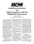
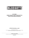
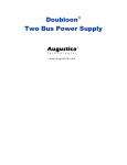
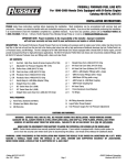
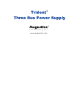
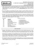
255 Liter/Hr, In Tank Fuel Pump
For 1984-1990 Chrysler Front Wheel Drive Vehicles
Catalog # 17934
INSTALLATION INSTRUCTIONS
PLEASE study these instructions carefully before installing your new In-Tank Fuel Pump for 1984-1990 Chrysler Corporation,
Front Wheel Drive vehicles. If you have any questions or problems, do not hesitate to contact our Technical Hotline at:
1-800-416-8628, from 7am-5pm PST, Mon-Fri, or via e-mail at: [email protected]. Please fill out and mail your
warranty card.
• Note: Proper installation is the responsibility of the customer. Improper or incomplete installation could result in poor
performance, related component damage, potential severe engine damage, vehicle fire, and will void your warranty. If you
do not feel comfortable installing these parts, we recommend having the installation performed by a professional mechanic.
• Description: This in-tank fuel pump replaces the factory pump and has an increased flow of 255 liters/hour (67 gph).
This in-tank upgrade pump is ideal for supporting performance improvements such as a big-bore throttle body, high
performance intake manifold, camshaft(s), turbocharger, direct port nitrous system, etc. They replace your original pump
exactly and include all necessary hardware for an easy installation:
Kit Contents:
Minimum Tools Required:
Qty.
❑1
❑1
❑1
❑1
❑1
❑1
❑1
❑1
❑1
❑3
❑2
❑2
❑2
❑1
❑2
Description
1. Lift or appropriate jack
2. OSHA-approved jackstands
3. OSHA-approved fuel transfer pump
4. OSHA-approved fuel storage containers
5. Wire stripping and crimping tool
6. Various hand tools
Description
Fuel Pump
Fuel Pump Filter (Type A)
Fuel Filter (Type B)
Fuel Filter Adapter (For Type B)
Fuel Filter Seal (For Type B)
Fuel Pump Isolator (Thin)
Fuel Pump Isolator (Thick)
Inlet O-Ring (For Type B)
Rubber Inlet Spacer (For Type B)
Fuel Hoses (Straight, Loop, & 90°)
Hose Clamps
Cable Ties
Fuel Tank O-Rings
Wiring Harness
Wiring Butt Splice Connectors
INSTALLATION NOTES
• Remember: When working on your vehicle, especially when oil or fuel is present, always work in a well ventilated area. Keep all sparks, open flames, or other sources of ignition away from the work area. Failure
to do so could result in a fire or explosion causing vehicle or property damage, personal injury, and/or death.
• Before Beginning: This installation can be accomplished using common tools and procedures. However, you should have
a basic knowledge of automotive repair and modification and be familiar with and comfortable with working on your vehicle.
If you do not feel comfortable working on your vehicle, it is recommended to have the installation completed by a
professional mechanic. Keeping a factory service manual for your vehicle on hand for reference is helpful.
©2004 Edelbrock Corporation
Rev. 2/04 - RS/mc
Page 1 of 5
Catalog #17934
Brochure #63-0224
INSTALLATION PROCEDURE
• Note: Steps shown in these instructions are intended as
a general guideline only. If you are not an experienced
mechanic, you should have a copy of your service
manual on hand. The installation procedure for replacing
your factory fuel pump is covered in full detail in your
factory service manual.
• Note: This rotary fuel injection pump will not work on
carbureted fuel systems. It is for electronic fuel injection
only.
• Note: The word “bracket” used throughout these
instructions refers to the fuel pump mounting bracket
and fuel level sender assembly.
PREPARATION
1. Make sure the engine is cool and the vehicle is on level
ground. Set the parking brake.
2. Relieve any pressure in the fuel tank by removing the
gas cap.
3. Relieve the fuel system pressure. (Note: If this
procedure is not followed, damage to the
injector(s) and/or other fuel system components
could occur.). Begin by locating and unplugging the
fuel injector wiring harness. Ground one terminal.
Apply battery voltage to the other terminal for five to
ten seconds to open the injector. This procedure is
necessary to prevent fuel from spraying when
disconnecting fuel lines. Spraying fuel could result in a
fire hazard.
4. Remove the negative (ground) cable from the battery
and position it so that it cannot make a connection to
the battery during the fuel pump installation procedure.
5. Some vehicles require removal of the fuel tank to
access the fuel pump bracket. Some require removing
the rear seat, an access panel, and possibly the trunk
liner to access the pump bracket. In those vehicles that
require fuel tank removal, see the “Fuel Tank Removal”
section. On those that do not, remove the necessary
items and gain access to the top of the fuel tank and
the fuel pump bracket and continue on to the “Bracket
Removal” section.
FUEL TANK REMOVAL
(Caution: The fuel tank can be quite awkward to
remove due to its size and weight. Obtain help
during its removal).
(Note: The following instructions may not be specific
to your particular vehicle. See your factory service
manual for specific instructions).
1. Drain the fuel tank. Use an OSHA-approved gasoline
transfer pump, and remove as much fuel as possible
through the fuel tank filler neck. Store the fuel in
approved safety containers only.
2. Lift and safely support the vehicle with approved safety
stands with enough height to gain clearance to remove
the fuel tank. If lifting only the rear of the vehicle,
remember to block the front wheels.
3. Once the vehicle is lifted and supported, an alternate
method of fuel removal may be implemented.
Determine which line is the fuel return line going back
to the fuel tank (See Fig. 1). Trace the return line back
from the injectors and remove it from the bracket.
Securely attach a hose to the exposed fuel return tube
leading into the tank, and draw the remaining fuel out
and into an approved container.
(Note: Regardless of the method used to remove fuel
from the tank, it is important to remove as much fuel
as possible before removing the tank. This is
required to help prevent fuel spillage, and injury from
excessive weight while removing the tank).
Fuel Pressure Regulator
Fuel Tank
Injector(s)
Fuel Filter
Vapor Canister
Fuel Return Line
Typical Fuel System
©2004 Edelbrock Corporation
Rev. 2/04 - RS/mc
Page 2 of 5
Fig. 1
Catalog #17934
Brochure #63-0224
FUEL TANK REMOVAL (continuation)
4. Disconnect the electrical connector at the fuel tank to
main harness connector. Disconnect the fuel lines
leading to the tank. Support and partially lower the
tank, if needed.
5. Remove the fuel filler neck, if necessary.
6. Support the fuel tank and remove the retaining straps to
allow the tank to be removed from the vehicle. Remove
the fuel tank being careful not to spill any remaining
fuel.
7. Note the condition and position of all fuel tank mounting
pads and insulators used to isolate the fuel tank from
the vehicle body. Mislocated, deteriorated, or incorrect
pads and/or insulators can cause objectionable
transmission of fuel pump noise into the vehicle.
BRACKET REMOVAL
1. Thoroughly clean all dirt and debris from the top of the
tank. Clean out any dirt from around the locking ring
and retainer. This must be done to prevent dirt or
foreign material from falling into the fuel tank while
removing the bracket.
2. Lubricate the locking ring with penetrating oil to assist
in its removal, and remove the locking ring using the
proper tool, as specified in the factory service
manual, or use another suitable method that CANNOT
potentially cause sparks resulting in fire or explosion.
Rotate the locking ring in a counter-clockwise direction
to remove it.
3. Carefully remove the bracket from the fuel tank. Use
care not to damage the float or float arm, if the float
assembly is part of the bracket (See Fig. 2).
PUMP REMOVAL
• Note: See Fig. 2 and 3 for reference during the
removal and installation procedure.
1. Remove the filter. The filter may be attached with a
clamp. If so, cut and discard the clamp. If not, remove
the filter by grasping and pulling it away from the
assembly. Discard the filter.
2. Disconnect the electrical connections to the pump. Be
sure to note the polarity of the connections. (Note: On
some applications the connectors will be
soldered to the pump’s terminals. To remove, cut
the wires as close as possible to the terminals on
the pump).
3. Remove the hose clamps, cut the rubber hose, and
remove any pump mounting hardware.
4. Invert the bracket assembly, and pull down on the fuel
pump until the inlet end clears the pump support.
Swing it to the side, and remove the pump from the
bracket’s fuel outlet tube. Save the fuel pump rubber
grommet(s) for use in mounting the new pump. Also
remove the fuel pump isolator at this time. (Note: Some
applications will require a metal band to be cut, which
retains the pump.)
5. Remove the cut hose piece from the bracket tube and
discard along with the used hose clamps. Remove the
pump to filter adapter by pressing on the retaining tabs
and discard it.
Fuel Pump Carrier
Mounting O-Ring
(Not on All Models)
Fuel Pump
Inlet Spacer
Fuel Hose
Stock Fuel Pump
Retaining Clamp
(Dotted Line)
Float Arm
Inlet O-Ring
Fuel Pump Isolator
Cable Tie
(Supplied)
Fuel Pump Carrier
Pump to Filter Adapter
Filter Seal
Filter Retaining
Clamp (Not on
All Models)
Fuel Filter
Fig. 3
Fig. 2
©2004 Edelbrock Corporation
Rev. 2/04 - RS/mc
Page 3 of 5
Catalog #17934
Brochure #63-0224
PUMP INSTALLATION
• Note: Your pump may be mounted in one of two ways,
if mounted as shown in Fig. 2, read “Type A Installation”
below. If mounted as shown in Fig. 3, continue to “Type
B Installation further down.
TYPE A INSTALLATION
1. Using petroleum jelly, sparingly lubricate the fuel outlet
tube on the bracket and the pump outlet fitting. Using
the appropriate hose (of the three supplied in the kit) for
your application, cut the hose to the proper length
needed (use your stock hose as a guide if necessary).
2. Place the supplied fuel pump isolator (thin) over the
pump.
3. Slip the rubber fuel hose and both hose clamps onto the
fuel outlet fitting on the pump and fit the pump on the
bracket. Rotate the pump as needed to obtain the best
pump outlet fitting to bracket outlet tube alignment.
4. Slip the rubber hose over the bracket outlet tube. Make
sure the hose is still fully seated against the pump.
Position and tighten the hose clamps.
5. Using one of the supplied cable ties, secure the pump to
the bracket.
TYPE B INSTALLATION
1. Using petroleum jelly, sparingly lubricate the fuel outlet
tube on the bracket and the pump outlet fitting. Using
the appropriate hose (of the three supplied in the kit) for
your application, cut the hose to the proper length
needed (use your stock hose as a guide if necessary).
2. Place the fuel hose and one hose clamp over the pump
outlet fitting. Slip the supplied fuel pump isolator (thick)
on the pump. Fit the pump into the carrier using the
stock mounting o-ring (if equipped), rubber inlet spacer
and inlet o-ring. Rotate the pump as required to achieve
best pump outlet fitting to bracket outlet tube
alignment.
3. Firmly seat the pump/carrier assembly into the filter
adapter. Reinstall any stock pump mounting hardware.
4. Reattach the pump/carrier assembly to the bracket.
5. Slip the rubber hose over the bracket outlet tube. Make
sure the hose is still fully seated against the pump.
Position and tighten the hose clamps.
©2004 Edelbrock Corporation
Rev. 2/04 - RS/mc
PUMP INSTALLATION (Continuation)
1. Connect the electrical connections using the supplied
wire harness and butt splice connectors, making sure
proper polarity is maintained.
2. Install the proper fuel filter for your application. Type A
units press onto the bottom of the fuel pump. Type B
units attach to the fuel pump filter adapter using the
supplied fuel filter seal. Make sure the filter is
positioned in the same manner as the original filter.
BRACKET INSTALLATION
1. Inspect the fuel tank for dirt and debris. If the amount
of dirt or debris is excessive, clean the fuel tank before
installing the bracket assembly.
2. Inspect the bracket to make sure it is clean and ready
for installation.
3. Use the supplied o-ring seal and place it in the groove
at the fuel tank opening.
4. Insert the bracket being careful not to damage the fuel
filter. Tighten the locking ring or bolts to secure the
bracket to the fuel tank.
FUEL TANK INSTALLATION
1. Inspect the condition and location of all tank mounting
pads, insulators and brackets. Defective, missing or
mislocated pads and insulators will cause the
transmission of excessive noise into the vehicle.
2. Inspect and correct any defects in the fuel hoses, filler
neck connections, or similar components related to the
fuel system.
3. Install the fuel tank in the vehicle and tighten the tanks
support strap bolts. Reconnect the filler neck if it was
removed. Reconnect all lines and hoses and tighten
securely. Connect the electrical connections. Make
certain that all hoses, fittings, and electrical
connections are correctly and securely attached.
4. Be sure that all fuel lines are correctly routed and
secured in any mounting brackets. Make sure the
wiring harness is installed in the original position and
secured in any wire clips or brackets, if present.
Page 4 of 5
Catalog #17934
Brochure #63-0224
WRAP UP
1. Using only equipment approved for use with gasoline,
refill the fuel tank with gasoline. (Note: Always clean
any gasoline spills immediately).
2. Inspect the fuel system for leaks. Repair any leaks
before proceeding.
3. With the ignition switch off, reconnect the fuel injector
wiring harness, and reconnect the negative (ground)
cable to the battery.
4. Start the engine and inspect the fuel lines and
connections for leaks (Note: Turn off engine and
correct any leaks before continuing.).
5. Clear any trouble codes in the electronic control unit
(ECU) that may exist as a result of the fuel pump
replacement procedure. Use the factory service
manual for assistance, if necessary.
TROUBLESHOOTING
Should the fuel pump fail to operate:
1. Check the fuel pump fuse and fuel pump relay as
outlined in the factory service manual.
2. If the pump has power and proper polarity, check the
remainder of the fuel system as outlined in the service
manual.
(Note: This pump will not remedy any
malfunctions in the fuel pressure regulator, fuel
injectors, or other fuel system problems).
Edelbrock Corporation • 2700 California St. • Torrance, CA 90503
Technical Hotline: (800) 416-8628 • Office: (310) 781-2222
E-Mail: [email protected]
©2004 Edelbrock Corporation
Rev. 2/04 - RS/mc
Page 5 of 5
Catalog #17934
Brochure #63-0224