1
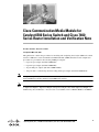
Cisco Communication Media Module for
Catalyst 6500 Series Switch and Cisco 7600
Series Router Installation and Verification Note
Product Number: WS-SVC-CMM
Last Updated: March 23, 2009
This publication contains the procedures for installing and configuring the Catalyst 6500 series switch
and Cisco 7600 series router Communication Media Module (CMM). Installation and configuration
procedures are provided for the following CMM port adapters:
•
6-port T1 port adapter (WS-SVC-CMM-6T1)
•
6-port E1 port adapter (WS-SVC-CMM-6E1)
•
24-port FXS port adapter (WS-SVC-CMM-24FXS)
•
128-port ad-hoc conferencing and transcoding (ACT) port adapter (WS-SVC-CMM-ACT)
Note
Except where specifically differentiated, the term “Catalyst 6500 series switches” includes both the
Catalyst 6500 series switches and the Catalyst 6000 series switches.
Note
Throughout this publication, except where specifically differentiated, the term supervisor engine refers
to Supervisor Engine 1, Supervisor Engine 2, Supervisor Engine 720, and the Supervisor Engine 32.
Additionally, the term Multilayer Switch Feature Card (MSFC) refers to MSFC, MSFC2, and MSFC3.
Americas Headquarters:
Cisco Systems, Inc., 170 West Tasman Drive, San Jose, CA 95134-1706 USA
Contents
Contents
This publication contains these sections:
•
Front Panel Descriptions, page 2
•
Requirements, page 6
•
Safety Overview, page 7
•
Required Tools, page 10
•
Installing and Removing the Module, page 10
•
Removing and Replacing Port Adapters, page 19
•
Verifying the Installation, page 25
•
RJ-45 Port Connector and Cabling Specifications, page 25
•
RJ-21 Port Connector and Cabling Specifications, page 27
•
Accessing the Port Adapter Ports, page 28
•
Configuring the Port Adapter Ports, page 29
•
Configuring the Port Adapter Clock Source, page 29
•
Disaster Recovery for Module Software Upgrades, page 30
•
Password Recovery, page 32
•
Regulatory Standards Compliance, page 33
•
Related Documentation, page 33
•
Obtaining Documentation, Obtaining Support, and Security Guidelines, page 33
Front Panel Descriptions
These sections describe the front panel features of the module and the port adapters:
•
CMM Module, page 2
•
6-Port T1 and E1 Port Adapters, page 4
•
24-Port FXS Port Adapter, page 5
•
Ad-Hoc Conferencing and Transcoding Port Adapter, page 6
CMM Module
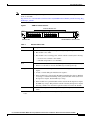
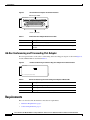
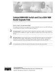
The front panel features of the modules are as follows:
•
STATUS LED—When the module powers up, it initializes various hardware components and
communicates with the supervisor engine. The STATUS LED shows the dialog with the supervisor
engine and the results of the initialization. During the normal initialization sequence, the STATUS
LED changes from off to red, to orange, and then to green. Table 1 describes the STATUS LED
operation.
•
Port adapter slots—Figure 1 and Figure 2 show the E1 port adapter in the left and middle slots, with
a blank filler plate in the right slot.
•
REAR MODULE STATUS LED—Table 2 describes the REAR MODULE STATUS LED operation.
Cisco Communication Media Module for Catalyst 6500 Series Switch and Cisco 7600 Series Router Installation and Verification Note
2
Front Panel Descriptions
Note
For information on the supervisor engine LEDs, see the Catalyst 6500 Series Switch Supervisor Engine
Guide at this URL:
http://www.cisco.com/en/US/docs/switches/lan/catalyst6500/hardware/Module_Installation/Sup_Eng_
Guide/supe_gd.html
Figure 1
CMM Front Panel Features
Interface Module slots
WS-SVC-CMM-6E1
1
2
3
4
5
0
1
2
3
4
5
ST
AT
US
RE
ST AR
AT
U
0
Communication Media Module
6-Port E1 Interface Port Adapter.
6-Port E1 Interface Port Adapter.
STATUS LED
Table 1
Color
Off
68447
WS-SVC-CMM-6E1
M
S DL
WS-SVC-CMM
REAR MODULE STATUS LED
Module STATUS LED
Description
•
The module is waiting for the supervisor engine to provide power.
•
The module is not online.
•
The module is not receiving power, which could be caused by the following:
– Power is not available to the module.
– Module temperature is over the limit1.
Red
Orange
Green
•
The module is released from reset by the supervisor engine and is booting.
•
If the boot code fails to execute, the LED stays red after power up.
•
The module is initializing hardware or communicating with the supervisor
engine.
•
A fault occurred during the initialization sequence.
•
If the module fails to download its Field Programmable Gate Arrays (FPGAs)
on startup, it continues initializing and is granted module online status from
the supervisor engine, but the LED stays orange.
•
If the module is not granted module online status from the supervisor engine,
the LED stays orange. This problem could be caused by the supervisor engine
detecting a failure in an external loopback test that it issued to the module.
•
The module is operational; the supervisor engine has granted module online
status.
1. Enter the show environment temperature mod command to display the temperature of each of the four sensors on the
module.
Cisco Communication Media Module for Catalyst 6500 Series Switch and Cisco 7600 Series Router Installation and Verification Note
3
Front Panel Descriptions
Table 2
Rear Module STATUS LED
Color
Description
Green
Port adapter in slot 4 is up and operational.
Red
Port adapter in slot 4 is shut down.
No light
Slot 4 port adapter is not located by the system.
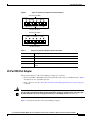
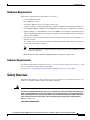
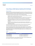
6-Port T1 and E1 Port Adapters
The front panel features of the 6-port T1 and E1 port adapters are as follows:
•
Receive port LEDs—The LEDs on the front panel indicate the status of each T1 and E1 interface.
Table 3 describes the receive port LED operation.
•
RJ-45 connectors—See the “RJ-45 Port Connector and Cabling Specifications” section on page 25
for details.
Figure 2 shows the front panels of the 6-port T1 and E1 port adapters.
Cisco Communication Media Module for Catalyst 6500 Series Switch and Cisco 7600 Series Router Installation and Verification Note
4
Front Panel Descriptions
Figure 2
6-Port T1 and E1 Port Adapter Front Panel Features
Receive port LEDs
WS-SVC-CMM-6T1
1
2
3
4
5
68448
0
6-Port T1 Interface Port Adapter
RJ-45 connectors
Receive port LEDs
WS-SVC-CMM-6E1
1
2
3
4
5
68449
0
6-Port E1 Interface Port Adapter
RJ-45 connectors
Table 3
6-Port T1 and E1 Port Adapters Receive Port LEDs
Color
Description
Green
T1/E1 interface is operational.
Red
T1/E1 receive alarm.
Yellow
T1/E1 remote alarm.
Off
T1/E1 interface has been administratively shut down, or there is no
power.
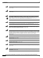
24-Port FXS Port Adapter
The front panel features of the 24-port FXS port adapter are as follows:
Warning
•
Receive port LEDs—The LEDs on the front panel indicate the status of each FXS interface. Table 4
describes the receive port LED operation.
•
RJ-21 connector—See the “RJ-21 Port Connector and Cabling Specifications” section on page 27
for details.
If the symbol of suitability with an overlaid cross appears above a port, you must not connect the
port to a public network that follows the European Union standards. Connecting the port to this type
of public network can cause severe personal injury or can damage the unit. Statement 1031
Figure 3 shows the front panel of the 24-port FXS port adapter.
Cisco Communication Media Module for Catalyst 6500 Series Switch and Cisco 7600 Series Router Installation and Verification Note
5
Requirements
Figure 3
24-Port FXS Port Adapter Front Panel Features
Receive port LEDs
98289
WS-SVC-CMM-24FXS
FXS Interface Board Adapter
RJ-21 connector
Table 4
24-Port FXS Port Adapter Receive Port LEDs
Color
Description
Green
Port is off-hook or ringing.
Off
Port is not active (connected device on-hook) or is disabled through
the CLI.
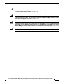
Ad-Hoc Conferencing and Transcoding Port Adapter
The front panel features of the ad-hoc conferencing and transcoding port adapter are shown in Figure 4,
and the STATUS LED is described in Table 5.
Figure 4
Ad-Hoc Conferencing and Transcoding Port Adapter Front Panel Features
Ad-hoc Conferencing and Transcoding Port Adapter
Table 5
99302
WS-SVC-CMM-ACT
Ad-Hoc Conferencing and Transcoding Port Adapter STATUS LED
Color
Description
Green
Port adapter is up and operational.
Red
Port adapter is shut down.
Off
Port adapter is not located by the system.
Requirements
These sections describe the hardware and software requirements:
•
Hardware Requirements, page 7
•
Software Requirements, page 7
Cisco Communication Media Module for Catalyst 6500 Series Switch and Cisco 7600 Series Router Installation and Verification Note
6
Safety Overview
Hardware Requirements
The hardware requirements for the modules are as follows:
•
Catalyst 6500 series switch.
•
Cisco 7600 series router.
•
252.0 Watts (6.00 A @ 42 V) of available system power
•
A Supervisor Engine 2, Supervisor Engine 720, or Supervisor Engine 32—The supervisor engine can
have an MSFC, MSFC2, or MSFC3, but the CMM does not require one for configuration or operation.
•
Supervisor Engine 32—The minimum version for the CMM is 12.4(3) and the recommended version is
12.4(7a). The minimum version for the Supervisor Engine 32 is 12.2(18)SXF4 and the recommended
version is 12.2(18)SXF4.
•
Port adapters—You can install up to three T1, E1, or FXS port adapters into slots 1 through 3 on
either base module.
You can install up to four ACT port adapters into either base module. (The internally located slot 4
is reserved for the ACT port adapter.)
Note
•
You cannot mix T1 port adapters with E1 port adapters, but any other combination of port
adapters is supported.
Module blank filler plate (WS-SVC-CMM-BLANK) for unused port adapter slots.
Software Requirements
For software requirements, see the Release Notes for the Cisco Catalyst 6500 Series and the Cisco 7600
Series Communication Media Module at this URL:
http://www.cisco.com/en/US/products/hw/switches/ps708/prod_release_notes_list.html
Safety Overview
Throughout this publication, safety warnings appear in procedures that, if performed incorrectly, can
harm you. A warning symbol precedes each warning statement.
Warning
IMPORTANT SAFETY INSTRUCTIONS
This warning symbol means danger. You are in a situation that could cause bodily injury. Before you
work on any equipment, be aware of the hazards involved with electrical circuitry and be familiar
with standard practices for preventing accidents. Use the statement number provided at the end of
each warning to locate its translation in the translated safety warnings that accompanied this
device. Statement 1071
SAVE THESE INSTRUCTIONS
Cisco Communication Media Module for Catalyst 6500 Series Switch and Cisco 7600 Series Router Installation and Verification Note
7
Safety Overview
Warning
Ultimate disposal of this product should be handled according to all national laws and regulations.
Statement 1040
Warning
Only trained and qualified personnel should be allowed to install, replace, or service this equipment.
Statement 1030
Warning
If the symbol of suitability with an overlaid cross appears above a port, you must not connect the
port to a public network that follows the European Union standards. Connecting the port to this type
of public network can cause severe personal injury or can damage the unit. Statement 1031
Warning
During this procedure, wear grounding wrist straps to avoid ESD damage to the card. Do not directly
touch the backplane with your hand or any metal tool, or you could shock yourself. Statement 94
Warning
Invisible laser radiation may be emitted from disconnected fibers or connectors. Do not stare into
beams or view directly with optical instruments. Statement 1051
Warning
Blank faceplates and cover panels serve three important functions: they prevent exposure to
hazardous voltages and currents inside the chassis; they contain electromagnetic interference (EMI)
that might disrupt other equipment; and they direct the flow of cooling air through the chassis. Do not
operate the system unless all cards, faceplates, front covers, and rear covers are in place.
Statement 1029
Warning
Hazardous voltage or energy is present on the backplane when the system is operating. Use caution
when servicing. Statement 1034
Warning
Before opening the unit, disconnect the telephone-network cables to avoid contact with
telephone-network voltages. Statement 1041
Warning
Do not work on the system or connect or disconnect cables during periods of lightning activity.
Statement 1001
Warning
Never install telephone jacks in wet locations unless the jack is specifically designed for
wet locations. Statement 1036
Cisco Communication Media Module for Catalyst 6500 Series Switch and Cisco 7600 Series Router Installation and Verification Note
8
Safety Overview
Warning
Never touch uninsulated telephone wires or terminals unless the telephone line has been
disconnected at the network interface. Statement 1037
Warning
Hazardous network voltages are present in WAN ports regardless of whether power to the unit is OFF
or ON. To avoid electric shock, use caution when working near WAN ports. When detaching cables,
detach the end away from the unit first. Statement 1026
Warning
To avoid electric shock, do not connect safety extra-low voltage (SELV) circuits to telephone-network
voltage (TNV) circuits. LAN ports contain SELV circuits, and WAN ports contain TNV circuits. Some
LAN and WAN ports both use RJ-45 connectors. Use caution when connecting cables. Statement 1021
Warning
To reduce the risk of fire, use only No. 26 AWG or larger telecommunication line cord. Statement 1023
Cisco Communication Media Module for Catalyst 6500 Series Switch and Cisco 7600 Series Router Installation and Verification Note
9
Required Tools
Required Tools
Warning
Only trained and qualified personnel should be allowed to install, replace, or service this equipment.
Statement 1030
These tools are required to remove and replace the module and port adapters:
•
Flat-blade screwdriver (for the module)
•
Number 1 Phillips screwdriver (for the screws and standoffs)
•
Antistatic mat or foam pad
•
Your own ESD-prevention equipment or the disposable grounding wrist strap that is included with
all upgrade kits, field-replaceable units (FRUs), and spares
Whenever you handle a module, always use a wrist strap or other grounding device to prevent
electrostatic discharge (ESD). For information on preventing ESD, see the “Preventing ESD” section of
the Regulatory Compliance and Safety Information publication.
Installing and Removing the Module
This section describes the procedures for installing and removing the module:
•
Installing the Module, page 10
•
Removing the Module, page 17
Installing the Module
This section describes how to install the module into the Catalyst 6500 series switch or the Cisco 7600
series router.
Note
Warning
All modules, including the supervisor engine (if you have redundant supervisor engines), support hot
swapping. You can add, replace, or remove modules without interrupting the system power or causing
other software or interfaces to shut down. For more information about hot-swapping modules, see the
Catalyst 6500 Series Switch Module Installation Guide.
During this procedure, wear grounding wrist straps to avoid ESD damage to the card. Do not directly
touch the backplane with your hand or any metal tool, or you could shock yourself. Statement 94
To install the module into the Catalyst 6500 series switch or the Cisco 7600 series router, perform these
steps:
Step 1
Make sure that you take the necessary precautions to prevent ESD damage.
Step 2
Choose a slot for the module.
Cisco Communication Media Module for Catalyst 6500 Series Switch and Cisco 7600 Series Router Installation and Verification Note
10
Installing and Removing the Module
Step 3
Verify that there is enough clearance to accommodate any interface equipment that you will connect
directly to the module ports. If possible, place modules between empty slots that contain only module
filler plates.
Step 4
Verify that the captive installation screws are tightened on all modules that are installed in the chassis.
This action ensures that the EMI gaskets on all modules are fully compressed to maximize the opening
space for the replacement module.
Note
If the captive installation screws are loose, the EMI gaskets on the installed modules will push
adjacent modules toward the open slot, reducing the opening size and making it difficult to
install the replacement module.
Step 5
Remove the module filler plate by removing the two Phillips pan-head screws from the filler plate. (To
remove a module, see the “Removing the Module” section on page 17.)
Step 6
Fully open both ejector levers on the new or replacement module. (See Figure 5.)
Step 7
Depending on the orientation of the slots in the chassis (horizontal or vertical), perform one of the
following sets of substeps:
Horizontal slots
a.
Position the module in the slot. Make sure that you align the sides of the module carrier with the slot
guides on each side of the slot. (See Figure 5.)
a.
Carefully slide the module into the slot until the EMI gasket along the top edge of the module makes
contact with the module in the slot above it and both ejector levers have closed to approximately
45 degrees with respect to the module faceplate. (See Figure 6.)
Cisco Communication Media Module for Catalyst 6500 Series Switch and Cisco 7600 Series Router Installation and Verification Note
11
Installing and Removing the Module
Figure 5
Positioning the Module in a Horizontal Slot Chassis
Insert module
between slot guides
EMI gasket
3
4
5
6
4
5
6
WS-X6K-SUP2-2GE
1
ST
AT
US
SY
ST
OL
EM
T
E
NS
CO
R
M
PW
GM
SE
Switch
100%
T
Load
CONSOLE
PORT
MODE
RE
PORT 1
PORT 2
CONSOLE
SUPERVISOR2
PCMCIA
EJECT
1%
WS-X6K-SUP2-2GE
2
ST
AT
US
SY
ST
OL
EM
T
E
NS
CO
R
PW
M
GM
SE
Switch
100%
T
Load
CONSOLE
PORT
MODE
RE
PORT 1
PORT 2
CONSOLE
SUPERVISOR2
PCMCIA
EJECT
1%
3
4
FAN
STATUS 5
6
WS-X6224
AT
US
AC
TI
VE
SE
LE
24 PORT 100FX
NE
EMI gasket
CT
XT
58569
ST
o
o
INPUT
OK
FAN
OK
OUTPUT
FAIL
INPUT
OK
FAN
OK
OUTPUT
FAIL
WS-C6500-SFM
US
AT
ST
E
TIV
AC
SWITCH FABRIC MDL
Ejector lever fully
extended
Cisco Communication Media Module for Catalyst 6500 Series Switch and Cisco 7600 Series Router Installation and Verification Note
12
Installing and Removing the Module
Figure 6
Clearing the EMI Gasket in a Horizontal Slot Chassis
WS-X6K-SUP2-2GE
T
M
LE
G
O
US
EM
M
T
AT
NS
R
ST
SE
ST
SY
CO
PW
RE
1
Switch
100%
CONSOLE
Load
CONSOLE
PORT
MODE
SUPERVISOR2
PORT 1
PCMCIA
PORT 2
EJECT
1%
WS-X6K-SUP2-2GE
NK
LI
T
M
LE
G
O
US
EM
M
T
AT
NS
R
ST
SE
ST
SY
CO
PW
RE
2
Switch
100%
CONSOLE
SUPERVISOR2
CONSOLE
PORT
MODE
NK
LI
Load
PORT 1
PCMCIA
PORT 2
EJECT
1%
NK
LI
NK
LI
3
Press down
4
FAN
STATUS 5
Press down
WS-X6224
S
TU
STA
VE
TI
AC
CT
LE
SE
24 PORT 100FX
XT
NE
6
3
4
WS-C6500-SFM
5
5
SWITCH FABIR
6
b.
Caution
ST
D MDL
AT
US
AC
TIV
E
1 mm Gap between the module
EMI gasket and the
module above it
6
58570
4
Using the thumb and forefinger of each hand, grasp the two ejector levers and press down to create
a small (0.040 inch [1 mm]) gap between the EMI gasket and the module above it. (See Figure 6.)
Pressing down too firmly on the levers will bend and damage them.
c.
While pressing down, simultaneously close the left and right ejector levers to fully seat the module
in the backplane connector. The ejector levers are fully closed when they are flush with the module
faceplate. (See Figure 7.)
Cisco Communication Media Module for Catalyst 6500 Series Switch and Cisco 7600 Series Router Installation and Verification Note
13
Installing and Removing the Module
Figure 7
Ejector Lever Closure in a Horizontal Slot Chassis
WS-X6K-SUP2-2GE
T
M
LE
G
O
US
EM
M
T
AT
NS
R
ST
SE
ST
SY
CO
PW
RE
1
Switch
100%
CONSOLE
SUPERVISOR2
Load
CONSOLE
PORT
MODE
PORT 1
PCMCIA
PORT 2
EJECT
1%
WS-X6K-SUP2-2GE
NK
LI
T
M
LE
G
O
US
EM
M
T
AT
NS
R
ST
SE
ST
SY
CO
PW
RE
2
Switch
100%
CONSOLE
SUPERVISOR2
PORT 1
PCMCIA
NK
LI
Load
CONSOLE
PORT
MODE
PORT 2
EJECT
1%
NK
LI
NK
LI
3
4
FAN
STATUS 5
WS-C6500-SFM
S
TU
STA
SWITCH FABRIC MDL
VE
TI
AC
CT
LE
SE
XT
NE
58571
6
Ejector levers flush
with module faceplate
Note
d.
Note
Failure to fully seat the module in the backplane connector can result in error messages.
Tighten the two captive installation screws on the module.
Make sure that the ejector levers are fully closed before tightening the captive installation
screws.
Vertical slots
a.
Position the module in the slot. (See Figure 8.) Make sure that you align the sides of the module
carrier with the slot guides on the top and bottom of the slot.
Cisco Communication Media Module for Catalyst 6500 Series Switch and Cisco 7600 Series Router Installation and Verification Note
14
Installing and Removing the Module
Figure 8
Positioning the Module in a Vertical Slot Chassis
Ejector lever fully
extended
WS-C6500-SFM
SWITCH FABRIC MDL
FAN
STATUS
WS-X6K-SUP2-2GE
STA
TUS
SYS
MT
OLE MG
TEM NS
R
SET
RE
PW
CO
MT
E
M
S
OL
T
MG
TU
R
NS
SE
STE
RE
PW
CO
SY
STA
WS-X6K-SUP2-2GE
SUPERVISOR2
SUPERVISOR2
ST
AT
CONSOLE
CONSOLE
AC
US
CONSOLE
PORT
MODE
PORT
MODE
WS-X6224
24 PORT 100FX
CONSOLE
TIV
E
ST
AT
US
AC
TIV
E
PCMCIA
PCMCIA
EJECT
EJECT
Switch
Switch
1%
100%
1%
100%
Load
Load
PORT 1
PORT 1
PORT 2
PORT 2
NE
XT
EMI
gasket
SE
LE
CT
63585
EMI
gasket
o
o
INPUT
OK
FAN
OK
OUTPUT
FAIL
INPUT
OK
FAN
OK
OUTPUT
FAIL
6
Insert module
between slot guides
3
4
b.
Carefully slide the module into the slot until the EMI gasket along the right edge of the module
makes contact with the module in the slot adjacent to it and both ejector levers have closed to
approximately 45 degrees with respect to the module faceplate. (See Figure 9.)
c.
Using the thumb and forefinger of each hand, grasp the two ejector levers and exert a slight pressure
to the left, deflecting the module approximately 0.040 inches (1 mm) to create a small gap between
the module’s EMI gasket and the module adjacent to it. (See Figure 9.)
Cisco Communication Media Module for Catalyst 6500 Series Switch and Cisco 7600 Series Router Installation and Verification Note
15
Installing and Removing the Module
Figure 9
Clearing the EMI Gasket in a Vertical Slot Chassis
Gap between the module
EMI gasket and the
module above it
1 mm
WS-C6500-SFM
SWITCH FABIRD MDL
US
AT
ST
E
TIV
AC
FAN
STATUS
WS-X6K-SUP2-2GE
STA
TUS
SYS
AT
US
MT
OLE MG
TEM NS
R
SET
RE
PW
CO
ST
MT
E
M
S
OL
T
MG
TU
R
NS
SE
STE
RE
PW
CO
SY
STA
WS-X6K-SUP2-2GE
SUPERVISOR2
SUPERVISOR2
WS-X6224
24 PORT 100FX
AC
E
CONSOLE
CONSOLE
TIV
PORT
CONSOLE
PORT
MODE
MODE
CONSOLE
Press left
PCMCIA
PCMCIA
EJECT
EJECT
Switch
Switch
1%
100%
1%
100%
Load
Load
NE
XT
SE
LE
PORT 1
PORT 1
Press left
CT
63586
PORT 2
PORT 2
o
o
INPUT
OK
FAN
OK
OUTPUT
FAIL
INPUT
OK
Caution
FAN
OK
OUTPUT
FAIL
Exerting too much pressure on the ejector levers will bend and damage them.
d.
While pressing on the ejector levers, simultaneously close them to fully seat the module in the
backplane connector. The ejector levers are fully closed when they are flush with the module
faceplate. (See Figure 10.)
Cisco Communication Media Module for Catalyst 6500 Series Switch and Cisco 7600 Series Router Installation and Verification Note
16
Installing and Removing the Module
Figure 10
Ejector Lever Closure in a Vertical Slot Chassis
FAN
STATUS
ST
WS-X6K-SUP2-2GE
SUPERVISOR2
AT
US
SY
ST
CO
EM
NS
O
PW
LE
R
M
M
RE
G
SE
T
S
TU
STA
T
M
LE
G
O
T
M
EM
US
R
NS
SE
ST
AT
RE
PW
CO
SY
ST
WS-X6K-SUP2-2GE
SUPERVISOR2
WS-X6224
24 PORT 100FX
T
CONSOLE
CONSOLE
VE
TI
AC
CONSOLE
PORT
MODE
CONSOLE
PORT
MODE
PCMCIA
PCMCIA
EJECT
EJECT
100%
Switch
Switch
1%
1%
100%
SE
LE
PORT 1
PORT 1
XT
Load
Load
NE
CT
63587
PORT 2
PORT 2
All ejector levers flush
with module faceplate
e.
Note
Tighten the two captive installation screws on the module.
Make sure that the ejector levers are fully closed before tightening the captive installation
screws.
This completes the module installation procedure.
Removing the Module
This section describes how to remove the module from a Catalyst 6500 series switch or the Cisco 7600
series router.
Caution
Warning
During this procedure, wear grounding wrist straps to avoid ESD damage to the module. Do not directly
touch the backplane with your hand or any metal tool, or you could shock yourself.
Invisible laser radiation may be emitted from disconnected fibers or connectors. Do not stare into
beams or view directly with optical instruments. Statement 1051
Cisco Communication Media Module for Catalyst 6500 Series Switch and Cisco 7600 Series Router Installation and Verification Note
17
Installing and Removing the Module
To remove a module from the chassis, perform these steps:
Step 1
Disconnect any network interface cables that are attached to the module.
Step 2
Verify that the captive installation screws on all of the modules in the chassis are tight.
This step assures that the space that is created by the removed module is maintained.
Note
If the captive installation screws are loose, the electromagnetic interference (EMI) gaskets on
the installed modules will push the modules toward the open slot, reducing the opening size and
making it difficult to install the replacement module.
Step 3
Loosen the two captive installation screws on the module.
Step 4
Depending on the orientation of the slots in the chassis (horizontal or vertical), perform one of the
following sets of substeps:
Horizontal slots
a.
Place your thumbs on the left and right ejector levers, and simultaneously rotate the levers outward
to unseat the module from the backplane connector.
b.
Grasp the front edge of the module, and slide the module part of the way out of the slot. Place your
other hand under the module to support the weight of the module. Do not touch the module circuitry.
Vertical slots
a.
Place your thumbs on the ejector levers that are located at the top and bottom of the module, and
simultaneously rotate the levers outward to unseat the module from the backplane connector.
b.
Grasp the edges of the module, and slide the module straight out of the slot. Do not touch the module
circuitry.
Step 5
Place the module on an antistatic mat or antistatic foam, or immediately reinstall it in another slot.
Step 6
If the slot from which you removed the module is to remain empty, install a module filler plate to keep
dust out of the chassis and to maintain proper airflow through the chassis.
Warning
Blank faceplates and cover panels serve three important functions: they prevent exposure to
hazardous voltages and currents inside the chassis; they contain electromagnetic interference (EMI)
that might disrupt other equipment; and they direct the flow of cooling air through the chassis. Do not
operate the system unless all cards, faceplates, front covers, and rear covers are in place.
Statement 1029
Cisco Communication Media Module for Catalyst 6500 Series Switch and Cisco 7600 Series Router Installation and Verification Note
18
Removing and Replacing Port Adapters
Removing and Replacing Port Adapters
Follow the procedures in this section to remove and replace the port adapters on the CMM:
•
Removing a Port Adapter from Module Slots 1 through 3, page 19
•
Installing a Port Adapter in Module Slots 1 through 3, page 22
•
Installing and Removing an Ad-Hoc Conferencing and Transcoding Port Adapter in Slot 4, page 23
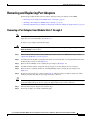
Removing a Port Adapter from Module Slots 1 through 3
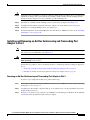
Note
When you face the module front panel, slot 1 is on the left, slot 2 is in the middle, and slot 3 is on the
right. Slot 4 is located internally. (See Figure 13.)
To remove a port adapter, perform these steps:
Warning
Hazardous voltage or energy is present on the backplane when the system is operating. Use caution
when servicing. Statement 1034
Step 1
Remove the module from the Catalyst 6500 series switch or the Cisco 7600 series router; see the
“Removing the Module” section on page 17.
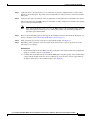
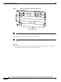
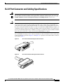
Step 2
Carefully place the module, component-side down, on an antistatic mat or foam pad with the front of the
module facing toward you. (See Figure 11.)
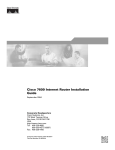
Step 3
Remove the two Phillips screws securing the port adapter. (See Figure 11.)
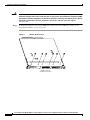
Step 4
Carefully turn the module component-side up and place it on the antistatic mat or foam pad.
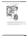
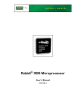
Step 5
Remove the two standoffs and the two remaining Phillips screws securing the port adapter. (See
Figure 12.)
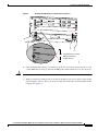
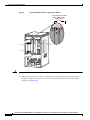
Step 6
Note the location of the two connectors in Figure 13 and remove the port adapter, taking care when
lifting up and disconnecting the port adapter from the connectors.
Tip
To unseat the port adapter from the two connectors, grasp the rear of the port adapter with one hand, and
gently but firmly pull up on the rear of the port adapter until it is free of the connectors.
Step 7
Place the removed port adapter in an antistatic bag.
Step 8
If leaving an empty slot, install a blank filler plate.
Cisco Communication Media Module for Catalyst 6500 Series Switch and Cisco 7600 Series Router Installation and Verification Note
19
Removing and Replacing Port Adapters
To install the module into the Catalyst 6500 series switch or the Cisco 7600 series router, see the
“Installing the Module” section on page 10.
6Port EI Intfc Mdl
6Port TI Intfc Mdl
S
TA
T
U
S
1
2
3
4
5
6
WS-X6600-6EI
1
2
3
4
5
6
R
S EA
TA R
T
U MD
S
L
68446
Module (Bottom View)
WS-X6600-6TI
Figure 11
WS-X6600
Step 9
Blank faceplates and cover panels serve three important functions: they prevent exposure to
hazardous voltages and currents inside the chassis; they contain electromagnetic interference (EMI)
that might disrupt other equipment; and they direct the flow of cooling air through the chassis. Do not
operate the system unless all cards, faceplates, front covers, and rear covers are in place.
Statement 1029
AVVID Services Module
Warning
Phillips screws (6)
(installed from bottom)
Cisco Communication Media Module for Catalyst 6500 Series Switch and Cisco 7600 Series Router Installation and Verification Note
20
Removing and Replacing Port Adapters
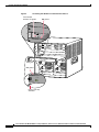
Figure 12
Module (Top View with Port Adapters Installed)
Slot 4
standoffs (2)
Slot 4 Phillips
screws (2)
Standoffs (6)
1
2
3
4
5
6
WS-X6600-6EI
1
2
3
4
5
6
S
TA
T
U
S
WS-X6600-6TI
R
S EA
TA R
T
U MD
S
L
WS-X6600
AVVID Services Module
Figure 13
6Port TI Intfc Mdl
6Port EI Intfc Mdl
68453
Phillips
screws (6)
Module (Top View with Port Adapters Removed)
Slot 4 connectors (2)
Slot 4 Phillips
screw mounting
posts (2)
Slot 4 standoff
mounting
posts (2)
Standoff mounting
posts (6)
Port adapter
connectors (6)
Slot 1
Slot 2
Phillips screw
access holes (6)
Slot 3
68452
Phillips screw
mounting posts (6)
Cisco Communication Media Module for Catalyst 6500 Series Switch and Cisco 7600 Series Router Installation and Verification Note
21
Removing and Replacing Port Adapters
Installing a Port Adapter in Module Slots 1 through 3
Note
When you face the module front panel, slot 1 is on the left, slot 2 is in the middle, and slot 3 is on the
right. Slot 4 is located internally. (See Figure 13.)
To install a port adapter in module slots 1 through 3, perform these steps:
Warning
Hazardous voltage or energy is present on the backplane when the system is operating. Use caution
when servicing. Statement 1034
Step 1
Remove the module from the Catalyst 6500 series switch or the Cisco 7600 series router; see the
“Removing the Module” section on page 17.
Step 2
Carefully place the module, component-side up, on an antistatic mat or foam pad with the front of the
module facing toward you.
Step 3
If there is a blank filler plate installed, remove it.
Step 4
Remove the new port adapter from its antistatic bag.
Step 5
Locate the slot in which you are going to install the port adapter. Note the location of the following items
(see Figure 13):
•
Two port adapter connectors
•
Two standoff mounting posts
•
Two Phillips screw mounting posts
•
Two Phillips screw access holes
Step 6
Align the port adapter with the mounting posts and mounting holes. Ensure that the connectors on the
port adapter are aligned with the connectors on the module.
Step 7
When all mounting posts and mounting holes are aligned, gently push down on the port adapter edges
to ensure that the keys on the connectors are properly aligned. If necessary, while applying pressure with
your left hand, rock the module up and down slightly with your right hand to seat the port adapter.
Tip
To seat the port adapter into the two connectors, grasp the rear of the port adapter with one hand, and
gently but firmly push down on the rear of the port adapter until it is seated in the connectors. You will
hear a distinctive “click” when the port adapter seats in the connectors.
Caution
Use care not to damage the connectors on the port adapter. If you damage a connector, you will have to
return the port adapter to Cisco for repair.
Cisco Communication Media Module for Catalyst 6500 Series Switch and Cisco 7600 Series Router Installation and Verification Note
22
Removing and Replacing Port Adapters
Caution
Using the screws or standoffs to seat the port adapter could warp the port adapter. Before you install and
tighten the securing screws, ensure that the port adapter is fully seated by visually verifying that the
bottom of the port adapter is in contact with the top of the mounting posts.
Step 8
Install the two standoffs and two Phillips screws to secure the port adapter. (See Figure 12.)
Step 9
Carefully turn the module component-side down, and place it on the antistatic mat or foam pad.
Step 10
Install the two remaining Phillips screws. (See Figure 11.)
Step 11
Install the module into the Catalyst 6500 series switch or the Cisco 7600 series router; see the “Installing
the Module” section on page 10.
Installing and Removing an Ad-Hoc Conferencing and Transcoding Port
Adapter in Slot 4
Note
Warning
The ad-hoc conferencing and transcoding port adapter is the only port adapter that can be installed in
slot 4. Slot 4 is located internally. (See Figure 13.)
Hazardous voltage or energy is present on the backplane when the system is operating. Use caution
when servicing. Statement 1034
Follow these procedures to remove and install an ad-hoc conferencing and transcoding port adapter in
slot 4:
•
Removing an Ad-Hoc Conferencing and Transcoding Port Adapter in Slot 4, page 23
•
Installing an Ad-Hoc Conferencing and Transcoding Port Adapter in Slot 4, page 24
Removing an Ad-Hoc Conferencing and Transcoding Port Adapter in Slot 4
To remove a port adapter in module slot 4, perform these steps:
Step 1
Remove the module from the Catalyst 6500 series switch or Cisco 7600 series router; see the “Removing
the Module” section on page 17.
Step 2
Carefully place the module, component side up, on an antistatic mat or foam pad with the front of the
module facing toward you.
Step 3
In Figure 13, note the location of the two slot 4 Phillips screw mounting posts. Remove the two Phillips
screws that secure the right-hand side of the port adapter.
Cisco Communication Media Module for Catalyst 6500 Series Switch and Cisco 7600 Series Router Installation and Verification Note
23
Removing and Replacing Port Adapters
Step 4
In Figure 13, note the location of the two slot 4 standoff mounting posts. Remove the two mounting posts
that secure the port adapter.
Step 5
In Figure 13, note the location of the two slot 4 connectors. Carefully remove the port adapter, taking
care when lifting up and disconnecting the port adapter from the connectors.
Tip
To unseat the port adapter from the two connectors, grasp the left-hand side of the port adapter with one
hand, and gently but firmly pull up on the port adapter until it is free of the connectors.
Step 6
Place the removed port adapter in an antistatic bag.
Step 7
Install the module into the Catalyst 6500 series switch or the Cisco 7600 series router; see the “Installing
the Module” section on page 10.
Installing an Ad-Hoc Conferencing and Transcoding Port Adapter in Slot 4
To install a port adapter in module slot 4, perform these steps:
Note
To install a port adapter in module slot 4, you need to remove the face plate from the port adapter. To
remove the face plate, position the port adapter with the face plate facing toward you, turn the port
adapter component side down on an antistatic mat or foam pad, and then remove the two Phillips screws
that secure the face plate.
Step 1
Remove the module from the Catalyst 6500 series switch or the Cisco 7600 series router; see the
“Removing the Module” section on page 17.
Step 2
Carefully place the module, component side up, on an antistatic mat or foam pad with the front of the
module facing toward you.
Step 3
In Figure 13, note the location of the two, slot 4 Phillips screw mounting posts, and note the location of
the two, slot 4 standoff mounting posts.
Step 4
Align the port adapter with the two slot 4 Phillips screw mounting posts and two slot 4 standoff mounting
posts. Ensure that the connectors on the port adapter are aligned with the connectors on the module.
Step 5
When all mounting posts and mounting holes are aligned, gently push down on the port adapter edges
that ensure that the keys on the connectors are properly aligned. If necessary, while applying pressure
with your left hand, rock the module up and down slightly with your right hand to seat the port adapter.
Tip
Caution
To seat the port adapter into the two connectors, grasp the left-hand side of the port adapter with one
hand, and gently but firmly push down on the left-hand side of the port adapter until it is seated in the
connectors. You will hear a distinctive “click” when the port adapter seats in the connectors.
Use care not to damage the connectors on the port adapter. If you damage a connector, you will have to
return the port adapter to Cisco for repair.
Cisco Communication Media Module for Catalyst 6500 Series Switch and Cisco 7600 Series Router Installation and Verification Note
24
Verifying the Installation
Caution
Using the screws or standoffs to seat the port adapter could warp the port adapter. Before you install and
tighten the securing screws, ensure that the port adapter is fully seated by visually verifying that the
bottom of the port adapter is in contact with the top of the mounting posts.
Step 6
Install the two standoffs and two Phillips screws to secure the port adapter. (See Figure 12.)
Step 7
Install the module into the Catalyst 6500 series switch or Cisco 7600 series router; see the “Installing
the Module” section on page 10.
Verifying the Installation
Enter the show module mod-num command to verify that the system acknowledges the new module and
has brought it online.
This example shows the output of the show module command with a module in slot 4:
Console>
Mod Slot
--- ---4
4
(enable) show module 4
Ports Module-Type
Model
Sub Status
----- ------------------------- ------------------- --- -------5
Communication Media Mod. WS-SVC-CMM
no ok
Mod Module-Name
Serial-Num
--- -------------------- ----------4
sad054206jc
Mod MAC-Address(es)
Hw
Fw
Sw
--- -------------------------------------- ------ ---------- ----------------4
00-01-64-46-6a-0e to 00-01-64-46-6a-17 1.0
12.2(2002012.2(20020530:100440
RJ-45 Port Connector and Cabling Specifications
Warning
Before opening the unit, disconnect the telephone-network cables to avoid contact with
telephone-network voltages. Statement 1041
Warning
Do not work on the system or connect or disconnect cables during periods of lightning activity.
Statement 1001
Warning
Never install telephone jacks in wet locations unless the jack is specifically designed for
wet locations. Statement 1036
Warning
Never touch uninsulated telephone wires or terminals unless the telephone line has been
disconnected at the network interface. Statement 1037
Cisco Communication Media Module for Catalyst 6500 Series Switch and Cisco 7600 Series Router Installation and Verification Note
25
RJ-45 Port Connector and Cabling Specifications
Warning
Hazardous network voltages are present in WAN ports regardless of whether power to the unit is OFF
or ON. To avoid electric shock, use caution when working near WAN ports. When detaching cables,
detach the end away from the unit first. Statement 1026
Warning
To avoid electric shock, do not connect safety extra-low voltage (SELV) circuits to telephone-network
voltage (TNV) circuits. LAN ports contain SELV circuits, and WAN ports contain TNV circuits. Some
LAN and WAN ports both use RJ-45 connectors. Use caution when connecting cables. Statement 1021
Warning
To reduce the risk of fire, use only No. 26 AWG or larger telecommunication line cord. Statement 1023
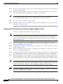
The T1 and E1 port adapter RJ-45 port connector and cabling specifications are described in this section:
•
Figure 14 shows the RJ-45 port cable connector pin orientation.
•
Table 6 describes the RJ-45 port pinouts.
Figure 14
RJ-45 Port Connector
RJ-45 (both ends)
192661
Pin 1
Pin 8
Table 6
6-Port T1 and E1 Port Adapter RJ-45 Port Pinouts
Pin1
Description
1
Receive R1
2
Receive T1
3
Not connected
4
Transmit R
5
Transmit T
6
Not connected
7
Not connected
8
Not connected
1. Table 6 lists the pinouts for the RJ-45 port connector, not the pinouts of the cable connecting to the port.
Cisco Communication Media Module for Catalyst 6500 Series Switch and Cisco 7600 Series Router Installation and Verification Note
26
RJ-21 Port Connector and Cabling Specifications
RJ-21 Port Connector and Cabling Specifications
Warning
Caution
If the symbol of suitability with an overlaid cross appears above a port, you must not connect the
port to a public network that follows the European Union standards. Connecting the port to this type
of public network can cause severe personal injury or can damage the unit. Statement 1031
Do not connect the WS-SVC-CMM-24FXS port adapter directly to a voicemail server, IVR application,
or fax server if the servers have unused wiring pairs with voltage on them. We recommend that you
connect the 25-pair cables to punch-down blocks and cross connect to the voicemail, IVR, or fax servers.
If you do not use punch-down blocks and cross connects to the WS-SVC-CMM-24FXS port adapter, you
could damage the port adapter. For example, the FLT-8 card for the Octel 250 uses every other pair for
its voice ports. The unused pairs have +36 VDC across ring-to-ground in an on-hook condition, and this
high voltage has been known to damage the WS-SVC-CMM-24FXS port adapter.
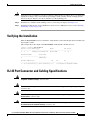
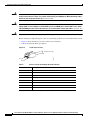
Use a standard RJ-21 Category 5 telco connector and cable to connect to the RJ-21 connector. Two types
of RJ-21 connectors are shown in Figure 15 and Figure 16. A pinout for the module’s RJ-21 connector
is provided in Table 7.
RJ-21 Telco Interface 90-Degree Cable Connector
Figure 16
RJ-21 Telco Interface 180-Degree Cable Connector
11486
11485
Figure 15
Cisco Communication Media Module for Catalyst 6500 Series Switch and Cisco 7600 Series Router Installation and Verification Note
27
Accessing the Port Adapter Ports
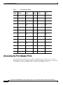
Table 7
RJ-21 Connector Pinouts
Port
Number
Connector Pin
Number
Signal
Port
Number
Connector Pin
Number
Signal
1
1
26
Ring
Tip
13
13
38
Ring
Tip
2
2
27
Ring
Tip
14
14
39
Ring
Tip
3
3
28
Ring
Tip
15
15
40
Ring
Tip
4
4
29
Ring
Tip
16
16
41
Ring
Tip
5
5
30
Ring
Tip
17
17
42
Ring
Tip
6
6
31
Ring
Tip
18
18
43
Ring
Tip
7
7
32
Ring
Tip
19
19
44
Ring
Tip
8
8
33
Ring
Tip
20
20
45
Ring
Tip
9
9
34
Ring
Tip
21
21
46
Ring
Tip
10
10
35
Ring
Tip
22
22
47
Ring
Tip
11
11
36
Ring
Tip
23
23
48
Ring
Tip
12
12
37
Ring
Tip
24
24
49
Ring
Tip
–
–
–
–
25, 50, 51, 52
GND
Accessing the Port Adapter Ports
From the module command-line interface (CLI), you identify each port adapter by interface_name
followed by slot_num/port_num. For example, to configure the first port on a 6-port T1 port adapter that
is installed in slot 2, specify T1 2/0. For the second port, specify T1 2/1, and so on.
Cisco Communication Media Module for Catalyst 6500 Series Switch and Cisco 7600 Series Router Installation and Verification Note
28
Configuring the Port Adapter Ports
Configuring the Port Adapter Ports
Configuring the module interfaces is similar to configuring the voice interfaces on other Cisco products.
module interface configuration requirements are dependent on your AVVID network requirements.
Note
The module requires a static IP address. Obtaining an IP address through a DHCP server is not
supported. You assign an IP address to the module Gigabit Ethernet backplane interface through the CLI
by using the interface GigabitEthernet1/0 command.
Configuring the Port Adapter Clock Source
The module T1/E1 port adapter clock configuration is the same as the configuration on many other Cisco
gateways. The CLI commands that are used for configuring the clock are identical to other gateways. To
set clocking for individual T1 or E1 ports, enter the clock source command in controller configuration
mode as follows:
clock source {line [primary | secondary {1..17}] | internal}
To return to the default configuration, use the no clock source command.
Note
We do not recommend that you use the clock source line command. You must enter either the clock
source line primary command or the clock source line secondary command.
If you configure the clock source for a port adapter port as primary, the Rx clock that is received from
the remote end is used to supply the clock for all module T1/E1 ports that are configured for the internal
clock on that module. Only one port adapter port can be configured as the primary clock source on a
module. If you do not configure any of the port adapter ports as the primary clock source, the internal
TDM system clock uses the free running clock on one of the port adapters.
If you configure the clock source for a port adapter port as secondary, you must also specify the priority
preference level of the source. The system automatically switches among the secondary sources to use
the highest level of preference that has the Rx clock available when the specified primary clock source
is absent.
If you configure the clock source for a port adapter port as internal, the port uses the clock that is
provided by the system. This system clock could be a module internal clock or the Rx clock from the
port that is configured as the primary clock source.
Cisco Communication Media Module for Catalyst 6500 Series Switch and Cisco 7600 Series Router Installation and Verification Note
29
Disaster Recovery for Module Software Upgrades
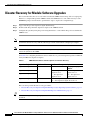
Disaster Recovery for Module Software Upgrades
This section describes how to recover in the event that the CMM software image fails to load properly.
If there is a corrupted image in the CMM bootflash, the CMM does not come online and stays at the
ROMMON prompt. You will need to perform these steps to replace the corrupted image:
Step 1
Copy a new image to the supervisor engine flash memory.
Step 2
Download the image from the supervisor engine to the CMM bootflash.
Step 3
Configure the system by using the power management bits to control which image is booted when the
CMM is reset.
Note
The downloaded image must be the same version that was previously operating on the CMM. Failure to
perform the disaster recovery with the same image version could result in corrupted port adapters.
Note
To successfully perform disaster recovery on the Supervisor Engine 720, you must have the ROMMON
version 12.2(1r)T2 on the CMM.
Use Table 8 for configuring the filename aliases and the boot or power management options for different
Catalyst 6500 series supervisor engines.
Table 8
CMM Filename Aliases and Boot Options for Disaster Recovery
Supervisor Engine Model
File Name Alias
Boot/Power Management Option
Supervisor Engine 1
slot0:ws-svc-cmm
Cisco IOS Software
Catalyst Operating System
Software
6 — For supervisor
engine in slot 1
7— For supervisor
engine in slot 2
10 — For supervisor
engine in slot 1
11 — For supervisor
engine in slot 2
Supervisor Engine 2
Supervisor Engine 32
Supervisor Engine 720
disk0:ws-svc-cmm
10 — For supervisor engine in slot 5 or 7
11 — For supervisor engine in slot 6 or 8
These sections provide disaster recovery procedures:
Tip
•
Disaster Recovery for Supervisor Engines Running Catalyst Operating System Software, page 31
•
Disaster Recovery for Supervisor Engines Running Cisco IOS Software, page 31
If the CMM image fails to load properly, a crash information file is generated and then saved in the CMM
bootflash.
Cisco Communication Media Module for Catalyst 6500 Series Switch and Cisco 7600 Series Router Installation and Verification Note
30
Disaster Recovery for Module Software Upgrades
Disaster Recovery for Supervisor Engines Running Catalyst Operating System
Software
To perform disaster recovery on systems that use the Catalyst operating system software on the
supervisor engine, perform these steps:
Step 1
Before performing the disaster recovery, remove the port adapters from the CMM.
See the “Removing and Replacing Port Adapters” section on page 19 for removal procedures.
Step 2
Enter the copy tftp [device] command to copy the golden image for the CMM to the supervisor engine
flash memory where [device] can be any flash file system on the supervisor engine.
Step 3
Enter the set filename-alias [alias-name] [device]:[golden-image] command to translate the filename of
the downloaded file.
The [golden-image] is the file to be downloaded, and the [device] can be any flash file system on the
supervisor engine. See Table 8 for configuring the appropriate [alias-name] corresponding to the
supervisor engine type in use.
Step 4
Enter the set module power down [mod] [pm_option] command to power down the CMM.
See Table 8 for configuring the appropriate [pm_option] corresponding to the supervisor engine type in
use.
Step 5
Enter the set poll disable command to disable polling.
Step 6
Enter the set module power up [mod] command to power up the CMM.
When the CMM powers up, disaster recovery is complete.
Step 7
After you complete the disaster recovery, enter the clear filename-alias [alias-name] command to
terminate the filename translation.
Step 8
Set the power management option for the CMM to zero (0).
This step is necessary to prevent the download mechanism from triggering every time that the CMM is
reset.
Step 9
Enter the set poll enable command to enable polling.
Disaster Recovery for Supervisor Engines Running Cisco IOS Software
Note
This procedure requires supervisor engine software release 12.2(18)SFX or later.
To perform disaster recovery on systems that use Cisco IOS software on the supervisor engine, perform
these steps:
Step 1
Before performing the disaster recovery, remove the port adapters from the CMM.
See the “Removing and Replacing Port Adapters” section on page 19 for removal procedures.
Step 2
Enter the copy tftp [device] command to copy the golden image for the CMM to the supervisor engine
flash memory where [device] can be any flash file system on the supervisor engine.
Cisco Communication Media Module for Catalyst 6500 Series Switch and Cisco 7600 Series Router Installation and Verification Note
31
Password Recovery
Step 3
Under the CLI Config mode, enter the tftp-server [device]:[golden-image] alias [alias-name] command
to translate the filename of the downloaded file.
The [golden-image] is the file to be downloaded, and the [device] can be any flash file system on the
supervisor engine. See Table 8 for configuring the appropriate [alias-name] corresponding to the
supervisor engine type in use.
Step 4
Under the CLI exec mode, enter the hw-module module [mod] boot [pm_option] command to set the
power management option for the CMM.
See Table 8 for configuring the appropriate [pm_option] corresponding to the supervisor engine type in
use.
Step 5
Enter the hw-module module [mod] reset command to reset the module.
When the CMM powers up, disaster recovery is complete.
Step 6
After you complete the disaster recovery, under CLI config mode, enter the no tftp-server
[device]:[golden-image] command to remove the filename translation.
Step 7
Set the power management option for the CMM to zero (0) by entering the command hw-module
module [mod] boot config-register.
This step is necessary to prevent the download mechanism from triggering every time that the CMM is
reset.
Password Recovery
Before performing the password recovery procedure, you must console into the CMM by performing
these steps:
Step 1
Note
Remove the CMM from the chassis. For removal information, see the “Removing the Module” section
on page 17.
There are two RJ-45 ports on the CMM motherboard. The second one towards the edge or end of the
motherboard is the console port.
Step 2
Connect a straight-through cable, not a regular rolled flat cable, to the console port on the motherboard.
Step 3
Remove the module directly above the CMM to allow a space for the console cable to run from the CMM
motherboard to outside of the chassis.
Step 4
Reinstall the CMM into the chassis.
Step 5
Perform the recovery procedure in Password Recovery Procedure for the Catalyst 6500/6000
SeriesSwitches Running Cisco IOS System Software to recover the password for the CMM.
Cisco Communication Media Module for Catalyst 6500 Series Switch and Cisco 7600 Series Router Installation and Verification Note
32
Regulatory Standards Compliance
Regulatory Standards Compliance
Catalyst 6500 series switches and modules comply with the regulatory standards that are listed in the
Regulatory Compliance and Safety Information for the Catalyst 6500 Series Switches publication at this
URL:
http://www.cisco.com/en/US/docs/switches/lan/catalyst6500/hardware/RC/78_12928.html
Cisco 7600 series routers comply with the regulatory standards that are listed in the Regulatory
Compliance and Safety Information for the Cisco 7600 Series Routers publication at this URL:
http://www.cisco.com/en/US/docs/routers/7600/Hardware/RCSI/78_13690.html
California Perchlorate Contamination Prevention Act (Title 22, California Code
of Regulations, Chapter 33)
The battery inside this product may contain perchlorate material, a known hazardous substance, so
special handling and disposal of this product might be necessary.
For more information about perchlorate and best management practices for perchlorate-containing
substances, see http://www.dtsc.ca.gov/hazardouswaste/perchlorate/.
Related Documentation
For more detailed installation and configuration information, see these publications:
•
Regulatory Compliance and Safety Information for the Catalyst 6500 Series Switches
•
Regulatory Compliance and Safety Information for the Cisco 7600 Series Routers
•
Catalyst 6500 Series Switch Module Installation Guide
•
Cisco 7600 Series Router Module Installation Guide
•
Catalyst 6500 Series Switch Cisco IOS Software Configuration Guide
•
Cisco 7600 Series Router Cisco IOS Software Configuration Guide
•
Catalyst 6500 Series Switch Cisco IOS Command Reference
•
Cisco 7600 Series Router Cisco IOS Command Reference
Obtaining Documentation, Obtaining Support, and Security
Guidelines
For information on obtaining documentation, obtaining support, providing documentation feedback,
security guidelines, and also recommended aliases and general Cisco documents, see the monthly
What’s New in Cisco Product Documentation, which also lists all new and revised Cisco technical
documentation, at:
http://www.cisco.com/en/US/docs/general/whatsnew/whatsnew.html
Cisco Communication Media Module for Catalyst 6500 Series Switch and Cisco 7600 Series Router Installation and Verification Note
33
Obtaining Documentation, Obtaining Support, and Security Guidelines
This document is to be used in conjunction with the documents listed in the “Related Documentation” section.
Cisco and the Cisco logo are trademarks or registered trademarks of Cisco and/or its affiliates in the U.S. and other countries. To view a list of
Cisco trademarks, go to this URL: www.cisco.com/go/trademarks. Third-party trademarks mentioned are the property of their respective owners. The
use of the word partner does not imply a partnership relationship between Cisco and any other company. (1110R)
Cisco Communication Media Module for Catalyst 6500 Series Switch and Cisco 7600 Series Router Installation and Verification Note
34