1
MONOLIGHT 3096
M i cr o p l at e L u m i n o m e t er
Operating Manual
MONOLIGHT 3096
Microplate Luminometer
Operating Manual
Revised 6/19/01
Microplate Luminometer
Contents
Contents
1.
Safety Instructions.......................................................................................1
2.
2.1
2.2
2.3
2.4
2.5
2.6
System Description......................................................................................3
Overview ..........................................................................................................3
MONOLIGHT 3096 Microplate Luminometer ...........................................6
2.2.1 Operating Components on the Front Panel.....................................7
2.2.2 Microplate Loading Compartment.....................................................8
2.2.3 Measurement Chamber ................................................................... 10
2.2.4 Light Detector...................................................................................... 10
2.2.5 Background Measurement and Subtraction................................. 11
2.2.6 Injector Compartment behind the Service Door........................... 11
2.2.7 Connections on the Rear Panel...................................................... 14
Injector Unit (optional)................................................................................ 15
Microplates................................................................................................... 16
PC.................................................................................................................. 17
Software........................................................................................................ 18
3.
3.1
3.2
3.3
3.4
3.5
3.6
3.7
3.8
3.9
3.10
3.11
Installation and Commissioning............................................................. 19
Overview ....................................................................................................... 19
Setup Site..................................................................................................... 20
Space Required.......................................................................................... 20
Unpacking.................................................................................................... 20
Connecting the Instruments..................................................................... 21
Connecting the Injector Unit ..................................................................... 23
Software Installation................................................................................... 26
Program Start .............................................................................................. 28
Instrument Configuration .......................................................................... 29
Software Registration ................................................................................ 32
First Measurement with Raw Data.......................................................... 34
4.
4.1
4.2
Structure of the Software........................................................................ 40
Software Structure ...................................................................................... 40
The Protocol Manager................................................................................ 42
4.2.1 [Protocols] Tab................................................................................. 42
4.2.2 [Instrument] Tab .............................................................................. 43
4.2.3 Further Protocol Manager Options................................................ 43
Parameter Input .......................................................................................... 44
4.3
i
Microplate Luminometer
Contents
4.4 Measurement Menu..................................................................................... 45
4.4.1 Structure of the Measurement Menu ............................................ 45
4.4.2 Working with the Measurement Menu.......................................... 46
4.5 Special Functions when Using Injectors................................................. 51
4.6 Software Functions at One Glance........................................................... 52
ii
5.
5.1
5.2
5.3
Raw Data....................................................................................................... 54
Overview......................................................................................................... 54
Measurement Protocol................................................................................ 54
Measurement................................................................................................ 60
6.
6.1
6.2
6.3
6.4
Slow Kinetics ............................................................................................... 63
Overview......................................................................................................... 63
Measurement Protocol................................................................................ 64
Measurement................................................................................................ 71
Result Display .............................................................................................. 75
7.
7.1
7.2
7.3
7.4
Fast Kinetics................................................................................................. 78
Overview......................................................................................................... 78
Measurement Protocol................................................................................ 78
Measurement................................................................................................ 84
Result Display .............................................................................................. 87
8.
8.1
8.2
8.3
8.4
8 .5
8.6
8.7
8.8
8.9
8.10
8.11
8.12
8.13
8.14
Maintenance................................................................................................. 90
Cleaning the MONOLIGHT 3096............................................................... 90
Fuse Replacement (MONOLIGHT 3096) ................................................ 91
Changing the Operating Voltage for MONOLIGHT 3096...................... 93
Taking the Instrument out of Service (for Transport)........................... 96
S e r vi c i n g a n d C l e a n i n g t h e I n j e c t o r S ys t e m ............................. 97
8.5.1 Regular Maintenance and Checks................................................. 97
8.5.2 Cleaning the Injector Unit (outside)................................................ 97
Priming/Washing/Cleaning the Injector Tubings ................................. 98
Cleaning MONOLIGHT 3096 Injector Pumps and Tubings ............... 99
Basic Cleaning Before or After Long Breaks......................................... 99
Promega Reagents Cleaning Procedure............................................101
Establishing Tubing Connections.........................................................102
Replacing Injector Tips............................................................................104
Replacing Pump Syringes......................................................................106
Replacing Fuses in the Injector Unit.....................................................107
Changing the Operating System Voltage in the Injector Unit...........109
9.
Technical Data...........................................................................................110
Microplate Luminometer
Typographical Conventions
Typographical Conventions
To make it easy for you to work with this manual and to use the
software, we will use the following typographical conventions
throughout this manual:
Button labels are printed in bold typeface inside angular brackets.
Example:
<OK>, <Start Quick Measurement>
Menu and option titles are printed in bold typeface inside square
brackets. Example: [File], [Options]
Actions are symbolized by ❏.
Enumerations are symbolized by z.
iii
Microplate Luminometer
Safety Instructions
1. Safety Instructions
The MONOLIGHT 3096 as well as the injector unit were manufactured in accordance with the safety requirements for electronic and medical measuring systems. If the law states regulations on the installation and/or operation of sample measuring
systems, then it is the operator's responsibility to adhere to
them.
The manufacturer has done everything possible to guarantee
that the equipment functions safely, both electrically and mechanically. The user must ensure that the instruments are set
up and installed in such a way that their function is not impaired.
The instruments are tested by the manufacturer and supplied in
a condition that allows safe and reliable operation.
This User’s Manual includes information and warnings that
must be observed by the user in order to ensure safe operation
of the instruments.
Please adhere to the following safety instructions when handling or operating the system:
1. The instruments may only be operated by personnel who
have been trained on the use of the systems. It is strongly
recommended that all users read this manual prior to use.
2. Use the instruments only for the designated application.
3. BD Biosciences Pharmingen assumes no liability for any
damages, including those to third parties, caused by
improper use or handling of the instruments.
4. The user may only perform the maintenance work described
in this manual.
5. Use only the parts described in this manual for servicing.
1
Microplate Luminometer
Safety Instructions
6. The instruments are live and improper handling may
cause damage.
7. Before opening the instruments, disconnect the power supply.
8. Switch off the instruments before pulling the power cord.
9. Spare fuses must match the values specified by the instrument manufacturer. The fuses must not be short-circuited or
tampered with.
10. All instruments supplied and all additional devices must be
grounded. Use three-pole grounded plugs.
11. If you can see that the units have become unsafe to use,
switch them off and disconnect them from the power supply.
12. If liquid gets inside the instruments, pull the power cord.
Clean the unit or have it cleaned by an authorized service
center.
The tests and maintenance work recommended by the manufacturer should be performed to make sure that the operator remain safe and that the instrument continues to function correctly.
Any service and maintenance work not described in the operating manual must be performed by authorized service engineers.
2
Microplate Luminometer
System Description
2. System Description
2.1 Overview
The MONOLIGHT 3096 Microplate Luminometer has been designed for the detection of chemi- and bioluminescence and for
all measurements of glow and flash luminescence on microplates, i.e. for reactions where the light remain nearly constant over a longer period of time, as well as for very fast reactions requiring at least one injection during measurement. The
MONOLIGHT 3096 was designed to be used with the add-on
injector unit for measurement requiring injection in the instrument. This unit allows injection of up to two substances in the
instrument, even during measurement.
Highly sensitive
light detector
The MONOLIGHT 3096 Microplate Luminometer is equipped
with a highly sensitive light detector. A special measuring geometry ensures high sensitivity and a dynamic range covering
more than 6 decades.
Low crosstalk
A special light guide system reduces crosstalk (light transfer
between adjacent samples) to a minimum. Crosstalk can be
reduced further by selecting suitable microplates.
Mechanical
construction
The sophisticated mechanical construction of the instrument
offers further advantages for the user:
The microplate is placed on a mobile transport unit outside the
measurement chamber and moved into the measurement
chamber for measurement by means of a highly precise control
mechanism that positions the sample wells exactly below the
photomultiplier. The separation of microplate loading compartment and measurement chamber ensures precise measurements, simple operation and little maintenance and cleaning.
3
Microplate Luminometer
Optional injector unit
System Description
The MONOLIGHT 3096 is the basic unit which can be upgraded
with the injector unit, containing 2 injectors. The MONOLIGHT
3096 is designed for working with injectors (special devices for
injector tips and tubings). In connection with the highly precise
injector unit, measurements with up to two injectors can be
performed.
Windows-based
operation
Operation and control of the MONOLIGHT 3096 Microplate Luminometer, the injectors, as well as evaluation of the measured
results take place via the Windows software Simplicity Photon
Counter (abbreviated: Simplicity PC) which was specifically designed for this field of application. It is based on MS EXCEL and
features clearly structured and intuitive user guidance.
Three
measurement
modes
Three measurement modes based on predefined measurement protocols are available:
Raw Data
Quick measurement of a microplate
Slow Kinetics
Kinetics measurement for longer light
reactions. For each data point all
samples are measured in succession.
Fast Kinetics
Kinetics measurement for short light
reactions. The trend of the light emission of the 1st sample, then the 2nd
sample etc. is measured.
The software is designed such that further measurement protocols can be integrated. This can be done by the user via EXCEL
macros in the Simplicity PC software.
The MONOLIGHT 3096 Injector Unit works with the same PC
software. Corresponding to the current instrument configuration,
additional program functions are enabled when injectors
are connected.
4
Microplate Luminometer
Fields of application
System Description
The MONOLIGHT 3096 Microplate Luminometer can be used
for these, and other applications:
• Reporter gene assays
• Immunoassays
• ATP assays
• DNA and protein assays
• PCR quantification assays
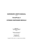
Figure 2-1:
Components of the
measuring system:
(a) MONOLIGHT 3096
Luminometer
(b) Injector unit
(c) PC (or laptop)
(d) Printer
(d)
(b)
(a)
(c)
5
Microplate Luminometer
System Description
2.2 MONOLIGHT 3096 Microplate
Luminometer
The MONOLIGHT 3096 Microplate Luminometer is a compact,
flat desktop unit with small footprint; due to its small size it can
be set up on any lab workplace.
The MONOLIGHT 3096 can work without or with up to 2 injectors.
Simply connect the MONOLIGHT 3096 injector unit to the
MONOLIGHT 3096.
To obtain reliable, consistent results, keep the following in mind:
• Do not expose instrument to direct sunlight or heavy
temperature fluctuations.
• Set instrument up in dry rooms.
• Keep microplate loading compartment free of dust and dirt.
• Clean spilled reagents inside the instrument immediately
using a clean and dry cloth.
• Open instrument door only for loading or cleaning to keep the
inside dust-free.
• Open service door next to the instrument door only after
having disconnected the instrument from main and when the
instrument door is open!
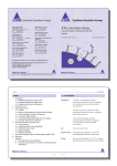
Figure 2-2
MONOLIGHT 3096
Microplate Luminometer
with injector unit
(front view)
6
Microplate Luminometer
System Description
2.2.1 Operating Components on the Front Panel
Four LED’s inform you at one glance about the current status of
the luminometer.
The LED’s from right to left:
1.
Green
2.
Red
3. + 4. Yellow
Microplate Luminometer is turned on and
ready for operation.
Measurement is running.
Do not open instrument door!
Data transfer between PC and luminometer
Instrument door
The instrument door for loading microplates is on the left instrument side. It is opened and closed by hand. When closing
the door, make sure to push it into the spring lock. An audible
click indicates that the instrument door is closed light-tight. If it i s
not closed correctly, a warning will appear on the display.
For correct measurements, the instrument door and the
service door must be properly closed so that no outside light
can enter the instrument.
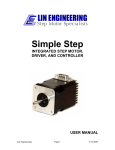
Figure 2-3:
MONOLIGHT 3096:
View with instrument
door and service
door open
Microplate
loading area
Injector head and
measurement head
Injector tubings
Injector 2
Injector 1
Velcro fastening
7
Microplate Luminometer
System Description
Detachable service door
The service door is to the right of the instrument door. You will
need this door only if you are connecting the MONOLIGHT 3096
injector unit (option) (see section 3.6).0
2.2.2 Microplate Loading Compartment
The microplate loading compartment is a compartment that i s
separated from the measurement chamber; it is accessible via
the instrument door.
In its home position, the mobile microplate transport unit i s
completely inside this compartment. After the power is turned on
and upon completion of a measurement, the transport unit
automatically moves to this position. This movement can also
be controlled via software.
The transport unit is a mobile tray accommodating the microplate. Controlled via software, the transport unit can be
moved into the measurement chamber so that the wells are exactly positioned below the photomultiplier one after the other.
The transport unit can also be moved by hand. The transport unit
comprises a spring-loaded support tray for the microplate with
a device that prevents its slipping out of place and a frame
which can be folded up.
Figure 2-4:
Microplate transport
unit with raised
holding frame
Frame
(b) Friction spring
fixing the microplate
(a) Fitting piece
for microplate or
plastic tub
Drilled hole for
transport securing
screw
(c) Spring-loaded support tray for the microplate
8
Microplate Luminometer
System Description
The spring system ensures that different microplate types, regardless of their height, will always be pushed directly against
the frame and thus as close as possible against the photomultiplier. Since the sensitivity decreases with the squared distance
to the detector, the spring system significantly increases the
sensitivity of the measuring system.
If the MONOLIGHT 3096 is operated with injectors, a small plastic tray is supplied with the instrument. Put this plastic tray into
the microplate loading compartment instead of the microplate
when priming and washing the tubing to collect the liquid escaping from the injector tips.
Keep microplate loading compartment clean
• Keep frame and loading tray clean and free of dust. If necessary, clean it with a moist cloth. Dirt will also have an adverse
effect on the measured result!
• If liquid does get under the microplate transport unit, you can
move this unit by hand or via software into the measurement
chamber, so that the bottom of the loading compartment can
be cleaned.
• Always make sure that liquid does not get into the measurement chamber.
How to insert a microplate
❏ Make sure that the service door next to the instrument door i s
closed properly!
❏ Open the instrument door of the Microplate Luminometer.
❏ Turn up the frame of the transport unit. You cannot open the
frame if the transport unit has been moved a bit to the right
towards the measurement chamber. In this case, move it by
hand all the way into the loading compartment.
❏ Place the prepared microplate onto the loading tray, such that
the A1 well is in the upper, right-hand corner.
9
Microplate Luminometer
System Description
❏ Turn down the frame and push it shut until it snaps into place
(audible click!). The microplate is held in place by the fitting
piece (Figure 2-4: (a)), by the spring on the frame at the
rear between the hinges (b) and by the spring-loaded support
tray (c).
❏ Close the instrument door. Push it shut until it clicks into
place with an audible noise. Then, the instrument is closed
light-tight.
2.2.3 Measurement Chamber
The measurement chamber is separated from the microplate
loading compartment. It is sealed light-tight only when the service door has been closed properly.
For measurement, the transport unit, with the microplate, will
move into the measurement chamber, so that the well to be
measured is exactly positioned below the photomultiplier. The
wells are measured column by column (A1 to H1, A2 to H2 ...
A12 to H12).
For information on the position of the injector tips please read
section 2.2.6. 0.
The measurement chamber is not accessible to the user. Dirt in
the measurement chamber can therefore be removed only by
authorized service engineers.
Measuring range
2.2.4 Light Detector
The light detector measures visible light in the range from 300 to
650 nm. The photons emitted by the sample are converted into
electrons and multiplied by a photomultiplier. The single pulses,
which are digitally counted, are directly proportional to the emitted light quantity.
The light emitted by the samples can only be read from above
and is – since the photomultiplier, for practical reasons (flat instrument design), is installed horizontally – reflected by a mirror
by 90° nearly without any loss.
10
Microplate Luminometer
RLU
System Description
In contrast to other physical units, luminescence is not indicated
in fixed units of measure, for example, Lumen, but in "Relative
Light Units" (RLU). Therefore, only results from the same luminometer type can be compared with each other. An RLU factor
has been defined in order to compare results from different luminometers. This factor multiplies all results. Typically, the RLU
factor is 1. Upon request, this RLU factor can be changed.
2.2.5 Background Measurement and Subtraction
The background is comprised of two components: instrument
background and reagent background.
The reagent background is obtained by measuring reagents
without any analyte. For example, with a reporter gene assays,
this measurement is of the reagents measured without cell
lysate.
2.2.6 Injector Compartment behind the Service Door
When your system includes injectors, the injector compartment
of the MONOLIGHT 3096 located behind the service door next to
the instrument door is equipped as follows:
The service door is located to the right next to the instrument
door. On the right-hand side it is held by Velcro fastening. The
plate covers the instrument area with the injector tubings, the
injector tip holder and the measurement head (see Figure 2-5).
Caution: Since the photomultiplier is exposed to incident light
when the service door is opened, you must disconnect the instrument from main before opening it to rule out damage to the
photomultiplier. For measurement the service door and the instrument door must be closed properly! Never operate the instrument with the service door removed.
• Before opening the locking plate next to the instrument door,
disconnect the instrument from wall socket and make sure
the instrument door is open!
• First, open the 2 fastening screws of the locking plate and
hold the plate at the screwed side and take it off! Otherwise,
the locking plate may get damaged!
11
Microplate Luminometer
Figure 2-5:
MONOLIGHT 3096:
View with open
instrument door
and service door
System Description
Microplate
loading compartment
Injector head and
measurement head
Injector tubings
Injector 2
Injector 1
Foam for
cable feedthrough
Velcro fastening
Insrument Door
Service Door
The injectors are arranged as shown in Figure 2-6. The
microplate moves from left to right. Injector 1 injects in the
position before the measurement position, injector 2 into the
well in the measurement position (see Figure 2-6).
Figure 2-6:
Position of injectors
above microplate
Microplate
Injector 1 in
position before
meas. position
Injector 2 in
meas. position
Measurement
head
You may take the injector head off to replace the tips and the injector tubings (see section 8, Maintenance).
12
Microplate Luminometer
System Description
Closing the Service Door
Close the service door carefully to ensure light cannot enter
the measurement chamber.
Put the tubing leading to the injector unit on the rubber foam,
so that the door is pressed into the foam and is closed
light-tight.
Align the service door exactly.
Then press the service door down firmly to close the
Velcro fastening.
13
Microplate Luminometer
System Description
2.2.7 Connections on the Rear Panel
The Luminometer rear panel includes the connection ports, the
power switch, the fuses and the cooling element.
Figure 2-7:
Rear panel of
MONOLIGHT 3096
Luminometer
I
0
1 00V
1 20V
2 30V
2 40V
Power switch Power cord
Connector
Fuses
Cooling
Element
Injector PC port
unit
data port
Connect the MONOLIGHT 3096 to the serial communication port
of the PC using the supplied 9-pin data cable (with two female
connectors).
Using the supplied cable (with two male connectors), connect
the MONOLIGHT 3096 injector unit (optional) to the 9-pin socket
of the MONOLIGHT 3096 and to the 15-pin socket on the injector
unit. Connect the instrument to wall socket via the supplied
power cable.
Line voltage and operating voltage must always match!
Observe a minimum distance of 10 cm between the back of
the instrument and the wall to allow air circulation for the
cooling element!
Voltage change, see section 8.3.
Fuse replacement, see section 8.2.
14
Microplate Luminometer
System Description
2.3 Injector Unit (optional)
The MONOLIGHT 3096 injector unit consists of two highly precise Cavro pumps and the control unit which is integrated in the
housing.
The injector unit is programmed such that the left pump is connected to the left injector tip in the MONOLIGHT 3096. In the
Simplicity PC software the left injector is Injector 1.
Figure 2-8:
MONOLIGHT 3096
with connected
injector unit (both
devices open)
Microplate
Injector head
loading area
Injector
tubings
Injector unit
Injector 2
Injector 1
Tray for reagent bottles
The right pump is connected to the right injector tip in the
MONOLIGHT 3096. In the Simplicity PC software, the right
injector is injector 2. The injector unit is closed by a plastic
cover on the front which can be taken off to connect the tubing
and to service the injector unit (see section 8). Lift the cover up
vertically from above.
Pass the injector tubings left to the MONOLIGHT 3096 and up to
the reagent bottles which are placed on the tray onto the front
side of the injector unit. Pass the tubings through the respective
openings and make sure you don’t damage or squeeze them
(see Figure 2-8).
15
Microplate Luminometer
System Description
The front side of the injector unit includes a detachable tray for
the reagent bottles. On the rear panel you have access to the
following ports:
Figure 2-9:
Rear panel of
injector unit with
connection ports
power switch
power cord connector
I
0
Voltage selection switch
115 V / 230 V
Connection to
MONOLIGHT 3096
2.4 Microplates
All 96 well microplates in standard format can be measured on
the MONOLIGHT 3096 Microplate Luminometer.
To obtain reliable, accurate results, you should only use nontransparent (opaque) microplates.
Black microplates show the lowest crosstalk, but they absorb
light, i.e. they are not suitable for samples with low light intensity.
White microplates are well suited since they reflect the light
from the samples and thus increase the sensitivity, but may
increase background.
For general use we recommend the Falcon® black opaque
microplate, Cat. No. 01-05500.
16
Microplate Luminometer
System Description
2.5 PC
Minimum requirements:
• 486 PC or laptop
• minimum 16 MB RAM
• 200 MB hard disk
• 3.5“ disk drive
• Color graphics card
• Color monitor
• Keyboard and mouse
Any printer supported by Windows.
Software requirements:
• MS Windows 95
• MS EXCEL 7.0 (optional)
17
Microplate Luminometer
System Description
2.6 Software
The MONOLIGHT 3096 Microplate Luminometer is operated by
the software package Simplicity Photon Counter (Simplicity PC)
designed specifically for this instrument.
The program comprises three levels:
Protocol Manager: management of protocols and system parameters.
Measurement parameter input: depending on the selected
measurement protocol.
Measurement menu: the measurement is performed as defined by the selected protocol type and the entered parameters
and the results are displayed.
Figure 2-10:
Structure of
Simplicity PC
software
Protocol Manager
Parameter input
18
Measurement menu
Microplate Luminometer
Installation and Commissioning
3. Installation and Commissioning
3.1 Overview
Proceed as follows to prepare your first measurement:
Step
Section
Page
Unpack and set up the instrument
3.4
20
Remove transport safety screw
3.5
21
Check operating and main voltage
3.5
21
Connect luminometer to main and power it on
3.5
21
Connect luminometer to PC
3.5
22
Check microplate transport unit manually
3.5
22
Connect injector unit
3.6
23
Connect injector tubings to pumps
3.6
23
Connect reagent bottles to pumps
24
Connect MONOLIGHT 3096 and injector unit
using a data cable
3.6
25
Check operating and main voltage
3.6
25
Connect injector unit to main and turn it on
3.6
25
Install Simplicity (PC)
3.7
26
Start Simplicity (PC)
3.8
28
Define interface in Simplicity (PC)
3.9
29
Register software
3.10
32
First measurement:
3.11
34
Enter parameters
3.11
34
Start measurement
3.11
36
19
Microplate Luminometer
Installation and Commissioning
3.2 Setup Site
The MONOLIGHT 3096 Microplate Luminometer must be set up
in a dry, fairly dust-free room and protected from direct sunlight
and significant temperature fluctuations.
Do not set it up next to a radiator.
3.3 Space Required
The luminometer is rather small (MONOLIGHT 3096 W x D x H =
39 cm x 49 cm x 13.5 cm).
The instrument rear panel must always be at least 10 cm
away from the wall or other devices to ensure that the cooling
element can work properly and you have easy access to the
power switch.
When using the injector unit (option) you must allow for an
additional 20 cm (width).
3.4 Unpacking
20
Cardboard box
The luminometer is shipped in a cardboard box that contains
two foamed inserts to protect the instrument against damage. It
also includes a smaller box with cables (power cable, connection cable PC-Luminometer) and the software. The injector unit
(option) is also delivered in a separate box. The cardboard box
is reusable. It is recommended to store the box and packaging
material for future shipping. However, boxes can be ordered
separately. Luminometer packing material is Cat. No. 551484,
and the Injector Unit packing material is Cat. No. is 551485.
Check shipment
Unpack all units and accessories and ensure the shipment i s
complete and shows no sign of transport damage. The careful
packing usually rules out transport damages. Should the
instrument or instrument parts be damaged, please inform the
shipping agent or the BD Biosciences Pharmingen immediately.
Please be careful when unpacking the instrument and removing
the foamed inserts.
Microplate Luminometer
Installation and Commissioning
3.5 Connecting the Instruments
❏ Carefully take the Microplate Luminometer
cardboard box and place it on your lab bench.
out of the
❏ Open the instrument door.
❏ Using a flat head screwdriver, unscrew the red transport
securing screw, which holds the microplate transport unit (to
the right next to the microplate frame).
❏ Keep the screw and use it again to transport the instrument!
To the left of the sample compartment, there is a threaded
hole in which the screw can be stored by screwing it in.
CAUTION: Save screw and install it again when
transporting the instrument.
Figure: 3-1:
Microplate loading
compartment with
transport securing
screw
Borehole for
transport screw
Storage of
transport screw
❏ Check if the wall socket voltage matches the operating
voltage labeled on the instrument rear panel (label and
position of the white pin on the fuse holder). If not, you must
change the operating voltage by re-plugging the voltage
selection card, so that the operating voltage matches local
voltage. See section 8.3. Check and replace the fuses, if
necessary. See section 8.2.
21
Microplate Luminometer
Installation and Commissioning
Figure 3-2:
Fuse holder with
indication of
operating voltage
Instrument rear
panel
I
0
100V
120V
PC connection
230V
240V
Connection
injector unit
100V
120V
230V
240V
I
0
Power switch
Power cord
Fuse holder
White pin at 115 V
❏ Connect the luminometer and your PC or laptop to the serial
communication port using the supplied connection cable
which is provided with female connectors on both ends.
❏ When the wall socket and operating voltage match, connect
the luminometer to the wall socket using the supplied cable.
❏ Turn the Microplate Luminometer on at the power switch (instrument rear panel). The green LED (1st from left) lights up
and signals that the instrument is ready for operation.
❏ Perform a quick hardware test to check the microplate transport unit: open the instrument door and move the microplate
transport unit by hand away from the home position. Now turn
the instrument off and on again. After power is on, the microplate transport unit moves to the home position (audible
and, with open the instrument door, visible movement). If the
transport unit does not move to this position, please contact
the Technical Service Department at 1-800-825-5832.
❏ If you have not done so yet: connect the computer to the
printer and connect both devices to the wall socket.
22
Microplate Luminometer
Installation and Commissioning
3.6 Connecting the Injector Unit
The injector unit is supplied separately. Connect the injector unit
to the MONOLIGHT 3096 and then plug it in. A few simple steps
suffice to connect the injector unit, since the injector tubings are
already installed to the injector head of the luminometer and the
other end of the tubes includes the pre-fabricated pump connection.
First, unplug the MONOLIGHT 3096 Luminometer
wall socket.
from
Put the injector unit to the right of the MONOLIGHT 3096 and
pull the locking door of the injector unit off from above to expose the injector pumps.
Open the instrument door of the MONOLIGHT 3096.
Hold the service door on the left side and pull it off the Velcro
fastening. You will find 2 rolled up injector tubings.
Figure 3-3:
Microplate loading
compartment
and injector
(both devices open)
Microplate loading area
Injector head
Injector unit
Tray for reagent bottles
Microplate Luminometer
Injector Unit
23
Microplate Luminometer
Installation and Commissioning
Pass injector tubing 1 to injector pump 1 and finger-tighten
the fitting screw in the pump head (left connection = OUT).
Proceed in the same manner with injector tubing 2. Pass the
injector tubings at the MONOLIGHT 3096 over the rubber
foam piece and at the injector unit through the openings
on the side.
Figure 3-4:
MONOLIGHT 3096
with connected
injector unit
(both devices open)
Injector head
Opening for injector tubings
to MONOLIGHT 3096
to reagent bottles
2
Injector
pump 2
1
1
2
Injector pumps
Tray for reagent bottles
OUT
IN
Cut the tubings connected to the IN ports (right) of the pumps
to the length you need and connect them to your reagent bottles. Make sure the tubings are long enough to pass them
through the openings on top of injector unit and to the bottom
of the reagent bottles standing on the tray attached to the front
of the injector unit.
Close the injector unit again by inserting the locking door vertically from above. Pass both slots on the bottom side of the
door through the openings at the bottom of the injector unit,
the two slots on top of the injector unit through the openings
on the door.
Close the service door at the MONOLIGHT 3096 very carefully
to prevent any light from entering the measurement chamber:
24
Microplate Luminometer
Installation and Commissioning
The tubings leading to the injector unit must be installed at
the foreseen place (rubber foam) so that the door is pressed
into the rubber foam.
Align the service door exactly.
Press the service door down firmly on the right hand side.
Connect the MONOLIGHT 3096 and the injector unit using the
supplied cable. Insert the 15-pin connector into the MPL port
in the injector unit.
Figure 3-5:
Rear panel of
injector unit
Power switch
Power cord
Operating
connector voltage indicator
MPL port
I
0
Check that the wall outlet voltage matches the operating
voltage labeled on the injector unit. If not, change the operating voltage as described in section 8.14.
Connect the injector unit to the wall outlet using the supplied
power cable.
CAUTION: Always turn the luminometer on first, then wait for
at least 20 seconds before turning on the injector unit.
To stabilize reagent bottles, you may use the supplied reagent bottle holders made of stainless steel.
25
Microplate Luminometer
Installation and Commissioning
3.7 Software Installation
The Simplicity software includes an automatic installation
program. The Simplicity software is compatible only with PC
format, which must have Windows 95 or better installed.
See page iii for Typographical Conventions.
Installation of Simplicity PC:
❏ Close all Windows applications.
❏ Insert program disk in drive A:
❏ Select the Windows 95 command [Run...]. The [Run] dialog
box appears.
❏ Type A:\spcsetup. This will start the setup program and
display the start screen.
❏ Click <Next>. The [Select Destination Directory] dialog box
appears and you can select the destination directory and the
directory C:\Program Files\Simplicity-PC (Figure 3-6).
❏ Click <Next> if you want to keep the defaulted directory.
Figure 3-6:
Selection of
destination
directory
26
Microplate Luminometer
Installation and Commissioning
Click <Browse> if you want to choose another directory. The
[Select Destination Directory] dialog box appears. In the
[Path:] text box, type the name of the new directory. Confirm
your entry with <OK>. The new directory is created and the
program returns to the [Select Destination Directory] dialog
box.
❏ Click <Next>. The [Ready to Install] dialog box is displayed
(Figure 3-7).
❏ Click <Next> to install the program. Upon successful
completion of the installation process, you will see a
corresponding message.
Figure 3-7:
[Ready to Install]
dialog box
27
Microplate Luminometer
Installation and Commissioning
3.8 Program Start
To start the Simplicity PC program, click the Windows 95
<Start> button, then select [Programs] and [Simplicity PC].
Simplicity PC is loaded and the Protocol Manager displayed
with two tabs (see Figure 3-8).
Figure 3-8:
Simplicity
Protocol Manager
The program is configured such that the instrument is initialized
only upon selection of the measurement menu (<Run>). In this
manner you can first define the communication port used.
You can change this presetting in the [Instrument Options]
dialog box, so that the initialization takes place when the
program is started (see section 3.9 Instrument Configuration). In
this case, communication with the luminometer is checked
when the program is loaded. When the communication has
been established, the program is fully operational. Otherwise,
you cannot call the measurement menu.
28
Microplate Luminometer
Installation and Commissioning
3.9 Instrument Configuration
For instrument configuration, select the [Instrument] tab in
Protocol Manager and make the following settings (see
Figure 3-9).
Figure 3-9:
[Instrument] tab
❏ Click <Instrument options...>. The [Instrument Options]
dialog box appears (Figure 3-10).
Figure 3-10:
[Instrument Options]
dialog box
❏ Select the communication port used in the field [Serial Port]
(COM1 or COM2). In most cases, COM 1 is the proper choice,
rarely COM 2. If you select the wrong communication port, the
error message "The instrument does not respond“ i s
displayed. In this case you must select the other port.
29
Microplate Luminometer
Installation and Commissioning
❏ [Check instrument at startup]: Select this item if you want to
initialize the Microplate Luminometer automatically any time
the program is started. Otherwise, an initialization is performed only after you select the measurement menu or click
the <Check instrument> button on this tab. Upon delivery of
the software, this item is not enabled.
❏ [Take background at startup]: Select this item if you want to
run a background measurement any time the program i s
started.
❏ Confirm your entries by clicking <OK>. The [Instrument Options] dialog box is closed, the [Instrument] tab is active (Figure 3-9).
❏ Click <Check instrument> to establish communication between PC and luminometer. If this is not possible, an error
message appears and you are prompted to check the connections and the communication port parameters. If an initialization is performed this is indicated on the status bar and
by the yellow LED lighting up on the luminometer, while the
instrument modules are being checked.
❏ Click <Read configuration>. Then the current instrument
configuration (with or without injector(s) is read in from the
Simplicity PC program.
You may carry out the following steps, if required:
❏ To run a background measurement, remove any light source
from the measurement chamber, close the loading cover and
click <Take Background>. While the background measurement is on, the red LED lights up on the luminometer. The
measured background value is displayed and remain stored
until the next background measurement is performed. It i s
also displayed in the measurement menu. Select [Subtract],
to subtract this value from the measured sample values.
30
Microplate Luminometer
Installation and Commissioning
❏ Click on <Instrument Info> on the [Instrument] tab to view the
instrument configuration (Figure 3-11). The current instrument
parameters are displayed, such as number and size of the
installed injector. The parameters cannot be changed. Please
contact BD Biosciences Pharmingen if you want to change
the RLU factor.
Figure 3-11:
[Instrument Info]
dialog box
❏ To define the subdirectory to which the measured data are to
be saved automatically, click <Options> on the [Instruments]
tab and then enter the respective path name.
31
Microplate Luminometer
Installation and Commissioning
3.10 Software Registration
The Simplicity PC software can be used for 30 days without
registration (after initial installation). During this time you will be
prompted to enter a registration password any time you call a
protocol or go to the measurement menu (see Figure 3-12).
During this time, you can close the [Registration Form] dialog
box by clicking <Run Now, Register Later> and then continue
working with the protocol.
Figure 3-12:
[Registration Form]
dialog box
If you did not enter a correct password after 30 days, you cannot
call a protocol anymore. The [Registration Form] dialog box
appears again and you either have to enter your registration
password or quit this dialog box with <Cancel>.
32
Microplate Luminometer
Installation and Commissioning
Registration
To get your registration password, contact BD Biosciences
Pharmingen, Technical Services, 1-800-825-5832.
If the [Registration Form] dialog box appears when you call a
protocol, enter your name, the company name and your
password. Then click <Register Now>. If your password entry i s
correct, you can continue working with the software. The
[Registration Form] dialog box does not come up any more.
After registration you may uninstall the program (using the
command [Uninstall]) and install an updated version without
having to enter a registration password.
33
Microplate Luminometer
Installation and Commissioning
3.11 First Measurement with Raw Data
Example of Measurement without Injectors
Since the detector needs some time before reaching its
operating temperature, the results measured just after power on
may differ slightly from those measured after the detector has
reached its operating temperature.
Therefore, we recommend that you
• start the instrument at least half an hour before running the
first measurement
• leave the instrument turned on between individual
measurements.
❏ Open the instrument door.
❏ Turn up the frame of the microplate support tray.
❏ Place the prepared microplate on the support tray so that it
sits correctly in the fitting piece and the letters are in the back.
Well A1 should be in the upper right hand corner.
❏ Turn the frame down and push it shut until it snaps into place.
❏ Check that the microplate sits correctly.
❏ Close the instrument door and push it shut until it clicks into
place.
❏ If you have not done so yet: Load the Simplicity software (See
Section 3.7). Then the Protocol Manager appears.
34
Microplate Luminometer
Installation and Commissioning
❏ In the field [Protocol type], select the protocol type [Raw Data
PC] and click <Create>. The [Raw Data PC Parameters]
dialog box appears with several tabs for input of the measurement parameters.
Figure 3-13:
[Timing] tab in the
[Raw Data PC
Parameters]
dialog box
❏ First, the [Timing] tab appears.
❏ When only one injector is used, select either, [Use
injection 1], or [Use injection 2]; if your system includes the
Injector Unit.
❏ Enter required measuring time per well. The default value is 1
second.
❏ Select the [General] tab and check the microplate type you are
using (96 wells).
❏ Select [Take background at start of plate measurement] if
you want to run a background measurement prior to the sample measurement.
35
Microplate Luminometer
Installation and Commissioning
Figure 3-14:
[General] tab in the
[Raw data PC
Parameters]
dialog box
❏ The [EXCEL (TM)] tab is not needed for the first measurements.
❏ Select the [Comment] tab if you want to enter a comment for
the measurement protocol. It appears after the protocol has
been stored in the Protocol Manager next to the measurement protocol list when the respective measurement protocol
is selected.
❏ Click <Save As...> and enter a file name in the following
dialog box. It must differ by at least one character from the file
name of the selected protocol type.
❏ Confirm the file name with <OK>. The program returns to the
Protocol Manager and shows the name of the new
measurement protocols in the field [Runable protocols].
❏ In the field [Runable protocols] in the Protocol Manager,
select the new measurement protocol and click <Run>. Then
the measurement menu is displayed (Figure 3-15).
36
Microplate Luminometer
Installation and Commissioning
Figure 3-15:
[Raw Data PC]
Measurement menu
Measuring the entire microplate
❏ Click the
button.
Measuring a selected area
❏ Click on the first well of the area you want to measure and
with the mouse button held down, drag the cursor over the
wells to be measured. These wells are highlighted by a dark
color (Figure 3-16). Release the mouse button when the
desired area is marked.
Figure 3-16:
Selected well area
❏ Click the
button. Then the selected wells turn white, the
others are gray-shaded (Figure 3-17).
37
Microplate Luminometer
Installation and Commissioning
Figure 3-17:
Defined well area
❏ The marked area is cleared again when you define a new
area with the mouse and click the
button again.
Running a measurement
❏ Click
to start the measurement. The defined measurement procedure begins: the individual wells are selected in
succession and measured using the predefined measurement time. The results are displayed in the well matrix on the
screen. These are net results, provided a background measurement has been carried out prior to the measurement
(display of the BG values in the field [Background]) and the
item [Subtract] has been activated.
❏ Click
to enter a comment for the measurement which will
be printed out in the report. This opens the [Measurement
Comment] dialog box and you can enter your text.
❏ Click
to save the measurement data and then enter a
file name.
38
Microplate Luminometer
Installation and Commissioning
Next measurement
❏ To run the next measurement with the same measurement
protocol, click
(New measurement). The next measurement can be started immediately when the data of the
preceding measurement have already been saved. Otherwise
you will be prompted to save this data. If you have stored the
data or if you have replied <No>, the screen is cleared for the
next measurement and the icon buttons are enabled again.
❏ To run the next measurement with another measurement
protocol, select [Exit] on the [File] menu. If the data of the
preceding measurement have not yet been stored you will be
prompted to save this data. After you have stored the data or if
you have replied <No>, the program returns to the Protocol
Manager and you can select a new measurement protocol.
39
Microplate Luminometer
Structure of the Software
4. Structure of the Software
4.1 Software Structure
The Simplicity software comprises three levels:
1. The Protocol Manager which is displayed after program
startup is the program’s switchboard featuring the following
functions:
•
•
•
•
•
•
•
Create measurement protocols: <Create...>
Edit measurement protocols: <Edit...>
Delete measurement protocols: <Delete>
Select measurement menu: <Run...>
Load data file: <Retrieve Data>
Define instrument parameters: [Instrument] tab
Define directory for measured data: <Options>
(see section 4.2)
2. Input of measurement parameters. To enter measurement
parameters, either create a new measurement protocol in the
protocol manager (<Create...>) or edit an existing measurement protocol (<Edit...>). The respective protocol is loaded
and can be filled out and saved for later measurements (see
section 4.3).
3. The measurement menu is structured depending on the selected protocol type. Here, the measurement is started and
executed. At the same time, the measurement menu is the
switchboard for display and further processing of the measured results: result display, graphical presentation and export
of the data into EXCEL (see section 4.4).
Section 4.6 includes an overview of the program functions.
40
Microplate Luminometer
Structure of the Software
Protocol Manager
Figure 4-1:
Structure of
Simplicity (PC)
program
Create meas.
protocol
Save
Measurement
menu
Graph display
EXCEL
41
Microplate Luminometer
Structure of the Software
4.2 The Protocol Manager
After startup of the software, the Protocol Manager appears and
you can create and edit protocols and start measurements:
Creating instrument parameters
Figure 4-2:
Simplicity Protocol
Manager
Protocol
templates
User-created
measurement protocols
Retrieve
measured
data
Define subdirectory for
measured
data
Comment on
highlighted
protocol
Exit
program
4.2.1 [Protocols] Tab
[Protocol types]
The implemented protocol types are displayed in this field. Each
protocol type includes a group of parameters for a special
measurement method such as the measurement time, but without any values. The name of a protocol type therefore refers to
the measurement method for which it is used, for example
[Slow Kinetics] for kinetics measurements with light emission
over a longer period of time. A protocol type always serves a s
template for a measurement protocol which includes certain parameters defined by the user. Based on one protocol type, you
can set up as many measurement protocols with different parameters desired.
To create a measurement protocol, click <Create>, i.e., select a
protocol type as template, enter the required parameters and
save it under a new name. The program stores measurement
protocols automatically in the field [Runable protocols] and lists
them in alphabetical order. The name of a measurement
42
Microplate Luminometer
Structure of the Software
protocol must not be identical with the name of the protocol type,
but should refer to the measurement method. You can enter a
comment for each measurement protocol; it appears in the field
next to the measurement protocol list, when the respective
protocol has been selected (see Figure 4-2).
[Runable protocols]
The available measurement protocols are listed in alphabetical
order. They are based on a selected protocol type and include
the parameters defined by the user. The following buttons are
available to edit measurement protocols:
<Run...>
Opens the measurement menus to start a measurement with the selected protocol.
<Edit...>
Shows the selected measurement protocol and
lets you change it.
<Delete>
Deletes the selected protocol.
4.2.2 [Instrument] Tab
On this page, enter and view the instrument parameters and initialize the instrument. Only the buttons <Instrument options...>,
<Check instrument> and <Take Background> are important for
the user.
<Instrument options...> takes you to the [Instrument Options]
dialog box to define the instrument communication port (see
section 3.9 Instrument Configuration).
Further Protocol Manager Options
<Retrieve Data> Load and display stored measurement data.
<Options>
Select subdirectory to which the measured
data are to be saved.
<Exit>
Exit program.
43
Microplate Luminometer
Structure of the Software
4.3 Parameter Input
Select a protocol type and click <Create> or select a measurement protocol and click <Edit> to display the respective measurement protocol for parameter input (Figure 4-3). The title bar
shows the file name of the protocol. This dialog box comprises
several tabs. To open a tab, simply click on it.
Protocol file name
Figure 4-3:
Measurement protocol
[Slow Kinetics
Parameters],
[Plate Timing] tab
As soon as you have entered your parameters, click <Save
As...> to save the protocol under a new name or click <Save> to
save it under the old name. The stored measurement protocol i s
then filed in the field [Runable protocols].
A new measurement protocol does not include the <Save> button; the file still bears the name of the protocol type which may
not be used for saving this protocol.
44
Microplate Luminometer
Structure of the Software
4.4 Measurement Menu
Upon selection of the measurement protocols in the Protocol
Manager and clicking on <Run...>, the program displays the
measurement menu which is structured according to the selected measurement method.
At this point the luminometer is initialized, if this has not been
done yet (see section 3.9).
4.4.1 Structure of the Measurement Menu
Title bar with file name and
name of measurement method
Menu bar Tool bar
Figure 4-4:
Measurement menu
[Raw Data PC]
Presentation of microplate
as sample matrix
Status bar
Title bar
shows the measurement method.
Menu bar
shows the titles of the pulldown menus.
Tool bar
shows the tool buttons you can work with in
the displayed measurement mode.
45
Microplate Luminometer
Structure of the Software
Measurement
Parameters
The date, time, background, injectors used
and the measurement time are displayed
below the toolbar. You can choose if the
displayed background value is to be subtracted from the measured values.
Sample matrix
The microplate is depicted as a sample
matrix with each well being represented by
a box. Here you can select the wells to be
measured. For Raw Data, the measured
results are entered in the respective boxes,
for Slow Kinetics and Fast Kinetics measurements are displayed in a separate table.
Status bar
The status bar keeps you informed about
the status of the sample drawer and the
next operating steps in accordance with the
selected measurement protocol.
4.4.2 Working with the Measurement Menu
This section briefly describes all functions that all measurement
methods have in common. The functions which all measurements with injectors have in common (for example, priming) will
be discussed at the end of this section.
All important functions in the measurement menu can be selected via tool buttons. Buttons or menu items that cannot be
selected are dimmed. Some buttons are dimmed (gray), for example, when a measurement is running or no contact has been
established with the luminometer or the data of the last measurement have not yet been saved. In all these cases a measurement cannot be started.
46
Microplate Luminometer
Structure of the Software
Autosave Function
Upon selection of this function, the results are automatically
saved to files. The file names comprise an abbreviation of the
measurement method (RD, SK and FK) and a consecutive
number. This ensures fast storage of the measured data according to the selected methods.
Before starting a measurement, first select the [Autosave] function on the [Options] menu (✔= active). It will remain active until
you deselect it again.
Selection of the sample area to be measured (see also page 39)
All wells of the microplate
As default, all wells of a microplate are selected for the following
, the entire mimeasurement. When you click the Start button
croplate is measured.
Selecting partial areas
If you want to measure one segment of the microplate, click the
button, mark the desired area with the cursor. Then click the
button again to confirm the selection and to exit the select
mode (see section 4.4). The wells selected for measurement
are depicted white on the screen, the others shaded gray.
Background measurement
Before starting a measurement, you can run a background
measurement by pressing the BG button. The result is displayed in the [Background] field. Select [Subtract] if you want to
subtract the background of the individual sample values.
Measurement start
Measurement of the microplate or the selected area starts after
pressing the Start button (green signal light), when the instrument door is closed. The red LED lights up on the instrument.
The Start button is dimmed when a measurement is running,
when there is no contact with the luminometer or when the data
of the last measurement have not yet been saved. In all these
cases, a measurement cannot be started.
47
Microplate Luminometer
Structure of the Software
If the instrument door is not closed, a warning appears informing you about the current measurement mode:
Close the instrument door and click <Repeat> or <OK>. Then
the measurement starts.
Measurement procedure
The measurement procedure varies depending on the selected
measurement method.
Measurement end
The measurement is over when all selected wells have been
measured. In the autosave mode the measured results are
stored automatically and the measured values cleared from the
screen. If the autosave mode is not active the measured values
remain displayed and can be stored later.
Measurement stop
Press the Stop button (red signal light) to stop the measurement. The results measured up to now can be stored.
Comment
To enter a comment for the measurement, click the Comment
button. The text entered in the [Measurement Comment] dialog
box is printed in the report and saved to the data file.
Save
You can save the measured results under any name by clicking
the Save button.
If you want to quit the measurement menu without saving the
data or if you click the button for new measurement
be prompted to save the data.
, you will
In the autosave mode, each measurement is stored automatically and the file name (RD, SK or FK) is provided with a consecutive number.
48
Microplate Luminometer
Structure of the Software
New measurement
a) When using the same measurement protocol:
In the autosave mode you can immediately start a new measurement as soon as a measurement is finished. You can keep
the selected area or define a new area as describe above.
In the normal save mode, the measurement is cleared for the
button (= new
next measurement when you click on the
measurement), if the measured data of the last measurement
have already been saved. Otherwise you may continue only after
you have either saved the data or confirmed that you do not want
to save the data. Clearing means that the measured data of the
previous measurement are cleared from the screen and all tool
buttons are active again. You may keep the selected area or define a new one as describe above.
b ) When using a new measurement protocol:
To load a new protocol you must to exit the measurement menu
via [File] / [Exit]. The program changes to the Protocol Manager
and you can select another measurement protocol and start
with <Run>.
Excel Transfer
To transfer the measured data to Excel, click the
button. Excel is started – provided it is installed on your PC - and the
measured data are imported into an Excel spreadsheet.
49
Microplate Luminometer
Structure of the Software
Figure 4-5:
Presentation of the
measured results in
an Excel spreadsheet
Printout
Click the Print button to print the measured data in a tabulated
form. If you have entered a comment it will be printed as well.
To set the print parameters, select [Print Setup...] on the [File]
menu.
To view and edit the layout before printing, select [Print Preview]
on the [File] menu.
Copy
50
Copy measured data to the clipboard. Select the respective data
with the cursor and click on this tool button. You may then paste
the copied data into another Windows program.
Microplate Luminometer
Structure of the Software
4.5 Special Functions when Using Injectors
Initialization
Prior to the first measurement (after starting the programs), you
must initialize the injector unit by clicking the Initialize button.
Otherwise, no measurement can be started. Then you are
prompted to place a plastic tub into the microplate loading compartment (instead of a microplate) to collect any spilled liquid. As
soon as you have placed the plastic tub, click <OK>. The end of
the initialization process is again indicated in a window, while
the pumps perform several lifting motions.
Take the plastic tub out and insert the microplate to be measured; then click <OK> in the message window. Start the measurement by clicking the green signal light.
Priming
Washing and priming of the injector tubings is possible only
when the injector unit has been initialized. Make sure you have
placed an empty plastic tub in the microplate loading compartment to collect spilled liquid!
Click on the Prime button to open the Parameters for Priming
Injectors dialog box.
Select the injector (Inj. 1 or Inj 2).
For each injector, enter the volume/strokes (ml) and the number
of strokes.
The programmed priming process starts as soon as you click
<OK>. When the priming process is finished you can start the
measurement using the selected measurement protocol.
Stopping the Priming Process
You may stop a started priming process any time by clicking the
Stop Priming button.
51
Microplate Luminometer
Structure of the Software
4.6 Software Functions at One Glance
The Simplicity software is a Windows 95 application and i s
therefore operated according to the Windows conventions.
To simplify operation, you can use tool buttons (icons) in the
measurement menu; in this case you do not need to open a
pulldown menu.
The tool buttons and their functions:
Button
Function
Pulldown-menu -> Option
Save measured data
[File] -> [Save (as)]
Clear sample matrix for new
measurement
[File] -> [New]
Copy measured data
[Edit] -> [Copy]
Show measured data in Excel
[Edit] ->[Send to Excel]
Enter comment on measurement
[Edit] -> [Measurement
Comments]
Button for selection of wells
[Measure] -> [Select wells
to Measure]
Print
[File] -> [Print]
Start measurement
[Measure] -> [Start
Measurement]
Stop measurement
[Measure] -> [Stop
Measurement]
Move microplate to home position
[Measure] -> [Move home]
Run background measurement [Measure] -> [Get
Background]
52
Microplate Luminometer
Structure of the Software
Tabulated presentation of results
[Window] -> [Show Table]
Graphical presentation of results
[Window] -> [Show Kinetics
Graph]
Graphical presentation of individual wells
[Window] -> [Graph wells]
Zoom function
[Window] -> [Zoom]
Windows arranged horizontally
[Window] -> [Tile Horizontal]
Windows arranged vertically
[Window] -> [Tile Vertical]
Initializing the injectors
Washing/Priming the injector
tubings
Stopping the washing / priming
process
Options without buttons:
[Options] -> [Autosave]
If this item is active (indicated by a ✔), the measured data are
saved automatically upon completion of the measurement. The
measured data are saved according to the measurement
method used to consecutively numbered files and cleared from
the screen. Thus, you can start another measurement using either
the selected sample area or defining a new area immediately.
[File] -> [Exit]
Exit the measurement menu and return to the Protocol Manager.
File names of autosave files:
Raw Data
Slow Kinetics
Fast Kinetics
RD1.TXT, RD2.TXT ... RDQMxxx.TXT
SK1.TXT, SK2.TXT ... SKxxx.TXT
FK1.TXT, FK2.TXT ... FKxxx.TXT
53
Microplate Luminometer
Raw Data
5. Raw Data
5.1 Overview
The function Raw Data allows you to run measurements with
minimum preparations. The measurement starts as soon a s
you have entered the measurement parameters and defined the
wells to be measured. Then the measured data are transferred
to the PC every 0.2 seconds and the averaged results are displayed on the screen in a sample matrix. The measured results
can then be imported into EXCEL for further processing.
5.2 Measurement Protocol
Creating a new
measurement
protocol
In the Protocol Manager, select the protocol type [Raw Data]
and click <Create...>.
Editing an existing
measurement
protocol
In the Protocol Manager, select an existing measurement protocol and click <Edit...>.
The [Raw Data PC Parameters] dialog box appears, with the file
name of the measurement protocol being displayed on the title
bar. This dialog box comprises several tabs for input of the
measurement parameters (Figure 5-1).
Figure 5-1:
[Timing] tab in the
[Raw Data
PC Parameters]
dialog box
54
Microplate Luminometer
Raw Data
[Timing] tab (without injectors)
[Measurement duration]: Enter the measurement time per well.
The default value is 1 second.
[Timing] tab (with injectors)
Except for the measurement time, you enter the parameters for
the individual injections here:
When using one injector:
Select injector (inj. 1 or inj. 2) by clicking on the respective box.
You can then enter the injector parameters.
Injector 1
Injector 2
Please note: Injector 1 injects into the well before the measurement position, injector 2 in the measurement position.
[Volume]: Enter the injection volume in µl (via keyboard or by
clicking on the arrow buttons).
Microplate
Or:
[Injection 1 to measurement delay]: Enter the delay time between the injection of injector 1 and the start of the measurement in seconds. The hardware-dependent minimum value of
2.05 seconds is defaulted and can be increased.
[Injection 2 to measurement delay]: Enter the delay time between the injection of injector 2 and the start of the measurement in seconds. The minimum value of 0 seconds is defaulted
and can be increased.
Figure 5-2:
[Timing] tab. Selection of injector 1
55
Microplate Luminometer
Raw Data
When using two injectors:
Select both injectors. The following dialog box appears:
Figure 5-3:
[Timing] tab.
Selection of
injector 1 and 2
[Volume]: Enter the injection volumes in µl (via keyboard or by
clicking on the arrow buttons).
Injector 1
Injector 2
[Injection 1 to injection 2 delay]: Delay time between the injections of injector 1 and 2. The hardware-dependent minimum
value of 2.05 seconds is defaulted and can be increased (tP-I).
[Injection 2 to measurement delay]: Enter the delay time between the injection of injector 2 and the start of the measurement in seconds. 0 second is defaulted and can be increased (tM-I).
Example: Programming a measurement with 2 injections:
P
I
M
tPtM-I
TM
56
=
=
=
=
=
=
pre-injection
injection
measurement
delay between pre-injection and 2nd injection
delay between 2nd injection and start of measurement
duration of measurement
Microplate Luminometer
Raw Data
Dual Measurement
The Simplicity 1.0 software includes four pre-programmed dual
luciferase reagent (DLR) protocols. Dual measurement protocols
cannot be created using
the Simplicity
1.0
software, The "Use dual measurement" option is grayed-out in
the screen seen in Figure 5.3.
[General] tab
Select the type of microplate you are using (96 wells).
Select [Take background at start of plate measurement] if you
want to run a background measurement prior to the sample
measurement.
Figure 5-4:
[General] tab in the
[Raw Data PC
Parameters]
dialog box
57
Microplate Luminometer
Raw Data
[EXCEL (TM)] tab
Create an EXCEL macro for control of a measurement procedure by making the necessary entries here. Prerequisite is that
EXCEL 7.0 is installed on your PC and running (Figure 5-5).
Figure 5-5:
[EXCEL (TM)] tab
[Auto-send to...]
Upon completion of the measurement, the
Excel macro is automatically sent to the
Excel program and executed there.
[Workbook]
Selection of workbook. Click on <...> to display the browser. The subdirectory Simplicity\workbook is defaulted.
[At cell]
The measured data are read starting at this
cell of the Excel spreadsheets.
[Excel(TM) macro] Entry of an Excel macro.
58
Microplate Luminometer
Raw Data
[Comment] tab
The comment entered here appears, after the protocol has been
saved, in the Protocol Manager next to the measurement protocol list when the respective measurement protocol is selected.
Figure 5-6:
Input field for a
comment on the
measurement
protocol
The following buttons appear on all tabs of the entire measurement protocol:
<Save As...>
is selected to define a new file name. This i s
necessary in order to create a new measurement protocol, or to save an existing measurement protocol under a new name. Clicking on
this button opens the [Save As...] dialog box.
Enter a file name which differs by at least one
character from the file name of the selected
protocol type. As soon as the protocol has been
saved, the program returns to the Protocol Manager and shows the name of the new measurement protocols in the field [Runable protocols].
<Save>
Saves the parameters in the existing measurement protocol file. After you have saved the protocol,
the
program
returns
to
the
Protocol Manager.
59
Microplate Luminometer
Raw Data
<Cancel>
The changes are disregarded and the old values
are still valid. The program returns to the Protocol Manager.
5.3 Measurement
As soon as you have selected measurement protocol type Raw
Data PC and you have clicked <Run>, the program changes to
the [Raw Data PC] measurement menu. Communication with
the Microplate Luminometer is established (if this has not been
done during program start). “Initializing instrument” appears on
the status bar and the yellow LED lights up.
Figure 5-7:
Measurement menu
[Raw Data PC]
Status bar
Please note: Before running a measurement, if desired, select
the autosave mode. Select this function in the [Options] menu.
Procedure (without injections)
❏ Insert microplate correctly into the luminometer and close
cover.
❏ Run background measurement, if necessary (
❏ Select the wells to be measured (
❏ Start measurement (
60
).
).
).
Microplate Luminometer
Raw Data
Procedure with injections
Select the wells to be measured.
Place plastic tub in plate loading compartment.
Initialize injectors (
).
). Insert microplate.
Prime injector tubing, if necessary (
Insert microplate correctly in luminometer and close door.
If necessary, run background measurement (
Select the wells to be measured (
Start measurement (
Measurement start
).
).
).
Measurement of the microplate or the selected area starts after
pressing the Start button (green signal light), when the instrument door is closed.
The Start button is dimmed (gray) when a measurement is running, or no communication has been established with the luminometer, or the data of the last measurement have not yet been
saved. In all these cases, no measurement can be started.
If the instrument door is not closed, a message is displayed indicating the current measurement mode:
Close the instrument door and click <Repeat> or <OK>. Then
the measurement will be started.
Measurement
procedure
Any programmed injections will be performed and the selected
wells are measured one after the other. The results of the individual samples are entered into the respective fields.
61
Microplate Luminometer
62
Raw Data
Measurement end
The measurement is finished as soon as all selected wells
have been measured. In the autosave mode, the measured results are automatically saved and the measured values cleared
from the screen. If the autosave mode is not active the measured values remain displayed and can be saved.
Measurement stop
Push the Stop button (red signal light) to stop a measurement.
The results measured so far can be stored.
Microplate Luminometer
Slow Kinetics
6. Slow Kinetics
6.1 Overview
In the measurement mode Slow Kinetics the trend of the light
emission of samples is measured. To this end, the number of
data points must be defined. The measurement starts after input of the measurement parameters and definition of the wells
to be measured. Then all samples for data point 1 are measured in succession and the averaged results displayed in a table. Then the measurement is carried out for data point 2 etc.
The data can be presented as a graph or in a table or imported
into an EXCEL spreadsheet for further processing.
63
Microplate Luminometer
Slow Kinetics
6.2 Measurement Protocol
Creating a new
measurement
protocol
In the Protocol Manager, select the protocol type [Slow Kinetics]
and click <Create...>.
Editing an existing
measurement
protocol
In the Protocol Manager, select an existing measurement protocol and click <Edit...>.
The [Slow Kinetics Parameters] dialog box with several tabs i s
displayed and you can enter the measurement parameters
(Figure 6-1).
Figure 6-1:
[Plate Timing] tab in
the [Slow Kinetics]
dialog box
[Plate Timing] tab
The following mutually dependent parameters must be taken
into account for the kinetics measurement:
• the number of data points
• measurement time per well = 1 sec
• the number of samples to be measured
• the number of injections per well
• the delay time between injection(s) and measurement time
• the expected duration of the light emission of the samples
64
Microplate Luminometer
Slow Kinetics
• the time required for the movement of the microplate transport
unit. This is in turn dependent upon the position of the samples to be measured. If the samples are located all over the
microplate, more time is needed than for an arrangement in
one row or in one corner of the microplate (at least 1 sec).
Please note: for each data point (interval), all selected samples are measured in succession.
Calculation of actual times:
Total duration of experiment: Duration of the interval x number
of data points.
Duration of interval:
(Delay times + measurement time
+ feed time) x number of samples.
[Total duration of experiment]
Total duration of measurement (including movement of the microplate transport unit)
[No. of repeat plate measurement]
Number of data points.
[Interval]
The program shows the interval period calculated from the two
previous parameters. During this time, the defined samples
should be measured once. The minimum duration should be
number of samples x 2 sec.
Parameter input
The interval is defined by changing the parameters [Total duration...] and [No. of repeat...]. The program calculates the inputs
in the dialog box according to the formula
[Interval] = [Total duration...]/[No. of repeat...]
This demonstrates that the total duration must be increased
when the interval is to be extended while the number of data
points stays the same.
Please note: Use intervals that are long enough to allow for the
microplate transport.
65
Microplate Luminometer
Slow Kinetics
The program automatically corrects for intervals that are too
short:
If you have defined an interval that is too short, the program
calculates the required intervals using the new time actually
required, and displays it on the screen after measurement of the
1st data point. The measurement can then be continued with the
new parameters or aborted. For example, if you start a
measurement with 2 samples using the parameters from Figure 6-2, the time data is changed upon completion of the 1st interval: depending on the position of the selected wells the data
points are e.g. 0 s, 6 s, 12 s (instead of 0 s, 1 s, 2 s).
[Well Timing] tab (with injectors)
Except for the measurement time, enter the parameters for the
individual injections here:
When using one injector:
Injector 1
Injector 2
Select the injector (inj. 1 or inj. 2) by clicking on the respective
box. Then enter the injector parameters.
Please note: Injector 1 injects into the well before the measurement position, injector 2 in the measurement position.
Microplate
[Volume]: Enter the injection volume in µl (via keyboard or by
clicking on the arrow buttons).
[Injection 1 to measurement delay]: Enter the delay time between the injection of injector 1 and the start of the measurement in seconds. The hardware-dependent minimum value of
2.05 seconds is defaulted and can be increased.
Or:
66
[Injection 2 to measurement delay]: Enter the delay time between the injection of injector 2 and the start of the measurement in seconds. The minimum value of 0 seconds is defaulted
and can be increased.
Microplate Luminometer
Slow Kinetics
Figure 6-3:
[Well Timing] tab.
Selection of
injector 1
When using two injector:
Select both injectors. The following dialog box appears:
Figure 6-4:
[Well Timing] tab.
Selection of
injector 1 and 2
67
Microplate Luminometer
Slow Kinetics
[Volume]: Enter the injection volumes in µl (via keyboard or by
clicking on the arrow buttons).
Injector 1
Injector 2
Microplate
[Injection 1 to injection 2 delay]: Delay time between the injections of injector 1 and 2. The hardware-dependent minimum
value of 2.05 seconds is defaulted and can be increased (tP-I).
[Injection 2 to measurement delay]: Enter the delay time between the injection of injector 2 and the start of the measurement in seconds. 0 second is defaulted and can be increased
(tM-I).
Example: Programming a measurement with 2 injections:
P
I
M
tP-I
tM-I
TM
=
=
=
=
=
=
pre-injection
injection
measurement
delay between pre-injection and 2nd injection
delay between 2nd injection and start of measurement
duration of measurement
Dual Measurement
If this item is checked, each selected sample is measured twice
and both measured values are displayed in the respective field.
This function can be used with or without injectors. Parameters
must be entered accordingly:
68
No injector:
Delay time: 1st measurement -> 2nd measurement
Injector 1:
Delay times: Inj. 1 -> 1st measurement -> 2nd measurement
Injector 2:
Delay times: 1st measurement -> Inj. 2 -> 2nd measurement
Injector 1&2:
Delay times: Inj. 1 -> 1st measurement -> Inj. 2 -> 2nd measurement
Microplate Luminometer
Slow Kinetics
[General] tab
Select the type of microplate you are using (96 wells).
Select [Take background at start of plate measurement] if you
want to run a background measurement prior to the sample
measurement.
Figure 6-5:
[General] tab in the
[Raw Data PC
Parameters]
dialog box
[EXCEL (TM)] tab
Create an EXCEL macro to control a measurement, by making
the necessary entries here. Prerequisite is that EXCEL 7.0 is installed on your PC and running (Figure 6-6).
Figure 6-6:
[EXCEL (TM)] tab
69
Microplate Luminometer
Slow Kinetics
[Auto-send to...]
Upon completion of the measurement, the
Excel macro is automatically sent to the Excel program and executed there.
[Workbook]
Selection of workbook. Click on <...> to display the browser. The subdirectory Simplicity\workbook is defaulted.
[At cell]
The measured data are read, starting at
this cell of the Excel spreadsheets
[Excel(TM) macro] Entry of an Excel macro.
[Comment] tab
The comment entered here appears, after the protocol has been
saved, in the Protocol Manager next to the measurement protocol list when the respective measurement protocol is selected.
Figure 6-7:
Input field for a
comment on the
measurement
protocol
The following buttons appear on all tabs of the entire measurement protocol:
<Save As...>
70
is selected to define a new file name. This is necessary in order
to create a new measurement protocol, or to save an existing
measurement protocol under a new name. Clicking on this button opens the [Save As...] dialog box. Enter a file name which
differs by at least one character from the file name of the selected protocol type. As soon as the protocol has been saved,
the program returns to the Protocol Manager and shows the
name of the new measurement protocols in the field [Runable
protocols].
Microplate Luminometer
Slow Kinetics
<Save>
Saves the parameters in the existing measurement protocol file.
After you have saved the protocol, the program returns to the
Protocol Manager.
<Cancel>
The changes are disregarded and the old values are still valid.
The program returns to the Protocol Manager.
6.3 Measurement
As soon as you have selected the measurement protocol type
Slow Kinetics and you have clicked <Run>, the program
changes to the measurement menu [Slow Kinetics]. Communication with the Microplate Luminometer is established. “Initializing instrument” appears on the status bar and the yellow LED
lights up.
In the measurement menu [Slow Kinetics] the sample matrix i s
displayed first, and below that a table for the measured values.
The table includes, row by row, the predefined data points for all
samples on the microplate (see Figure 6-8). A measurement of
the entire plate can also be started immediately by pressing the
Start button.
Figure 6-8:
Measurement menu
[Slow Kinetics] with
sample matrix and
table of measured
values
71
Microplate Luminometer
Slow Kinetics
Selecting the wells to be measured
❏ Mark the well group you want with the mouse and press the
button to confirm your selection. The selected wells are
presented white and the measurement value table is displayed according to the selected wells with data points (see
Figure 6-9).
Figure 6-9:
Measurement menu
[Slow Kinetics] with
selected well groups
Measurement value
table with predefined intervals.
They are changed
by the program
upon completion of
the first interval if
they are too short.
Please note: Before running a measurement, if desired, select
the autosave mode. Select this function on the [Options] menu.
72
Microplate Luminometer
Slow Kinetics
Procedure without injectors
Insert microplate correctly into the luminometer and close
cover.
Run background measurement, if necessary (
Select the wells to be measured (
Start measurement (
).
).
).
Data point 1: all (selected) samples are measured in succession and the measured values are displayed on the
screen. If you have selected too short intervals, the system
corrects the intervals using the actually required time.
Then the measurements at data point 2 are performed and
the results displayed. All following measurements are performed in the same manner.
The measurement is finished when all predefined measurements have been carried out (Figure 6-10).
Figure 6-10:
Measurement menu
[Slow Kinetics] with
tabulated result
display
Corrected
interval times
Measurement
is finished
73
Microplate Luminometer
Slow Kinetics
Procedure with injections
Select the wells to be measured.
Place plastic tub in plate loading compartment.
Initialize injectors (
).
Prime tubings, if necessary (
). Insert microplate.
Insert microplate correctly in luminometer and close door.
If necessary, run background measurement (
Select the wells to be measured (
Start measurement (
).
).
).
Data point 1: The pre-defined injections and the measurements of the selected samples are carried out in succession
and the measured values are displayed on the screen. If you
have selected too short intervals, the system corrects the intervals using the actually required time.
Then the measurements at data point 2 are performed and
the results displayed. All following measurements are performed in the same manner.
The measurement is finished when all predefined measurements have been carried out (Figure 6-10).
74
Microplate Luminometer
Slow Kinetics
6.4 Result Display
Graphical and tabulated display of the measured results
As needed, you can call the window for graphical display of the
measured data before, during or after completion of the measurement by clicking
. The graph display is on top of the table
window (Figure 6-11).
Figure 6-11:
Measurement menu
[Slow Kinetics]
with graphical
result display
• To display the curve trend of one or several selected samples, select the desired wells in the sample matrix with the
cursor and click
.
• To view the graph and table window on the screen at the
same time, click
prefer (Figure 6-12).
or
- depending on the layout you
75
Microplate Luminometer
Slow Kinetics
Figure 6-12:
Measurement menu
[Slow Kinetics] with
tabulated and graphical
result display
• To open or close one display mode, click the button
or
. The remaining window will fill half the screen.
• To maximize the window, click
or
.
Further options for opening/closing/arranging/maximizing/minimizing the size of graph and table windows:
Buttons in the upper right corner of the dialog box:
Maximizing the windows to full size.
Minimizing the windows to half the screen size.
Buttons in the upper left corner of the dialog box:
Opens a pulldown menu including the item [Close] to
close the table window.
Opens a pulldown menu including the item [Close] to
close the graph window.
76
Microplate Luminometer
Slow Kinetics
Maximizing/Minimizing graphs
In the graph window, grab the horizontal bar dividing the graphics and data section with the mouse and pull it down. Thus, additional items as well as the listing of the measured value with
calculations become visible (average, peak, etc.). You may also
increase the graphics section by moving the horizontal bar up s o
far that the entire data section is hidden.
Figure 6-13:
Graph window [Slow
Kinetics] (partial
view)
Here you may pull the
dividing bar up or
down with the mouse
The graph window
The curve trend of the measured values is presented in the
graph window (default setting: automatic scaling). The well positions and associated colors are listed in the graphics legend
next to the diagram.
Options in the graph window
[Smoothing]
Smoothing the measured values
[Log scale]
Logarithmic scaling of the measured values
[RLU range]
Selection of scaling:
[Automatic]
Default setting is automatic scaling of the
measured RLU values, comprising the top
and bottom value of each coordinate.
[Manual]
Manual setting option for the display area.
Upon selection of this item you may enter
the start ([min]) and end ([max]) of the RLU
ranges. When you click [Manual] once
more, the entered range can be applied to
the graphics.
77
Microplate Luminometer
Fast Kinetics
7. Fast Kinetics
7.1 Overview
In the measurement mode Fast Kinetics the trend of the brief
light emission of samples is measured. The individual samples
are measured in succession and the measured results are displayed in a table. The data can be presented as a graph or in a
table or imported into an EXCEL spreadsheet for further processing.
7.2 Measurement Protocol
Creating a new
measurement
protocol
In the Protocol Manager, select the protocol type [Fast Kinetics]
and click <Create...>.
Editing an existing
measurement
protocol
In the Protocol Manager, select an existing measurement protocol and click <Edit...>.
The [Fast Kinetics Parameters] dialog box with several tabs i s
displayed and you can enter the measurement parameters
(Figure 7-1).
Figure 7-1:
[Timing] tab in the
[Fast Kinetics
PC Parameters]
dialog box
78
Microplate Luminometer
Fast Kinetics
[Well Timing] tab (without injectors)
[Measurement duration]: Enter the measuring time per well.
The default value is 1 second.
[Well Timing] tab (with injectors)
Except for the measurement time, enter the parameters for the
individual injections here:
When using one injector:
Injector 1
Injector 2
Select the injector (inj. 1 or inj. 2) by clicking on the respective
box. Then enter the injector parameters.
Please note: Injector 1 injects into the well before the measurement position, injector 2 in the measurement position.
[Volume]: Enter the injection volume in µl (via keyboard or by
clicking on the arrow buttons).
Microplate
[Injection 1 to measurement delay]: Enter the delay time between the injection of injector 1 and the start of the measurement in seconds. The hardware-dependent minimum value of
2.05 seconds is defaulted and can be increased.
Or:
[Injection 2 to measurement delay]: Enter the delay time between the injection of injector 2 and the start of the measurement in seconds. The minimum value of 0 seconds is defaulted
and can be increased.
Figure 7-2:
[Timing] tab.
Selection of
injector 1
79
Microplate Luminometer
Fast Kinetics
When using two injector:
Select both injectors. The following dialog box appears:
Figure 7-3:
[Well Timing] tab.
Selection of
injector 1 and 2
[Volume]: Enter the injection volumes in µl (via keyboard or by
clicking on the arrow buttons).
Injector 1
Microplate
Injector 2
[Injection 1 to injection 2 delay]: Delay time between the injections of injector 1 and 2. The hardware-dependent minimum
value of 2.05 seconds is defaulted and can be increased (tP-I).
[Injection 2 to measurement delay]: Enter the delay time between the injection of injector 2 and the start of the measurement in seconds. 0 second is defaulted and can be increased
(tM-I).
Example: Programming a measurement with 2 injections:
P
I
M
tP-I
tM-I
TM
80
=
=
=
=
=
=
pre-injection
injection
measurement
delay between pre-injection and 2nd injection
delay between 2nd injection and start of measurement
duration of measurement
Microplate Luminometer
Fast Kinetics
[General] tab
Select the type of microplate you are using (96 wells).
Select [Take background at start of plate measurement] to run
a background measurement prior to the sample measurement.
Figure 7-4:
[General] tab in the
[Fast Kinetics PC
Parameters]
dialog box
[EXCEL (TM)] tab
Create an EXCEL macro to control a measurement by making
the necessary entries here. Prerequisite is that EXCEL 7.0 is installed on your PC and running (Figure 7-5).
Figure 7-5:
[EXCEL TM] tab
81
Microplate Luminometer
Fast Kinetics
[Auto-send to...]
Upon completion of the measurement, the
Excel macro is automatically sent to the Excel program and executed there.
[Workbook]
Selection of workbook. Click on <...> to display the browser. The subdirectory Simplicity\workbook is defaulted.
[At cell]
The measured data are read starting at this
cell of the Excel spreadsheets
[Excel(TM) macro] Entry of an Excel macro.
[Comment] tab
The comment entered here appears, after the protocol has been
saved, in the Protocol Manager next to the measurement protocol list when the respective measurement protocol is selected.
Figure 7-6:
Input box for a
comment on the
measurement
protocol
The following buttons appear on all tabs of the entire measurement protocol:
<Save As...>
82
is selected to define a new file name. This is necessary in order
to create a new measurement protocol, or to save an existing
measurement protocol under a new name. Clicking on this button opens the [Save As...] dialog box. Enter a file name which
differs by at least one character from the file name of the selected protocol type. As soon as the protocol has been saved,
the program returns to the Protocol Manager and shows the
name of the new measurement protocols in the field [Runable
protocols].
Microplate Luminometer
Fast Kinetics
<Save>
Saves the parameters in the existing measurement protocol file.
After you have saved the protocol, the program returns to the
Protocol Manager.
<Cancel>
The changes are disregarded and the old values are still valid.
The program returns to the Protocol Manager.
83
Microplate Luminometer
Fast Kinetics
7.3 Measurement
As soon as you have selected the measurement protocol type
Fast Kinetics and you have clicked <Run>, the program
changes to the measurement menu [Fast Kinetics]. Communication with the Microplate Luminometer is established, provided
this has not already been done at the start of the program). “Initializing instrument” appears on the status bar and the yellow
LED lights up.
In the measurement menu [Fast Kinetics] the sample matrix i s
displayed first and below that a table for the measured values.
The table includes, row by row, the predefined data points for all
samples on the microplate (see Figure 7-7). A measurement of
the entire plate can also be started immediately by pressing the
Start button.
Figure 7-7:
Measurement menu
[Fast Kinetics] wit
sample matrix and
table of measured
values
Selecting the wells to be measured
Mark the well group you want with the mouse and press the
button to confirm your selection.
The selected wells are presented white and the measurement value table is displayed according to the selected wells
with data points (see Figure 7-8).
84
Microplate Luminometer
Fast Kinetics
Figure 7-8:
Measurement menu
[Fast Kinetics] with
selected well groups
Result table with
data points corresponding to the
pre-defined measurement times.
Please note: Before running a measurement, if desired, select
the autosave mode. Select this function on the [Options] menu.
Procedure without injections
Insert microplate correctly into the luminometer and close
cover.
Run background measurement, if necessary (
Select the wells to be measured (
Start measurement (
).
).
).
Each sample is measured according to the pre-defined
measurement time, and the measured values are displayed
per data point.
The measurement is finished when all predefined measurements have been carried out (Figure 7-9).
85
Microplate Luminometer
Fast Kinetics
Procedure with injections
Select the wells to be measured.
Place plastic tub in plate loading compartment.
Initialize injectors (
).
Prime tubings, if necessary (
). Insert microplate.
Insert microplate correctly in luminometer and close door.
If necessary, run background measurement (
Select the wells to be measured (
Start measurement (
).
).
).
The preselected injections are performed and each sample
is measured in succession according to the preselected
measurement time. The measured values are presented for
each data point.
The measurement is finished when all predefined measurements have been performed (Figure 7-9).
Figure 7-9:
Measurement menu
[Fast Kinetics] with
tabulated result
display
86
Microplate Luminometer
Fast Kinetics
7.4 Result Display
Graphical and tabulated display of the measured results
• As needed, you can call the window for graphical display of
the measured data before, during or after completion of the
measurement by clicking
the table window.
. The graph display is on top of
Figure 7-10:
Measurement menu
[Fast Kinetics] with
graphical and
tabulated result
display
• To display the curve trend of one or several selected samples, select the wells in the sample matrix with the cursor and
click
.
• To view the graph and table window on the screen at the
same time, click
prefer (Figure 7-10).
or
- depending on the layout you
• To open or close one display mode, click the button
or
. The remaining window will fill half the screen.
• To maximize the window, click
or
.
87
Microplate Luminometer
Fast Kinetics
Further options for opening/closing/arranging/maximizing/minimizing the size of graph and table windows:
Buttons in the upper right corner of the dialog box:
Maximizing the windows to full size.
Minimizing the windows to half the screen size.
Buttons in the upper left corner of the dialog box:
Opens a pulldown menu including the item [Close] to
close the table window.
Opens a pulldown menu including the item [Close] to
close the graph window.
Maximizing/Minimizing graphics
In the graph window you can grab the horizontal bar dividing the
graphics and data section with the mouse and pull it down.
Thus, additional items as well as the listing of the measured
value with the calculations become visible (average, peak, etc.).
You may also increase the graphics section by moving the horizontal bar up so far that the entire data section is hidden.
Figure 7-11:
Graph window [Slow
Kinetics] (partial
view)
Here you may pull the
dividing bar up or
down with the mouse
88
Microplate Luminometer
Fast Kinetics
The graph window
The curve trend of the measured values is presented in the
graph window (default setting: automatic scaling). The well positions and associated colors are listed in the graphics legend
next to the diagram.
Options in the graph window
[Smoothing]
Smoothing the measured values
[Log scale]
Logarithmic scaling of the measured values
[RLU range]
Selection of scaling:
[Automatic]
Default setting is automatic scaling of the
measured RLU values, comprising the top
and bottom value of each coordinate.
[Manual]
Manual setting option for the display area.
Upon selection of this item you may enter
the start ([min]) and end ([max]) of the RLU
ranges. When you click [Manual] once
more, the entered range can be applied to
the graphics.
89
Microplate Luminometer
Maintenance
8. Maintenance
8.1 Cleaning the MONOLIGHT 3096
The outside of the luminometer is protected by a rugged, washable varnish. If it is dirty or dusty, clean it using a moist cloth. If
necessary, use a mild cleaner (e.g. detergent, but never any
scouring powder!).
Keep the microplate transport unit and frame clean.
The spring-loaded, black microplate support tray is accessible
when the instrument is open and the frame is turned up. If it i s
dirty, clean it using a moist cloth and use cotton swabs to clean
the corners.
If liquid has entered the instrument below the microplate tray,
push it into the measurement chamber (provided you have already cleaned it), and clean the bottom below the transport unit.
When using the injector unit (option)
If liquid has entered the area below the service door (either because the screw fittings at the injector head are not tight or due
to leaky tubings), clean this area using a moist cloth. Before you
open the service door, disconnect the MONOLIGHT 3096 from
the wall outlet and open the instrument door!
90
Microplate Luminometer
Maintenance
8.2 Fuse Replacement (MONOLIGHT 3096)
The fuses on the instrument rear panel must be replaced when
they are faulty or when changing the operating voltage (see 8.3).
The fuses are in a black fuse holder next to the power cord connector (see Figure 8-1).
Figure 8-1:
Power supply unit
on the instrument
rear panel
Power cord connector
1 00 V
1 20 V
2 30 V
2 40 V
I
0
Power switch
Recess for screwdriver
Fuse holder
Proceed as follows
You need:
1 small flat head screwdriver
Spare fuses:
For operating voltage 230 V: Fuse: 160 mA slow-blow
For operating voltage 115/120 V: Fuse: 315 mA slow-blow
Use only UL-approved fuses!
❏ Turn power switch to off ("0").
❏ Unplug the power cord from the wall outlet.
❏ Insert a screwdriver or a similar tool into the recess on the
right side of the fuse holder, push slightly and take the fuse
holder out. You will see two fuses.
❏ Take the faulty fuse(s) out. Note: You need both fuses for operation. Faulty fuses can typically be detected by a broken
fuse wire in the glass envelope.
91
Microplate Luminometer
Maintenance
❏ Insert new fuse(s).
❏ Caution: Observe the required fuse types, current and fuse
ratings. (see label on instrument rear panel). Otherwise, the
operating safety cannot be guaranteed and the instrument
will lose its UL (Underwriters Laboratories) approval.
❏ Install fuse holder correctly, so that the pin fits into the hole
corresponding to the operating voltage.
Function check:
❏ Attach power cable to the wall outlet.
❏ Turn instrument on.
❏ Check if green LED is on.
If the green LED is not on, please contact our Service Department.
92
Microplate Luminometer
Maintenance
8.3 Changing the Operating Voltage for
MONOLIGHT 3096
You need:
1 small flathead screwdriver
1 flat-nose pliers
2 fuses for the respective operating voltage
For operating voltage 230 V: Fuse: 160 mA slow-blow
For operating voltage 115/120 V: Fuse: 315 mA slow-blow
Use only UL-approved fuses!
The instrument is designed for operation at 230 V (Euro voltage)
or 115 V (US Voltage). The voltage setting must be changed only
when operating the instrument in a country with a different
operating voltage.
Power cord connector
Figure 8-2:
Power supply unit
on the instrument
rear panel
1 00 V
1 20 V
2 30 V
2 40 V
I
0
Power switch
Recess for screwdriver
Fuse holder
❏ Turn main switch to off ("0").
❏ Unplug power cord from wall outlet.
❏ Insert a screwdriver or a similar tool into the recess on the
right side of the fuse holder, push slightly and take the fuse
holder out.
❏ Replace both fuses and carefully put the fuse holder aside.
93
Microplate Luminometer
Maintenance
Figure 8-3:
Power supply unit with
fuse holder taken off
I
0
Voltage selection card with pin
❏ Remove the fuse holder to gain access to the voltage selection card. Pull out the voltage selection card horizontally, using
a small pair of pliers to hold it at the white pin.
❏ Four operating voltages are printed on the voltage selection
card and labeled accordingly. Take the pin out and position it
in the recess, so that it is on one line with the correct operating voltage (see Figure 8-4).
Figure 8-4:
Voltage selection card
Recess
12 0
Instrument
100
240
230
Operating voltage
Indication pin
To change the operating voltage to 120V, you must position the indication
pin as illustrated in this drawing and insert the card in this position again,
pushing it in the direction of the arrow (printed side facing the power cord
connector).
94
Microplate Luminometer
Maintenance
❏ Insert the voltage selection card as shown in Figure 8-4,
pushing it into the instrument in the direction of the arrows,
with the printed side facing the power cord connector.
❏ Adjust the indication pin in horizontal position.
❏ Insert fuse holder again properly so that the indication pin fits
into the hole of the fuse holder with the proper operating voltage. It must work smoothly, otherwise the operating voltage i s
not set correctly.
Function check:
❏ Attach power cable.
❏ Turn instrument on.
❏ Check if green LED is on.
If the green LED is not on, please contact our Service Department.
Use only UL-approved fuses. Otherwise, the operating safety
cannot be assured and the instrument will lose its UL approval.
95
Microplate Luminometer
Maintenance
8.4 Taking the Instrument out of Service
(for Transport)
❏ Move microplate transport unit to home position (for example,
by turning the Microplate Luminometer off and on.
❏ Open instrument door.
❏ Screw in red transport securing screw, pass it through the instrument frame into the drilled hole in the microplate transport
unit to arrest the transport unit.
❏ Close instrument door.
❏ Turn luminometer off and disconnect it from main.
❏ Put luminometer in the original shipping cardboard box with
the two foamed inserts. Additional cardboard boxes including
foam inserts are available for purchase. Contact BD Biosciences Pharmingen, Technical Services, at 1-800-8255832. Luminometer packing material Cat. No. is 551484, and
the Injector Unit packing material is Cat. No. 551485.
96
Microplate Luminometer
Maintenance
8 .5 S e r v ic in g a n d C le a n in g
th e In je c to r S y s te m
This section describes service and maintenance work that can
be carried out by the user on parts of the injector system, including the MONOLIGHT 3096 injector unit, the injector tubings
to and from the MONOLIGHT 3096, and the injector tips in the
MONOLIGHT 3096.
8.5.1 Regular Maintenance and Checks
• After use, rinse the pump thoroughly with distilled or deionized water (Section 8.7).
• If the pump is not used for a short time, it should be primed
with distilled or deionized water.
• Do not operate the pump without liquid.
• Do not bend the injector tubings.
• Check screw fittings of injector tubings regularly for leaks (at
the injector head and at the pump head). If any leaks occur,
determine the cause (loose or defective screw fitting). Tighten
or replace fitting (see section 8.10).
• Check injector pumps for leaks. If liquid escapes below the
pump head, tighten syringe. If liquid escapes at the syringe,
replace the syringe (section 8.12). If there is a leak in the
pump head, you must replace the pump (contact Service).
8.5.2 Cleaning the Injector Unit (outside)
The surface of the injector unit is protected by a sturdy, washable varnish. If it is dirty, or dusty, clean it using a moist cloth. If
necessary, use a mild household cleaner (e.g. detergent, but
never scrubbing powder!).
If liquid gets inside the instrument, turn the pump off, open the
locking door and clean the dirty parts. Determine the cause of
the leak (screw fitting not tight or pump defective) and take the
appropriate countermeasures (tighten or replace the fitting
screw, see section 8.10).
97
Microplate Luminometer
Maintenance
8.6 Priming/Washing/Cleaning the Injector Tubings
Washing and priming of the injector tubings are controlled via
the Simplicity PC software.
To clean the injector tubing system you should rinse it regularly
with distilled or deionized water. Further recommendations for
cleaning see section 8.8.
For measurement injections you must first prime the tubing, s o
that the full volume is injected with the first shot.
Proceed as follows to wash or prime the tubing systems:
1. Initialize the injector unit
Select any measurement protocol that contains a measurement programmed with the respective injectors; click <Run>
in the Protocol Manager.
Click the Initialize button in the measurement menu. (
)
This opens a window prompting you to place the plastic tub in
the microplate loading compartment (instead of a microplate)
to collect any escaping liquid.
As soon as you have positioned the plastic tub, click <OK>.
The end of the initialization is indicated in another window.
2. Washing and Priming the Injector Tubings
Make sure there is still enough space in the plastic tub for the
escaping wash fluid.
Click the Wash button to open the Parameters for Priming
Injectors dialog box. (
)
Select the injector (Inj. 1 or Inj. 2).
Enter the volume/stroke (ml) and the number of strokes for
washing and priming.
The programmed procedure starts as soon as you click
<OK>.
You may stop a started wash cycle any time by clicking the Stop
Priming button. (
98
)
Microplate Luminometer
Maintenance
8.7 Cleaning MONOLIGHT 3096 Injector Pumps and Tubings
The MONOLIGHT 3096 is equipped with a syringe injector system and Teflon tubings. All materials coming into contact with
reagents are chemically resistant.
Daily routine cleaning procedure:
Use deionized or distilled to remove the reagents that are still
inside the injection system.
Place the priming container on the microplate loading area. Start
your measurement protocol, then initialize the injector(s) (at the
end of a measurement this step may be skipped.)
1. Click on the <Priming> button and select the injector(s) you
want to clean.
2. Select a volume of 500 µl and 10 injection cycles (strokes).
3. Click <OK> to start the wash process.
8.8 Basic Cleaning Before or After Long Breaks
Acid/Base Cleaning Procedure
This basic cleaning must be done before or after the injector
has not been in operation for a longer period of time.
To keep the fluids for about 10 minutes in the syringes, move
the syringe pistons to the extended position and hold them
there. To do this you must use a cleaning protocol.
Therefore, create your own cleaning protocol from the protocol
you are using for measurement: set the injector volumes a s
150 µl and then save the protocol under another name (e.g.,
cleaning-protocol_acb).
99
Microplate Luminometer
Maintenance
Proceed as follows:
1.
Wash with deionized or distilled water
1.1 Use deionized or distilled water to remove the reagents
remaining in the injection system.
1.2 Place the priming container on the microplate loading area.
1.3 Start the cleaning protocol and initialize the injectors.
1.4 Click the <Priming> button and select the injector(s) you
want to clean.
1.5 Select a volume of 150 µl and 20 injection cycles (strokes).
1.6 Click <OK> to start the wash process.
1.7 Repeat steps 1.4 - 1.6.
2.
2.1
2.2
2.3
2.4
2.5
2.6
2.7
2.8
1st Cleaning Step:
Cleaning the Injector(s) with 0.1N NaOH
Remove front cover of injector unit to watch the syringe
movement.
Fill the reagent bottles and injector tubing with 0.1N NaOH.
Click the <Priming> button and select the injector(s) you
want to clean.
Select a volume of 150 µl and 20 injection cycles (strokes).
Click <OK> to start the cleaning process.
Repeat steps 2.3 – 2.5
Start a measurement by clicking the green <Start> button;
click the red <Stop> button when the syringe has reached
the extended position, and let the syringe stay in this position for about 10 minutes.
Wash the syringe with deionized or distilled water using the
priming routine (20 cycles (strokes) with 150 µl each).
3.
2nd Cleaning Step: Cleaning with 0.1N HCL
3.1 Fill the syringe with 0.1N HCL and leave this solution for
about 10 minutes in the syringe (same as for cleaning with
NaOH, steps 2.2 – 2.6).
3.2 Start a measurement by clicking the green <Start> button;
click the red <Stop> button when the syringe has reached
the extended position, and let the syringe stay in this position for about 10 minutes.
3.3 Then wash the syringe with deionized or distilled water,
using the priming routine (20 cycles (strokes) with 150 µl each).
100
Microplate Luminometer
Maintenance
8.9 Promega Reagents Cleaning Procedure
One of the Promega Dual Luciferase Assay reagents, the Stop &
Glo Reagent, has a slight affinity to plastic materials. To avoid
cross contamination when changing the injector tubings, we
recommend the follow the cleaning procedure outlined below.
To keep the fluids in the syringes for about 30 minutes, move
the syringe pistons to the extended position and hold them
there. To do this you must use a cleaning protocol.
Therefore, create your own cleaning protocol from the protocol
you are using for measurement: set the injector volumes a s
150 µl and then save the protocol under another name (e.g.
cleaning_DLR_Assay).
Proceed as follows:
1.
Wash with deionized or distilled water
1.1 Use deionized or distilled water to remove the reagents
remaining in the injection system.
1.2 Place the priming container on the microplate loading area.
1.3 Start the cleaning protocol and initialize the injectors.
1.4 Click the <Priming> button and select the injector(s) you
want to clean.
1.5 Select a volume of 150 µl and 20 injection cycles (strokes).
1.6 Click <OK> to start the wash process.
1.7 Repeat steps 1.1 - 1.6.
2.
Cleaning with Ethanol
2.1 Fill the reagent bottles and injector(s) with 70% Ethanol.
2.2 Remove front cover of injector unit to watch the syringe
movement.
2.3 Click the <Priming> button and select the injector(s) you
want to clean.
2.4 Select a volume of 150 µl and 20 injection cycles (strokes).
2.5 Click <OK> to start the wash process.
2.6 Repeat steps 2.3 – 2.5.
3.
Re-washing with deionized or distilled water.
3.1 Wash the syringe with deionized or distilled water, using
the priming routine (steps 1.1 – 1.7) (20 cycles (strokes)
with 150 µl each).
3.2 Repeat the wash process with deionized or distilled water
to remove all traces of ethanol.
101
Microplate Luminometer
Maintenance
8.10 Establishing Tubing Connections
If a tubing connection (at the pump head or at the injector head)
is faulty, or to replace an injector tubing, you must provide a new
tubing connection. To this end, additional injector tubings, fitting
spare parts and a special tool for expanding the tubings are
supplied as extras.
a) Connection at pump head
Figure 8-7:
Injector unit
Injector 1 Injector 2
Locking door
Pump: OUT
IN
Turn injector unit off.
Pull off the locking door of the injector unit vertically from
above.
Push tubing fitting screw over the tubing such that the
threading is facing the tubing end. Then push a washer over
the tubing. (Figure 8-8).
Using the special tool supplied, expand the tubing end by
pushing the tubing over the tool’s arbor.
Figure 8-8:
Manufacturing the
tubing connection
Pump
T-piece
Washer
tubing fitting screw
Tubing
Push T-piece into expanded tubing end.
Insert tubing end with T-piece into threaded borehole of pump
head, turn fitting screw with washer into the threading of the
pump head and finger-tighten it.
102
Microplate Luminometer
Maintenance
b) Connection at injector head
Figure 8-9:
MONOLIGHT 3096
open
Measurement head
Injector head
Turn MONOLIGHT 3096 off and disconnect it from the wall
socket.
Open instrument door of MONOLIGHT 3096, open screws of
service door and take door off (Figure 8-9).
Push tubing fitting screw over the tubing such that the
threading is facing the tubing end (Figure 8-10). Then push a
washer over the tubing.
Using the special tool supplied, expand the tubing end by
pushing the tubing over the tool’s arbor.
Figure 8-10:
Manufacturing the
tubing connection
Pump
T-piece
Washer
Banjo bolt
Tubing
Push T-piece into expanded tubing end.
Insert tubing end with T-piece into threaded borehole of pump
head, turn fitting screw with washer into the threading of the
pump head and finger-tighten it.
103
Microplate Luminometer
Maintenance
8.11 Replacing Injector Tips
The injector tips are located in the injector head behind the
service door of the MONOLIGHT 3096.
Figure 8-11:
MONOLIGHT 3096
open
Measurement head
Injector head
Turn MONOLIGHT 3096 off and disconnect it from wall socket.
Open instrument door of MONOLIGHT 3096, open screws of
service door and take door off.
Open the 2 fixing screws of the injector head and take off the
injector head directly behind the measurement head.
Figure 8-12:
Position of injector tip
in injector head
Injector head
Injector tubing
Injector head (front view)
Injector tip
Unscrew the respective tubing fitting screw (made of metal)
with tubing and pull it out.
Push out injector tips towards the top.
Insert new injector tip and screw fitting screw into the injector
head (see also the previous section 8.10).
104
Microplate Luminometer
Maintenance
Insert injector head (the sloping part is facing you). Fit the injector tips into the boreholes in the MONOLIGHT 3096 and the
adjusting bolts in the recesses in the injector head (Figure 813).
Insert fixing screws and tighten them.
Close service door properly (light-tight) (see also page 20).
Figure 8-13:
Installing the
injector head
Boreholes for fixing screws
Injector head (front view)
Measurement head
Boreholes for injector tips
Adjusting bolts
105
Microplate Luminometer
Maintenance
8.12 Replacing Pump Syringes
When the pump syringe is defective (e.g. leaky), you must replace it.
Figure 8-14:
Design of
Cavro pump
Pump head
Syringe with knurled screw
Piston
Syringe piston holder
Empty pump by running a wash cycle with several strokes
without having a bottle with liquid connected (see section 0)
Turn injector unit off and disconnect it from wall socket.
Pull of locking door of injector unit vertically from above.
Open knurled screw at syringe until you can detach it from the
pump head, and push it down with the syringe piston holder.
Now you may take off the syringe from the front.
Insert new syringe in the syringe piston holder, push it up and
fix it with the knurled screw to the pump head.
Close injector unit.
106
Microplate Luminometer
Maintenance
8.13 Replacing Fuses in the Injector Unit
The fuses on the instrument rear panel must be replaced when
they are faulty or when changing the operating voltage (see 0).
The fuses are stored in a black fuse holder next to the main plug
(see Figure 8-5).
Figure 8-5:
Power supply unit
on the instrument
rear panel
I
0
Fuse holder
Recess for screwdriver
Proceed as follows
You need:
1 small flathead screwdriver
Spare fuses:
For operating voltage 230 V: Fuse: 160 mA slow-blow
For operating voltage 115 V: Fuse: 315 mA slow-blow
Use only UL-approved fuses!
Turn main switch to off position ("0").
Disconnect power cord from wall outlet.
Insert a screwdriver or a similar tool into the recess on the
right side of the fuse holder, push slightly and take the fuse
holder out. The safety holder includes one fuse each for operating voltage 115 V and 230 V.
Remove the faulty fuse. Faulty fuses can typically be detected
by a broken fuse wire in the glass envelope.
107
Microplate Luminometer
Maintenance
Insert new fuse(s) and observe the required current and fuse
ratings. Otherwise, the operating safety cannot be guaranteed
and the instrument will lose its UL (Underwriters Laboratories) approval.
Install fuse holder correctly, so that proper operating voltage
is indicated.
Function check:
Connect power cord to wall outlet.
Turn instrument on.
Check if green LED is on.
If the green LED is not on, please contact our Service Department.
108
Microplate Luminometer
Maintenance
8.14 Changing the Operating System Voltage in the Injector
Unit
You need:
1 small flathead screwdriver
Spare fuses
For operating voltage 230 V: Fuse: 160 mA slow-blow
For operating voltage 115 V: Fuse: 315 mA slow-blow
Use only UL-approved fuses!
Figure 8-6:
Power supply unit on
the rear panel of the
injector unit
I
0
Fuse holder
Recess for screwdriver
Turn main switch to off position (0).
Disconnect power cord from wall outlet.
Insert a screwdriver or a similar tool into the recess on the
right side of the fuse holder, push slightly and take the fuse
holder out. The safety holder includes one fuse each for operating voltage 115 V and 230 V.
Turn the fuse holder by 180° and insert the fuse holder again
such that the label indicating the respective operating voltage
is visible in the window.
109
Microplate Luminometer
Technical Data
9. Technical Data
MONOLIGHT 3096 Microplate Luminometer
Sample format
96 well microplate, non-transparent, fixed or strip format
Detector
Photomultiplier with bialkali cathode (300 - 650 nm)
Sensitivity
Less than 50 attomol ATP, depending on reagents
Crosstalk
Less than 3 x 10⁻⁵ with 96 well microplates
Dynamic range
More than 6 decades
Hardware
Microcontroller for control of all instrument functions
Injector Ports
2 at measurement position and 2 in the neighboring well positon
Measuring Time
About 100 s per microplate, depending on the measurement protocol
Scan Pattern
Random selectable single well, access by mouseclick
Comm Ports
Serial interface RS232 port for PC, CAN-bus connection to injector unit
Dimensions
W 400 mm, D 545 mm, H 200 mm
Weight
Approx. 17 kg
Operating Voltage
230 V 50 Hz; 115 V 60 Hz
Power Consumption
35 VA
Temp Range
Storage 0o - 40°C; Operation 10° - 35°C
Humidity
10% - 80% (no condensation)
Regulatory
CE
110
Microplate Luminometer
Technical Data
Injection Unit
Number of Injectors
2 injectors
Injection Volumes
10–150 µl per group
Tubing
Chemically inert PTFE tubing and connections (PTFE or KEL-F), interchangeable liquid handling system and tips
Dimensions
W 158 mm, D 330 mm, H 190 mm
Weight
3 kg
Power
230 V 50 Hz; 115 V 60 Hz
Power Consumption
25 VA
PC Software
Required Hardware
IBM compatable PC, one available serial port
Screen Resolution
640 x 480
Colors
Min. 16
RAM
Min. 8 MB
Operating System
Windows® 95, Windows® 98, Windows® NT 4.0
Optional Software
Microsoft® Excel 97
Standard Configuration
Protocol Manager, Raw Data
Available Additions
Fast Kinetics, Slow Kinetics
Windows® Features
Fully resizable grids, non–contiguous areas selectable, multiple document
interface, resizable, zoomable graphs, status bar, draggable tool bars, etc.
111
Microplate Luminometer
112
Technical Data