1
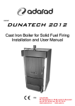
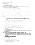
4
Fan ON/OFF switch
(optional)
USER INSTRUCTIONS
Control panel: The sketch on the right side shows the control panel of the heater.
You can reach the control panel by unlocking the button on the plastic cover on the
front panel. During operation, this cover is recommended to be kept locked.
Piezo
ignitor
The markings on the the thermostat knob refer to the following information:
Q
Off position
İgnition and pilot flame
1....3
Minimum setting of gas valve
4....6
intermediate warming
7
Maximum warming
The working range of thermostat is from 13 to 38˚C room temperature.
temperature The adjustment of
thermostat knob refers approximately to the following room temperatures;
Knob setting
Room temp. ( ˚C)
1...2
13...17
3
21
4
25
5
30
6
34
7
38
Gas Fired
Gas Fired
Balanced Flue Heater
Thermostat knob
Turning the appliance ON: Starting from OFF (z) position, turn the knob to the pilot position ( ). Push the knob
and ignite the pilot flame keeping the knob pressed for several seconds. Release the knob after kept pressed for
10 seconds, check that the pilot flame remains alight. If it goes out repeat the ignition operation.
Room temperature setting: Turn "thermostat knob" to set the main burner gas flow
Stand-by: To keep the main burner of the stove closed and the pilot flame alight, turn the knob from the selected
temperature position to the pilot position (
).
Shut off the appliance: Turn the knob to OFF position. For seasonal shutdowns, it is recommended to cut the gas
supply to the appliance.
Switching fan on/off (OPTIONAL): If your heater has an integrated convection fan, you can either switch it on or off,
according to your desire. Convection fan speeds the warming time up when in use, increasing the efficiency of the
heater at around 1 - 2%.
When the thermocouple (thermoelectric safety device) has cooled sufficiently, pilot ligthing procedure may be repeated. After the appliance has been completely shut-off, re-ignition is possible after about 1 minute (to allow the thermocouple to cool). If thermoelectric safety device actuating the flame is extinguished either intentionally or unintentionally,
no attemp should be made to relight the gas until at least 3 minutes have elapsed for safety reasons. If the appliance
goes off by any cause, or stopped by turning main gate valve or governer off, first set the thermostat knob to OFF
position, and wait for 5 minutes prior to re-start.
Models
AC2 / AC2 F
AC3 / AC3 F
AC3 / AC3 F
AC4 / AC4 F
AC5 / AC5 F
Conversion
C
i tto diff
different
t gases: Your
Y
appliance
li
iis adjusted
dj t d att th
the ffactory
t
ffor th
the llocall di
distributed
t ib t d natural
t l gas att
your location. If needed, the exchange from natural gas to LPG can only be carried out by registered service agent
or authorised people from your local dealer. Never interfere the setting of the appliance on your own.
Manufacturer's declaration of conformity
We, "Adarad Dokum Urunleri Sanayi ve Ticaret AS" located at "Organize Sanayi Bolgesi 16400 Inegol, Bursa, Turkey
(TR)", declare under our sole responsibility that the "Gas-fired independent balanced flue space heater" models,
Adarad AC2 / AC3 / AC4 / AC5 / AC2 F / AC3 F / AC4 F / AC5 F
to which this declaration relates is in conformity with the following standard(s) and normative document(s):
Council Directive 90/396/EEC on the approximation of the laws of the Member States relating to appliances burning n
gaseous fuels
Harmonized normative EN 613:2000 on Independent gas-fired convection heaterso
We declare that we have taken all necessary measures to ensure that the manufacturing process including final product
inspection and testing, results in homogeneity of production and conformity of the appliance with the type as described in
the EC-type examination cerfticate and with the requirements of above Directive with the type as described in the EC-type
examination cerfticate and with the requirements of above Directive
Adarad Dokum Urunleri Sanayi ve Ticaret AS
Rev.November.2010
Maintenance and cleaning: Your heater has no user-servicible parts. At the beginning of each heating season we
would recommend to call for a service agent and request the following controls:
1. Check of adequate gas supply from the net, gas and combustion circuit soundness, flue outlet terminal
2. Replacement of any material damaged
If needed you can clean the outer jacket of the convector with a piece of smooth cloth. Never use sharp materials and
cleaning solvents to clean the appliance.
Installation
and
User Manual
Distribuitor: CALOR SRL
Str. Progresului nr. 30-40, sector 5, Bucuresti
tel: 021.411.44.44, fax: 021.411.36.14
www.calorserv.ro - www.calor.ro
3
2
Thank you for purchasing Adarad convector. Please read this manual carefully before installation and operation of your
appliance, and keep it during the whole operation life. Do not touch or interfere any part of the appliance other than those
allowed. The installation and service of this heater requires authorised and skilled staff. For the installation of the heater and
proper room selection, this manual and mandatory regulations must be considered.
Adarad AC convector is a gas fired balanced flue room heater for independent use. The heater must always be used
with supplied telescopic flue kit in accordance with the instructions given in this manual. As it does not use the air of
your living room for the combustion, a safe operation is ensured. Thanks to its cast iron design your heater will perform
a very long operation life with a silent combustion and high efficiency. Some models are equipped with a convection
fan which helps warm faster. Convection fan is either switched on or off using the fan button on the control panel.
Adarad AC convector has an integrated multifunctional gas valve which modulates the gas flow according to desired
room temperature between 13 and 38 oC. The desired room tempearure is set by a thermostat knob on the control
panel. When desired room temperature is reached the main burner flame goes off, but pilot flame stands alight.
No external power supply is needed to control of pilot flame, main flame, and thermoelectric safety features.
INSTALLATION INSTRUCTIONS
Room arrangement: Refer to the followings to find the proper place for heater installation:
1. The hermetic flue kit of the heater must be installed through a wall next to outside where there is enough air circulation
for combustion. The flue terminal can not be routed to balconies, ventillation or lighting clearances, other rooms
2. If the heater is to be installed onto a combustible material (such as wall paper), his material should be insulated from
the appliance. Following clearances around heater must be ensured if surroundings are of combustible material:
Minimum distance from heater to side walls and upper items :
30 cm.
Minimum distance from heater to the floor:
7 cm.
3. Curtains should not be kept closer than the minimum clearances specified above to the heater.
4. Heater should not be positioned just between two side walls preventing warm air circulation around the heater
Installation: Follow the procedure step by step:
1. Drill a hole whose diameter not smaller than 150 cm
for balanced flue kit. To fix the heater, drill four holes
regarding the references on the sketch on the right.
Fit the plastic anchors supplied in the heater pack
into these four holes.
2. Flue kit is of telescopic design, and you can adjust
the total length of the flue in respect with thickness of
the wall where the heater is insalled.
3. Fix pos. 2 of flue kit on corresponding holes on the
heater air inlet chamber via pos. 5 self tapping screws
supplied in the heater pack. After this attachment, ensure
that, flue outlet ring (dia. 80 mm) on the heater firmly and
squarely fits into the internal pipe of the flue kit to prevent burnt gas leakage to fresh air side. If you do not manage,
bad emissions during combustion will rise from the flue terminal to outside.
4. Fit the heater onto wall, fixing it via four pieces of anchor screws supplied in the heater pack, driving the attached
flue kit through the hole on the wall.
5. Fix the flue terminal (pos.4) onto the other en of the external pipe of flue kit via three self tapping screws supplied
in the flue kit pack, in such a way that, when you finish the installation, the flue terminal (pos.4) should be levelled off
with the outside wall surface. You can adjust the total length of flue kit respectiveliy during this stage as well.
6. When you finish the installation you should have the same view of the system as seen in the sketch on the right hand
side below. The space between the flue terminal (pos.4) and outside wall surface must be selaed with silicon sealant
The clearance between flue kit (dia. 150 mm) and the circular hole for flue kit that you drilled on the wall must be sealed
with silikon sealant, plaster, or cement.
Delivery term
Your heater is delivered in 2 packages
1. Heater pack which holds the Adarad convector, this manual, and wall fixing elements
2. Balanced flue kit pack
Safety warnings
* Before installation, ensure that the local distribution conditions (identification of the type of gas and pressure) and the
and the adjustment of the appliance are compatible.
* Working surfaces of the convector are shown in the sketch on the right
side. As these surfaces become too hot during operation, they must
not be touched by hand.
* Do not use the appliance if the flame inspection glass is damaged.
* Do not use the convector without having the flue kit properly installed
or if there is leakage on the flue system.
* If balanced flue terminal outside neighbors a window, please keep this
window closed any time your heater is in operation.
* If you feel gas leakage, first turn the main gas valve in front of the heater
off. Do not switch any light and electrical appliance on or off. Allow more
fresh air circulation in the room, call for service agent or local gas company.
y source other than installed pilot
p
* Your heater should not be fired with any
ignition system.
* The terminal of the flue will reach excessive temperatures and then not
be touched. For this reason the flue outlet should not bepositioned to the
walls in reach of people, or should be protected.
)
)
If flue terminal is not arranged properly, the performance of the heater may be affected in strong wind and rain
Electrical installation (only for versions with convection fan): The versions supplied with convection fan
should be connected to the mains with supplied original plug. Please be sure that the supply you use for the heater
matches with the electrical properties of the appliance. This appliance must be earthed. Check before starting the
heater if there is proper earthing on the mains.
pp y The design
g and installation of g
pp
y authorized staff
Gas supply:
gas circuit to the appliance
should be carried out by
licenced by local gas authority and in accordance with mandatory regulations. The local gas supply company should
always be contacted at the design stage to ensure an adequate supply is available. Do not let unathorised people to
interfere the existing gas supply setup in case of operation or gas pressure problems. First consult your dealer or its
contracted service agent. If no problem on the appliance is found, refer to local gas supply authority.