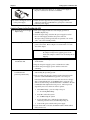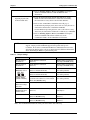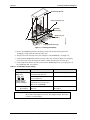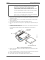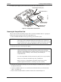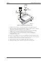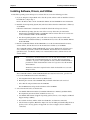
1
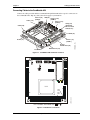
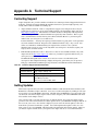
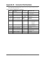
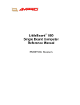
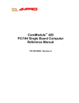
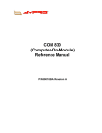
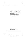
CoreModule 420 PC/104 Single Board Computer QuickStart Guide P/N 5001693A Revision A Notice Page NOTICE No part of this document may be reproduced, transmitted, transcribed, stored in a retrieval system, or translated into any language or computer language, in any form or by any means, electronic, mechanical, magnetic, optical, chemical, manual, or otherwise, without the prior written permission of Ampro Computers, Incorporated. DISCLAIMER Ampro Computers, Incorporated makes no representations or warranties with respect to the contents of this manual or of the associated Ampro products, and specifically disclaims any implied warranties of merchantability or fitness for any particular purpose. Ampro shall under no circumstances be liable for incidental or consequential damages or related expenses resulting from the use of this product, even if it has been notified of the possibility of such damages. Ampro reserves the right to revise this publication from time to time without obligation to notify any person of such revisions. If errors are found, please contact Ampro at the address listed below on the Notice page of this document. TRADEMARKS The Ampro logo is a registered trademark, and CoreModule, EnCore, Little Board, LittleBoard, MiniModule, and ReadyBoard are trademarks of Ampro Computers, Inc. All other marks are the property of their respective companies. REVISION HISTORY Revision Reason for Change Date A Initial Release Mar/04 Ampro Computers, Incorporated 5215 Hellyer Avenue San Jose, CA 95138-1007 Tel. 408 360-0200 Fax 408 360-0222 www.ampro.com © Copyright 2004, Ampro Computers, Incorporated Audience Assumptions This users guide is for the person who is setting up the CoreModule 420 to implement your design of computer related equipment, including but not limited to hardware and software design and implementation of the same. Ampro Computers, Inc. assumes you are qualified in designing and implementing your hardware designs and its related software into your prototype computer equipment. ii QuickStart Guide CoreModule 420 Contents Chapter 1 Setting Up the CoreModule 420 ....................................................................................1 Using this Guide .................................................................................................................................1 Requirements .................................................................................................................................1 What’s in the Box ...........................................................................................................................1 Setup Steps ........................................................................................................................................2 Preparations ...................................................................................................................................2 Setting Up the Workspace..............................................................................................................2 Connecting Cables to the CoreModule 420 ...................................................................................3 Connecting Boot Devices and Peripherals.....................................................................................7 Applying Power to the CoreModule 420.........................................................................................8 Chapter 2 Installing CoreModule 420 Options............................................................................11 DiskOnChip (DOC) Installation.........................................................................................................11 Tools Required .............................................................................................................................11 Installing the DiskOnChip (DOC)..................................................................................................11 Removing the DiskOnChip (DOC)................................................................................................13 CompactFlash Card Installation .......................................................................................................14 Tools Required .............................................................................................................................14 CompactFlash Card Installation Guidelines .................................................................................14 Installing the CompactFlash Card ................................................................................................14 Removing the CompactFlash Card ..............................................................................................16 Installing Software, Drivers, and Utilities ..........................................................................................18 Appendix A Technical Support ........................................................................................................21 Contacting Support ...........................................................................................................................21 Getting Updates................................................................................................................................21 Appendix B Connector Part Numbers.............................................................................................23 List of Figures Figure 1-1. Figure 1-2. Figure 1-3. Figure 1-4. Figure 1-5. Figure 1-6. Figure 2-1. Figure 2-2. Figure 2-3. Figure 2-4. Figure 2-5. CoreModule 420 Connector Locations ...........................................................................3 Module Pin-1 Locations...................................................................................................3 Connecting IDE, Video, and Floppy/Parallel Cables ......................................................4 Connecting Floppy-to-Parallel Adapter Cable.................................................................5 Connecting Utility, Serial(s), Ethernet, USB, and Power Cables ....................................6 Connecting Battery..........................................................................................................6 Installing DiskOnChip....................................................................................................12 Removing DiskOnChip..................................................................................................13 Installing the CompactFlash Card.................................................................................15 CompactFlash Card Installed........................................................................................16 Removing the CompactFlash Card...............................................................................17 List of Tables Table 1-1. Table 2-1. Table A-1. Table B-1. Jumper Settings .............................................................................................................10 DiskOnChip Jumper Settings .........................................................................................12 Technical Support Contact Information .........................................................................21 Connector and Manufacturer’s Part Numbers ...............................................................23 CoreModule 420 QuickStart Guide iii Contents iv QuickStart Guide CoreModule 420 Chapter 1 Setting Up the CoreModule 420 Using this Guide This guide provides the most efficient way to set up your CoreModule 420 single board computer (SBC). The instructions provided in this guide include: • Removing the CoreModule 420 from the shipping container and inventorying the accessories • Connecting cables to the CoreModule 420 • Connecting the peripherals, boot devices, and power supply to the CoreModule 420 • Powering up the CoreModule 420 Information not provided in this QuickStart Guide includes: • CoreModule 420 SBC Specifications • Environmental requirements • CoreModule 420 connector/pin numbers and definitions • Supplied software use and programming considerations Requirements The following peripherals and devices are needed to make full use of the CoreModule 420. • Peripherals (Customer provided): ♦ Keyboard (PS/2 Adapter provided in QuickStart Kit) ♦ PS/2 Mouse ♦ CRT Monitor • Power Supply (Customer provided): ♦ AT or +5V power supply – Typically, an AT power supply is required to provide power to the CoreModule 420 SBC and its associated peripherals and boot devices. • Boot Devices (one or more - Customer provided): ♦ Floppy Disk drive (adapter cable provided by Ampro) ♦ CD-ROM ♦ IDE hard disk drive ♦ DiskOnChip ♦ CompactFlash card (may be provided by Ampro) • Optional Devices/Connections (Customer provided): ♦ TFT Flat Panel and custom cable ♦ Ethernet connection ♦ USB Devices What’s in the Box Refer to the QuickStart Kit Contents Sheet for a list of the items in the shipping container. CoreModule 420 QuickStart Guide 1 Chapter 1 Setting Up the CoreModule 420 Setup Steps It is important to follow the setup steps in this section in the exact order listed here, but skip any steps that do not apply to your situation. References are provided to chapters within this guide or other Ampro documents for more information about installation and use of the CoreModule 420 SBC. Preparations • Locate the QuickStart Kit Contents Sheet 1) Open shipping box • Unpack the contents of the shipping box • Verify the contents of the shipping box against the QuickStart Contents Sheet included with your CoreModule 420 SBC shipping box. 2) Verify Contents • If anything is missing or damaged, call your sales representative or Tech Support. 3) Support Documentation (CoreModule 420 Documentation and Support Software (Doc & SW) CD-ROM) CoreModule 420 QuickStart Guide This hardcopy document describes how to setup, install, and power up the CoreModule 420 found in the QuickStart Kit and this manual is also provided as a PDF file on the CoreModule 420 Documentation and Support Software (Doc & SW) CD-ROM. CoreModule 420 Reference Manual This document describes the CoreModule 420 and provides detailed reference information for your CoreModule 420 and is found on the CoreModule 420 Doc & SW CD-ROM as a PDF file. Setting Up the Workspace CAUTION To prevent damage to the electronic components on the CoreModule 420 SBC, do not handle the board until you have followed good Electro-Static Precautions. Always touch a grounded, unpainted metal surface before touching the CoreModule 420 SBC or any of the components on the board. Always use an anti-static wrist strap connected to a grounding mat, which has staticdissipating characteristics and attached to earth ground. 4) Select workbench location • The workbench location should have a static-free, non-conductive mat (or the equivalent) to place the CoreModule 420 and its cables for setup and operation (including the connection of the power supply, peripherals, and support devices). 5) Connect an ESD strap to your body • Connect an ESD strap between your body (wrist or ankle) and ground or the static-free mat. 6) Unpack CoreModule 420 2 If you do not have your own ESD strap, an ESD kit is provided in the QuickStart Kit with an anti-static wrist strap. • Remove the CoreModule 420 from its protective plastic case and place it on static-free work surface. QuickStart Guide CoreModule 420 Chapter 1 Setting Up the EnCore 420 Connecting Cables to the CoreModule 420 Connect the cables provided with the CoreModule 420 QuickStart Kit to the respective connectors on the CoreModule 420. Skip any cable(s) that do not apply to your situation. IDE (J6) Serial 2 (J9) (COM 2) Serial 4 (J14) (COM 4) Serial 3 (J13) (COM 3) Video (J11) Utility (J5) (Keyboard, Mouse, Reset Switch, etc.) USB (J10) GPIO (J8) Power (J7) CM420QkS_03a Serial 1 (J3) (COM 1) Floppy/ Parallel Port (J4) Ethernet Port (J2) PC/104 Bus Figure 1-1. CoreModule 420 Connector Locations JP1 J5 JP6 J6 J3 9 10 10 J9 J14 J13 4 2 3 1 JP5 JP4 J4 JP8 JP9 JP7 1 J8 2 J11 U5 D1 D2 U14 J10 JP2 J7 Pin 1 locations are marked with , , or . CM420QkS_01e J2 P1B P1A P1C P1D Figure 1-2. Module Pin-1 Locations CoreModule 420 QuickStart Guide 3 Chapter 1 Setting Up the CoreModule 420 Skip any steps that do not apply to your situation. 1) Connect IDE cable The IDE cable and its adapter are connected to the IDE connector (J6). See Figures 1-1, 1-2, and 1-3. 2) Connect Floppy/Parallel cable The floppy/parallel cable is connected to the Floppy/Parallel port (J4). See Figures 1-1, 1-2, and 1-3. 3) Connect Floppy-to-Parallel adapter cable The Floppy-to-Parallel adapter cable is connected to the cable connected to the Floppy/Parallel port (J4). See Figures 1-3, and 1-4. NOTE 4) Connect Video cable (CRT) Video Connector The Floppy-to-Parallel adapter cable is only required when using the floppy disk drive to access floppy diskettes. To use the parallel port for printer output, disconnect the Floppy-to-Parallel adapter cable and connect directly to the printer’s cable. The video cable (CRT) is connected to the Video connector (J11). See Figures 1-1, 1-2, and 1-3. IDE Connector Pin Adapter (2mm to .1 inch) (Shown with only one connector for simplicity) Pin 1 CM420QkS_08a Floppy/Parallel Port Connector Figure 1-3. Connecting IDE, Video, and Floppy/Parallel Cables 4 QuickStart Guide CoreModule 420 Chapter 1 Setting Up the EnCore 420 Floppy B Utility (J5) Serial 1 (J3) Floppy A (Typical) Floppy/Parallel Cable to (J4) Floppy-to-Parallel Adapter Cable CM420QKS_11a Floppy/Parallel (J4) Figure 1-4. Connecting Floppy-to-Parallel Adapter Cable 5) Connect Utility cable The Utility cable is connected to the Utility connector (J5). See Figures 1-1, 1-2, and 1-5. 6) Connect Serial cables The serial cables are connected to the respective Serial ports (J3, J9, J13, and J14). See Figures 1-1, 1-2, and 1-5. All four serial ports use the same type cable for each port (vertical or right angel). 7) Connect Ethernet cable The Ethernet cable is connected to the Ethernet connector (J2). See Figures 1-1, 1-2, and 1-5. 8) Connect USB cable The USB cable is connected to the USB connector (J10). See Figures 1-1, 1-2, and 1-5. 9) Connect RTC Battery The RTC battery and its cable are connected to the Utility cable connector to power the RTC. See Figures 1-5 and 1-6. CoreModule 420 QuickStart Guide 5 Chapter 1 Setting Up the CoreModule 420 10) Connect Power cable The Power cable is connected to the power connector (J7). See Figures 1-1, 1-2, and 1-5. NOTE (Full cables for Serial Ports 3 & 4 are not shown for simplicity) The connector on the free end of the cable is the same type connector provided on AT or ATX power supplies used to connect to hard disk drives. Keyboard Connector Mouse Connector Speaker Reset Switch Power LED Serial 2 (COM 2) Cable USB Cable RTC Battery Connector Utility Cable Ethernet Cable Power Cable (Standard power connector for Hard Disk Drives found on AT or ATX Power Supplies) CM420QkS_09a Serial 1 (COM 1) Cable Connecting Battery CM420QkS_10a Figure 1-5. Connecting Utility, Serial(s), Ethernet, USB, and Power Cables Figure 1-6. Connecting Battery 6 QuickStart Guide CoreModule 420 Chapter 1 Setting Up the EnCore 420 Connecting Boot Devices and Peripherals 11) Connect the OS boot devices • There are four options for connecting an (OS) boot device to the CoreModule 420: Skip the devices that are not applicable to your situation. a) Connect a floppy disk drive to the floppy/parallel cable connected to J4 on the CoreModule 420. b) Connect an IDE hard disk drive to one of the free connectors on the IDE cable. Use one of the free IDE pin adapter PCBs to connect the IDE hard disk drive. The IDE cable has two connectors with 2mm-to-0.1” adapters on each one for connection to an IDE hard disk drive and CD-ROM. NOTE Ampro does not recommend using a hard drive with a preinstalled OS from another model PC, to boot the CoreModule 420. This has proven to cause problems or provide unreliable operation. Use a bootable device (floppy, CD-ROM, or CF) to load the OS onto the hard drive while attached to the CoreModule 420. Additional drivers can be loaded while still connected to the CoreModule 420. Refer to Step 21. c) Connect a CD-ROM drive to the available connector on IDE cable from J6 on the CoreModule. Use the second or free IDE pin adapter PCB & 2mm connector on the IDE cable to connect the CD-ROM drive. d) Install a CompactFlash card with a bootable OS into the CompactFlash socket (J12). Instructions and limitations for installing the CompactFlash card into the socket (J12) on the CoreModue 420 are provided in Chapter 2, Installing CoreModule 420 Options later in this manual. CompactFlash Card 12) Connect the device cables to the CoreModule cables This includes the keyboard, mouse, CRT monitor, power supply, and any remaining devices you want connected during the boot process. • Connect the keyboard to the larger (DIN) connector on the Utility cable. If required, a PS/2-to-AT adapter is provided in QuickStart Kit. • Connect the mouse to the PS/2 connector on the Utility cable. • Connect the CRT monitor cable to the Video connector from J11 on the CoreModule. CoreModule 420 QuickStart Guide 7 Chapter 1 Setting Up the CoreModule 420 • Connect the AT power supply (or +5 voltage power supply) to the power connector on J7 of the CoreModule. 13) Connect all support devices to the power supply • Ensure all of the support devices you have plugged into the connectors from the CoreModule have good power connections to the AT power supply. Applying Power to the CoreModule 420 14) Check/Set the Power Supply Input Voltage • If the power supply module uses auto-ranging operation at 50/60Hz, skip this step. • Check the input voltage switch on the power supply located on the rear of the supply just below the power connector. 15) Check jumpers on the board The input voltage switch typically has two positions: 115 or 230 volts – 115 volts is default position. • Check the jumpers on the CoreModule 420 before applying power to the board. Refer to Figure 1-2 and the Table 1-1 at the end of this chapter. CAUTION 16) Power up the CoreModule 420. To prevent damage to the CoreModule 420, check the jumper settings before applying power to the board. The jumpers could be loose or missing due to shipping. • Plug the CRT monitor’s power cord into an AC outlet and turn on the monitor. • Plug the AT power supply’s power cord into the AC outlet. • Turn the AT power supply’s power switch to On before continuing. 17) Verify the CoreModule 420 powers-up satisfactorily. • You should see POST complete successfully before the system starts loading the operating system. • If the operating system (OS) is found, exit the OS and reboot the system to set the initial BIOS Setup options. Go to Step 16. If the desired OS is not loaded on one of the boot devices (floppy drive, CompactFlash (CF), or CD-ROM) prior to power up, you will see an error message “No Bootable Device Available” after the CoreModule 420 completes the boot process. The boot process stops until you to select from one of these options: ♦ Enter BIOS Setup – press S or skip to Step 18. S – for entering BIOS Setup ♦ Press R to reboot the system. R – for Rebooting the system ♦ Load a bootable device with the Operating System included, press R to reboot, and then skip to Step 18. ♦ Turn off the power switch on the power supply. • If you do not make a selection, the POST routine remains stalled, until you intervene. 8 QuickStart Guide CoreModule 420 Chapter 1 Setting Up the EnCore 420 18) Enter BIOS Setup Utility • Press the <Del> key during POST, or S to enter BIOS Setup. • Use BIOS Setup during the initial boot to set the desired options (time and date, alter the boot drive for the floppy drive, CDROM, or hard disk drive, etc.). • Refer to the next step to alter the boot sequence, while in Setup. 19) Alter Boot Order, only if needed. • If you need to alter the boot sequence to select a bootable device, perform the items listed in this step. a) Select the BIOS and Hardware Settings menu as shown in the figure to the right and press Enter. Ampro Setup Util > BIOS and Hardware Settings Reload Initial Settings Load Factory Default Settings Exit, Saving Changes Exit, Discarding Changes b) Select the first drive in the Boot Order as highlighted to the right. NOTE The CD-ROM or CompactFlash (CF) must be listed in Drive Assignment and the Boot Order to be recognized by the BIOS. CF can only be listed as C or D drive in the Boot Order. Ampro Setup Utility for CoreMod [Drive Assignment] Drive A 1.44 MB, 3.5” Drive B (none) Drive C HDD on Pri Master Drive D CDROM on Pri Slave Drive E (none) [Boot Order] > Boot 1st Drive A: < Boot 2nd Drive C: CDROM Boot 3rd Boot 4th (none) Boot 5th (none) Boot 6th (none) [Drive and Boot Options] bootseq03a This example assumes Drive A is a 3 ½” floppy drive, Drive C is an IDE HDD, and the 3rd drive is an IDE CD-ROM. < enterBIOS02a The sub-steps listed here show you how to change the Boot Sequence while in the BIOS Setup Utility. c) Move the CD-ROM up in the Boot Order. • Use the Arrow keys and PU/PD keys to move the CD-ROM up in the Boot Order. d) Exit and Save changes. • If you want to keep the floppy drive and hard drive in the boot order, you will need to make changes to the other Boot Order devices. 20) If using a CompactFlash For example, change Boot 3rd to Drive A, to keep it in the boot sequence. • If you did not receive a CompactFlash card from Ampro, go to the next step, Step 21. • If you received a CompactFlash card from Ampro with your system, use the compact flash card to boot the system. • If you have to change the boot order to do so, refer to Step 19. • If you do not intend to install the OS or additional drivers onto the hard disk drive, skip Step 21. See jumper setting next page. CoreModule 420 QuickStart Guide 9 Chapter 1 Setting Up the CoreModule 420 • Refer to Installing Software, Drivers, and Utilities in Chapter 2 and the CoreModule 420 Doc & SW CD-ROM for more information. 21) Install the desired Operating System (OS) on the hard disk drive. • Locate the desired Operating System (OS) diskette(s), or CDROM and follow the manufacturer’s instructions for installing the OS and the necessary drivers onto the hard disk drive. • Refer to Note on Hard Drive installation from 11b, page 7. For Windows Operating Systems, most of the necessary drivers are found on the manufacturer’s installation CD-ROM. For non-Windows Operating Systems, some or all of the necessary drivers may be found on the manufacturer’s diskette(s) or CD-ROM. • Refer to Installing Software, Drivers, and Utilities in Chapter 2 and the CoreModule 420 software subdirectory on the CoreModule 420 Doc & SW CD-ROM for instructions. NOTE The CoreModule 420 SBC ships from the factory configured only for CRT support. Ampro provides LCD/TFT support for flat panels with specific resolutions. Refer to the CoreModule 420 Reference Manual, the Release Notes, and Virtual Technician on the web site for instructions and additional information when customizing the BIOS to a particular flat panel. Table 1-1. Jumper Settings Jumper # Installed Removed JP1 Serial Port 1 Termination Enable RS485 Termination (Pins 1-2) Disable RS485 Termination (No jumper) Default setting JP2 Serial Port 2 Termination Enable RS485 Termination (Pins 1-2) Disable RS485 Termination (No jumper) Default setting JP4 & JP5 BIOS/DOC Select JP5 JP4 Enable Internal BIOS – Normal operation, (Pins 1-3 on both JP4 & JP5) Disabled – Won’t Boot (See other positions) Enable External BIOS – Used for recovery (Pins 1-2 on both JP4 & JP5) Disabled – Won’t Boot (See other positions) BIOS/DOC Select Jumper Setting (Shown in Default) Enable DOC – Boot from DiskOnChip in bytewide socket (Pins 1-3 & 2-4 on both JP4 & JP5) Default setting Disabled – Won’t Boot (See other positions) JP6 Flat Panel Voltage Selection +3.3 Volts (Pins 1-2) +5 Volts (Pins 2-3) JP7 DiskOnChip Boot Address Select Access from DC000h-DDFFFh (Pins 1-2) Access from CC000h-CDFFFh (No jumper) JP8 Serial Port 1 Enable Serial Port 1 (Pins 1-2) Default setting Disabled Serial Port 1 (Pins 2-3) JP9 Serial Port 2 Enable Serial Port 2 (Pins 1-2) Default setting Disabled Serial Port 2 (Pins 2-3) 4 3 24 1 2 1 Note: JP8 and JP9 Enable/Disable the Serial ports at the STPC Altas CPU chip. 10 QuickStart Guide CoreModule 420 Chapter 2 Installing CoreModule 420 Options The procedures in this chapter describe how to install or remove the supported options onto the CoreModule 420 single board computer (SBC). Some of the CoreModule 420 options described in this chapter may require turning the CoreModule 420 over to install or remove the option from the CoreModule 420. DiskOnChip (DOC) Installation The CoreModule 420 SBC supports the DiskOnChip by M-Systems in the bytewide socket (U5). NOTE The DiskOnChip is not listed as a drive and is not in the boot order. Refer to the software instructions provided with the specific DiskOnChip device for more information concerning booting the device. Tools Required Use a complete anti-static service kit (or the equivalent) to remove or install the DiskOnChip onto the CoreModule 420. A complete anti-static service kit should include a static-dissipating work surface, a chassis clip lead, and a wrist or ankle strap. Installing the DiskOnChip (DOC) CAUTION To prevent damage to the CoreModule 420 or the DiskOnChip, ensure the power supply to the CoreModule 420 is turned off and the power cord has been removed from the power source. Most AT power supplies will continue to provide standby current to the CoreModule 420 until the power cord is disconnected. 1. If the CoreModule 420 SBC is already powered up, power down the system and remove the power cord from the power supply. CAUTION To prevent damage to the static sensitive components on the CoreModule 420, ensure you follow good Electrostatic Discharge principles. The CoreModule 420 and the DiskOnChip are sensitive to static electricity and can be easily damaged by improper handling. Do the following when handling the CoreModule 420 and its related DiskOnChip: Always use an anti-static wrist/ankle strap and a grounding mat. Before you handle the CoreModule 420 or remove the DiskOnChip from the antistatic bag, touch a grounded, unpainted metal surface to discharge any static electricity. 2. Verify the bytewide socket (U5) pins are clear of any material or obstructions that would prevent installation or bend the DiskOnChip pins. CoreModule 420 QuickStart Guide 11 Chapter 2 Installing CoreModule 420 Options DiskOnChip Module Utility Connector (J5) Bytewide Socket (U5) Pin 1 Floppy/Parallel Port (J4) CM420QkS_04a Serial Port (J3) (COM 1) Figure 2-1. Installing DiskOnChip 3. Remove the DiskOnChip from the anti-static package and check it for bent pins, before attempting to insert it into the bytewide socket (U5). 4. Align pin one of the bytewide socket (U5) with pin 1 of the DiskOnChip. See Figure 2-1. 5. Gently insert the DiskOnChip into the bytewide socket (U5) as shown in Figure 2-1 and gently rock it side to side, while pressing down, until it is firmly into the bytewide socket (U5). 6. Set the jumpers for JP4, JP5, and JP7 to boot from the DiskOnChip before you restore power to the CoreModule 420. See Table 2-1 Table 2-1. DiskOnChip Jumper Settings Jumper # Installed Removed JP4 & JP5 BIOS Select JP5 JP4 Enable BIOS – Normal operation; boots from flash (Pins 1-3) Disabled (See other positions) Enable External BIOS – Used for recovery (Pins 1-2) Disabled (See other positions) BIOS/DOC Select Jumper Setting (Shown in Default) Enable DOC – Boot from DiskOnChip in bytewide socket (Pins 1-3 & 2-4) Default Disabled (See other positions) JP7 Boot from DC000h-DDFFFh (Pins 1-2) Boot from CC000h- CDFFFh (No jumper) 4 3 NOTE 12 24 1 2 1 DiskOnChip Boot Address Refer to the CoreModule 420 Reference Manual for more information on the location of the jumpers, as well as, other jumper settings. Refer also to Table 1-1 in this manual. QuickStart Guide CoreModule 420 Chapter 2 Installing CoreModule 420 Options Removing the DiskOnChip (DOC) CAUTION To prevent damage to the CoreModule 420 or the DiskOnChip, ensure the power supply to the CoreModule 420 is turned off and the power cord has been removed from the power source. Most AT power supplies will continue to provide standby current to the CoreModule 420 until the power cord is disconnected. 1. Ensure the CoreModule 420 power supply is turned off and the power cord is removed from the power supply. CAUTION To prevent damage to the static sensitive components on the CoreModule 420, ensure you follow good Electrostatic Discharge principles. The CoreModule 420 and the DiskOnChip are sensitive to static electricity and can be easily damaged by improper handling. Do the following when handling the CoreModule 420 and its related DiskOnChip: Always use an anti-static wrist/ankle strap and a grounding mat. Before you handle the CoreModule 420 or remove the DiskOnChip from the antistatic package, touch a grounded, unpainted metal surface to discharge any static electricity. 2. Grasp the DiskOnChip and gently rock it side to side while lifting it up out of the bytewide socket. 3. Lift the DiskOnChip away from the bytewide socket and put it on an anti-static surface or antistatic package for safe keeping. See Figure 2-2. DiskOnChip Module Bytewide Socket (U5) Floppy/Parallel Port (J4) CM420QkS_04b Serial Port (J3) (COM 1) Figure 2-2. Removing DiskOnChip CoreModule 420 QuickStart Guide 13 Chapter 2 Installing CoreModule 420 Options CompactFlash Card Installation The CompactFlash interface allows you to substitute a solid-state flash memory card for a conventional hard disk drive. The socket (J12) accepts standard CompactFlash media (card), similar to a PCMCIA memory card, but smaller. The CompactFlash card is used in much the same way as a removable-media hard drive. Any DOS or Windows based application, including the operating system, utilities, drivers, and application programs, can easily be run from the CompactFlash card without modification. NOTE Use only Type I or II PC cards from commercially available suppliers, but check for compatibility with UDMA 100 IDE hard disk drives Older CompactFlash cards that are not compatible with UDMA 100 IDE hard disk drives may cause system hangs. Tools Required The following tools are needed to remove and install the CompactFlash card onto or off of the CoreModule 420 SBC. • Small to medium, flat blade screwdriver • Anti-static service kit – Use a complete anti-static service kit (or the equivalent) to remove or install the CompactFlash card. A complete anti-static service kit should include a staticdissipating work surface, a chassis clip lead, and a wrist or ankle strap. CompactFlash Card Installation Guidelines The CompactFlash card is a solid-state disk device that emulates an IDE drive. When installed, it becomes one of the two IDE drives supported by the primary EIDE disk controller. • Use commercially available CompactFlash cards with Type I or II PC card connector. • Configure the CompactFlash card in the BIOS Setup Utility as [CF on Sec Master]. Installing the CompactFlash Card This procedure describes discounting enough cables to turn the CoreModule 420 over, exposing the bottom of the board to install or remove the CompactFlash card. 1. CoreModule 420 preparation: ♦ If the CoreModule 420 is already prepared for CompactFlash installation, with power disconnected, skip to Step 3. ♦ If the CoreModule 420 is connected and working, power down the system and continue with next step. CAUTION To prevent damage to the CoreModule 420 or the CompactFlash card, ensure the power supply to the CoreModule 420 is turned off and the power cord has been removed from the power source. Most AT power supplies will continue to provide standby current to the CoreModule 420 until the power cord is disconnected. 2. Disconnect the power cord to the power supply. 14 QuickStart Guide CoreModule 420 Chapter 2 Installing CoreModule 420 Options CAUTION To prevent damage to the CoreModule 420 or the CompactFlash card, do not touch the either one without first discharging yourself and following good Electro Static Prevention principals. The CoreModule 420 and the CompactFlash card are sensitive to static electricity and can be easily damaged by improper handling. Do the following when handling either one: Leave the CompactFlash in the anti-static bag until you are ready to install it. Always use an anti-static wrist/ankle strap and a grounding mat. Before you remove a CompactFlash from the anti-static bag, touch a grounded, unpainted metal surface to discharge any static electricity. 3. Disconnect any cables that would prevent you from turning the CoreModule 420 over exposing the bottom of the board. 4. Turn the CoreModule 420 over to access the bottom of the board and lay it on a flat anti-static surface. See Figure 2-4. 5. Check for bent pins or debris on the pins of the CompactFlash socket (J12). 6. Remove the CompactFlash card from its protective bag, handling the CompactFlash card by its edges. 7. Insert the CompactFlash card into the slots of the protective cover, parallel to the bottom of the CoreModule 420 as shown in Figure 2-3. The CompactFlash card edge and pins are keyed to install into the socket with only one orientation. CompactFlash Socket (J12) CM420QkS_05a Pin-1 Pin-1 Marker Insert CompactFlash Card Figure 2-3. Installing the CompactFlash Card 8. Push the CompactFlash card into the socket until it is firmly into the socket and mates with the pins. See Figure 2-4. 9. Turn the CoreModule 420 back over onto the bottom of the board, placing it on the work surface. 10. Reconnect any cables you disconnected earlier to turn the board over. 11. Ensure all other connections to the CoreModule 420 are still well connected. CoreModule 420 QuickStart Guide 15 Chapter 2 Installing CoreModule 420 Options 12. Plug the power supply’s power cord into the AC power source and restore power. CompactFlash Socket (J12) CM420QkS_06a CompactFlash Card Protective Cover (Do not remove) CoreModue 420 (Bottom View) Figure 2-4. CompactFlash Card Installed Removing the CompactFlash Card This procedure describes discounting enough cables to turn the CoreModule 420 over, exposing the bottom of the board to install or remove the CompactFlash card. 1. If the CoreModule 420 SBC is already powered up, power down the system. CAUTION To prevent damage to the CoreModule 420 or the CompactFlash card, ensure the power supply to the CoreModule 420 is turned off and the power cord has been removed from the power source. Most AT power supplies will continue to provide standby current to the CoreModule 420 until the power cord is disconnected. 2. Disconnect the power cord to the power supply. CAUTION To prevent damage to the CompactFlash card, do not touch the CompactFlash card without first discharging yourself and following good Electrostatic Discharge principals. CompactFlash cards are sensitive to static electricity and can be easily damaged by improper handling. Do the following when handling the CompactFlash card: Leave the CompactFlash card in the anti-static bag until you are ready to install it. Always use an anti-static wrist/ankle strap and a grounding mat. Before you remove a CompactFlash card from the anti-static bag, touch a grounded, unpainted metal surface to discharge any static electricity. 3. Disconnect any cables that would prevent you from turning the CoreModule 420 over exposing the bottom of the board. 4. Turn the CoreModule 420 over to access the bottom of the board and lay it on a flat anti-static surface. See Figure 2-4. 5. Insert a small to medium flat blade screwdriver into the slot as shown in Figure 2-5. 16 QuickStart Guide CoreModule 420 Chapter 2 Installing CoreModule 420 Options 1st Turn Clockwise 2nd Turn CounterClockwise CM420QkS_07a Figure 2-5. Removing the CompactFlash Card 6. Turn the screwdriver clockwise to loosen the CompactFlash card as shown in Figure 2-5. 7. Move the screwdriver to the other slot and turn the screwdriver counter-clockwise to completely disengage the CompactFlash card from the socket. See Figure 2-5. 8. Grasp the two sides of the CompactFlash card and gently pull it from the CompactFlash socket/protective cover and place on anti-static surface or in anti-static bag. 9. If you are installing a new or the same CompactFlash card, skip to the Installing the CompactFlash Card procedure. 10. If your are not re-installing a new or the same CompactFlash card continue with this procedure. 11. Turn the CoreModule 420 back over onto the bottom of the board, placing it on the work surface. 12. Reconnect any cables you disconnected earlier to turn the board over. 13. Ensure all other connections to the CoreModule 420 are still well connected. 14. Plug the power supply’s power cord into the AC power source and restore power. CoreModule 420 QuickStart Guide 17 Chapter 2 Installing CoreModule 420 Options Installing Software, Drivers, and Utilities To install the operating system and respective software drivers, refer to the following procedure. 1. If you are using the CompactFlash card to boot the system, and don’t wish to install the OS onto a hard disk drive, skip to Step 3. Refer to the Release Notes on the CoreModule 420 Doc & SW CD-ROM for more information. 2. Install the desired Operating System (OS) and related drivers from the manufacturer’s diskette(s) or CD-ROM. Follow the manufacturer’s instructions to install the desired OS and respective drivers. ♦ For Windows Operating Systems, some of the necessary drivers may be found on the manufacturer’s installation diskette or CD-ROM. If more software drivers are needed, refer to the CoreModule 420 Doc & SW CD-ROM. ♦ For other Operating Systems, some or all of the necessary drivers may be found on the manufacturer’s installation diskette(s) or CD-ROM. If not, refer to the CoreModule 420 Doc & SW CD-ROM. 3. Run the CoreModule 420 Doc & SW CD-ROM to access the documentation, Release Notes, various utilities, and OS drivers not on the manufacturer’s diskette(s) or CD-ROM. The CoreModule 420 Doc & SW CD-ROM will operate on any Windows PC, allowing you to view, download, or print the contents of the CD-ROM. This includes the CoreModule 420 QuickStart Guide, CoreModule 420 Reference Manual, Release Notes, software drivers and various utilities. NOTE You must have an Internet browser to view the main menu and make selections (examples: Microsoft Internet Explorer 4.x, or greater, Netscape Navigator version 4.x, or greater, or the equivalent on a PC). Software download links are provided for Adobe Acrobat Reader version 4.x or greater to view the manuals and documents. An Internet connection is required for the Adobe Acrobat link or access to the Ampro web site. The CoreModule 420 Doc & SW CD-ROM should auto-start, but if it does not, go to the root level of the CD-ROM and locate the index.htm by: a. Selecting Run from the Start menu in any Windows PC. b. Browsing the contents of the CD-ROM until you find the index.htm at the root level. c. Select this file and press OK to start the CD-ROM. The CD-ROM starts and opens the main menu of the CD-ROM. 4. Select from the directories as shown below: 18 ♦ CoreModule 420 Documentation (CoreModule 420 Reference Manual, QuickStart Guide, Development System Users Guide, and Release notes, etc.) ♦ CoreModule 420 Software (Supported operating systems, drivers, code examples, and Board Support Packages (BSPs)) ♦ Need Adobe Acrobat? (Link to Adobe Acrobat Reader; need Internet connection) ♦ Check for Latest Updates (Hot link to Ampro web site for finding and downloading the latest updates; refer to Getting Updates in Appendix A, Technical Support; also need Internet connection) QuickStart Guide CoreModule 420 Chapter 2 Installing CoreModule 420 Options There are directories and subdirectories under these topics that should provide you with the needed manuals, utilities, and tools not explained earlier. 5. Install any special OS drivers not found on the manufacturer’s diskette(s) or CD-ROM. Refer to the directories on the CoreModule 420 Doc & SW CD-ROM for instructions on installing the special drivers for the desired OS. If the desired drivers can not be found, contact Ampro through the Virtual Technician on the web site with a request for the driver(s), or use the Link to Ampro’s web site on the CoreModule 420 Doc & SW CD-ROM to get the latest updates. Refer also to the Appendix A, Technical Support for more information. 6. Install any utilities or other development tools you may need from the CoreModule 420 Doc & SW CD-ROM. Refer to the directories on the CoreModule 420 Doc & SW CD-ROM for instructions on installing and using the utilities or development tools for the desired OS. CoreModule 420 QuickStart Guide 19 Chapter 2 20 Installing CoreModule 420 Options QuickStart Guide CoreModule 420 Appendix A Technical Support Contacting Support Ampro Computers, Inc. provides a number of methods for contacting Technical Support listed below in Table A-1. Requests for support through the Virtual Technician are given the highest priority, and usually will be addressed within one working day. • Ampro Virtual Technician – This is a comprehensive support center designed to meet all your technical needs. This service is free and available 24 hours a day through the Ampro web site at http://ampro.custhelp.com. This includes a searchable database of Frequently Asked Questions, which will help you with the common information requested by most customers. This is a good source of information to look at first for your technical solutions. However, you must register online before you can log in to access this service. Personal Assistance – You may also request personal assistance by going to the "Ask a Question" area in the Virtual Technician. Requests can be submitted 24 hours a day, 7 days a week. You will receive immediate confirmation that your request has been entered. Once you have submitted your request you can go to the "My Stuff" area and log in to check status, update your request, and access other features. • Embedded Design Resource Center – This service is also free and available 24 hours a day at the Ampro web site at http://www.ampro.com. However, you must be registered online before you can log in to access this service. The Embedded Design Resource Center was created as a resource for embedded system developers to share Ampro's knowledge, insight, and expertise gained from years of experience. This page contains links to White Papers, Specifications, and additional technical information. Table A-1. Technical Support Contact Information Method Contact Information Virtual Technician http://ampro.custhelp.com Web Site http://www.ampro.com Standard Mail Ampro Computers, Incorporated 5215 Hellyer Avenue San Jose, CA 95138-1007, USA Getting Updates This feature is provided for you on the CoreModule 420 Doc & SW (Documentation & Software) CDROM and is a hot link to Ampro’s Web site. You can access the latest updates by clicking on Check for Latest Updates in your CD-ROM’s main menu. The link on the CD-ROM takes you to the Ampro web site where the search and compare engine on the web site compares your current CD-ROM to the latest files available on the Ampro web site. Once you have made a selection of desired type of updated material, the search and compare engine generates a list of the current manuals or software updates not on your CD-ROM and displays this list on the screen for you to view. Once the list is displayed you can select the desired updates or new files from the list you want to download to your PC. You can then printout the updates or files, save it to disk, or store it on a new CD-ROM. This list includes documentation and software updates. However, you must be registered online before you login in to the Ampro web site to access this information. CoreModule 420 QuickStart Guide 21 Appendix A 22 Technical Support QuickStart Guide CoreModule 420 Appendix B Connector Part Numbers These connectors are used on the CoreModule 420 and can be used to determine the mating connectors, if you want to make your own cables. Table B-1. Connector and Manufacturer’s Part Numbers Connector Pin Number/Pin Spacing/ Orientation Manufacturer Manufacturer’s PN J2 – Ethernet 8-pin, 0.1”, right angle Molex Housing = 10-11-2063 Pins = 08-55-0102 J3 – Serial 1 10-pin, 0.1”, right angle Molex 10-89-1106 J4 – Floppy/ Parallel 26-pin, 0.1”, right angle T&B Ansley or Spectra-Strip 609-2600M or 812-2622-134 J5 – Utility 10-pin, 0.1”, right angle AMP or Molex 102387-1 or 22-55-3101 J6 – IDE 44-pin, 2mm, straight TEKA HM222BT1U-191-00 J7 – Power 10-pin, 0.1”, right angle AMP or Molex Housing = 87456-5 or 22-55-2101 AMP or Molex Contact = 87523-6 or 16-02-0103 J8 – GPIO 10-pin, 2mm, straight Adam Tech or Samtec D2PH 2 10 SG .146/.118/.420 or TW-05-06-G-D-420-110 J9 – Serial 2 10-pin, 0.1”, right angle Molex 10-89-1106 J10 – USB 5-pin, 0.1”, right angle Molex 22-12-2054 J11 – Video 44-pin, 2mm, right angle Adam Tech or Astron 2PH2R44SGA AT-PH2-44-2-1-GF J13 – Serial 3 10-pin, 0.1”, straight Molex 15-91-3100 J14 – Serial 4 10-pin, 0.1”, straight Molex 15-91-3100 CoreModule 420 QuickStart Guide 23 Appendix B 24 Connector Part Numbers QuickStart Guide CoreModule 420