1
MULTITASKER®
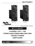
The MT101-115 is pictured above.
MANUAL PART NUMBER: 400-0402-003
MT101-114/115/117
FRONT PANELS
FOR THE 12-SLOT MULTITASKER
USER’S GUIDE
MULTITASKER
TABLE OF CONTENTS
This manual covers the following front panels for
the 12-Slot MultiTasker Enclosure:
Page
MT101-114
No Keys
Microprocessor Only
115W Power Supply
PRECAUTIONS / SAFETY WARNINGS................ 2
GENERAL..........................................................2
INSTALLATION..................................................2
CLEANING.........................................................2
FCC NOTICE .....................................................2
ABOUT YOUR MT101-114/115 .............................. 3
TECHNICAL SPECIFICATIONS.............................. 3
PRODUCT DESCRIPTION ...................................... 4
APPLICATION DIAGRAMS...................................... 5
INSTALLING YOUR MT101-114/115 ..................... 7
OPERATION ............................................................... 7
MT101-114/115 OPERATION ............................8
RS-232 CONNECTION ......................................9
RS-232 COMMUNICATION ...............................9
DESCRIPTION OF COMMANDS .....................10
RS-232 COMMANDS .......................................10
SYSTEM COMMANDS ................................10
GROUP COMMANDS..................................12
CONFIGURATION COMMANDS .................13
SPECIAL COMMANDS................................14
LED COMMANDS........................................16
KEY COMMANDS........................................17
SUBROUTINE COMMANDS .......................22
SUMMARY OF COMMANDS ...........................25
CONTROL SOFTWARE...................................26
MENU MODE ...................................................26
TROUBLESHOOTING GUIDE............................... 26
CARD IS NOT WORKING ................................26
ALTINEX POLICIES ................................................ 27
LIMITED WARRANTY/RETURN POLICIES .....27
CONTACT INFORMATION ..............................27
400-0402-003
MT101-115
36 Keys
Microprocessor
45W Power Supply
MT101-117
36 Keys
Microprocessor
115W Power Supply
1
MULTITASKER
PRECAUTIONS / SAFETY WARNINGS
•
1
Please read this manual carefully before using your
MT101-114/115/117. Keep this manual handy for
future reference. These safety instructions are to
ensure the long life of your MT101-114/115/117
and to prevent fire and shock hazards. Please read
them carefully and heed all warnings.
1.1 GENERAL
•
Qualified ALTINEX service personnel or their
authorized representatives must perform all
service.
1.2 INSTALLATION
•
To prevent fire or shock, do not expose this unit
to water or moisture. Do not place the
unit in direct sunlight, near heaters or
heat-radiating appliances, or near any liquid.
Exposure to direct sunlight, smoke, or steam can
harm internal components.
• Handle your front panel carefully. Dropping or
jarring can damage the unit. If the front panel is
not used for an extended period, disconnect the
power cord from the power outlet or turn off the
main connection.
1.3 CLEANING
•
•
Unplug the MT101-114/115/117 power cord
before cleaning.
• Clean surfaces with a dry cloth. Never use
strong detergents or solvents such as alcohol or
thinner. Do not use a wet cloth or water to clean
the unit.
1.4 FCC NOTICE
•
This device complies with Part 15 of the FCC
Rules. Operation is subject to the following two
conditions: (1) this device may not cause
harmful interference, and (2) this device must
accept any interference that may cause
undesired operation.
400-0402-003
2
This equipment has been tested and found to
comply with the limits for a Class A digital
device, pursuant to Part 15 of the FCC Rules.
These limits are designed to provide reasonable
protection against harmful interference when the
equipment is operated in a commercial
environment. This equipment generates, uses,
and can radiate radio frequency energy and if
not installed and used in accordance with
instructions found herein, may cause harmful
interference to radio communications. Operation
of this equipment in a residential area is likely to
cause harmful interference in which case the
user will be required to correct the interference
at his own expense.
Any changes or modifications to the unit not
expressly approved by ALTINEX, Inc. could void
the user’s authority to operate the equipment.
MULTITASKER
ABOUT YOUR MT101-114/115/117
2
TECHNICAL SPECIFICATIONS
3
Specifications are subject to change.
See www.altinex.com for up-to-date information.
MT101-114/115/117
Front Panels for the MultiTasker
12-Slot Enclosure
FEATURES/
DESCRIPTION
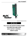
The MT101-114, MT101-115, and MT101-117 are
currently the three front panels available for the
MT100-108, 12-Slot MultiTasker. The front panel is
ordered separately based on the best solution for
the particular application.
MT101-114/115/117
GENERAL
Compatibility
Designed for use with
MultiTasker
12-Slot Enclosures
Select the MT101-115 panel for applications in
which the MultiTasker needs to be controlled from
the front panel. This panel provides 36 keys which
are user-programmable. This is accomplished by
connecting a computer to the MT101-115 through
its 9-pin D-Sub RS-232 communication port and
programming the functionality of each key using
Windows® software provided by ALTINEX. In
applications where more power is required, the
MT101-117 should be used.
Table 1. MT101-114/115/117 General
Once programmed, the keys can be used to affect
the pre-programmed switching functions and
operational
functions
such
as
press,
press-and-hold, and turning LEDs on and off. The
keys offer removable transparent faces allowing
access to removable labels for easy identification of
programmed functions. The key layout on the
MT101-115/117 resembles a typical switcher or
matrix switcher configuration with larger keys used
for input/output control and smaller keys used for
special features.
Table 2. MT101-114/115/117 Mechanical
MECHANICAL
MT101-114/115/117
T° Operating
10°C-35°C
T° Maximum
50°C
Humidity
90% non-condensing
MTBF (calc.)
ELECTRICAL
65,000 hrs
MT101-114/115/117
Power Availability MT101-114/117
Voltage
Max. Current
+6V
9.0A
-6V
2.5A
+13V
1.8A
-13V
Maximum Total Power
The MT101-114 panel can be used for applications
in which the MultiTasker will only be controlled with
a computer or third-party control system. Although
it does not offer any keys, it does have the main
microprocessor for the MultiTasker installed on the
inside of the panel which is required for external
RS-232 control of the MT100-108.
(Not the sum of max values.)
0.9A
115W
Power Availability MT101-115
Voltage
Max. Current
+6V
3.7A
-6V
1.5A
+13V
0.5A
-13V
Maximum Total Power
(Not the sum of max values.)
0.5A
45W
Table 3. MT101-114/115/117 Electrical
400-0402-003
3
MULTITASKER
PRODUCT DESCRIPTION
4
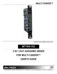
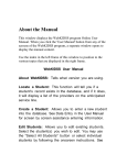
MT101-114
MT101-115/117
RS-232
RS-232
RS-232 CONTROL
FROM FRONT PANEL
RS-232 CONTROL
FROM FRONT PANEL
36 PROGRAMMABLE
BUTTONS
MT101-115/117
KEY NUMBER LOCATIONS
1
2
13
14
15
16
17
18
19
20
3
4
29
30
31
32
33
34
35
36
5
6
400-0402-003
21
4
22
23
24
25
26
27
28
7
8
9
10
11
12
MULTITASKER
APPLICATION DIAGRAMS
5
DIAGRAM 1 – INSTALLATION INSTRUCTIONS
WARNING
LARGE 8-PIN HEADER
on PCB-A and PCB-B
Disconnect the AC
power cord from
the enclosure
before making any
changes.
Connect power from the power
supply connector as shown.
Connect the
AC power
cable from the
rear panel of
the enclosure
to the power
supply.
SMALL 10-PIN HEADER
on PCB-A and PCB-B
Connect the signal cable
connector from front panel
PC board as shown.
PCB-A
PCB-B
Connect the ribbon
cable from the rear
DB9 connector on the
rear of the enclosure
to the front panel PC
board.
TO PCB-A
POWER
TO PCB-A
SIGNAL
POWER SUPPLY
FRONT PANEL PC BOARD
Connect the
signal cable
to PCB-B.
Make sure
the ribbon
cable is
on this
side as
shown.
10-PIN
HEADER
P4
Connect the 10-pin connector of the power
supply "Y" cable to the power supply.
Next, connect the two 8-pin connectors to
enclosure headers PCB-A and PCB-B as
shown.
Connect the
signal cable
to PCB-A.
Make sure the ribbon
cables are on this side of
the connector as shown.
NOTE
On some versions, P3 is
slightly under the power
supply card. The cable
can be installed without
removing the power
supply.
400-0402-003
10-PIN
HEADER
P3
10-PIN
HEADER
P1
TO PCB-B
5
TO PCB-A
MULTITASKER
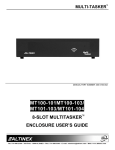
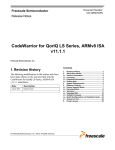
DIAGRAM 2 – SAMPLE MATRIX SETUP
SYS
PWR
ON/
OFF
KEYS 13-20
SELECT INPUTS 1-8
KEYS 21-28
SELECT OUTPUTS 1-8 for VOLUME ADJ.
KEYS 29-36
SELECT OUTPUTS 1-8
V
SUBROUTINES
{WRS1=LED*=0}
// Turn all LEDs OFF
{WRS1=LED1=1}
// Turn LED1 ON
{WRS1=WRC4C8G1}
// Assign Group 1
{WRS2=ONG1,LED2=1}
// Turn Group 1 ON
{WRS52=OFFG1,LED2=0} // Turn Group 1 OFF
{WRS13=I1&}
{WRS14=I2&}
{WRS15=I3&}
{WRS16=I4&}
{WRS17=I5&}
{WRS18=I6&}
{WRS19=I7&}
{WRS20=I8&}
// Select Input:
//
//
//
//
//
//
//
{WRS29=&O1&}
{WRS30=&O2&}
{WRS31=&O3&}
{WRS32=&O4&}
{WRS33=&O5&}
{WRS34=&O6&}
{WRS35=&O7&}
{WRS36=&O8&}
// Select Output:1
//
2
//
3
//
4
//
5
//
6
//
7
//
8
{WRS11=&C4}
{WRS12=&G1}
// Select Video Only
// Select Video+Audio
{WRS7=+}
{WRS9=-}
{WRS8=RUPC8}
{WRS10=RDNC8}
{WRS108=RSTC8}
// Increment Volume
// Decrement Volume
// Ramp Up
// Ramp Down
// Stop Ramping
{WRS21=SEL1C8}
{WRS22=SEL2C8}
{WRS23=SEL3C8}
{WRS24=SEL4C8}
{WRS25=SEL5C8}
{WRS26=SEL6C8}
{WRS27=SEL7C8}
{WRS28=SEL8C8}
// Select Output:1
// (for vol. adj.) 2
//
3
//
4
//
5
//
6
//
7
//
8
400-0402-003
{WRK1=0,0,0,1,0}
1
2
3
4
5
6
7
8
6
KEYS
// Press&Hold to clear LEDs
{WRK2=2,52,0,0,0}
// Turn Group 1 On/Off
{WRK13=13,0,0,0,0}
{WRK14=14,0,0,0,0}
{WRK15=15,0,0,0,0}
{WRK16=16,0,0,0,0}
{WRK17=17,0,0,0,0}
{WRK18=18,0,0,0,0}
{WRK19=19,0,0,0,0}
{WRK20=20,0,0,0,0}
// Select Input:
//
//
//
//
//
//
//
1
2
3
4
5
6
7
8
{WRK29=29,0,0,0,0}
{WRK30=30,0,0,0,0}
{WRK31=31,0,0,0,0}
{WRK32=32,0,0,0,0}
{WRK33=33,0,0,0,0}
{WRK34=34,0,0,0,0}
{WRK35=35,0,0,0,0}
{WRK36=36,0,0,0,0}
// Select Output:
//
//
//
//
//
//
//
1
2
3
4
5
6
7
8
{WRK11=11,0,0,0,0}
{WRK12=12,0,0,0,0}
// Select Video Card (C4)
// Select Group 1 (G1)
{WRK7=7,0,0,0,0}
{WRK9=9,0,0,0,0}
{WRK8=8,108,0,0,0}
{WRK10=10,108,0,0,0}
{SETVK8}
{SETVK10}
// + (increment)
// - (decrement)
// Ramp Up/Stop
// Ramp Down/Stop
// Key 8 = volume key
// Key 10 = volume key
{WRK21=21,0,0,0,0}
{WRK22=22,0,0,0,0}
{WRK23=23,0,0,0,0}
{WRK24=24,0,0,0,0}
{WRK25=25,0,0,0,0}
{WRK26=26,0,0,0,0}
{WRK27=27,0,0,0,0}
{WRK28=28,0,0,0,0}
// Select Output:
// (for vol. adj.)
//
//
//
//
//
//
1
2
3
4
5
6
7
8
V+A
MULTITASKER
INSTALLING YOUR MT101-114/115/117
6
OPERATION
Step 1. Turn off power to the MultiTasker
enclosure and disconnect from AC power.
The key programs and subroutines described in
this section may be programmed on-the-fly or
saved in a text file and downloaded to the
MultiTasker using communication software such as
MTSetup or AVSnap®. The sample program file
shown in DIAGRAM 2 is a simple matrix control
including volume control for an audio card. Use this
example to see how keys and subroutines are
typically programmed and organized.
WARNING! ALWAYS
DISCONNECT
THE AC POWER CORD BEFORE
OPENING THE ENCLOSURE.
Step 2. The electronic components inside the
enclosure
and
front
panel
are
static-sensitive. Please take precautions
to avoid electrostatic discharge (ESD).
7.1 TERMINOLOGY
Step 3. Remove the 6 screws on the front panel
to access the cables inside the enclosure.
Avoid handling the panel by the circuit
boards; handle by the metal panel only.
The terms below are used to increase the legibility
of the descriptions used in this section of the
manual.
Step 4. Follow
the
connector
orientation
illustrations shown in the Installation
Instructions on page 5.
CAUTION! Avoid possible electrical
damage by ensuring that all header pins
are aligned properly before restoring
power.
Step 5. After connecting the cables, fasten the
panel to the enclosure with the 6 screws
removed previously. Be careful not to
pinch any cable between the panel and
the enclosure.
Step 6. If a PC or control system is used to control
the cards in the MultiTasker, connect the
9-pin
D
connector
of
the
MT101-114/115/117 to
the
control
system’s RS-232 port.
Cn
This term refers to a MultiTasker card
where the ID number is n. Typically, “n”
is the slot number of the card, but may
also be an assigned value. Example:
C1, C2, C3, etc.
Gk
This term refers to a group of cards
where “k” is the group number. Groups
are defined using the write group
command [WR]. The possible groups
are G1-G8.
Ui
This term refers to the ID number of a
MultiTasker enclosure. The value of “i”
may be a value from 0 to 20 where 0 is
the default value in single MultiTasker
systems.
string
A string is one or more text characters
that form a command, describe output
data, or refer to incoming feedback.
MultiTasker
Computer/
Control System
GND (Ground)
Ground
feedback Feedback refers to text data that is
received from the MultiTasker or any of
the cards installed in the enclosure.
RXD (Receive)
Transmit
Sub
TXD (Transmit)
Receive
Step 7. Turn on the power switch of the
MT101-114/115/117 MultiTasker. The unit
is now operational.
400-0402-003
7
7
This term is an abbreviated form for
subroutine. A subroutine is a section of
memory used to store commands that
control the cards within the enclosure.
Example: SUB1, SUB2, etc.
MULTITASKER
7.2 MT101-114/115/117 OPERATION
MATRIX KEY CONVENTIONS
This section describes the programming and
control functions for the MT101-114, MT101-115,
and MT101-117. The MT101-114 has the same
programming capabilities as the MT101-115/117
with the exception of the key and LED functions.
The front panel is designed to use the center
group of keys for Matrix card input and output
selections.
On the MT101-115/117, the front panel uses 36
programmable keys to control plug-in cards. Each
of the 36 keys has five states. A total of 180
subroutines are available to perform different
functions based upon each key's state.
The [IDUi] and [IDU] commands can be used to
locate a specific unit on the RS-232 bus. See the
[IDUi] and [IDU] commands for details.
Key is pressed and LED is FLASHING
State 4
Key is Pressed and Held for 2.5 sec.
State 5
Key is Pressed and Held for 2.5 sec
during power-up.
= Keys 7-12
Commands used for MultiTasker cards such as
[ON], [OFF], and [IO] that end in "S" will be
saved to the memory of each card. Commands
not ending in "S" will be executed but not
restored when the system is reset or powered
off, and then on again.
Each key may be programmed to execute one
subroutine for each of the five key states. See the
{WRK} command for details.
State 3
Card Selection
SAVING CARD CONFIGURATIONS
KEY PROGRAMMING
Key is pressed and LED is ON.
= Keys 29-36
The memory is used to save key and subroutine
programs. It is non-volatile and has a storage
capacity of 64KB. The only size restriction of an
individual subroutine is that of overall available
memory.
SUB1 is always executed at power-up or on the
reset command, [RES]. Typically, SUB1 is used to
place the system cards to default settings. See the
{WRS} command for programming details.
State 2
Output Selection
MEMORY
POWER-UP SUB1 (U0/U1)
Key is pressed and LED is OFF.
= Keys 13-28
Using these conventions, the LEDs will flash
automatically showing each connection after a
completed input-to-output command has been
issued. The user should NOT issue LED
commands to these LEDs during these
sequences.
IDENTIFY UNIT ID
State 1
Input Selection
SUBROUTINES AND FUNCTION TYPES
The subroutine for a key may be programmed to
execute a complete function "I1O2C3" or a
portion of a function. As an example, matrix
functions will use one key to select the input
number, "I1", another key to select the output
number, “O2", and a final key for the group/card
ID, “C3”. See the {WRS} command for further
details.
Complete and incomplete functions mean two
different types of subroutines. Subroutines with
complete functions contain one or more
stand-alone functions which are all executed
with a single key press. Subroutines with matrix
functions require two or more keys to be
pressed to complete a single executable
function.
400-0402-003
8
MULTITASKER
7.3 RS-232 CONNECTION
7.4 RS-232 PROTOCOL
7.3.1 RS-232 COMMUNICATION
The RS-232 protocol for the MT101-114/115/117
uses a simple ASCII character format.
If a control system is used to control the cards in
the MultiTasker, connect the 9-pin D connector
of the MT101-114/115/117 to the control
system's RS-232 port. In order to connect the
MultiTasker (MT) to a computer or a terminal,
you must have the proper interface cable such
as the ALTINEX RC5201RS.
The cable must have the appropriate connector
on each end and the internal wiring must be
correct. Connectors typically have 9 pins (DB-9)
or 25 pins (DB-25).
MultiTasker
GND
TXD
RXD
DB-9
5
2
2
3
3
GND
TXD
Figure 1: DB-9 Serial Connection
MultiTasker
GND
TXD
RXD
DB-25
7
2
3
3
2
3.
Use uppercase letters for all commands.
=
=
=
=
9600
8
1
None
A command that does not request specific
information will generate feedback of “[ ]”. The
open bracket immediately followed by a closed
bracket indicates the card or unit received a
valid command. If the command requested
information from the card or enclosure, the
feedback generated is the acknowledgement of
having received a valid command. Invalid
commands generate feedback that includes
“ERR” plus an error code.
Computer
5
Brackets "{ }" are part of the command
for the panel display commands.
The enclosure and cards in a MultiTasker are
capable of performing various functions, as well
as providing feedback to the user or control
system. Commands instruct a card to perform
specific actions, request status information, and
some do both simultaneously.
RXD
9-Pin 'D' Connector
2.
Baud Rate
Data Bits
Stop Bits
Parity
Computer
5
Brackets “[ ]” are part of the command
for the controller or plug-in card.
The MT101-114/115/117 have many advanced
remote control capabilities which are accessible
through standard RS-232 communication.
Control can be accomplished using a computer,
a control system, or any other device capable of
sending RS-232 commands. The factory
settings for the RS-232 port are as follows:
Figure 1 shows the typical pinout and
connections for a DB-9 computer serial port and
Figure 2 shows the typical pinout and
connections required for a DB-25 computer
serial port.
9-Pin 'D' Connector
1.
GND
RXD
TXD
Figure 2: DB-25 Serial Connection
Example: [ERR001]
Commands ending in “S” will be saved into
memory. Commands not ending in “S” will still
be executed, but will not be restored when the
system is reset or powered-off, then on.
400-0402-003
9
MULTITASKER
7.4.1 DESCRIPTION OF COMMANDS
SYSTEM COMMANDS
Each command can consist of up to three parts:
Function, Card/Group, and Unit.
Card
commands require the card/group ID, whereas
enclosure commands do not.
System commands provide information about the
front panel, control feedback, and allow unit IDs to
be changed or identified.
1. [VER]
[ Function , Card/Group ID , Unit ID ]
This command displays the current version of
the firmware for the controller unit located in the
MT101-114/115/117.
Example: [VERC3U2]
VER
C3
U2
= Function
= Card ID or Group ID
= Unit ID (optional for Unit ID 0)
Command Format: [VERUi]
Ui = Unit ID (i = # from 0 to 20)
The card ID is a unique identifier. It is equal to
the enclosure slot number, or it may be an
assigned value. The group ID represents a
group of cards defined with the [WR] command.
All cards in a group perform the given
instruction.
Example:
NOTE: Changing the position of a card will
significantly affect control programs and
third-party control systems.
[MT101-115
690-0122-030
690-0124-027]
The unit ID may range from U0 to U20 where U0
is used for single-unit operation. If the ID is U0,
each command may be used without the unit ID.
See the command [SET] for details.
690-0122-030: Control firmware version
Query U1 for the installed firmware version.
Send the command [VERU1] to the enclosure
and the unit will return feedback similar to the
following:
MT101-115:
Front panel model number
690-0123-007: Process firmware version
690-0124-027: Panel firmware version
Example:
2. [SET]
[VERC3]:
For U0
[VERC3Ui]: For U1-U20
[VERC3]:
Equivalent to [VERC3U0]
This command sets the ID number of a front
panel and may be directed to any unit
connected to the RS-232 bus.
Command Format: [SETUxUi]
7.5 RS-232 COMMANDS
Ux = New unit ID (x = # from 0 to 20)
See the COMMAND SUMMARY (section 7.6) for a
one-line description of each command. The RS-232
available commands in this section are organized
into the following groups:
Ui = Current unit ID (i = # from 0 to 20, optional)
Example 1: ID U0
Assign U0 to a single MT101-115 by sending
the command [SETU0]. After the command is
executed, the ID will be changed to U0 and the
system will return the following feedback:
System Commands
Group Commands
Configuration Commands
Special Commands
LED Commands
Key Commands
Subroutine Commands
400-0402-003
690-0123-007
Unit ID = 0
[]
READY
10
MULTITASKER
3. [RES]
All status feedback is enclosed in brackets, “[ ].”
Each data field within the status is enclosed in
parentheses. The first two characters identify
the status type. The last three characters are the
card’s ID.
The [RES] command resets the enclosure. The
controller and all cards in the enclosure will be
reset to either their default or saved
configurations.
MT103-121
VR690-0197-005
ON
EQ10
SI1
Units with IDs U0 and U1 will beep once and
display "READY" after their initialization is
complete and all the functions stored in SUB1
have been executed. This will let the user know
that the unit is ready for operation. Units with
other IDs will beep once, but will not display any
feedback.
6. [DFB]
This command disables all feedback from one or
all MultiTasker units connected together on a
single bus; it is designed for use with 19 and 20
slot MultiTasker enclosures.
4. [?]
This command displays general information
about the MultiTasker and the cards installed.
Command Format: [?]
7. [EFB]
Example:
This command enables feedback from one
MultiTasker unit only and disables feedback
from all other units connected on the bus; it is
designed for use with 19 and 20 slot MultiTasker
enclosures.
A MultiTasker has a front panel with part
number
MT101-115
and
contains
an
MT103-121, MT103-122, and MT103-123. Send
[?] and receive the following feedback:
8. [IDUi]
[(MT101-115U0)(MT103-121C02)
(MT103-122C03)(MT103-123C04)]
MT101-115U0
MT103-121C02
MT103-122C03
MT103-123C04
This command identifies a single MultiTasker
unit within a MultiTasker system of several units.
The requested unit will flash its front panel LED
and sound its buzzer to match its ID; it is
designed for use with 19 and 20 slot MultiTasker
enclosures.
= Panel model and unit ID
= An MT103-121 is in slot 2
= An MT103-122 is in slot 3
= An MT103-123 is in slot 4
5. [?C]
9. [IDU]
This command displays general information
about a card and its status.
This command instructs each MultiTasker
connected to the RS-232 bus to flash its front
panel LED and sound its buzzer to match its ID;
it is designed for use with 19 and 20 slot
MultiTasker enclosures.
Command Format: [?Cn]
Cn = Card ID (n = # from 1 to max slots)
Example:
The MT103-121 in slot 2 is on, its equalization is
set to 10, and there is a signal detected. Send
the command [?C2] to receive the following
status:
[(MT103-121C02)(VR690-0197-005C02)
(ONC02)(EQ10C02)(SI1C02)]
400-0402-003
= Card model number
= Firmware version
= Output is enabled
= Equalization is set to 10
= Signal detect (1=yes)
11
MULTITASKER
10. [STA1]
13. [RMC]
This command enables automatic feedback
from the cards installed in the system and
affects any card with auto-feedback capability.
The default at power-on or reset is STA0 or off.
For more details, see the [?Cn] command
definitions for individual cards.
This command removes one or more cards from
a group.
Command Format [STA1]: = On
Example:
Command Format: [RMCn1Cn2…Gk]
Cn = Card ID (n= # from 1 to max slots)
Gk = Group ID (k = # from 1-8)
11. [STA0]
G5 consists of the C2, C4, C6, and C8. Remove
C6 and C8 by sending [RMC6C8G5]. View the
contents of G5 by sending [RDG5] and receiving
the following feedback:
This command disables automatic feedback
from the cards and affects any card with
auto-feedback capability.
The default at
power-on or reset is STA0 or off.
[G5=C2C4]
Command Format: [STA0]
14. [RMG]
GROUP COMMANDS
This command deletes one or all groups.
Group commands allow several cards with the
same functions to be controlled simultaneously with
a single command. Up to 8 groups (G1-G8) may be
defined.
Command Format: [RMGk]
12. [WR]
Remove all cards from G52 by sending [RMG5]:
Gk = Group ID (k = # from 1-8, * for all)
Example:
This command adds cards to a group. In
MultiTasker systems with audio and video cards,
the groups are typically as follows:
[G5=0]
Group 1 = Video Cards
Group 2 = Audio Cards
Group 3 = Video and Audio Cards
Remove all cards from all groups, effectively
deleting all groups, by sending [RMG*]. The
system will return the following feedback:
Example 2:
G1-G8: EMPTY
Command Format: [WRCn1Cn2…Gk]
15. [RD]
Cn = Card ID (n = slot # from 1 to max slots)
Gk = Group ID (k = # from 1-8)
This command reads and then displays the
members in a group.
Example:
Command Format: [RDGk]
Add C2, C4, and C6 to G5 by sending the
command [WRC2C4C6G5]. After executing this
command, G5 will consist of C2, C4, and C6.
Gk = Group ID (k = # from 1-8)
Now add C8 to G5 by sending [WRC8G5]. C8 is
added to G5, and G5 is not overwritten. View
the contents of G5 by sending [RDG5] and
receiving the following feedback:
C2, C4, and C6 make up G5. Read the member
data for G5 by sending the command [RDG5]:
Example:
[G5=C2C4C6]
The feedback shows G5 and then the cards that
make up G5. In this case, G5 includes C2, C4,
and C6.
[G5=C2C4C6C8]
400-0402-003
12
MULTITASKER
18. [RATE=S]
CONFIGURATION COMMANDS
These commands allow some basic communication
properties to be changed as well as access to
internal processor functions like BEEP and PING.
Use caution when changing RATE and BAUD
settings as changes may result in unforeseen
problems.
This command is the same as the [RATE=]
command but it also saves the communication
rate to memory. This saved rate will be restored
after power-up or reset. Only skilled
programmers should use this command.
16. [RATE]
n
Command Format: [RATE=nS]
This command displays the communication rate
between the MT101-114/115/117 and the cards
in the system. Each command that is stored in a
subroutine will be sent out to the cards at the
defined rate. Only skilled programmers should
use this command.
= rate, x100msec (n= # from 0-20)
19. [BEEPn]
This command sounds the front panel’s internal
buzzer for a specified duration.
Command Format: [BEEPn]
n
Command Format: [RATE]
= multiple of 100msec (n = # from 1-9)
Example:
Example:
Sound the buzzer for a half-second by sending
the command [BEEP5].
Check the communication rate by sending the
command [RATE] and receiving feedback
similar to the following:
20. [BEEP]
This command sounds the front panel’s internal
buzzer for a short, fixed beep.
RATE=0(0ms)
17. [RATE=]
Command Format: [BEEP]
This command sets the communication rate
between the MT101-114/115/117 and the cards
in the system. If more than one command is
stored in a subroutine, each command will be
sent out at the defined rate. Increasing the rate
effectively adds a delay between each
command stored in a subroutine. Only skilled
programmers should use this command.
Example:
Sound the buzzer for a very short beep by
sending the command [BEEP].
21. [PING]
Command Format: [RATE=n]
This command displays the “[ ]” characters and
may be used to verify communication with the
front panel.
n
Command Format: [PING]
= rate, x100msec (n= # from 0-20)
Example:
Example:
Set the communication rate to 0 by sending the
command [RATE=0] and receiving feedback
similar to the following:
Send the command [PING] and the panel will
respond with the following feedback:
[]
RATE=0(0ms)
400-0402-003
13
MULTITASKER
22. [BAUD]
In order to change the baud rate, perform the
following steps:
This command displays the current BAUD rate
setting.
1)
Press & Hold both keys 5
simultaneously for 2.5 seconds.
2)
LEDs 1, 2, 3, and 4 will turn on and one of
the four will be flashing. The flashing LED
represents the current baud rate setting.
3)
Press & Hold for 2.5 seconds the key
representing the desired baud rate.
4)
After 2.5 seconds, all 4 LEDs will be
extinguished.
5)
The new baud rate is set.
Command Format: [BAUD]
Example:
Display the BAUD rate setting by sending the
command [BAUD] and receiving feedback
similar to the following:
BAUD=9600
23. [BAUD=]
This command sets the baud rate via the
RS-232 bus. The baud rate may also be set
from the front panel keys.
These commands allow special character strings to
be sent to external devices. The strings may be
used to issue commands to custom equipment
connected to the MultiTasker. Also included in this
section are commands to test the internal memory
and display all available RS-232 commands.
= 1200, 2400, 4800, or 9600
Example 1: RS-232 BUS
Set the baud rate to 9600 by sending
[BAUD=9600]. The system will return feedback
similar to the following:
24. [TXR]
This command is used to send command strings
to the RS-232 bus through the MultiTasker.
?w3%baud=9600$#7f&changed?
Example 2: FRONT PANEL
Command Format: [TXRxyz]
Each rate is represented by one of the following
front panel keys:
Key 1 = 1200
Key 3 = 4800
xyz = text string ("abc","123",…)
Example:
Key 2 = 2400
Key 4 = 9600
1
2
1200
2400
3
4
4800
9600
5
6
Send the text string "HELLO" to the RS-232 bus.
The string will be ignored by the MultiTasker, but
not the unit receiving the command. To do this,
send the command [TXRHELLO] and the
following will be sent to the remaining devices
connected to the RS-232 bus:
13
HELLO
29
25. [TXM]
This command is used to send command strings
to the RS-232 bus through the MultiTasker, but
it adds opening and closing brackets to the
command string.
Press & Hold
Keys 5 / 6
simultaneously
for 2.5 seconds.
Command Format: [TXRxyz]
xyz = text string ("abc","123",…)
400-0402-003
6
SPECIAL COMMANDS
Command Format: [BAUD=n]
n
and
14
MULTITASKER
Example:
Example:
Send the text string "HELLO" to the RS-232 bus.
The string will be ignored by the MultiTasker, but
not the unit receiving the command.
Additionallly, it will add opening and closing
brackets. To do this, send the command
[TXMHELLO] and the following will be sent to
the RS-232 bus:
Send the command string "abc[123]xyz" to the
RS-232 bus. The string will be ignored by the
MultiTasker, but not the unit receiving the
command. Additionallly, it will remove the
opening and closing brackets. To do this, send
the command <@abc[123]xyz> and the
following will be sent to the RS-232 bus:
[HELLO]
abc[123]xyz
26. <x[y]z>
28. [TEST]
This command is used to send ISM5000
command strings to the RS-232 bus through the
MultiTasker. It transmits the “< >” symbols with
the command string and allows bracket
commands within the command string.
This command performs a non-destructive test
of the internal memory.
Command Format: <x[y]z>
In order to test the MultiTasker internal memory,
send the command [TEST]. The system will
respond as follows if the test passes:
Command Format: [TEST]
Example:
x[y]z = text string ("a[b]c" or "1[2]3" or…)
Example:
[][]
Send the command string "<abc[123]xyz>" to
the RS-232 bus. The string will be ignored by
the MultiTasker, but not the unit receiving the
command. Additionallly, it will add opening and
closing brackets. To do this, send the command
<abc[123]xyz> and the following will be sent to
the RS-232 bus:
Otherwise, failures will be indicated.
29. [HELP]
This command displays information available for
the MultiTasker interface commands or card
commands. Sending the command without a
card reference returns help for the interface.
<abc[123]xyz>
Command Format: [HELPCn], [HELPUi]
27. <@x[y]z>
Cn = Card ID (n = # from 1 to max slots)
This command is used to send ISM5000
command strings to the RS-232 bus, through
the MultiTasker. It removes the “< >” symbols in
the command string and allows bracket
commands within the command string.
Ui = Unit ID (i = # from 0 to 20)
Example 1:
In order to view the RS-232 commands
available for the MultiTasker, send the
command [HELP]. The commands along with a
brief description will be displayed in the Terminal
Window.
Command Format: <x[y]z>
x[y]z = text string ("a[b]c" or "1[2]3" or…)
Example 2:
In order to view the RS-232 commands
available for C2, send the command [HELPC2].
The commands along with a brief description will
be displayed in the Terminal Window.
400-0402-003
15
MULTITASKER
Examples:
LED COMMANDS
LED commands apply to the MT101-115/117 only
and are used to control the LED states and retrieve
matrix settings based upon key entries. The LED
states (on, off, flashing) may be controlled directly
over the RS-232 bus or through the use of
subroutines programmed into the front panel.
Command
LED#
Results
{ LED1-10=1 }
1 to 10
ON
{ LED13-36=0 }
13 to 36
OFF
32. {CLFC}
30. {LEDn=}
Command Format: {LEDn=s}
This command is a debug tool that clears the
memory of input-to-output connections used to
flash the LEDs for a single matrix card. This
command is used in conjunction with the {STA}
command.
n
= # from 1 to 36 for a single LED
Command Format: {CLFCn}
= * for all LEDs
Cn = card number (n is # from 1 to max slots)
= # from 0 to 2
Example:
= 0 for OFF
Key 2 on the front panel is programmed with the
{STA} command. See the {STA} command for
details.
This command activates a single key’s LED or
all LEDs.
s
= 1 for ON
= 2 for FLASH
A user connects Input 1 to Outputs 1, 2, and 3
on C2 from the front panel. The connection is
verified by pressing Key 2 and then the Input 1
key. The LEDs for Input 1 and Outputs 1, 2, and
3 all flash.
Examples:
Command
LED#
Results
{ LED36=2 }
36
FLASH
{ LED10=1 }
10
ON
{ LED*=0 }
ALL
OFF
{ LED*=1 }
ALL
ON
{ LED*=2 }
ALL
FLASH
Later, another user connects Input 8 to outputs
1, 2, and 3 over the RS-232 bus. The original
user begins experiencing problems and checks
the status from the front panel using Key 2.
None of the LEDs will flash. This indicates there
has been a change in the setup.
31. {LEDm-n}
NOTE: If the {CLF} command is not used, the
front panel LEDs will continue to indicate the last
setup made using the front panel. Any changes
over the RS-232 bus will be not be indicated.
The user controlling the MultiTasker from the
RS-232 bus must send the command {CLFC2}
to clear the status LED information.
This command activates the LEDs for a
sequential range of keys.
Command Format: {LEDm-n=s}
m,n = # - ## for a sequential range from 1 to 36
= * for all LEDs
s
33. {CLFG}
= # from 0 to 2
This command is the same as the {CLFC}
command except that it clears the memory of
input-to-output connections used to flash the
LEDs for a group of matrix cards.
= 0 for OFF
= 1 for ON
= 2 for FLASH
400-0402-003
16
MULTITASKER
NOTE: An input or output key can be selected
to see its connections. In either case, all
connections would be indicated. Selecting an
input key will show all the outputs to which the
input is connected. An output key will show only
the one input to which it is connected.
Command Format: {CLFGk}
Gk = Group number (k = # from 1-8)
See the {CLFC} command for details.
34. {STA}
This command is used to show the
input-to-output
connections
for
Matrix
cards/groups as set from the front panel only.
The LEDs on the front panel flash to show
connections.
KEY COMMANDS
Key commands define which subroutines will be
performed when a key is pressed under various
conditions and how it will respond to activation.
Keys may also be given labels to help identify their
usage.
The {STA} command must be programmed into
a subroutine for the front panel.
35. {RDK}
NOTE: This command is used in conjunction
with the {CLF} command.
This command displays the contents of one or
more key programs. The subroutines defined
will be displayed first, then the key label, if any.
Next, if the key is defined as volume control, the
word VOLUME will be displayed. Lastly, if the
key is locked, the word LOCKED will be
displayed.
Command Format: {WRSy=LED*=0,STA}
Sy = subroutine (n is a # from 1 to 180)
Example:
C4 is an 8X8 matrix card and the following is
programmed into the front panel:
•
•
•
•
Command Format: {RDKn}
Keys 13-20 select inputs for C4.
Keys 29-36 select outputs for C4.
Sub 2 contains the following:
{WRS2=LED*=0,STA}.
Key 2 is programmed as follows:
{WRK2=2,0,0,0,0}.
Kn = key program (n = # of key program)
{RDKn}:
Display a single key program.
{RDK*}:
Display all key programs.
Example 1:
Connect Input 1 to Outputs 1 and 2 on C4 and
verify the connection. Use the following steps:
Display the program definition for Key 1 by
sending {RDK1} and the system will display the
program in the following format:
1.
KEY1 : 2,5,10,20,30 LABEL VOLUME LOCKED
From the front panel, connect Input 1
(Key 13) to Output 1 (Key 29). LEDs 13 and
29 flash.
2.
Next, connect Input 1 (Key 13) to Output 2
(Key 30). LEDs 13 and 30 flash.
3.
Press any key and the LEDs stop flashing.
4.
Press Key 2 and then Key 13. LEDs 13, 29,
and 30 flash indicating Input 1 is connected
to Outputs 1 and 2.
400-0402-003
KEY1
2
5
10
20
30
LABEL
The key number requested.
Go to SUB2 for key state 1.
Go to SUB5 for key state 2.
Go to SUB10 for key state 3.
Go to SUB20 for key state 4.
Go to SUB30 for key state 5.
The key label text will be displayed if
a label was defined using {WRLK}.
VOLUME VOLUME will be displayed if the key
was set using {SETVK}.
LOCKED LOCKED will be displayed if the key
was locked using {LOCK}.
17
MULTITASKER
Example 2:
State
The Key 8 label is SPEAKERS; it is set for
volume control, and it is unlocked. The system
will return the following:
1
2
3
4
5
KEY8= 8,108,0,0,0 SPEAKERS VOLUME
Example 3:
Display the contents of all the keys by sending
{RDK*} and the system will display the key
programs in the following format:
the LED is OFF
the LED is ON
the LED is FLASHING
HELD for at least 2.5s
HELD for 2.5s at power-up
Format: {WRKn=s1,s2,s3,s4,s5}
Kn = Key # (n = # from 1 to 36)
KEY 01: 000,000,000,000,000 LOCKED
KEY 02: 000,000,000,000,000 VOLUME
KEY 03: 000,000,000,000,000 VCR_ON
KEY 04: 000,000,000,000,000 VCR_OFF
KEY 05: 000,000,000,000,000
KEY 06: 000,000,000,000,000
KEY 07: 000,000,000,000,000
…
KEY 34: 000,000,000,000,000
KEY 35: 000,000,000,000,000
KEY 36: 000,000,000,000,000
s1
= Sub ID (#0 to 180) for state 1
s2
= Sub ID (#0 to 180) for state 2
s3
= Sub ID (#0 to 180) for state 3
s4
= Sub ID (#0 to 180) for state 4
s5
= Sub ID (#0 to 180) for state 5
NOTE: Use subroutine zero if nothing should
happen for a particular state. The key definition
{WRK2=2,0,0,0,0} tells the controller to execute
SUB2 if Key 2 is pressed when its LED is off
and nothing for the remaining states.
NOTE: Unlike the subroutines, all key programs
will be displayed even if they are not
programmed. Keys that have not been
programmed will be defined with all states equal
to zero (000,000,000,000,000).
Example: Key 6
{WRK6=10,20,30,40,0}
36. {WRK}
10 - State 1: Execute SUB10 when Key 6 is
pressed and LED6 is OFF.
20 - State 2: Execute SUB20 when Key 6 is
pressed and LED6 is ON.
30 - State 3: Execute SUB30 when Key 6 is
pressed and LED6 is FLASHING.
40 - State 4: Execute SUB40 when Key 6 is
PRESSED and HELD for 2.5s.
00 - State 5: Do nothing if Key 6 is PRESSED
and HELD for 2.5s on power-up.
NOTE: If there are any discrepancies or if the
buffer has not been initialized, the user will
receive a message such as PLEASE
PERFORM BUFFER TEST. Use the {TEST}
command to initialize the buffer. Please refer to
the {TEST} command for more information.
This command writes a key by assigning a
subroutine ID to each of the 5 key states.
CAUTION: If programming Key 1 to perform
functions from the front panel, remember SUB1
is a special case and is always performed on
power-up or reset. Use another subroutine
number, but make sure it can be recognized as
relating to Key 1. An example would be
SUB101.
A key may have up to five different states so it
can be assigned to execute five different
subroutines. The following table shows the state
number and the condition a key must be in for
the subroutine assigned to a particular state to
be executed.
400-0402-003
What to do when a key is pressed
and…
18
MULTITASKER
37. {CLRK}
Example 1:
This command clears the subroutines
associated with one or all the keys by setting
each to 000. Other key settings remain
unchanged: labels, volume control, and locked.
The command {UNLK1} unlocks Key 1 only. No
other keys are affected.
NOTE: Use the {RDK} command to check the
status of locked or unlocked keys.
Command Format: {CLRKn}
40. {KEY}
Kn = Key # (n = # from 1 to 36, * for all)
This command simulates a key press through
RS-232 control and is useful when verifying key
programs and subroutines.
Example:
{CLRK3}
{CLRK*}
: Clear Key 33 programming
: Clear all 36 key programs
Command Format: {KEYn}
n
38. {LOCK}
= Key # (n = # from 1 to 36)
Example:
This command locks one key or all keys and can
be used to prevent accidental changes from the
front panel.
The command {KEY36} simulates pressing
Key 36. The simulation will perform the correct
subroutine depending upon the state of the LED.
Command Format: {LOCKn}
41. {KFB}
Kn = Key # (n = # from 1 to 36, * for all)
This command is used to enable or disable key
feedback on the RS-232 bus.
Example 1: Lock Key 1
Send the command {LOCK1} to locks Key 1
only. This command will not affect any other
keys.
Command Format: {KFB=n}
n
Example 2: Lock ALL keys
= 1 to Enable key feedback
= 0 to Disable key feedback
The command {LOCK*} locks all the keys.
Feedback Format: KnxSy
CAUTION: This will lock the user out of any
front panel control. The lockout can be corrected
using RS-232 control or by programming an
unlock function into SUB1 and then resetting
power.
Kn = Key # (n = # from 1 to 36)
x = Key state when pressed
N = LED was OFF
O = LED was ON
F = LED was Flashing
H = Key was pressed and held for 2.5s
R = Key was pressed and held for 2.5s
during power-up
y = Subroutine number performed after
pressing key (y = # from 1 to 180)
Example 3: Lock ALL keys (except one)
The commands {LOCK*} and {UNLK2} will lock
all the keys and then unlock Key 2. Key 2 may
then be used to unlock all the keys.
NOTE: Use the {RDK} command to check the
locked/unlocked status of the keys.
Example:
Key 1’s LED is on and Key 36’s LED is off.
Key 1 is programmed to execute SUB10 when
pressed with the LED on (State 2) and Key 36 is
programmed to execute SUB36 when the LED
is off (State 1).
39. {UNLK} or {UNLOCK}
This command will unlock one key or all keys.
Command Format: {UNLKn} or {UNLOCKn}
n
= Key # (n = # from 1 to 36, * for all)
400-0402-003
19
MULTITASKER
44. {CLRLK}
Send the command {KFB=1} to enable key
feedback. Press Key 1 and then press Key 36.
The feedback will be as follows:
This command is used to clear the key label for
one key or for all keys.
K01OS10 K36NS36
Command Format: {CLRLKn}
NOTE: The keys do not have to be programmed
in order to return feedback. If they are not
programmed or there is no subroutine defined
for the state when they are pressed, the
subroutine number returned will be “0.”
Kn = Key # (n= # from 1 to 36, * for all)
Example:
Clear the label from Key 12 by sending the
command {CLRLK12} and then read back the
key by sending {RDK12} and receiving the
following:
42. {RDLK}
This command displays the key label for any
key. Labels are user-defined text strings used to
help identify key functions.
KEY 12: 000,000,000,000,000
45. {RDSK}
Command Format: {RDLKn}
n
This command displays all the subroutines
associated with a front panel key. These are the
subroutines defined in the {WRK} command.
= Key # (n = # from 1 to 36)
Example:
Command Format: {RDSKn}
Key 1 has its label defined as “STATUS.” Send
the command {RDLK1} and the system will
return the following feedback:
n
Example:
STATUS
Key 2 is programmed with {WRK2=2,20,21,0,0}.
SUB2 contains “ONC5”, SUB20 contains
“OFFC5.” Send the command {RDSK2} and
receive the following feedback:
If there is no label defined, the system will return
the following:
NO LABEL
KEY 02: 002,020,021,000,000
43. {WRLK}
SUB002: ONC5.........................
This command assigns a text label to any key.
The label may be used to help identify the key's
function.
SUB020: OFFC5.........................
SUB021: EMPTY
Command Format: {WRLKn=T}
NOTE: If a subroutine is assigned but not
programmed, it will be displayed as EMPTY.
Kn = Key # from 1 to 36
T
46. {SETVK}
= Text string (15 characters max.)
This command defines a key as a volume
control key. It is used with audio cards that
support the Volume Ramp Up/Down features
such as the MT109-100. As volume control, only
the first two states are recognized in the key
program. The first sub is performed when the
key is pressed down and the second is
performed when the key is released. Keys
defined as volume will have the word VOLUME
displayed when using the command {RDK}.
Example:
Set Key 12's label to “CONF_RM_MON”
representing Conference Room Monitor. In
order to do this, send the command
{WRLK12=CONF_ROOM_MON}. Next, confirm
by sending the command {RDK12} and verifying
the feedback is as follows:
KEY 12: 012,000,000,000,000 CONF_RM_MON
400-0402-003
= Key # (n = # from 1 to 36)
20
MULTITASKER
Command Format: {SETVKn}
Command Format: {UPLK}
Kn = Key # (n = # from 1 to 36)
n
Example:
Example: Using HyperTerminal
C2 is an MT109-100 and Key 8 is programmed
{WRK8=8,108,0,0,0}. SUB8 = “RUPC2” and
SUB108 = “RSTC2.” Pressing Key 8 begins
ramping up the MT109-100’s output volume.
Releasing Key 8 stops the ramping.
Upload the key program file from the panel and
save it into a text file. Edit the text file using a
text editor and then download the new key
program into the control panel.
= Key # (n = # from 1 to 36)
SETUP HYPERTERMINAL
47. {CLRVK}
Start a new connection in HyperTerminal as
“Direct to Com”. Make the following settings:
This command resets a key to normal function.
Command Format: {CLRVKn}
Bits per Second
Date Bits
Parity
Stop Bits
Flow Control
UPLOAD
Kn = Key # (n = # from 1 to 36)
Example:
Change Key 8 in the previous example back to a
normal key by sending {CLRVK8}. Key 8 will
now support the normal 5 states of operation.
= 9600 baud
= 8 bits
= None
=1
= None
1. Set the rate to zero, [RATE=0].
48. {UPLK}
This command uploads a key program from the
panel so it may be saved and edited as a text
file. The same file may be downloaded back into
the panel. Sub numbers and labels are saved,
but VOLUME and LOCKED settings are not.
2. Click Transfer > Capture Text
Before uploading or downloading, the rate must
be set to the default zero, [RATE=0]. There is no
unit ID information in the key program. The key
program may be uploaded from any unit, for
example
{UPLKU2}.
However,
when
downloading a key program all units connected
to the bus will receive the same key program.
4. Click Start.
3. Enter the file name (ex: MTKeys.txt).
NOTE: If the file already contains text,
HyperTerminal will append the file.
5. Send {UPLK} to upload the program.
6. Click Transfer > Capture Text > Stop.
EDIT
1. Use a text editor to modify the file
MTKeys.txt as saved above.
There are two parts to the key program file. The
first contains the subroutine information and the
second the label information.
DOWNLOAD
SUBROUTINE:
2. Click Edit > Copy from the menu.
1. Open the text file and select all the text.
Format:
{ $ , Key# , : , subroutines }
3. Select HyperTerminal.
Example:
{ $ 0 1: 1 , 5 1 , 0 , 0 , 0 }
4. Click Edit > Paste to Host.
Format:
{ % , Key# , : , Label }
5. Send the command {RDK*} and verify
modifications were saved.
Example:
{ % 0 1 : VIDEO_CAMERA }
LABEL:
400-0402-003
21
MULTITASKER
Subroutines for front panel control most often
perform actions when a key is pressed. It is a
good programming practice to make the
subroutine number relate to the key number.
SUBROUTINE COMMANDS
49. {RDS}
This command reads and displays the contents
of one or all subroutines.
For example, Key 12 is used to perform
functions stored in subroutines 12 or 112
depending on the state the key. The control may
be passed to SUB12 if the key is pressed when
the LED is off and the control will be passed to
SUB112 if the key is pressed when the LED is
flashing.
Command Format: {RDSn}
n
= Sub ID (n = # from 1 to 180, * for all)
Example 1: (Display one subroutine.)
Display the contents of SUB1 by sending
{RDS1} and the system will display the
subroutine number and its contents. The display
will be in the following format:
Example:
Key # = SUB# ...........LED is OFF
SUB001: LED*=0, LED1=1...............
OK
SUB001
= SUB#+50 .....LED is ON
= SUB#+100 ...LED is FLASHING
= subroutine number
= SUB#+150 ...Key is Pressed & Held
LED*=0, LED1=1 = stored functions
OK
Key 10= SUB10 .........LED is OFF
= done
= SUB60 .........LED is ON
Example 2: (Display all subroutines.)
= SUB110 .......LED is FLASHING
Display all the subroutines. Send the command
{RDS*} and the display will be in the following
format:
= SUB160 .......Key is Pressed & Held
Key 10= {WRK10=10,60,110,160,0}
SUB001: ON1C2, OFFC3, LED36=1.........
COMPLETE FUNCTIONS
SUB002: ON2C2, OFF3C3, LED2=1.........
Command Format: {WRSn=F1,F2,…}
SUB005: ON3C2, OFF6C3, LED3=0.........
Sn
= Subroutine ID (n = # from 1 to 180)
F1,F2… = Functions must be separated by a
comma.
Example 1:
OK
NOTE: Empty subroutines will NOT be
displayed. If all the subroutines are
empty, the following will be displayed:
Program SUB1 with the following functions:
ON1C3, ON2C3, and LED1=1.
Send the
following command :
ALL SUBROUTINES ARE EMPTY
50. {WRS}
{WRS1=ON1C3, ON2C3, LED1=1}
This command appends functions to a
subroutine. The subroutine contents may be
cleared using the {CLRS} command. The
command length is limited only by available
memory, but no more than 30 characters should
be sent in a single write statement.
Add more functions such as ON3C3 and ON4C3
to the subroutine. Each write statement is
appended to the functions that are already
stored in the subroutine. Therefore, to add the
functions ON3C3 and ON4C3, it is only
necessary to send the following command:
{WRS1=ON3C3, ON4C3}
400-0402-003
22
MULTITASKER
After sending the command above, the contents
of Subroutine 1 will be as follows:
Matrix Functions, Example 2:
Split the function for I1O2C3 into three different
subroutines, S13, S30, and S11. Use the
following commands:
ON1C3, ON2C3, LED1=1,ON3C3, ON4C3
MATRIX FUNCTIONS
{WRS13=I1&}
Command Format: {WRSn=&…&}
{WRS30=&O2&}
Sn = Subroutine ID (n = # from 1 to 180)
&
{WRS11=&C3}
= Continuity of the function
NOTE:
Press 3 keys to execute the function. The first
key pressed should be assigned to SUB13, the
second to SUB30 and the third to SUB11. The
command will build as follows:
The "&" is NOT needed at the
beginning or end of a function
definition, and should NOT be used.
WARNING: No other functions may be defined
while building a function using multiple keys.
Once the controller encounters an "&", it will join
the function pieces together until an
end-of-function is encountered. For example,
{WRS12=I1&,OFF1C4} would turn off Output 1
of C4, but the beginning of the matrix command
would no longer be valid. Likewise, the following
would NOT work for matrix functions:
I1& + &02& + &C3 = I1O2C3
The "&" informs the controller that the function
pieces are to be joined together. When joined
together, the function pieces must define a legal
command or the function will be ignored.
NOTE: Once again, if any other commands are
issued anytime before a legal command is
completed, the matrix command in process will
be destroyed and ignored.
{WRS22=&O1&,ON1C2} or
51. {WRS=S}
{WRS32=LED1=1,&C4}
Matrix Functions, Example 1:
This command allows a subroutine to call the
functions stored in other subroutines instead of
writing the functions to the subroutine.
Split the function for I1O2C3 into 2 different
subroutines, SUB13 and SUB30.
Use the
following commands to connect Input 1 to
Output 2 on C3:
Command Format: {WRSn=S1,S2...}
{WRS13=I1&} and {WRS30=&O2C3}.
Press two keys to execute the function. First
press Key 13 for SUB13 and then Key 30 for
SUB30. The command will build as follows:
= Sub ID (n = # from 1 to 180)
S1,S2...
= Sub no. (reference up to 10 subs)
Example:
Set SUB100 to execute subroutines 10, 20, 30,
40, and 50 by sending the command
{WRS100=S10,S20,S30,S40,S50}.
When
SUB100 is executed, all the functions stored in
subroutines 10, 20, 30, 40, and 50 will be
executed.
I1& + &02C3 = I1O2C3
The "&" informs the controller that the function
pieces are to be joined together. When joined
together, the function pieces must define a legal
command or the function will be ignored.
400-0402-003
n
23
MULTITASKER
52. {PING}
55. {TEST}
This command displays “OK”, but not until after
is has been processed through the incoming
memory buffer. After downloading a program file
to the MultiTasker, this command can be used
to indicate when the MultiTasker has finished
writing everything to memory. This is only
necessary if the auto-feedback, “[ ]”, is disabled
using the [DFB] command.
This command performs a destructive test of the
memory buffer, keys, and LEDs. All subs will be
erased during this test.
Command Format: {TEST}
Example:
The command {TEST} tests the front panel and
will display a notification when started, followed
by a progress indicator, and finally a completion
notice as follows:
Command Format: {PING}
Example:
1) MEMORY BUFFER TEST: (TIME=90 SECONDS)
The command {PING} instructs the MultiTasker
to display “OK.”
0%........25%.........50%.........75%........100%
BUFFER TEST: PASSED
53. {SUB}
This command executes a subroutine through
RS-232 control.
After the results are displayed, the system will
prompt the user for the KEY/LED test:
Command Format: {SUBn}
2) KEY-LED TEST: PRESS A KEY TO TURN ON
ITS LED – TO EXIT: SEND RES OR TURN OFF
n = Sub ID (n = # from 1 to 180)
THE UNIT
Example:
Test each key by pressing it once. As each key
is pressed, its LED should turn ON and the
previous LED should turn OFF. If any of the
keys or LEDs do not behave as just described,
the key or its LED is bad. To exit this test, turn
the system off, and then back on again.
The command {SUB10} executes the functions
stored in SUB10.
54. {CLRS}
This command clears one or all subroutines.
Command Format: {CLRSn}
56. {WAIT}
n = Sub ID (n = # from 1 to 180, * for all)
This command instructs the controller to delay
or pause before the next command is executed.
Example:
Clear SUB80
{CLRS80}.
by
sending
the
Command Format: {WAITn}
command
n
NOTE: The system will display a warning when
the {CLRS*} command begins. This will be
followed by periods indicating progress until the
final message is displayed as follows:
Example:
Sent the command {WAIT2} to cause a delay of
200ms in the controller.
PLEASE WAIT 20 SECONDS....................
SUBROUTINES ARE CLEARED
400-0402-003
= delay time (1=100ms, 2=200ms…)
24
MULTITASKER
7.6. SUMMARY OF COMMANDS
LED Commands
System Commands
30) {LEDn=}
Set a single LED
1)
[VER]
Display firmware version
31) {LEDm-n} Set a range of LEDs
2)
[SET]
Set Unit ID number
32) {CLFC}
Clear card memory buffer
3)
[RES]
Reset the system
33) {CLFG}
Clear group memory buffer
4)
[?]
Display system status
34) {STA}
Show LED I/O connection
5)
[?C]
Display card status
Key Commands
6)
[DFB]
Display card/unit feedback
35) {RDK}
Display a key program
7)
[EFB]
Enable card/unit feedback
36) {WRK}
Write a key program
8)
[IDUi]
Identify a single unit ID
37) {CLRK}
Clear a key program
9)
[IDU]
Identify all unit IDs
38) {LOCK}
Lock one or all keys
10) [STA1]
Enable auto-feedback
39) {UNLK}
Unlock one or all keys
11) [STA0]
Disable auto-feedback
40) {KEY}
Simulate a key press
Group Commands
41) {KFB}
Enable/disable key feedback
12) [WR]
Write cards to a group
42) {RDLK}
Display a key label
13) [RMC]
Remove group members
43) {WRLK}
Write a key label
14) [RMG]
Remove entire groups
44) {CLRLK}
Clear a key label
15) [RD]
Display group members
45) {RDSK}
Display subroutines for a key
Configuration Commands
46) {SETVK}
Set key as volume control
16) [RATE]
Display communication rate
47) {CLRVK}
Reset key to normal function
17) [RATE=]
Set communication rate
48) {UPLK}
Upload key program file
18) [RATE=S] Save communication rate
Subroutine Commands
19) [BEEPn]
Sound beep of set length
49) {RDS}
Display a subroutine
20) [BEEP]
Sound short beep
50) {WRS}
Write a subroutine
21) [PING]
Display “[ ]”
51) {WRS=S} Write a subroutine
22) [BAUD]
Display RS-232 baud rate
52) {PING}
Display “OK” (from buffer)
23) [BAUD=]
Set RS-232 baud rate
53) {SUB}
Execute a subroutine
Special Commands
54) {CLRS}
Clear/erase a subroutine
24) [TXR]
Bypass command
55) {TEST}
Test memory, destructive
25) [TXM]
Bypass command - [ ]
56) {WAIT}
Pause before next command
26) <x[y]z>
Bypass command for ISM5000
27) <@x[y]z> Bypass command for ISM5000
28) [TEST]
Test memory, nondestructive
29) [HELP]
Display available commands
400-0402-003
25
MULTITASKER
7.7 CONTROL SOFTWARE
6.
Windows-(95/98/NT)-based control software is
available from the ALTINEX website at
www.altinex.com in the Software section.
Enter the 2-digit ID and a menu for the card
will be displayed. In the example above,
enter “04” for the MT104-130.
7.
The system will prompt for selections
specific to the selected card.
8.
Read each menu carefully, and continue
selecting keys as prompted.
7.8 MENU MODE
Menu Mode commands allow virtually the same
functionality as programming commands. Unlike
the programming commands in the previous
sections, menu commands prompt the user to
select from a list of available options. The system
then responds based upon user selections.
7.8.3 MENU TYPES
1.
The first menu displayed after selecting the
card is the Main Menu. This menu provides
access to the key functions related to the
card. Press the key representing the menu
item for access and a sub-menu will appear.
7.8.1 MENU COMMAND DEFINITIONS
Each type of MultiTasker card has unique menu
functions and capabilities. The commands
accessed in Menu Mode vary depending on the
card type. See each individual User’s Guide for
available functions and detailed instructions.
2.
Do NOT press any keys except those relating to
the current menu. If you press the ENTER key
after entering a letter or digit, the original list of
systems will be displayed.
TROUBLESHOOTING GUIDE
In the Terminal Window, press the ENTER
key on the keyboard.
3.
The system displays a list of available
MultiTaskers.
Example:
Enter the ID number of the desired system.
In the example above, enter a “1” for the
MultiTasker with unit ID 1.
5.
The system then interrogates all the cards
in its enclosure and then lists the cards.
Example:
400-0402-003
8.1 CARD IS NOT WORKING
1: U1
2: U2
3: U3
4.
8
We have carefully tested and have found no
problems in the supplied MT101-114/115/117;
however, we would like to offer suggestions for the
following:
In order to enter Menu Mode, the system
needs to be connected to a computer
running RS-232 control software.
2.
SUB-MENUS
Each menu item will display either a
sub-menu, or a list of options. Press the key
corresponding to the desired choice.
7.8.2 USING MENU MODE
1.
MAIN MENU
Cause 1:
The card cage is not plugged in.
Solution:
Plug in the card cage in. If the card
works, the problem is solved. If the
card still does not work, see
Cause 2.
Cause 2:
The card cage slot has a problem.
Solution 1: Test the card in other slots of the
card cage. If the slot was damaged,
the card may work in other slots. If
other slots work, the problem is the
card cage slot. The card cage may
require service. Call ALTINEX at
(714) 990-2300. If the other slots do
not work, see Solution 2.
01: MT103-122
02: MT103-123
04: MT104-130
26
MULTITASKER
Solution 2: Take any other known good card
and verify the questionable slot is
good by seeing if its LED lights in
that slot. If it lights, then the original
card may be the source of the
problem.
Call
ALTINEX
at
(714) 990-2300. If the original card
was not the source of the problem,
see Cause 3.
ALTINEX POLICIES
9.1 LIMITED WARRANTY/RETURN POLICIES
Please see the ALTINEX website at
www.altinex.com for details on warranty and
return policies.
9.2 CONTACT INFORMATION
ALTINEX, Inc.
Cause 3:
The input power voltage is incorrect.
592 Apollo Street
Solution:
Make sure that the input power
range is within 85-264 VAC and also
make sure that the power is
connected to the input power
connector. If there is still a problem,
call ALTINEX at (714) 990-2300.
Brea, CA 92821 USA
TEL: 714 990-2300
TOLL FREE: 1-800-ALTINEX
WEB: www.altinex.com
E-MAIL: [email protected]
400-0402-003
9
27