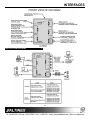
1
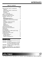
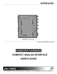
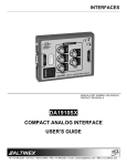
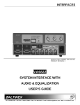
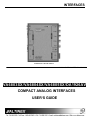
INTERFACES
VA6803SX is shown above
MANUAL PART NUMBER: 400-0154-003
VA6803SX/VA6804SX/VA6805SX/DA1926AV
COMPACT ANALOG INTERFACES
USER’S GUIDE
INTERFACES
TABLE OF CONTENTS
Page
PRECAUTIONS / SAFETY WARNINGS .............. 2
GENERAL ......................................................... 2
RACK MOUNT SAFETY GUIDELINES ............. 2
INSTALLATION ................................................. 2
CLEANING ........................................................ 2
FCC / CE NOTICE............................................. 2
ABOUT YOUR INTERFACE ................................. 3
TECHNICAL SPECIFICATIONS........................... 4
PRODUCT DESCRIPTION................................... 5
INPUT ............................................................... 5
MAIN RGBHV OUTPUT .................................... 5
LOCAL MONITOR OUTPUT ............................. 5
HORIZONTAL POSITION ADJUSTMENT
KNOB. ............................................................... 5
EXTERNAL POWER ADAPTER ....................... 5
MOUNTING CAPABILITY ................................. 5
AUDIO ............................................................... 6
BANDWIDTH..................................................... 6
EQUALIZATION ............................................... 6
APPLICATION DIAGRAM .................................... 8
INSTALLING YOUR INTERFACE ........................ 9
OPERATION ........................................................ 9
ACCESSORIES.................................................. 10
FAQ (FREQUENTLY ASKED QUESTIONS) ...... 11
JUMPER SETTINGS
.............................. 11
TROUBLESHOOTING GUIDE ........................... 12
ALTINEX POLICY............................................... 12
LIMITED WARRANTY..................................... 12
RETURN POLICY ........................................... 12
CONTACT INFORMATION ............................. 12
This manual covers:
VA6803SX - Compact Analog Interface with RGB
EQ + Audio
VA6804SX - Compact Analog Interface with RGB
EQ + Audio (Designed for use with
Remote H-Position & Signal LED)
VA6805SX - Compact Computer Video Interface
with RGB EQ
DA1926AV - Computer Video + Audio Distribution
Amplifier with dual 15-pin HD outputs (RGB EQ +
Audio)
1
INTERFACES
PRECAUTIONS / SAFETY WARNINGS
• Do not place the VA6803SX/ VA6804SX/
VA6805SX/DA1926AV Interface in direct
sunlight, near heaters or heat radiating
appliances, or near any liquid.
• Exposure to direct sunlight, smoke, or steam
can harm internal components.
the
VA6803SX/
VA6804SX/
• Handle
Interface
carefully.
VA6805SX/DA1926AV
Dropping or jarring can damage internal
components.
• Do not place heavy objects on top of the
VA6803SX/VA6804SX/VA6805SX/DA1926AV.
• Do not pull the adapter or any cable that is
attached to the VA6803SX/ VA6804SX/
VA6805SX/DA1926AV Interface.
1
Please read this manual carefully before using your
VA6803SX/VA6804SX/VA6805SX/DA1926AV
Interface. Keep this manual handy for future
reference. These safety instructions are to ensure
the long life of your VA6803SX/VA6804SX/
VA6805SX/DA1926AV and to prevent fire and
shock hazard. Please read them carefully and heed
all warnings.
1.1. GENERAL
• There are no user serviceable parts inside.
Only qualified ALTINEX service personnel must
perform all service on the VA6803SX/
VA6804SX/VA6805SX/DA1926AV.
1.2. SAFETY GUIDELINES FOR THE RACKMOUNTING OF THE VA6803SX/ VA6804SX/
VA6805SX/DA1926AV
• Maximum operating ambient temperature is 35
(degrees C).
• Never restrict the airflow through the devices’
fan or vents.
• When installing equipment into a rack,
distribute the units evenly. Otherwise,
hazardous conditions may be created by an
uneven weight distribution.
• Connect the unit to a properly rated supply
circuit.
• Reliable Earthing (Grounding) of Rack-Mounted
Equipment should be maintained.
• If the VA6803SX/ VA6804SX/ VA6805SX/
DA1926AV is to be mounted to a table or wall,
use
only
ALTINEX
made
mounting
accessories, such as brackets (MB1001) and
cables for optimum setup.
• If the VA6803SX/ VA6804SX/ VA6805SX/
DA1926AV Interface is not used for an
extended period, disconnect the adapter from
the wall to avoid fire, shock, and loss of power.
1.4. CLEANING
the
VA6803SX/
VA6804SX/
• Unplug
adapter
before
VA6805SX/DA1926AV
cleaning.
• Clean surfaces with a dry cloth. Never use
strong detergents or solvents such as alcohol
or thinner. Do not use a wet cloth or water to
clean the unit.
1.3. INSTALLATION
best
results,
place
the
• For
VA6803SX/VA6804SX/VA6805SX/DA1926AV
Interface on a flat, level surface in a dry area
away from dust and moisture.
• To prevent fire or shock, do not expose this unit
to rain or moisture.
• To turn off the main power, be sure to remove
the adapter from the wall. The power outlet
socket should be installed as close to the
equipment as possible, and should be easily
accessible.
1.5. FCC / CE NOTICE
• This device complies with part 15 of the FCC
Rules. Operation is subject to the following two
conditions: (1) This device may not cause
harmful interference, and (2) this device must
accept any interference received, including
interference that may cause undesired
operation.
• This equipment has been tested and found to
comply with the limits for a Class A digital
device, pursuant to Part 15 of the FCC Rules.
2
INTERFACES
These limits are designed to provide
reasonable
protection
against
harmful
interference when the equipment is operated in
a commercial environment. This equipment
generates, uses, and can radiate radio
frequency energy and, if not installed and used
in accordance with the instruction manual, may
cause
harmful
interference
to
radio
communications. Operation of this equipment in
a residential area is likely to cause harmful
interference in which case the user will be
required to correct the interference at his own
expense.
• Any changes or modifications to the unit not
expressly approved by ALTINEX, Inc. could
void the user’s authority to operate the
equipment.
ABOUT YOUR INTERFACE
VA6804SX/VA6805SX/DA1926AV provides two
fully buffered outputs: a main output on 5 BNC
connectors provides RGBHV, RGBS, or RGsB, and
a pass-through 15-pin HD monitor output. The
monitor output is typically used to transmit signals
to a local monitor. If the input signal format is
RGBS or RGBHV, the main output may be
RGBHV, RGBS, or RGsB. If the input signal is
RGsB, the output must be RGsB. The
VA6803SX/VA6804SX/ VA6805SX/DA1926AV is
not designed to separate sync from green.
The VA6803SX/VA6804SX/VA6805SX/DA1926AV
is capable of equalizing the attenuation effects of
long cable runs, up to 300 feet or more depending
upon the type of cable.
The VA6803SX/
VA6804SX/VA6805SX/DA1926AV accepts stereo
audio input and offers balanced or unbalanced
stereo audio output on a terminal block connector.
There is a 3.5mm jack for computer audio input,
which may be returned to the local audio system
with a 3.5mm jack for buffered stereo audio output.
A 5-pin terminal block is available for stereo audio
transmission to the main sound system. These
connectors are easily adaptable to stereo mini or
RCA type connectors.
2
There are a great variety of computers and
computer video cards on the market today. There
are also numerous data monitors and large screen
data projectors. When displaying a computer
image on a large screen data projector or on a
large screen monitor, it often becomes clear that
some computers are not always compatible with
these display devices. The VA6803SX/ VA6804SX/
VA6805SX/DA1926AV Computer Video Interface
that you have just purchased from ALTINEX is
designed to resolve this incompatibility.
Interface Capabilities
The VA6803SX/VA6804SX/VA6805SX/DA1926AV
is a high resolution computer video interface with
stereo audio designed to allow the connections of
VGA, SVGA, XGA, UXGA, MAC, SUN, SGI, and
other analog computer video sources to scan rate
compatible monitors, projectors, and LCD displays.
The VA6803SX/VA6804SX/VA6805SX/DA1926AV
amplifies video signals and converts sync to
various formats. It does not change the scan-rate
or the resolution of the video signal. The computer
and projector must be scan rate compatible with
each other.
The VA6803SX/VA6804SX/VA6805SX/DA1926AV
input is VGA compatible. The VA6803SX/
3
INTERFACES
TECHNICAL SPECIFICATIONS
FEATURES/
DESCRIPTION
GENERAL
No. of Inputs
Input Connector
No. of Outputs
Audio
1
3.5 mm jack (F)
2
Local Audio Output
3.5 mm jack
Connector
Local Monitor
—
Output Connector
Main Output
5-pin Terminal
Connector
Block
3
Input Sync Signals
Horizontal,
Vertical, &
Composite
Sync on Green
Impedance
Output Signals
Video
1
15-pin HD(F)
1 Main + 1 Local
Monitor
Level
—
15-pin HD
Female
Impedance
Gain
High Frequency
Gain
5 BNC Female
VGA/SVGA/XGA
/UXGA
Stereo or mono MAC/SUN/SGI
Compatibility
Audio
and other analog
computer video
sources
Table 1. VA6803SX/VA6804SX/VA6805SX/
DA1926AV General
Audio
Video
—
1.4V max
75 Ohms ± 1%
(terminated)
—
Impedance
10K Ohms
Max Level
0 dBu
TTL(+/-)
—
—
-0.3V
10k Ohms
—
1.7V p-p max
(terminated)
50 Ohms
(unbalanced), 100
Ohms (balanced)
—
—
Drive (w/ 600
>10 dBu
Ohms input)
Output Sync Signals
Composite,
Horizontal,
—
Vertical
Sync on Green
—
Impedance
—
Frequency Compatibility
Horizontal
—
Vertical
—
Minimum Video
—
Bandwidth
Audio Throughput
Horizontal
—
Position Range
MECHANICAL
Depth (inches)
4.3 in. (109mm)
Width (inches)
5.2 in. (132mm)
Height (inches)
1.0 in (25mm)
Weight (pounds)
1.0 lb. (0.45kg)
Ship Weight (pounds)
1.6 lb. (0.73kg)
Material
Aluminum
Finish
Paint, ALTINEX Grey
Top Panel
Lexan Overlay
T° Operating
10°C-35°C
T° Maximum
50°C
Humidity
90% non-condensing
MTBF (calculations)
40,000 hrs
Table 2. VA6803SX/ VA6804SX/ VA6805SX/
DA1926AV Mechanical
ELECTRICAL
Input Signals
Level
—
Cross-talk
Gain
Frequency
Response
Noise Floor
CMRR
—
+6 dB balanced, 0
dB unbalanced
10 Hz to 20 kHz
(+/-0.05 dB)
-98 dB @ 20 kHz
>40 dB, 10 Hz to
20 kHz
75 Ohms
0 dB
Adjustable by
equalization up
to 2 dB max
—
TTL(+/-)
-0.3V
22 Ohms
15 -130 kHz
25 -180 kHz
- 3dB @ 350
MHz
20%
20dB @
100MHz
—
—
—
—
Power
External Power
—
9V DC-500 mA
Adapter (DC)
Table 3. VA6803SX/ VA6804SX/ VA6805SX/
DA1926AV Electrical
4
INTERFACES
DESCRIPTION
4
CONNECTOR
Red Video
RED
Green Video
GREEN
Blue Video
BLUE
Horizontal or Composite Sync
H/C SYNC
Vertical Sync
V SYNC
Table 5. VA6803SX/ VA6804SX/VA6805SX (5BNC output pin-outs) DA1926AV (15-pin HD pinouts)
4.1. INPUT
The VA6803SX/VA6804SX/VA6805SX/DA1926AV
uses a 15-pin HD connector for input, which is
compatible with standard VGA pin-outs. This allows
the connection of a computer using coaxial cables
to a 15-pin HD connector cable. This allows greater
flexibility and versatility of the VA6803SX/
VA6804SX/VA6805SX/DA1926AV. The input and
output cables for various computers are available.
PINS
COMPUTER INPUT
1
2
3
4
5
6
7
8
Red Video
Green Video
Blue Video
Signal Return
Signal Return
Signal Return
Signal Return
Signal Return
9
Vesa 5V Input
4.3. LOCAL MONITOR OUTPUT
LOCAL MONITOR
OUTPUT
Red Video
Green Video
Blue Video
Signal Return
Signal Return
Signal Return
Signal Return
Signal Return
Composite Signal/
(No Connection for
DA1926AV)
Signal Return
Signal Return
N/C
A buffered output is very helpful in connecting your
local monitor to the interface. This output is fully
buffered; therefore, any reflections are totally
eliminated. The output is provided through a 15-pin
HD connector.
4.4. HORIZONTAL POSITION ADJUSTMENT
KNOB
Although most monitors and projectors are fully
capable of adjusting the horizontal position of the
image, in some instances it is helpful to adjust the
horizontal position at the interface. This control is
also helpful when using multiple computers.
Sync Return
Signal Return
SDA
Horizontal Sync/
Horizontal Sync
13
Composite Sync
Vertical Sync
Vertical Sync
14
SCL
N/C
15
Table 4. VA6803SX/ VA6804SX/ VA6805SX/
DA1926AV (15-pin HD) pin-outs
10
11
12
OUTPUT (5-BNC FEMALE)
In some cases, adjusting the horizontal position at
the interface may simplify the projector set up.
4.5. EXTERNAL POWER ADAPTER
The VA6803SX/VA6804SX/VA6805SX/DA1926AV
is powered using a 9VDC 500mA adapter. The
power regulation is provided inside the unit. The
adapter uses a 2.5mm connector with a center
conductor (+) and a shell (-). A selection of several
power adapters is available for different countries
from 110 VAC to 240 VAC.
4.2. MAIN RGBHV OUTPUT
BNC connectors
are considered
standard
connectors for audio-visual systems. They offer a
better quality connection for high-resolution video
signals. They also allow easy cable maintenance in
the field. This output offers RGBHV, RGBS, and
RGsB output signals (RGsB type input is passthrough only). With these connectors, the
VA6803SX/ VA6804SX/ VA6805SX can be
connected to compatible projectors using 4 coax or
5 coax cables.
4.6. MOUNTING CAPABILITY
The VA6803SX/VA6804SX/VA6805SX/DA1926AV
is designed for easy mounting to a table, wall, or
inside a rack using the MB1001 mounting brackets.
Two mounting holes are provided on each side of
the unit for the mounting brackets.
5
INTERFACES
4.7 AUDIO
the third harmonics of the video signal, thus
maintaining the highest quality of the input signal.
The VA6803SX/ VA6804SX/ DA1926AV accepts
stereo audio input and offers balanced or
unbalanced stereo audio output on a terminal block
connector. There is a 3.5mm jack for computer
audio input, which may be returned to the local
audio system with a 3.5mm jack for stereo audio
output. A 5-pin terminal block is available for stereo
audio transmission to the main sound system.
These connectors are easily adaptable to stereo
mini or RCA type connectors.
4.9 EQUALIZATION
Equalization is a means of boosting Red, Green,
and Blue signals at high frequencies with digital
adjustment knobs when using cable runs over 100
feet. This works for up to 300 feet or more of cable
depending on the type of cable. The attenuation of
red, green, and blue signals due to long cables may
be effectively removed.
4.8 BANDWIDTH
The minimum bandwidth is 350 MHz. This
exceptionally high bandwidth allows the passing of
DESCRIPTION (con’t)
6
INTERFACES
7
INTERFACES
APPLICATION DIAGRAM
5
8
INTERFACES
INSTALLING YOUR INTERFACE
Step 1.
Step 2.
Step 3.
Connect one end of the input cable to the
video output port of your source
computer and the 15-pin HD connector
end to the video input port of the
VA6803SX/ VA6804SX/ VA6805SX/
DA1926AV.
Step 5.
Connect one end of coaxial cable
between a projector/monitor and the
BNC connectors on the side of the
VA6803SX/ VA6804SX/ VA6805SX/
DA1926AV. Usually either a 4 BNC or 5
BNC coaxial cable is used, depending on
the display device’s requirement of
Composite SYNC (RGBS) or HSYNC &
VSYNC.
Step 8.
Adjust the red, green, and blue
equalization settings for the best image
quality.
OPERATION
7
The VA6803SX/VA6804SX/VA6805SX/DA1926AV
will operate successfully as long as cables are
attached properly and other technical specifications
are followed. There are no other adjustments
necessary to operate the unit.
Connect the cable from a local monitor to
the local monitor output of the
VA6803SX/ VA6804SX/ VA6805SX/
DA1926AV.
Also connect the audio cable from a local
audio amplifier to the local audio output
of
the
VA6803SX/
VA6804SX/
VA6805SX/ DA1926AV.
Step 7.
Step 9.
Also connect one end of the audio input
cable to the audio output port of your
source computer and the 15-pin HD
connector end to the audio input.
Step 4.
Step 6.
on the left side of the VA6803SX/
VA6804SX/ VA6805SX/ Interface with
the Horizontal Position Control knob in
the ON position.
6
7.1 HORIZONTAL POSITION CONTROL
When in the OFF position, the switch will disable the
adjustment of the horizontal position of the image
through the dial located on the input side plate. If
the Horizontal Position knob is in the ON position,
the horizontal position control of image is possible
through the knob on the side of the VA6803SX/
VA6804SX/VA6805SX/DA1926AV.
With the VA6803SX/ VA6805SX’s Horizontal
Position knob in the OFF position (Horizontal
position control disabled), it is recommended to first
adjust the horizontal position of the image using the
monitor or projector’s Horizontal Position control. If
the horizontal position of the image needs further
adjustments, adjust it with the dial located on the
VA6803SX/ VA6805SX Interface. The horizontal
position control is in the ON position at this time.
Also connect audio speaker wire from
the main sound system amplifier to the 5pin terminal block connector of the
VA6803SX/ VA6804SX/ VA6805SX/
DA1926AV.
To adjust the horizontal position of the VA6804SX,
connect the provided cable (CM11365) to the unit.
Then adjust the horizontal position control knob
located on the cable.
Connect the external power supply (AC
Adapter provided with the unit) with
2.5mm plug and 9V DC at 500mA output.
The power indicator light on the
VA6803SX/ VA6804SX/ VA6805SX/
DA1926AV should turn on.
7.2 SYNC ON GREEN
Often systems that use large matrix switchers are
designed to switch signals in RGsB format. This is
done to reduce the cost of the switcher and cable. In
these types of systems, the ability of the VA6803SX/
VA6804SX/ VA6805SX/ DA1926AV to output Sync
on Green can be very helpful. It is important to note
that the VA6803SX/ VA6804SX/ VA6805SX/
DA1926AV will not separate sync from the green
First, adjust the horizontal image
position using the monitor or projector
control. If further adjustments of the
image are needed, use the knob located
9
INTERFACES
signal, if the input signal is RGsB. It will simply
amplify video and pass it through. It will, however
combine Sync with Green Video when the switch is
in the ON position; regardless of whether the input
signal is RGBS or RGBHV.
ACCESSORIES
DA1926AV
Table 8. Selection of Interface Cables.
Model No.
Description
RACK MOUNT ACCESSORIES
Rack/Wall mount brackets for
MB1001
VA6800 series.
VGA+MAC INPUT & OUTPUT
COMBO-PACK
cables
VGA+MAC+SUN/SGI INPUT &
SUPER-PACK
OUTPUT cables
Table 9. Optional Accessories
8
Model No.
Description
9 V 500 mA Power Supply (requires
PS5502US
Adapter Cable)
PS5512UK 9 V 500 mA Power Supply for UK
PS5522AU 9 V 500 mA Power Supply for Australia
PS5532GR 9 V 500 mA Power Supply for Germany
PS5542JP 9 V 500 mA Power Supply for Japan
Table 7. Power Supply Selection.
Model No.
VGA-Pack
MS8125CA
MS8126CA
The standard cables are available 3 feet lengths.
Please call 1-714-990-2300 for a wider selection of
cables (6 ft, 12 ft).
Description
VGA Output cable for
VA6803SX/VA6804SX/VA6805SX/
DA1926AV
VGA Input cable for
VA6803SX/VA6804SX/VA6805SX/
DA1926AV
MAC–Pack
MS8121CA
MS8122CA
MAC Output cable for
VA6803SX/VA6804SX/VA6805SX/
DA1926AV
MAC Input cable for
VA6803SX/VA6804SX/VA6805SX/
DA1926AV
SUN/SGI–Pack
MS8123CA
MS8124CA
SUN Output cable for
VA6803SX/VA6804SX/VA6805SX/
DA1926AV
SUN Input cable for
VA6803SX/VA6804SX/VA6805SX/
DA1926AV
RGB-Pack
5 coax. (BNC) cable for
VA6803SX/VA6804SX/VA6805SX/
DA1926AV
Stereo/Mono
CB1206AU
Audio (3.5mm) cable for
VA6803SX/VA6804SX/VA6805SX/
10
INTERFACES
FAQ (FREQUENTLY ASKED QUESTIONS) 9
No:
1
Question
When and
why do I
need to
use the
Horizontal
Position
Control
Knob?
2
What
jumper do I
set to
receive the
composite
SYNC
output?
3
When and
why would
I use the
Sync on
Green
Jumper,
although
the unit
does not
separate
Sync from
Green?
When do I
use the HV
PRES
Jumper?
4
JUMPER SETTINGS
Answer
The Horizontal Position
Control Knob enables or
disables the control of the
horizontal position of the
image using the control knob
of the VA6803SX/
VA6804SX/ VA6805SX.
First, adjust the horizontal
position using the monitor or
projector control, and then
use the horizontal position
control of the VA6803SX/
VA6804SX/ VA6805SX, if
needed.
If the desired output signal is
composite sync, then set the
HV PRES Jumper (J5) to
OFF and connect only 4 wires
(RGBS) to RED, GREEN,
BLUE, and H/C SYNC
connectors. The default
position for J5 is ON.
The VA6803SX/VA6804SX/
VA6805SX does not separate
the Sync signal from the
Green signal, but if the
desired output is in RGsB
format regardless of the input
signal, set the SYNC ON
GREEN jumper (J2) to the
ON position. The default
position for J2 is OFF.
10
10.1 Accessing PC Board Jumpers
• Remove the two screws located on the bottom
side cover and carefully pull the top cover off.
•
Fit the top cover over the PC board and end
panels and replace the screws to reassemble
the unit. Make sure that the top cover label
matches the connectors.
P.C. Board Jumper Locations
If the desired output is in
RGBHV format, set the HV
PRES jumper (J5) to the ON
position. If the HV PRES
jumper is OFF then the
output signal may have
Composite Sync present on
the Horizontal Sync
connector.
11
INTERFACES
TROUBLESHOOTING GUIDE
•
Please make sure that the amplitude level of
the input signal is as follows:
a) RED, GREEN, and BLUE are less than
1.2 Volts.
b) HSYNC & VSYNC are less than 5.0 Volts
12.2. RETURN POLICY
•
Please use only an ALTINEX supplied power
supply (AC Adapter) for proper operation.
•
If problems show up on the display after
continuous usage at higher voltage, higher
temperature, higher humidity, or at other
extreme environmental conditions, please
correct those extreme conditions.
•
to affect its stability or reliability, or that has been
subject to misuse, negligence, or accident.
11
It is very important to ALTINEX that you receive the
products that you have ordered and that this product
fulfills your need. In the unlikely event, that
ALTINEX product needs to be returned please
follow policy below:
ALTINEX will accept product returns for period of 30
days from authorized ALTINEX dealers. Products
must be returned in an unopened package.
If product has been opened, the restocking fees will
apply. For restocking fee amount, please contact an
ALTINEX Sales Representative.
If the screen is large in the vertical direction
and if you are using Composite Sync on the
main output, please disconnect the V. SYNC
connector. Also, make sure that the HV PRES
Jumper (J5) is set to the OFF position.
•
First, adjust the horizontal position control of
the display and then use the horizontal position
control knob located on the VA6803SX/
VA6804SX/ VA6805SX, if needed.
•
If you are using RGsB format (Sync on Green),
make sure that the SYNC ON GREEN Jumper
(J2) inside of the unit is in the ON position.
ALTINEX POLICY
If product is in your possession for more than 30
days, the restocking fees will apply.
ALTINEX will not accept any returns on cables or
custom products.
If your product is in warranty and needs service,
contact the ALTINEX Sales Department for RMA
(Return Material Authorization). Products returned
without RMA number may experience a delay in
service.
If your product is out of warranty and needs service,
contact the ALTINEX Sales Department for RMA
(Return Material Authorization). Products returned
without RMA number may experience a delay in
service. The service charges will be quoted to you
before actual repairs are done.
12
12.1. LIMITED WARRANTY
ALTINEX warrants that its products and cables are
free from defects in materials under normal use and
service. This warranty is limited to repairing at
company’s factory any part or parts of the product,
which upon company’s examination shall disclose to
be, thus defective. Products considered defective
should be returned to company with transportation
charges prepaid within 2 years or (90 days for
cables) from date of shipment to the purchaser. The
warranty is expressly instead of all other warranties
expressed or implied. ALTINEX neither assumes
nor authorizes any other person to assume for it any
other liability concerning the sale of the products.
This warranty shall not apply to any product that
shall have been repaired or altered outside of
company’s factory in any way so as, in its judgment,
12.3. CONTACT INFORMATION
ALTINEX, INC.
592 Apollo Street
Brea, CA 92821 USA
TEL: 714-990-2300
TOLL FREE: 1-800-ALTINEX
WEB: www.altinex.com
E-MAIL: [email protected]
FAX: 714-990-3303
12