
1
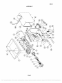
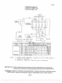
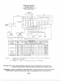
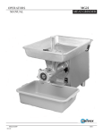
INSTRUCTION
MANUAL
Meat Grinder
Persons under age 18 are not permitted to operate or
have accessibility to operate this equipment per
U.S. Dept. of Labor Employment Standards
Administration Fact Sheet No. ESA91-3.
univex
MG22/0603
ED 3
PDF compression, OCR, web optimization using a watermarked evaluation copy of CVISION PDFCompressor
TO
INSURE
BOTH
SAFE
AND
TROUBLEFREE PERFORMANCE WE STRESS
THAT
ALL
PERSONNEL
THAT
WILL
BE
INVOLVED WiTH YOUR NEW UNIVEX MEAT
GRINDER MUST READ AND UNDERSTAND
THESE INSTRUCTIONS BEFORE ATTEMPTING
TO OPERATE THIS UNIT.
WE APPRECIATE YOUR COOPERATION AND
YOUR BUSINESS.
SHOULD THERE BE A
QUESTION OR IF WE CAN BE OF FURTHER
ASSISTANCE,
PLEASE
CALL
US,
I 6O3-893-61 91.
PDF compression, OCR, web optimization using a watermarked evaluation copy of CVISION PDFCompressor
MG22
TABLE OF CONTENTS
DESCRIPTION
PAGE
Table of Contents
Operator Safety
Installation
Assembly and Operating Instructions
Cleaning
Parts List
Assembly
2
2 -3
3
4-5
Wiring Diagram 115/208-230V, 60HZ, IPH / 220-240V, 50HZ, IPH
Wiring Diagram, Canada, CE, 115/208-240V, 60HZ, IPH / 230V,50HZ, IPH
Warranty Information
6
7
8
Back Cover
MG22 MEAT GRINDER
INSTRUCTION MANUAL
Inspection:
All Univex MG22's are inspected prior to packaging to assure both the machine quality, correct
inclusion of options, and proper voltage. However, upon unpacking, all items should be carefully
verified that they are correct, Any damage, imperfection, or shortages should be reported immediately
to your dealer or directly to Univex Customer Service, and/or shipment carrier.
Operator Safety:
It is a violation of the United States Department of Labor regulations to permit operation of
the MG22 by any person under the age of 18 years.
Read and understand all instructions and safety warnings prior to operating unit.
Never put fingers or any utensils (other than the stomper (Item 10) in the throat or entry of the
grinder, or in the kniíb and plate area of the grinder. This is a powerThl unit designed to grind
meat; use extreme caution and avoid exposing body parts to grinding and cutting areas of the unit.
Switch the power off and disconnect the electric power supply prior to mounting and dismounting
the grinder, cleaning, or servicing.
Knife is sharp and can cut finger. Use caution when handling.
Always have chopper securely mounted, worm assembly fully coupled onto drive coupling, and the
knife, plate, and ring snugged on before switching the power on.
Always remove the grinder from the power drive before cleaning; never rinse with hose while
mounted to power source, inviting electrical shock.
Page 1
PDF compression, OCR, web optimization using a watermarked evaluation copy of CVISION PDFCompressor
MG22
Installation;
This is a table-top unit. Unit may be secured to table top via the shipping bolt threaded holes on the
power drive housing bottom.
Insure the unit is located such that it is placed on a level and stable surfàce, and sufficient clearance
is provided all around the unit for safrty and ease of operation. Proper location includes space for
the feed pan and clip-on storage container,
Feed pan support bracket (Item 45) must be assembled onto the housing cover (Item 43) using the
screws (Item 46) provided.
ASSEMBLY AND OPERATING INSTRUCTIONS;
Introduction:
The Univex MG22 Meat Grinder consists of a I H.P. electric motor power base which drives a
bell-shaped meat grinder designed to utilize industry standard #22 knives and full range of #22 grinding
plates. Included as standard equipment is a carbon steel knife (Item 3), 3/16 grinding plate (Item 2),
aluminum meat stomper (Item 10), 16 x 24 aluminum feed pan (Item 9) for holding meat to be
processed, and t8.5 x 13.5 storage container with lid för collecting meat as it is processed.
The Univex MG22 has safety and ease of operation built into it. The permanent safety guard positioned
over the bell-shaped feed hopper prevents accidental entry of operator's fingers and hands into the
grinding zone, The readily removable feed pan and storage container provide for ease of processing and
cleaning.
Noise emissions below 70 db(A).
Assembly:
WARNING: Disconnect power supply prior to assembly.
Mount the housing-guard assembly (Item 8) to the housing weldment (Item 26) by firmly
tightening knobs (Item 12) onto mounting studs (Item 14).
Slide the worm assembly (Items 6,5,4) into the housing-guard assembly (Item 8) and mating into
the drive coupling (Item 15).
Slide the knife (Item 3), sharp edges toward the plate, onto the square of the worm assembly (Item
4). Slide the plate (Item 2) onto the worm assembly (Item 4). Screw the ring (Item 1) onto the
housing-guard assembly (Item 8) until it is just snug. Too much pressure can damage the unit.
WARNING: The knife is sharp and can cut fingers.
Guide the feed pan (Item 9) over the guard portion of the housing-guard assembly (Item 8) onto
the pan stud (Item 7) and the pan support (Item 44).
S. Locate the storage container under the clip (Item 24) and resting on the front legs (Item 23).
6. Connect power supply and actuate power switch (Item 25).
WARNING: Never put fingers or utensils in the throat of the grinder or the knife and
plate interface.
Page 2
PDF compression, OCR, web optimization using a watermarked evaluation copy of CVISION PDFCompressor
MG22
Process
Cut meat to be processed to fit under or through the safety guard. Recommended size is 1 '/2' thick
x 3" wide x 12" long. Set meat in pan (Item 9).
With grinder running, slide product under the guard of the housing-guard assembly (Item 8) or
through the openings in the guard top. Use the meat stomper (Item 10) if desired, to guide
product into grinding zone. The stomper is recommended for regrind.
Collect ground product in storage container,
Cleaning:
Turn unit off and disconnect from power supply.
Disassemble unit in reverse of assembly instructions - Remove storage container, feed pan, and
then ring, plate, knife, worm assembly, and housing-guard assembly.
WARNING: The knife is sharp and can cut fingers.
Clean components including the drive coupling (Item 15) by following the procedure: wash, rinse,
sanitize, and air dry. Use the bristle brush provided to clean areas diflicult to access, Apply a
small amount of food grade lubricant to bronze bushing, located inside the housing-guard
assembly (item 8), before use.
Page 3
PDF compression, OCR, web optimization using a watermarked evaluation copy of CVISION PDFCompressor
MG22
ILLUS.
1
2
3
4
5
6
7
8
9
10
11
12
13
14
15
16
17
18
19
20
21
22
23
24
25
26
27
28
29
30
31
32
33
34
35
36
PART NO.
1000719
1000727
1000726
1000728
1000729
1000730
1000725
1000715
1000711
1000717
1000731 *
1000709 *
8700214
1000735
1000724
8700222
4400275
1000718
1000713
1200412
1200359
1000722
4400500
4400015
8700219
8700220
8700211
8700216
8700218
8700210
1200432
7100103
7100023
1024414
1200433
1200076
4400065
1200060
7510252
7100011
7100015
7100012
7 100040
37
38
39
40
41
7100116
7100108
7100016
7100010
4400155
4400005
1814118**
8512855
ASSEMBLY
DESCRIPTION
QTY.
RING,#22
PLATE, 3/16"
PLATE 1/8' (OPTIONAL)
PLATE 1/4' (OPTIONAL)
PLATE 3/8' (OPTIONAL)
PLATE 1/2' (OPTIONAL)
KNIFE, #22
ShAFT, FRONT
WORM, #22
COUPLING, WORM
STUD, PAN
ROUSING-GUARD ASSY
PAN
STOMPER
LOCK PIN, PLATE
KNOB
STUD - SWITCH ACTUATOR
STUD, MOUNTING
COUPLING, DRIVE
2
2
SETSCREW 1/4-20X1/4CUppT
2
6
SCREW HEX. RD. SS CAP 3/8-16 X 1 1/2" LOE
WASHER, MOTOR
I
KEY 1/4SQ.X1 1/2
KEPNUT 3/8-16
8
GEAR MOTOR
SLEEVE, FRONT LEG
2
LEG, FRONT
2
CLIP, BUSS BOX
SWITCH, START/ STOP
HOUSING, WELDMENT
SCREW HEX. RD. CAP 4-40 X 3/4 LOE
SWITCH, SAFETY
INSULATOR, SAFETY SWITCH
BRACKET, SAFETY SWITCH
ELASTIC STOP NUT 4-40
WASHER 10
LOCK WASHER 10
HEXNUT1O-32
ELASTIC STOP NUT - MIO X 1.5
CONTACTOR 115V, 60HZ.
CONTACTOR 100V, 50-60HZ
CONTACTOR 230V, 60HZ
STARTER, 115V, 60HZ (CANADA ONLY)
STARTER, 230V, 60HZ, (CANADA ONLY)
STARTER, 230V, 50HZ, IPH (EUROPE ONLY)
CONTACTOR, 220-240V, 50HZ,
RAIL, DiN
SCREW HEX. RD. CAP 1/4-20 X 1/2 LOE
LOCK WASHER 1/4
LEG,REAR
FEET, REAR
I
2
1
I
2
6
6
7
2
1
I
2
2
2
2
Page 4
PDF compression, OCR, web optimization using a watermarked evaluation copy of CVISION PDFCompressor
MG22
ILLUS.
42
43
44
45
46
47
48
49
50
51
52
53
54
55
56
57
PART NO.
7100107
8700212
8700215
8700217
4400246
1200012
8700014
8700105
8800200
8800208
4400326
4400351
1000732
4400401
8800229
DESCRIPTION
QTY.
STRAIN RELIEF
COVER, HOUSING
SUPPORT, PAN
SLEEVE, PAN SUPPORT
SCREW, FLAT RD SLT SS 10-32 X 3/4
1
SCREWPPHD.10-32X1/2LG.
6
RUBBER STRIP
STORAGE CONTAINER (NOT SHOWN)
POWER CORD (NOT SHOWN)
CORD, MOTOR (NOT SHOWN)
LABEL, UNIVEX (NOT SHOWN)
LABEL, (NOT SHOWN)
RESERVED
BRUSH, CLEANING (NOT SHOWN)
CONNECTOR. 3/8 (NOT SHOWN)
WIRING PKG. (NOT SHOWN)
2
2
1
1
* ILLUS. NO. 71S INCLUDED WITH ILLUS. NO 8
** ILLUS. 40 INCLUDES STUD M10-1.5 X 22MM
Page 5
PDF compression, OCR, web optimization using a watermarked evaluation copy of CVISION PDFCompressor
PDF compression, OCR, web optimization using a watermarked evaluation copy of CVISION PDFCompressor
MG22
WIRING DIAGRAM
115/208-230V, 60HZ, IPH
220-240V, 50HZ, IPH
/
POWER N
BLACK WI-tIE GND
WI
4,
r
SAFETY
SWITCH
L3cr
J. MAGNETIC
L
CONTACTOR
I3h]
14 I
-J
W7
W2
W4
STOP
PWTCH
I
I
,I
L,._ J
I,,
W3
I..
LI
WIRE
NUMBER
NO.
WI
SEE
NOTE
ABLE
LENGTH
END A
END B
COLOR
l4 INCHES SEE NOTE SEE NOTE
5
16
W3
IS
3
3
3
W4
6
3
W5
IS
IS
3
3
2
16
3
2 (/2
W7
NOTES:
MOTOR
W2
we
8800208
GA
W8
o-f---WIRE
PART
8800229
W5
START
SWITCH
W8
33
-
13
2
(/2
24
25
(/2
I
WHITE
WHITE
I
2
I
2
1
I
RED
1
I
BLACK
I
I
I
I
RED
RED
I
RED
MOTOR CORD
I. DOUBLE CRIMP FERRULES, KLAUKE 72/IOVZ OR AMP 925553-2,
MOLEX-ETC BB-5623.
MATERIAL: I6GA 1015 TEW CSA AND UL APPROVED.
IMPORTANT; Before making electrical connections, check the specifications on the data plate
(located on the rear panel) to assure they agree with those ofyour electrical service.
WA.RNJNG: Whenever maintenance is being performed, or whenever the top cover has been removed,
DISCONNECT electrical cord and place a tag on it indicating the slicer is being worked on.
Page 7
PDF compression, OCR, web optimization using a watermarked evaluation copy of CVISION PDFCompressor
WIRING DIAGRAM
CANADA & CE
115/208-240V, 60HZ, IPH
230V, 50HZ, 1PH
POWER IN
/
I
9
-
W6
SAFETY
SWITCH
-
S
AI
LI
L2
A2
TI
T2°T3\,0
L3
STARTER
i
r
W8
L2 L3 ONO
LI
WI
L_ _..J
OVERLOAD RELAY
JD
13
.-O
_95
TI
14
W7
W2
W4
STOP
SWITCH
START
\
SWITCH
W9
I
MOTOR
I
H..
.1
W3
o
W5
WIRE TABLE
PART
NUMBER
8800229
WIRE
LENGTH
SEE
NOTE
NO.
END A
END B
'COLOR
IN INCHES SEE NOTE SEE NOTE
WI
16
3
33
I
2
W2
6
3
13
I
2
W3
16
3
I
I
RED
W4
6
6
3
I
I
BLACK
I
I
RED
3
2
I
I
RED
3
5
I
I
RED
WS
NOTES:
GA
PART
W6
OF
W7
16
16
STARTER
WI
16
8800208
WO
1/2
2
24
26
3
3
8
1/2
1/2
1/2
I
I
WHITE
WHITE
RED
MOTOR CORD
I, DOUBLE CRIMP FERRULES. KLAUKE 72/IOVZ OR AMP 925553-2
MOLEX-ETC BB-5623.
MATERIAL:
I6GA 1015 TEW OSA AND UL APPROVED.
IMPORTANT: Before making electrical connections, check the specifications on the data plate
(located on the rear panel) to assure they agree with those of your electrical service.
WARNING; Whenever maintenance is being performed, or whenever the top cover has been removed,
DISCONNECT electrical cord and place a tag on it indicating the slicer is being worked on.
Page 8
PDF compression, OCR, web optimization using a watermarked evaluation copy of CVISION PDFCompressor


![10780-90006 - 10780A Laser Receiver for 5501A [Prefix 1948] (Mar](http://vs1.manualzilla.com/store/data/006009643_1-6e2f54ebb2199ef6df634558ba4c1bb6-150x150.png)