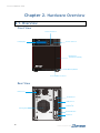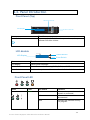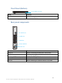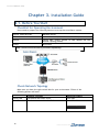
1
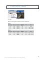
SMR5016/5020 Smart Megapixel Video Recorder Hardware Manual Release 1.0 August, 2011 All Rights Reserved © Surveon Technology 2011 Copyright Statement No part of this publication may be reproduced, transmitted, transcribed, stored in a retrieval system, or translated into any language or computer language, in any form or by any means, electronic, mechanical, magnetic, optical, chemical, manual or otherwise, without the prior written consent of Surveon Technology Inc. Disclaimer Surveon Technology makes no representations or warranties with respect to the contents hereof and specifically disclaim any implied warranties of merchantability or fitness for any particular purpose. Furthermore, Surveon Technology reserves the right to revise this publication and to make changes from time to time in the content hereof without obligation to notify any person of such revisions or changes. Product specifications are also subject to change without notice. Trademarks Surveon and Surveon logo are trademarks of Surveon Technology Inc. Other names prefixed with “SMR” are trademarks of Surveon Technology Inc. Microsoft Windows and Windows are registered trademarks of Microsoft Corporation. Linux is a trademark of Linux Torvals. Solaris and Java are trademarks of Sun Microsystems, Inc. All other names, brands, products or services are trademarks or registered trademarks of their respective owners. 2 Table of Contents Copyright Statement .........................................................................2 Safety Precautions ............................................................................5 Device Site Recommendations..............................................................5 Regulatory Compliance Information .......................................................6 Revision History ...............................................................................8 Chapter 1. Product Overview...............................................................9 1.1. Features and Benefits ...............................................................9 1.2. Specifications for the SMR Series .................................................9 Hardware Specifications ................................................................ 9 VMS Specifications ....................................................................... 9 Chapter 2. Hardware Overview .......................................................... 12 2.1. Overview............................................................................. 12 Front View .............................................................................. 12 Rear View ............................................................................... 12 2.2. Panel Introduction ................................................................. 13 Front Panel (Top) ...................................................................... 13 LCD Module.............................................................................. 13 Front Panel LED ........................................................................ 13 Front Panel (Bottom) .................................................................. 15 Rear panel components ............................................................... 15 Chapter 3. Installation Guide ............................................................. 16 3.1. Before You Start.................................................................... 16 Checklist for Operating Environment................................................ 16 Check Network Topology.............................................................. 16 3.2. Hard Drive Installation ............................................................ 17 Hard Drive Installation Prerequisites ................................................ 17 Placing Hard Drive into Drive Tray .................................................. 17 Inserting Hard Drive into Drive Tray................................................. 17 3.3. Cabling ............................................................................... 19 3 3.4. Powering up SMR ................................................................... 20 3.5. Resolution Setting.................................................................. 21 3.6. Storage Management .............................................................. 23 3.7. Configuring an IP Address for NVR Server ..................................... 26 3.8. Adding Network Cameras to the Server........................................ 27 Auto Scanning for Camera ............................................................ 27 Manually Adding Cameras ............................................................. 28 3.9. Initializing the Camera ............................................................ 29 3.10. Setting up Live View ............................................................. 30 4 Safety Precautions Electric Shock Warning This equipment may cause electric shocks if not handled properly. Access to this equipment should only be granted to trained operators and maintenance personnel who have been instructed of, and fully understand the possible hazardous conditions and the consequences of accessing non-field-serviceable units such as the power supplies. The system must be unplugged before moving, or in the even that it becomes damaged. Reliable Grounding Particular attention should be given to prepare reliable grounding for the power supply connection. It is suggested to use a direct connection to the branch circuit. Check for proper grounding before powering on the device. Overloading Protection The device should be installed according to specifications. Provide a suitable power source with electrical overload protection. Do not overload the AC supply branch circuit that provides power to the device. ESD Precautions Please observe all conventional anti-ESD methods while handling the device. The use of a grounded wrist strap and an anti-static work pad are recommended. Avoid dust and debris in your work area. Device Site Recommendations The device should be installed according to specifications. This device should be operated at a site that is: Clean, dry, and free of excessive airborne particles. Well-ventilated and away from heat sources such as direct sunlight and radiators. Clear of vibration or physical shock. Away from strong electromagnetic fields produced by other devices. Available with properly grounded wall outlet for power. In regions where power sources are unstable, apply surge suppression. Available with sufficient space behind the device for cabling. 5 Regulatory Compliance Information Regulatory Compliance Information FCC/CE Class A IEC 60950 Shown below is the location of the compliance statement label. FCC (applies in the U.S. and Canada) FCC Class A Radio Frequency Interference Statement This equipment has been tested and found to comply with the limits for a Class A digital device, pursuant to Part 15 of the FCC Rules (47 CFR, Part 2, Part 15 and CISPR PUB. 22 Class A). These limits are designed to provide reasonable protection against harmful interference when the equipment is operated in a residential installation. This equipment generates, uses, and can radiate radio frequency energy and, if not installed and used in accordance with this user’s guide, may cause harmful interference to radio communications. However, there is no guarantee that interference will not occur in a particular installation. If this equipment does cause harmful interference to radio or television reception, which can be determined by turning the equipment off and on, you are encouraged to try to correct the interference by one or more of the following measures: Reorient or relocate the receiving antenna. Increase the separation between the equipment and receiver. Connect the equipment into an outlet on a circuit different from that to which the receiver is connected. Consult the dealer or an experienced radio/TV technician for help. This device complies with Part 15 of FCC Rules. Operation is subject to the following two conditions: 1) this device may not cause harmful interference, and 2) this device must accept any interference received, including interference that may cause undesired operation. Warning! A shielded power cord is required in order to meet FCC emission limits and also to prevent interference with nearby radio and television reception. Use only shielded cables to connect I/O devices to this equipment. You are cautioned that changes or modifications not expressly approved by the party responsible for compliance could void your authority to operate the equipment. 6 This device is in conformity with the EMC. Notice for Class A Product This notice is for class A product only. If the equipment under test is a class B product, this notice should be disregarded. Class A ITE is a category of all other ITE which satisfies the class A ITE limits but not the class B ITE limits. Such equipment should not be restricted in its sale but the following warning shall be included in the instruction for use. Warning: This is class A product. In a domestic environment this product may cause radio interference in which case the user may be required to take adequate measures. Surveon is committed to being properly prepared and taking all the necessary steps that will result in our compliance with the new European directive, RoHS (2002/95/EC), on or before the specific dates set forth in those applicable laws and regulations. Surveon is applying its own internal efforts and expertise and is working closely with customers and suppliers to achieve compliance while maintaining an uninterrupted supply of quality products. Surveon is currently investigating, evaluating, and qualifying our materials and components to ensure that products sold on or after 1 July 2006, in such territory, are in compliance with the above regulations. Disposal of Old Electrical & Electronic Equipment (Applicable in the European Union and other European countries with separate collection systems) This symbol on the product or on its packaging indicates that this product shall not be treated as household waste. Instead it shall be handed over to the applicable collection point for the recycling of electrical and electronic equipment. By proper waste handling of this product you ensure that it has no negative consequences for the environment and human health, which could otherwise be caused if this product is thrown into the garbage bin. The recycling of materials will help to conserve natural resources. 7 Revision History 8 Version Description Date 1.0 Initial release August 2011 Chapter 1. Product Overview 1.1. Features and Benefits The Surveon SMR series is a state-of-the-art network video recorder features hardware RAID, low power and hot swappable hard disks. With 2/5/8-bay hard disk trays, the SMR series is the best in class NVR that supports megapixel quality video of 6 to 32 channels for video retention periods from 7 to 30 days or more. In addition, the SMR series is fully burn-in-tested and uses preloaded Surveon Enterprise VMS to eliminate compatibility issues while reducing maintenance overheads. It is out of question that the SMR series is the most reliable and costeffective solution for small to medium sized surveillance needs. 1.2. Specifications for the SMR Series Hardware Specifications System Processor System Memory Chipset Disk on Module Storage I/O Interface H/W RAID Electrical Operating Environment LCD Panel LED Indicator Dimensions Weight Certificate SMR5016/5020 Intel ® ATOM525 Dual Core @ 1.8 GHz DDR3 2GB Intel ® ICH9R 4GB 3.5” SATA HDDs x5 ; HDD hot swappable VGA: 1xD-Sub RJ-45: 2x1 Gigabit Ethernet USB: 4x USB2.0 E-SATA: x1 RAID 0, 1, 5 Input Voltage: 100V~240V, 1.5A Frequency: 50Hz~60Hz Power Consumption (in operation): 43W In operating Humidity: 5% to 80% (non-condensing) Temperature: 5°C to 40°C Yes Yes 190(H) x 110(W) x 245(D) mm 5 kg (without hard drives) BSMI, CB, FCC / CE Class A , UL60959/ IEC60950, GOST VMS Specifications Live View • • • • • • Real-time network camera discovery Versatile views of various screen divisions HTML and image overlays Multiple views supported View patrolling for single or multiple views Real time vidoe/event alarm display Surveon Smart Megapixel Video Recorder Hardware Manual 9 Surveon SMR5016/5020 eMAP PTZ Investigation Instant Playback Video Intelligence Remote Management 3rd Party IPCAM General & Misc 10 • Instant playback • Video clip bookmarking • Drag-n-drop camera manipulation • Directional camera display • Hierarchical map structure • Real time event alert • Instant live video of camera • Multiple maps supported • Pan, tilt, zoom operations (dependent of the camera) • Built-in, floating PTZ control panel • Preset position (dependent of the camera) • Scheduled or continous camera patrolling • Event-driven camera patrolling • Search by date, time, camera • Search by pre-defined recent time • Search by VI event combinations • Search over multiple days • Search over multiple cameras • Video clip bookmarking and commenting • Search via built-in VI analyzer • Customizable bookmark • Intuitive, video thumbnail search results • Cue-in, cue-out and repeat • Quick playback by video thumbnail • 1/8, 1/4, 1/2, 1x, 2x, 4x, 8x play, pause, stop • AVI-formated video clip export • Supported in video alarm, event alarm, view functions • Pre-defined playback durations • Video clip bookmarking • General motion detection • Missing object detection • Foreign object detection • Intrusion detection • Forbidden area detection • Tampering detection • Virtual fence* • Object counting* Full functional operation & management via standalone VMS Client AXIS, SONY, Panasonic, Mobotix, Arecont Vision, IQinVision, Zavio, VIVOTEK, ACTi, D-Link, Asoni, AVTech • Video codec: H.264, MPEG4, MJPEG • Image enhancement • Video privacy mask • Digital zoom in, zoom out • Log viewer • Windows lockup • Client auto login • Digital I/O management • Automatic storage recycling • Client-server architecture • Guaranteed performance of long period recording www.surveon.com • Configurable video retention period • Digital watermark proofing* • Language supported: English, French, German, Portuguese, Spanish, Simple Chinese, Traditional Chinese Surveon Smart Megapixel Video Recorder Hardware Manual 11 Surveon SMR5016/5020 Chapter 2. Hardware Overview 2.1. Overview Front View LED Indicators SMR LCD Display SELECT Power Switch EN T ER Hard Drives (Inside the Cabinet) Video Back Up Button Front USB Connector Rear View Power Port E-SATA Port USB Port x 4 1 LAN Port x2 Cooling Fan 2 Restore Button VGA Port 12 www.surveon.com 2.2. Panel Introduction Front Panel (Top) LED Indicators S MR SELECT LCD Display ENTER Power Switch Name Function Power Switch Powers up the SMR. When the power is on, the power indicator will shine in blue. LCD Module S MR LCD Display Select Switch Enter Switch Name Function LCD Display Shows system messages. Select Switch Shows the menu for choosing RAID0, RAID1, or RAID5. Enter Switch Confirms the options and functions after the Select Switch is used. Front Panel LED Name Color LED Status Function Network Green On Indicates that power is on and network is connected. Indicates that network is disconnected. Indicates that network activity is in progress. Off Blink Surveon Smart Megapixel Video Recorder Hardware Manual 13 Surveon SMR5016/5020 HDD Amber On Off Blink System Red On Blink 14 Indicates that the hard drive can be accessed. Indicates that a hard drive read/write error occurred. Indicates one of the followings: (1)Disk volume creation is in progress. (2)Online RAID level migration is in progress. (3)RAID rebuilding is in progress. Indicates the system fan is malfunctioning. Indicates that system is starting up. www.surveon.com Front Panel (Bottom) Front USB Connector Name Function Front USB Connector Connects external accessories such as mouse, keyboard or other external devices. Rear panel components E - SATA Port USB Port 1 LAN Port 2 Restore Button VGA Port Name Function E-SATA x1 USB Port x 4 Used for connecting the SMR with E-SATA drives. Used for exporting video clips as evidence support to external storage devices. Used for connecting the SMR with the network. Reserved Used for attaching an external monitor to the SMR. LAN Jack (GbE Ethernet port) x2 Restore Button VGA Port Surveon Smart Megapixel Video Recorder Hardware Manual 15 Surveon SMR5016/5020 Chapter 3. Installation Guide 3.1. Before You Start Checklist for Operating Environment Users need to prepare the following devices to set up the surveillance system. Network Video Recorder SMR5000 series IP Camera Network Network Cameras (such as Surveon CAM5210) Existing LAN, Switch, Router or Hub (please see the Network Topology below) Hard Drives Storage Note: The hard drives should be purchased separately. Check Network Topology Make sure you have the right switch/hub for your environment. Either of the following options will work. Existing LAN Router 16 Common Topology LAN Switch with DHCP Server LAN Switch with build-in DHCP Server Reference Product Office LAN D-Link DIR-130 www.surveon.com Switch/Hub No DHCP Server(refer to the Note below) D-Link DES-1108 Note: For devices without DHCP Server function, please refer to section 3.7. 3.2. Hard Drive Installation Hard Drive Installation Prerequisites When purchasing hard drives, the following factors should be considered: Capacity (MB/GB): Use drives with the same capacity. (The maximum is 2TB.) Drive type: The system uses SATA interface 3.5-inch hard drives. Please ensure that you purchase the correct hard drives. Placing Hard Drive into Drive Tray Place the hard drive into the drive tray, making sure that the interface connector is facing the open side of the drive tray and its label side facing up. 5th 1st Inserting Hard Drive into Drive Tray 1. Make sure the rotary bezel lock is in the unlocked position as shown in the figure below (i.e., the groove on its face is in a horizontal orientation). Use a small-size flatblade screwdriver to turn the bezel lock. Surveon Smart Megapixel Video Recorder Hardware Manual 17 Surveon SMR5016/5020 2. Open the bezel by pressing the release button on the front flap. The front flap will automatically swing open. 3. Align the drive tray with the tray slot into which you wish to insert it. Make sure that it is properly aligned, and then gently slide it in. Note: While replacing hard drives, users can only extract one drive tray at a time. WARNING All drive bays must be populated even if it does not contain a hard drive. With one or several empty bays, ventilation will be disrupted and the SMR will overheat. 18 www.surveon.com 4. Close the front flap of the front panel. Make sure the front flap is closed properly to ensure that the connector at the back of the hard drive is firmly connected to the corresponding connector on the backplane board. 5. Once all drive trays are properly installed, the SMR system will recognize the disk drives and scan them in automatically during the power-on procedure. 3.3. Cabling Connect cables to the rear panel ports as follows. USB Port 1 LAN Port 2 VGA Port Insert mouse, keyboard or other external devices to the USB port to operate the Video Management Software (VMS). Insert the LAN cable to the upper LAN port to connect the SMR to a local network where your IP cameras reside. (Connection to analog cameras is also available via an IP encoder.) Connect an external monitor capable of 32bit or higher color quality to the VGA Port to view the VMS interface. Connect the power cord to the power port and available outlet. Note: (1) The LAN cable should be prepared by users. (2) Users can only use the upper LAN port. Surveon Smart Megapixel Video Recorder Hardware Manual 19 Surveon SMR5016/5020 3.4. Powering up SMR LED Indicators S MR SELECT LCD Display ENTER Power Switch 1. Press the Power Switch. 2. See if the System LED is blinking, which means the system is starting up. 3. See if the Network LED has turned green, which indicates power is on and network is connected. 4. See if the HDD LED is on, which means the hard drive can be accessed. 5. See if the IP address of the VMS Server is shown on the LCD display. 20 www.surveon.com 3.5. Resolution Setting The default monitor resolution for the SMR is 1280x1024, and if the resolution of your monitor is lower than this value, the following warning message will prompt out. To change the resolution setting, please follow the steps below: 1. Press Ctrl+Shift+Esc to call the task manager. 2. Go to File> New Task (Run…) and then type “explorer” in the “Create New Task” dialogue. 3. The Explorer Window will appear. Click Open Control Panel on the right top. Surveon Smart Megapixel Video Recorder Hardware Manual 21 Surveon SMR5016/5020 4. Click Intel(R) GMA Driver in All Control Panel Items table. 5. Choose Single Display as the operating mode and Monitor as the display selection in Display Devices. Change the screen resolution in Display Settings. Click OK to finish. 22 www.surveon.com 3.6. Storage Management Follow these steps to make sure the RAID configuration and initialization are complete before the recording starts. 1. When the SMR is starting up, the VMS Client will start automatically. Use the following default account to login to the VMS. Username: admin Password: admin 2. Go to Server Setting > Storage Manager under the Server entry. All available Logical Drives, as well as their sizes, free space, and status will appear. Clicking the target drive first and then Settings will allow users to create a RAID configuration onto integrated external RAID drives. 3. In the “Advanced Settings” dialogue, “General” tab, click Check to check the system for available external RAID drives. Surveon Smart Megapixel Video Recorder Hardware Manual 23 Surveon SMR5016/5020 4. Choose the RAID level, and then click ”Create Logical Drive” to create the RAID configuration. ※ These are default RAID configurations for the SMR models, optimized for I/O performance. Model Number of Hard Drives Detected(2TB ) 5 Total Size Default RAID Configuration Notes 8TB RAID5 Normal application with 1 disk failure protection SMR5016/5020 4 6TB RAID5 Normal application with 1 disk failure protection 5 10TB RAID0 Normal application with no protection 5. RAID initialization will begin when all the hard drives are installed. A warning message will jump out when the initialization is in progress. Click OK. Note: RAID initialization for SMR series will take about 28 hours (5 pieces of 2TB hard drives)/ 18.5 hours (5 pieces of 1TB hard drives) for RAID 5. 6. After initialization is complete, please restart the system. 24 www.surveon.com 7. Go back to the Storage Manager to check if the RAID is configured successfully. Surveon Smart Megapixel Video Recorder Hardware Manual 25 Surveon SMR5016/5020 3.7. Configuring an IP Address for NVR Server Before NVR Server can run successfully, an IP address must be properly bundled with it. Note: (1) You may skip these steps if your routing devices have DHCP capabilities. (2) If you don’t set the fixed IP in the VMS Console first, a warning massage will prompt out. 1. Login to the VMS Console, right click the NVR Manager and click edit to set a fixed IP address for your NVR Server. 2. Right-click the VMS Server and select Configurations> DHCP Server. 3. Click Enable and then OK to confirm the setting. Restart the system to have the setting effective. 26 www.surveon.com 3.8. Adding Network Cameras to the Server Once a DHCP service has been configured or ready for the network, attach the cameras to the network and wait for them to start. Note: Cameras should be in the same subnet as the VMS server. Auto Scanning for Camera 1. Right-click the VMS Server entry and select Scan for Cameras. The cameras that can be added to the Server will be displayed. To add a camera to the system, check the box by the camera entry. You may also check the Select All box at the bottom of the window to select all the cameras found. 2. Enter the username and password, and press Apply Selected. Click OK to add the selected cameras to the Server. Surveon Smart Megapixel Video Recorder Hardware Manual 27 Surveon SMR5016/5020 Manually Adding Cameras 1. Right-click the Server entry and select Add Camera. 2. In the Add Camera window, please fill in the following information, and then click OK to add the camera. IP Address Camera Port – This value will automatically populate with the default value for the Vendor and Model selected. Vendor Model Stream Port – This value will automatically populate with the default value for the Vendor and Model selected. User Name – Camera username. This value is not always required. 28 Password – Camera Password. This value is not always required. www.surveon.com 3.9. Initializing the Camera Right click the camera under the NVR Server and then click Initialize. Click Yes. These are settings before and after camera initialization. Surveon Smart Megapixel Video Recorder Hardware Manual 29 Surveon SMR5016/5020 3.10. Setting up Live View An important part of monitoring your surveillance network is to have the right views so that you will have the optimum viewing angle to discern a situation. The default view setting is 3x3. You can also add a customized view to the VMS Client: 1. Right click on Views> Add View in the View Explorer window of the VMS, and choose the type of view that you wish to add. The software responds by placing a blank template in the main viewing area. 2. From the Device Browser window, you can click and drag each camera into separate frames. The camera output will be displayed in the frame. Note: Dragging a camera into a frame that already has an assigned camera will cause the frame to be reassigned to the new camera. 30 www.surveon.com