1
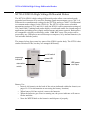
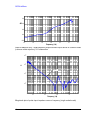
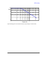
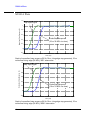
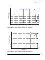
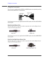
N2791A 25 MHz and N2891A 70 MHz High-Voltage Differential Probes User’s Guide For Safety, Regulatory, and publishing information, see the pages at the back of this book. © Copyright Agilent Technologies 2009 All Rights Reserved. Contents Inspecting the Probe 3 Cleaning the Probe 3 Handling the Probe 3 N2791A/N2891A High-Voltage Differential Probes 4 Contents and Accessory Kits 5 Characteristics and Specifications 7 Safety Information 9 Using the N2791A High-Voltage Differential Probe 10 Using the N2891A High-Voltage Differential Probe 11 N2791A Plots 12 N2891A Plots 16 Using the Accessories 20 2 Inspecting the Probe Inspecting the Probe o Inspect the shipping container for damage. Keep the damaged shipping container or cushioning material until the contents of the shipment have been checked for completeness and the probe has been checked mechanically and electrically. o Check the accessories. • If the contents are incomplete or damaged, notify your Agilent Technologies Sales Office. o Inspect the instrument. • If there is mechanical damage or defect, or if the probe does not operate properly or pass calibration tests, notify your Agilent Technologies Sales Office. • If the shipping container is damaged, or the cushioning materials show signs of stress, notify the carrier as well as your Agilent Technologies Sales Office. Keep the shipping materials for the carrier’s inspection. The Agilent Technologies office will arrange for repair or replacement at Agilent Technologies’ option without waiting for claim settlement. Cleaning the Probe Disconnect the probe and clean it with a soft cloth. Make sure the probe is completely dry before reconnecting it to an oscilloscope. Avoid using abrasive cleaners and chemicals containing benzene or similar solvents. Handling the Probe ! Handle the probe with care and refer to the safety notices at the back of this manual and on page 9. Note that the probe cable is a sensitive part of the probe and, therefore, you should be careful not to damage it through excessive bending or pulling. You should also avoid any mechanical shocks to this product in order to guarantee accurate performance and protection. 3 N2791A/N2891A High-Voltage Differential Probes N2791A/N2891A High-Voltage Differential Probes The N2791A/N2891A high-voltage differential probes allow conventional earthgrounded oscilloscopes to be used for floating signal measurements (up to 700 V of differential or common mode voltage for the N2791A and up to 7000 V of differential or common mode voltage for the N2891A). The N2791A offers users selectable attenuation settings of 10:1 and 100:1 while the N2891A offers attenuation settings of 100:1 and 1000:1, making both probes highly versatile and usable for a broad range of applications including power supply measurements and motor controls. Both probes are compatible with any oscilloscope with a 1 MW BNC input. The probes can be powered by any USB port on an oscilloscope or computer, or by internal batteries (4x AA included with the probe). The images below show some key parts of the N2891A probe body. The N2791A has similar switches/LEDs, but they are arranged differently. on/off switch overrange indicator attenuation switch power LED indicator USB power cord input Battery Use • Insert 4 AA batteries in the back of the unit as indicated within the chassis (see pages 10-11 for information on accessing the battery location) • When battery life has expired, remove the batteries • When the batteries gets close to running out, the power indicator will start to flicker and dim • Note the WEEE label on the batteries and dispose of properly 4 Contents and Accessory Kits Contents and Accessory Kits The following table lists the parts included with the N2791A high-voltage differential probe. Part N2791A 25 MHz differential probe Safety Hook, Red Safety Hook, Black Alligator Clip, Red Alligator Clip, Black USB Power Cord (2 m) AA Battery User’s Guide Quantity 1 1 1 1 1 1 4 1 For N2791A replacement accessories, you can order the N2791-68700 Differential Probe Accessory Kit. It includes: Part Safety Hook, Red Safety Hook, Black Alligator Clip, Red Alligator Clip, Black USB Power Cord (2 m) Quantity 1 1 1 1 1 T 5 Contents and Accessory Kits The following table lists the parts included with the N2891A high-voltage differential probe. Part N2891A 70 MHz differential probe Safety Hook, Red Safety Hook, Black High Voltage Alligator Clip, Red High Voltage Alligator Clip, Black USB Power Cord (2 m) AA Battery User’s Guide Quantity 1 1 1 1 1 1 4 1 For N2891A replacement accessories, you can order the N2891-68700 Differential Probe Accessory Kit. It includes: Part Safety Hook, Red Safety Hook, Black High Voltage Alligator Clip, Red High Voltage Alligator Clip, Black USB Power Cord (2 m) 6 Quantity 1 1 1 1 1 Characteristics and Specifications Characteristics and Specifications Characteristics and specifications for the N2791A and N2891A high-voltage differential probes are shown below. The probe / oscilloscope should be warmed up for at least 20 minutes before any testing and the environmental conditions should not exceed the probe’s specified limits. Electrical Characteristics N2791A Bandwidth (-3 dB) >25 MHz (driving 1 MW oscilloscope input) Attenuation ratio 10:1, 100:1 (switchable) Probe Risetime (10%-90%) 14 ns Absolute Maximum Rated 1000 Vrms CAT II Input Voltage (each side to ground) Maximum Differential Input \70 V at 10:1 attenuation \700 V at 100:1 attenuation Voltage (DC + AC Peak) Maximum Common Mode \70 V at 10:1 attenuation \700 V at 100:1 attenuation Input Voltage Input Impedance Output Voltage Swing Offset (typical) CMRR (typical) Power Requirements Battery Life Battery/Power Cord N2891A 70 MHz (driving 1 MW oscilloscope input) 100:1, 1000:1 (switchable) 5 ns 5000 Vrms CAT I \700 V at 100:1 attenuation \7000 V at 1000:1 attenuation \7000 V at 10:1 attenuation \7000 V at 1000:1 attenuation 4 MW, 10 pF (each side to ground) 50 MW, 7 pF (each side to ground) 8 MW, 8 pF (between inputs) 100 MW, 5 pF (between inputs) \7 V (driving 1 MW oscilloscope \7 V (driving 1 MW oscilloscope input) input) \7.5 mV \5 mV -80 dB at 60 Hz, -40 dB at 1 MHz -80 dB at 50 Hz, -60 dB at 20 kHz 4 AA batteries or USB power adapter 4 AA batteries or USB power adapter (5 V/200 mA, 9 V/120 mA) (5 V/200 mA, 9 V/120 mA) 15 hours (alkaline battery) 11.5 hours (alkaline battery) The supplied voltage must be less The supplied voltage must be less than 12 V and greater than 4.4 V or than 12 V and greater than 4.4 V or else the probe could be damaged else the probe could be damaged - all are typical 7 Characteristics and Specifications Mechanical Characteristics Weight (probe only) BNC Cable Length Length of Input Leads Dimensions (L x W x H) N2791A 400 g (probe and PVC jacket) 95 cm (37 inches) 45 cm (18 inches) 170 mm x 63 mm x 21 mm (6.7 inches x 2.5 inches x 0.83 inches) N2891A 500 g 90 cm (35 inches) 60 cm (24inches) 202 mm x 83 mm x 38 mm (8.0 inches x 3.3 inches x 1.5 inches) Environmental Specifications (same for both N2791A and N2891A) Temperature Altitude Humidity Pollution Degree Operating: -10 °C to +40 °C Nonoperating: -30 °C to +70 °C Operating: 3,000 m Nonoperating: 15,300 m Operating: 25 - 85% room humidity Nonoperating: 25 - 85% room humidity Pollution Degree 2 Safety Specifications CEI/IEC 61010-031 CAT II (N2791A) CEI/IEC 61010-031 CAT I (N2891A) 8 Safety Information Safety Information Warning ! To avoid personal injury and to prevent fire or damage to this product or products connected to it, review and comply with the following safety precautions. Be aware that if you use this probe assembly in a manner not specified, the protection this product provides may be impaired. Observe Maximum Working Voltage To avoid injury, do not use the N2791A probe above 1000 Vrms CAT II (both 10:1 and 100:1 attenuation settings) between each input lead and earth or between the two input leads. Do not use the N2891A probe above 5000 Vrms CAT I (1000:1 attenuation) or 500 Vrms CAT I (100:1 attenuation) between the two input leads. Do not use the N2891A probe above 5000 Vrms CAT I (both 100:1 and 1000:1 attenuation settings) between each input lead and earth. Must be Grounded Before making connections to the input leads of this probe, ensure that the output BNC connector is attached to the BNC channel input of the oscilloscope and the oscilloscope is properly grounded. Use Fused Test Prods if Necessary If this probe is intended to be used with circuits of installation category II, it should incorporate the fused test prods. Do Not Operate Without Covers To avoid electrical shock or fire hazard, do not operate this probe with the covers removed. Do Not Operate in Wet / Damp Conditions To avoid electrical shock, do not operate this probe in wet or damp conditions. Do Not Operate in an Explosive Atmosphere To avoid injury or fire hazard, do not operate this probe in an explosive atmosphere. Avoid Exposed Circuit To avoid injury, remove jewelry such as rings, watches, and other metallic objects. Do not touch exposed connections and components when power is present. Use Proper Power Source To ensure this probe functions well, use four AA batteries or the supplied USB power cord. For Indoor Use Only Only use this probe indoors. 9 Using the N2791A High-Voltage Differential Probe Do Not Operate With Suspected Failures If you suspect there is damage to this probe, have it inspected by a qualified service personnel. Using the N2791A High-Voltage Differential Probe • To use this probe, first insert the four AA batteries into the probe or connect the USB power cord to the probe and a USB port (see page 4 to see where the USB power cord input is located on the probe). To replace batteries, first slip off the cover Then slide the battery cover off on the rear of the probe • Then connect the BNC output connector to the channel input of the oscilloscope. The oscilloscope must have a ground referenced. • Select the proper attenuation ratio (10:1 or 100:1) on the probe via the attenuation switch and specify the attenuation and probe configuration on your oscilloscope. TIP: When measuring signals below 70 V, switch the attenuation ratio to 10:1 in order to obtain a higher resolution signal with less noise. Otherwise set the attenuation ratio to 100:1. 10 Using the N2891A High-Voltage Differential Probe ! ! • Using the appropriate probe accessories, connect the inputs to the circuit under test. To protect against electrical shock, use only the accessories supplied with this probe or in the accessory kit. This probe is to carry out differential measurements between two points on the circuit under test. This probe is not for electrically insulating the circuit under test and the measuring instrument. Using the N2891A High-Voltage Differential Probe • To use this probe, first insert the four AA batteries into the probe or connect the USB power cord to the probe and a USB port (see page 4 to see where the USB power cord input is located on the probe). Slide the battery cover off the rear of the probe body • Then connect the BNC output connector to the channel input of the oscilloscope. The oscilloscope must have a ground referenced. • Select the proper attenuation ratio (100:1 or 1000:1) on the probe via the attenuation switch (see the picture on page 4) and specify the attenuation and probe configuration on your oscilloscope. TIP: When measuring signals below 700 V, switch the attenuation ratio to 100:1 in order to obtain a higher resolution signal with less noise. Otherwise set the attenuation ratio to 1000:1. ! ! • Using the appropriate probe accessories, connect the inputs to the circuit under test. To protect against electrical shock, use only the accessories supplied with this probe or in the accessory kit. This probe is to carry out differential measurements between two points on the circuit under test. This probe is not for electrically insulating the circuit under test and the measuring instrument. 11 N2791A Plots N2791A Plots 1.2 1 0.8 Step Input Signal Volts 0.6 Measured Step Response (17 ns 10-90% rise time) 0.4 0.2 0 -0.2 -100 -50 0 50 100 150 Time (ns) Graph of normalized step response (50, 16.5 ns rising edge step generator), 17 ns normalized rising edge (10-90%), 10:1 attenuation 1.2 1 0.8 Step Input Signal Volts 0.6 Measured Step Response (17 ns 10-90% rise time) 0.4 0.2 0 -0.2 -100 0 100 200 Time (ns) 300 400 500 Graph of normalized step response (50, 17 ns rising edge step generator), 17 ns normalized rising edge (10-90%), 100:1 attenuation 12 N2791A Plots 5 Vout/Vin dB 0 -5 -10 Vin -15 -20 Vout 0 1 10 10 Frequency (MHz) Graph of dB(Vin), dB(Vout) + 20dB, and dB(Vout/Vin) + 20dB frequency response, 10:1 attenuation 5 dB Vout/Vin 2.5 0 -2.5 Vout -5 -7.5 -10 Vin 0 1 10 10 Frequency (MHz) Graph of dB(Vin), dB(Vout) + 40dB, and dB(Vout/Vin) + 40dB frequency response, 100:1 attenuation 13 N2791A Plots -20 dB-40 -60 -80 -100 2 10 3 10 4 5 10 6 10 10 7 10 8 10 Frequency (Hz) Graph of dB(Vout/Vin) + 20dB frequency response when inputs driven in common mode (common mode rejection), 10:1 attenuation 5 10 4 10 22 pF 3 10 2 10 6 10 7 10 8 10 9 10 Frequency (Hz) Magnitude plot of probe input impedance versus frequency (single-ended mode) 14 N2791A Plots 1100 900 Vrms 700 500 300 100 6 10 7 10 Frequency (Hz) Typical derating plot of the absolute maximum input voltage in common mode 15 N2891A Plots N2891A Plots 1.2 Step Input Signal Normalized Step Response (V) 1 0.8 0.6 Probe Step Response (10 ns 10-90% rise time) 0.4 0.2 0 -0.2 -20 0 20 40 Time (nS) 60 80 100 Graph of normalized step response (50 W, 10 ns rising edge step generator), 10 ns normalized rising edge (10-90%), 100:1 attenuation 1.2 Step Input Signal Normalized Step Response (V) 1 0.8 0.6 0.4 Probe Step Response (10 ns 10-90% rise time) 0.2 0 -0.2 -20 0 20 40 Time (nS) 60 80 100 Graph of normalized step response (50 W, 10 ns rising edge step generator), 10 ns normalized rising edge (10-90%), 1000:1 attenuation 16 N2891A Plots 5 0 Normalized S21+40dB -5 -10 -15 -20 -25 -30 -35 0 10 2 4 10 10 Frequency Hz 6 8 10 10 Graph of dB (S21) + 40 dB frequency response, 100:1 attenuation 4 2 Normalized S21+60dB 0 -2 -4 -6 -8 -10 -12 -14 -16 0 10 2 10 4 10 Frequency Hz 6 10 8 10 Graph of dB (S21) + 60 dB frequency response, 1000:1 attenuation 17 N2891A Plots -10 -20 -30 CMRR dB -40 -50 -60 -70 -80 -90 2 4 10 6 10 8 10 10 Frequency (Hz) Graph of dB (S21) + 40 dB frequency response when inputs driven in common mode (common mode rejection), 100:1 attenuation 10 10 9 10 Input impedance (Ohms) 8 differential 10 5 pF single-ended 7 10 6 10 7.2 pF 5 10 4 10 3 10 0 10 2 10 4 10 Frequency (Hz) 6 10 8 10 Magnitude plot of probe input impedance versus frequency, single-ended and differential 18 N2891A Plots 10 4 Vrms 10 10 3 2 1 10 5 10 10 6 10 7 10 8 Frequency (Hz) Typical derating plot of the absolute maximum input voltage in common mode Input impedance equivalent circuit diagram 19 Using the Accessories Using the Accessories The accessories supplied with the N2791A and N2891A probes are attached by pushing them onto the probe leads as shown below. probe lead hook or clip The following accessories are supplied with the N2791A probe and with the N2791-68700 Accessory Kit. Safety Hook and Alligator Clips Use the safety hooks to clamp onto smaller components and use the alligator clips to clamp onto thicker gauge devices safety hook alligator clip The following accessories are supplied with the N2891A probe and with the N2891-68700 Accessory Kit. Safety Hook and High-Voltage Alligator Clips Use the safety hooks to clamp onto smaller components and use the alligator clips to clamp onto thicker gauge devices safety hook 20 high-voltage alligator clip Using the Accessories 21