1
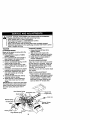
Owner's Manual
I[RAFTSMAW I
17.5 HP
ELECTRIC
START
42" MOWER
6 SPEED TRANSAXLE
LAWN TRACTOR
Model No.
917.271733
•
•
•
•
Safety
Assembly
Operation
Maintenance
• Repair Parts
CAUTION:
Read and follow all Safety
Rules and Instructions before
For answers to your questions
about this product, Call:
operating this equipment.
Sears Craftsman Help Line
5 am - 5 prn, Mon- Sat
1-800-659-5917
Sears, Roebuck and Co., Hoffman Estates, II 60179
Visit our Craftsman website:www.sears.com/craftsman
Maintenance
Warranty
...............................................
2
Safety Rules ......................................... 3
Product Specifications .......................... 6
Assembly .............................................. 8
Operation ............................................ 11
Maintenance Schedule ...................... 17
....................................... 17
Service and Adjustments .................... 21
Storage ............................................... 27
Troubleshooting ................................. 28
Repair Parts ........................................ 32
Parts Ordering ..................... Back Cover
LIMITED "I3NOYEAR WARRANTY ON CRAFTSMAN RIDING EQUIPMENT PARTS
For two (2) years from the date of purchase, if this Craftsman Riding Equipment is
maintained, lubricated and tuned up according to the instructions in the owner's
manual, Sears will repair or replace, free of charge, any parts found to be defective in
material or workmanship. Warranty service is available free of charge by returning your
Craftsman riding equipment to your nearest Sears Service Center. In-home warranty
service is available but a trip charge will apply. This warranty applies only while this
product is in the United States.
This Warranty does not cover:
• Expendable items which become worn during normal use, such as blades, spark
plugs, air cleaners, belts and oil filters.
• Tire replacement or repair caused by punctures from outside objects, such as nails,
thorns, stumps, or glass.
• Repairs necessary because of operator abuse, including but not limited to, damage
caused by towing objects beyond the capability of the riding equipment, impacting
objects that bend the frame or crankshaft, or over speeding the engine.
• Repairs necessary because of operator negligence, including but not limited to,
electrical and mechanical damage caused by improper storage, failure to use the
proper grade and amount of engine oil, failure to keep the deck clear of flammable
debris, or the failure to maintain the equipment according to the instructions contained in the owner's manual.
• Engine (fuel system) cleaning or repairs caused by fuel determined to be contaminated or oxidized (stale). In general, fuel should be used within thirty (30) days of its
purchase date.
• Riding equipment used for commercial or rental purposes. A product is "used for
commercial purpose" if is used for any purpose other than single family household
dwellings or in usage where profit is made.
LIMITED 90 DAY WARRANTY ON BATFrERY
For ninety (90) days from date of purchase, if any battery included with this riding
equipment proves defective in material or workmanship and our testing determines the
battery will not hold a charge, Sears will replace the battery at no charge. Warranty
service is available free of charge by returning your Craftsman dding equipment to
your nearest Sears Service Center. In-home warranty service is available but a trip
charge will apply. This warranty applies only while this product is in the United States.
TO LOCATE THE NEAREST SEARS SERVICE CENTER OR TO SCHEDULE IN-HOME
WARRANTY SERVICE, SIMPLY CONTACT SEARS AT 1-800-4-MY-HOME
This Warranty gives you specific legal rights, and you may also have other rights which
may vary from state to state.
Sears, Roebuck and Co., D/817 WA, Hoffman Estates, IL 60179
IMPORTANT: This cutting machine is capable of amputating hands and feet and
throwing ob ects. Failure to observe the fonowing safety instructions could result in
serious injury or death.
I. GENERAL OPERATION
II, SLOPE OPERATION
• Read, understand, and follow all
Slopes are a major factor related to lossinstructions in the manual and on the
of-control and tipaver accidents, which
machine before starting.
can result in severe injury or death. All
• Only allow responsible adults, who are
slopes require extra caution. If you
familiar with the instructions, to operate
cannot back up the slope or if you feel
the machine.
uneasy on it, do not mow it.
• Clear the area of objects such as rocks, DO:
toys, wire, etc., which could be picked
• Mow up and down slopes, not across.
up and thrown by the blade.
• Remove obstacles such as recks, tree
• Be sure the area is clear of other people
limbs, etc.
before mowing. Stop machine if anyone
Watch for holes, ruts, or bumps.
enters the area.
Uneven terrain could overturn the
• Never carry passengers.
machine. Tall grass can hide obstacles.
• Do not mow in reverse unless absoUse slow speed. Choose a low gear
lutely necessary. Always look down and
so that you will not have to stop or shift
behind before and while backing.
while on the slope.
• Be aware of the mower discharge
Follow the manufacturer's recommendirection and do not point it at anyone.
dations for wheel weights or counterDo not operate the mower without either
weights to improve stability.
the entire grass catcher or the guard in
Use extra care with grass catchers or
place.
other attachments. These can change
• Slow down before turning.
the stabilityof the machine.
• Never leave a running machine unatKeep all movement on the slopes slow
tended. Always turn off blades, set
and gradual. Do not make sudden
parking brake, stop engine, and remove
changes in speed or direction.
keys before dismounting.
Avoid starting or stopping on a slope. If
• Turn off blades when not mowing.
tires lose traction, disengage the
• Stop engine before removing grass
blades and proceed slowly straight
catcher or unclogging chute.
down the slope.
• Mow only in daylight or good artificial
DO NOT:
light.
• Do not operate the machine while under • Do not turn on slopes unless necessary, and then, turn s]owly and graduthe influence of alcohol or drugs.
ally downhill, if possible.
• Watch for traffic when operating near or
• Donotmow near drop-offs, ditches, or
crossing roadways.
embankments. The mower could
• Use extra care when loading or unloadsuddenly turn over if a wheel is over
ing the machine into a trailer or truck.
the edge of a cliff or ditch, or if an edge
• Data indicates that operators, age 60
caves in.
years and above, are involved in a large
• Donotmowonwetgress.
Reduced
percentage of riding mower-related
traction could cause sliding.
injuries. These operators should
• Do not try to stabilize the machine by
evaluate their ability to operate the riding
putting your feet on the ground.
mower safely enough to protect them• Do not use grass catcher on steep
selves and others from sedous injury.
slopes.
• Keep machine free of grass, leaves or
other debds build-upwhich can touch
hot exhaust / engine parts and bum. Do
not allow the mower deck to plow leaves
or other debds which can cause build-up
to occur. Clean any oil or fuel
spillage before operating or stodng the
machine. Allow machine to cool before
storage.
3
IILCHILDREN
Tragic
accidents
canoccuriftheoperator
isnotalerttothepresence
ofchildren.
Children
are often attracted to the
machine and the mowing activity. Never
assume that children will remain where
you last saw them.
• Keep children out of the mowing area
and under the watchful care of another
responsible adult.
• Be alert and turn machine off if children
enter the area.
• Before and when backing, look behind
and down for small children.
• Never carry children. They may fall off
and be seriously injured or interfere
with safe machine operation.
• Never allow children to operate the
machine.
• Use extra care when approaching blind
corners, shrubs, trees, or other objects
that may obscure vision.
IV. SERVICE
• Use extra care in handling gasoline
and other fuels. They are flammable
and vapors are explosive.
-Use only an approved container.
-Never remove gas cap or add fuel
with the engine running. Allow
engine to cool before refueling. Do
not smoke.
-Never refuel the machine indoors.
- Never store the machine or fuel
container inside where there is an
open flame, such as a water heater.
• Be sure the area is clear of other
people before mowing. Stop machine if
anyone enters the area.
• Never carry passengers or children
even with the blades off.
• Do not mow in reverse unless absolutely necessary. Always look down
and behind before and while backing.
• Never carry children. They may fall off
and be sedously injured or interfere
with safe machine operation.
• Keep children out of the mowing area
and under the watchful care of another
responsible adult.
• Never run a machine inside a closed
area.
• Keep nuts and bolts, especially blade
attachment bolts, tight and keep
equipment in good condition.
• Never tamper with safety devices.
Check their proper operation regulady.
• Keep machine free of grass, leaves, or
other debris build-up. Clean oil or fuel
spillage. Allow machine to cool before
storing.
• Stop and inspect the equipment if you
strike an object. Repair, if necessary,
before restarting.
• Never make adjustments or repairs
with the engine running.
• Grass catcher components are subject
to wear, damage, and deterioration,
which could expose moving parts or
allow objects to be thrown. Frequently
check components and replace with
manufacturer's recommended parts,
when necessary.
• Mower blades are sharp and can cut.
Wrap the blade(s) or wear gloves, and
use extra caution when servicing them.
• Check brake operation frequently.
Adjust and service as required.
• Be alert and turn machine oft if children
enter the area.
• Before and when backing, look behind
and down for small children.
• Mow up and down slopes (15° Max),
not across.
• Remove obstactes such as rocks, tree
limbs, etc.
• Watch for holes, ruts, or bumps.
Uneven terrain could overturn the
machine. Tall grass can hide obstacles.
•
Use slow speed. Choose a low gear so
that you will not have to stop or shift
while on the slope.
• Avoid starting or stopping on a slope. If
tires lose traction, disengage the
blades and proceed slowly straight
down the slope.
• If machine stops while going uphill,
disengage blades, shift into reverse
and back down slowly.
• Do not turn on slopes unless necessary, and then, turn slowly and gradually downhill, if possible.
_i CAUTION: Tow only the attachments
that are recommended by and comply
with specifications of the manufacturer of
your tractor. Use common sense when
towing. Operate only at the lowest
possible speed when on a slope. Too
heavy of a load, while on a slope, is
dangerous. Tires can lose traction with
the ground and cause you to lose control
of your tractor.
_ILWARNING: Engine exhaust, some of
its constituents, and certain vehicle
components contain or emit chemicals
known to the State of California to cause
cancer and birth defects or other reproductive harm.
_ILook for this symbol to point out
important safety precautions. It means
CAUTION!!I BECOMEALERT!!! YOUR
SAFETY IS INVOLVED.
_IWARNING:
Battery posts, terminals
and related accessories contain lead and
lead compounds, chemicals known to the
State of California to cause cancer and
birth defects or other reproductive harm.
Wash hands after handling.
A0i, CAUTION: In order to prevent
accidental starting when setting up,
transporting, adjusting or making repairs,
always disconnect spark plug wire and
place wire where it cannot contact spark
plug.
_l CAUTION: Do not coast down a hill
in neutral, you may lose control of the
tractor.
5
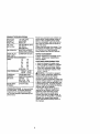
PRODUCT
SPECIFICATIONS
GASOLINE
CAPACITY
ANDTYPE:
1.25 GALLONS
UNLEADED
REGULAR
OILTYPE
API-SF-SJ):
SAE 30 (ABOVE 32°F
SAE 5W-3Q
(BELOW 32°F)
W/FILTER: 3.5 PINTS
W/OFILTER: 3.0 PINTS
CHAMPION RC12YC
OIL CAPACITY:
Should you experience any problem you
cannot easily remedy, please contact a
Sears or other qualified service center.
We have competent, well-trainod techniclans and the proper tools to service or
repair this tractor.
Please read and retain this manual. The
instructions will enable you to assemble
and maintain your tractor propedy.
Always observe the "SAFETY RULES".
SPARK PLUG:
GAP: .030")
GROUND SPEEDFORWARD:
(MPH):
1sT
1.2
2 N°
1.5
3_
2,4
4 TM
3.5
5 TM
4.8
6 TM
5.3
REPAIR AGREEMENT
A Repair Agreement is available on this
product. Contact your nearest Sears
store for details.
CUSTOMER RESPONSIBILITIES
• Read and observe the safety rules.
• Follow a regular schedule in maintaining, caring for and using your tractor.
• Follow the instructions under "Maintenance" and "Storage" sections of this
owner's manual.
IRE PRESSURE: REVERSE:
FRONT; 1.5
14 PSI
REAR: 10PSI
_,HARGING
3AMPS BATI'E RY
3YSTEM:
5 AMPS HEADLIGHTS
3A'N-ERY:
AMP/HR:
25
MIN. CCA: 190
CASE SIZE: Ut R
]LADE BOLT
27-35 FT. LBS.
FORQUE:
_WARNING:
This tractor is equipped
with an internal combustion engine and
should not be used on or near any
unimproved forest-covered, brushcovered or grass-covered land unless the
engine's exhaust system is equipped with
a spark arrester meeting applicable local
or state laws (if any). If a spark arrester is
used, it should be maintained in effective
working order by the operator.
In the state of California the above is
required by law (Section 4442 of the
California Public Resources Code).
Other states may have similar laws.
Federat laws apply on federal lands. A
spark arrester for the muffler is available
through your nearest Sears service
center (See REPAIR PARTS section of
this manual),
CONGRATULATIONS on your purchase
of a new tractor, It has been designed,
engineered and manufactured to give
you the best possible dependability and
performance.
6
Steering Wheel
Steering
WheelInsert
(1) Large Flat Washer
I_(1)
Hex Bolt
_
(1) Lock
3/8-16 x 1
_
washer 3/8
(1) Hex Bolt
5/16-18 x 1-1/4
(1)
Locknut
5/16-18
Steering
Boot
J]_
Steering
Extension
Shaft
Steering
Wheel Adapter
Seat
(_Washer
17/32 x 1-3/16 x 12
Gauge
_(1)
Knob
For Future Use
Keys
Slope Sheet
Video Cassette
Your new tractor has been assembled at the factory with exception of those parts left
unassembled for shipping purposes. To ensure safe and proper operation of your
tractor all parts and hardware you assemble must be tightened securely. Use the
correct tools as necessary to insure proper tightness.
TOOLS REQUIRED FOR ASSEMBLY
A socket wrench set will make assembly
easier. Standard wrench sizes you need
are listed below.
(1) 9/16" wrench
(1) Pliers
(2) 1/2"wrench
(1) Utility knife
(1) "lire pressure gauge
When right or left hand is mentioned in
this manual, it means, from your point of
view, when you are in the operating
position (seated behind the steering
wheel).
TO REMOVE TRACTOR FROM
CARTON
UNPACK CARTON
1. Remove all accessible loose parts
and parts canons from canon.
2. Cut, from top to bottom, along lines on
all four corners of canon, and lay
panels flat.
3. Check for any additional loose parts
or canons and remove.
BEFORE REMOVING TRACTOR
FROM SKID
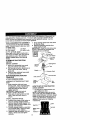
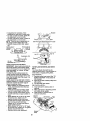
A'I-rACH STEERING WHEEL
ASSEMBLE EXTENSION SHAFT AND
BOOT
1. Slide extension shaft onto lower
steering shaft. Align mounting holes
in extension and lower shafts and
install 5/16 hex bolt and Iocknut.
Tighten securely.
IMPORTANT; Tighten bolt and nut
securely to 18-22 ft. Ibs torque.
2. Place tabs of steering boot over tab
slots in dash and push down to
secure.
INSTALL STEERING WHEEL
3. Position front wheels of the tractor so
they are pointing straight forward.
4. Remove steering wheel adapter from
steedng wheel and slide adapter onto
steering shaft extension.
5. Position steering wheel so cross bars
are horizontal (left to right) and slide
inside boot and onto adapter.
6. Assemble large flat washer, 3/8 lock
washer, 3/8 bex bolt and tighten
securely.
7. Snap steering wheel insert into center
of steedng wheel.
8. Remove protective materials from
tractor hood and gdll.
IMPORTANT; Check for and remove any
staples in skid that may puncture tires
where tractor is to roll off skid.
3/8 Hex Bolt
3/8 LockWasher
at
A_d_ei_S_rln
g Boot
i Hex Bolt
5116 Lock,nut
HOW TO SET UP YOUR TRACTOR
CHECK BA'rrERY
1. Lift seat pan to raised position and
open battery box door.
NOTE: If this battery is put into service
after month and year indicated on label
(label located between terminals) charge
battery for minimum of one hour at 6-10
amps. (See "BA3-rERY" in Maintenance
section of this manual for charging
instructions).
Label
Batter
Door
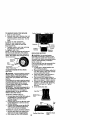
INSTALL SEAT
Adjust seat before tightening adjustment
knob.
I. Remove adjustment knob and fiat
washer securing seat to cardboard
packing and set aside for assembly of
seat to tractor.
2. Pivot seat upward and remove from
the cardboard packing. Remove the
cardboard packing and discard.
3. Place seat on seat pan so head of
shoulder bolt is positioned over large
slotted hole in pan.
4. Push down on seat to engage
shoulder bolt in slot and pull seat
towards rear of tractor.
5. Pivot seat and pan forward and
assere_le adjustment knob and flat
washer loosely. Do not tighten.
6. Lower seat into operating position and
sit in seat,
7. Slide seat until a comfortable position
is reached which allows you to press
clutch/brake pedal all the way down.
8. Get off seat without moving its
adjusted position.
9, Raise seat and tighten adjustment
knob securely.
Seat
NOTE: You may now roll or drive your
tractor off the skid. Follow the appropriate
instructionbelow to remove the tractor
from the skid.
TO ROLL TRACTOR OFF SKID (See
Operation section for location and
function of controls)
1. Press lift lever plunger and raise
attachment lift lever to its highest
position.
2. Release parking brake by depressing
clutch/brake pedal.
3. Place gearshift lever in neutral (N)
position.
4. Roll tractor forward off skid.
5. Remove banding holding denector
shield up against tractor.
TO DRIVE TRACTOR OFF SKID (See
Operation section for location and
function of controls)
,_ILWARNING: Before starting read,
understand and follow all nstructons n
the Operation section of this manual. Be
sure tractor is in a wen-ventilated area.
Be sure the area in front of tractor is clear
of other people and ob ects.
1. Be sure all the above assembly steps
have been completed.
2. Check engine oil level and fill fuel
tank with gasoline.
3. Sit on seat in operating position,
depress clutch/brake pedal and set
the parking brake.
4. Place gear shift lever in neutral (N)
position.
5. Press tilt lever plunger and raise
attachment lift lever to its highest
position.
6. S_art the engine. After engine has
started, move throttle control to idle
position.
7. Depress clutch/brake pedal into fu_l
"BRAKE" position and hold. Move
gearshift lever to 1st gear.
8. Slowly release clutctVbrake pedal and
slowly drive tractor off skid.
9. Apply brake to stop tractor, set parking
brake and place gearshift lever in
neutral position.
10.Turn ignition key to "OFF" position.
Continue with the instructions that follow.
CHECK TIRE PRESSURE
The tires on your tractor were overinflated
at the factory for shipping purposes.
Correct tire pressure is important for best
cutting performance.
• Reduce tire pressure to PSI shown in
"PRODUCT SPECIFICATIONS" section
of this manual.
CHECK
DECKLEVELNESS
Forbestcutting
results,
mower
housing
should
beproperly leveled, See "TO
LEVEL MOWER HOUSING" in the
Service and Adjustments section of this
manual.
CHECK FOR PROPER POSITION OF
ALL BELTS
See the figures that are shown for
replacing motion and mower b]ade drive
belts in the Service and Adjustments
section of this manual. Verify that the
belts are routed COrrectly,
CHECK BRAKE SYSTEM
After you learn how to operate your
tractor, check to see that the brake is
properly adjusted. See "TO ADJUST
BRAKE" in the Service and Adjustments
section of this manual.
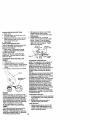
INSTALL MULCHER PLATE
(If previously removed)
1. Raise and hold deflector shield in
upright position.
2. Place front of mulcher plate over front
of mower deck opening and slide into
place, as shown.
3. Hook front latch into hole on front of
mower deck.
4. Hook rear latch into hole on back of
mower deck.
_IkCAUTION: Do not remove deflector
shield from mower. Raise and hold shield
when attaching mulcher plate and allow it
to rest on plate while in operation.
Mulcher
Plate
,Y CHECKLIST
Before you operate and enjoy your new
tractor, we wish to assure that you receive
the best performance and satisfaction
from this Quality Product.
Please review the following checklist:
,/All assembly instructions have been
completed.
,/No remaining loose parts in carton.
,/Battery is properly prepared and
charged. (Minimum 1 hour at 6 amps).
/ Seat is adjusted comfortably and
tightened securely.
/ All tires are properly inflated. (For
shipping purposes, the tires were
overinflated at the factory).
,/Be sure mower deck is properly Leveled
side-to-side/front-to-rear for best cutting
results. (Tires must be properly inflated
for leveling).
/ Check mower and drive belts. Be sure
they are routed properly around pulleys
and inside all belt keepers.
,/Check wiring. See that all connections
are still secure and wires are properly
clamped.
While learning how to use your tractor,
pay extra attention to the following
important items:
#" Engine oil is at proper level.
,/ Fuel tank is filled with fresh, clean,
regular unleaded gasoline.
#' Become familiar with all controls - their
location and function. Operate them
before you start the engine.
,/Be sure brake system is in safe
operating condition.
Shield
Latch
Hooks
TO CONVERT TO BAGGING OR
DISCHARGING
Simply remove mulcher plate and store in
a safe place, Your mower is now ready for
discharging or installation of optional
grass catcher accessory.
NOTE: It is not necessary to change
blades. The mulcher blades are designed for discharging and bagging also.
10
These symbols may appear on your tractor or in literature supplied with the product.
Learn and understand their meaning.
A,
BATTERY
CAUTION OR
WARNING
ENGINE ON
ENGINE OFF
FUEL
CHOKE
REVERSE
OIL PRESSURE
MOWER
HEIGHT
_r_RN
ATrACHMENT
CLUTCH ENGAGED
REVERSE
O_(_)
IGNmON
NEUTRAL
ATTACHMENT
CLUTCH
FORWARD
FAST
LIGHTS ON
!
OVER TEMP
LIGHT
PARKING BRAKE
LOCKED
H
L
HIGH
LOW
KEEP AREA CLEAR
DISENGAGED
SLOW
(SEE SAFETY
UNLOCKED
MOWERLI_
PARKING
SLOPE
RULES
BRAKE
HAZARDS
SECTION)
FREE WHEEL
DANGER.
KEEP HANDS
AND FEET
AWAY
(Automatic
11
Models o_y)
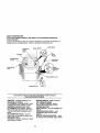
KNOWYOUR TRACTOR
READ THIS OWNER'S MANUAL AND SAFETY RULES BEFORE OPERATING
YOUR TRACTOR
Compare the illustrations with your tractor to familiarize yourself with the locations of
various controls and adjustments. Save this manual for future reference.
Light Switch
Attachment
Clutch
Ammeter
Ignition Switch
......
UR
Lever
Plunger
-.
Throttle/Choke
Control
Attachment
Lift Lever
Clutch/Brake
Pedal
Height
Adjustment
Indicator
Parking Brake Lever
Gearshi_
Lever
Our tractors conform to the safety standards of the American
National Standards Institute.
AMMETER - Indicates charging (+) or
discharging (-) of battery.
AI-FACHMENT CLUTCH LEVER - Used
to engage the mower blades, or other
attachments mounted to your tractor.
ATFACHMENT LIFT LEVER - Used to
raise, lower, and adjust the mower deck
or other attachments mounted to your
tractor.
CLUTCH/BRAKE PEDAL - Used for
declutching and braking the tractor and
startingthe engine.
GEARSHIFT LEVER - Selects the speed
and direction of tractor.
IGNITION SWITCH - Used for starting
and stopping the engine.
LIFT LEVER PLUNGER - Used to
release attachment lift lever when
changing its position.
LIGHT SWITCH - Turns the headlights on
and off.
PARKING BRAKE LEVER - Locks
clutch/brake pedal into the brake
position.
THRO'I-I'LE/CHOKE CONTROL- Used
for starting and controlling engine speed.
12
The operation of any tractor can result in foreign objects thrown into
the eyes, which can result in severe eye damage. Always wear safety
glasses or eye shields while operating your tractor or performing any
ad ustments or repairs. We recommend a wide vision safety mask over
spectac es or standard safety g asses.
HOW TO USE YOUR TRACTOR
TO SET PARKING BRAKE
Your tractor is equipped with an operator
presence sensing switch. When engine
is running, any attempt by the operator to
leave the seat without first setting the
parking brake will shut oft the engine.
1. Depress clutch/brake pedal into fun
"BRAKE" position and hold.
2. Place parking brake lever in "ENGAGED" position and release
pressure from clutch/brake pedal.
Pedal should remain in "BRAKE"
position. Make sure parking brake will
hold tractor secure.
AttachmentClutch Lever
=Engaged"_
Throttle
C_o_
'_
,
IgnitionKey
/
Pos_Uon
Parking Brake
_
._'_._\
\V j"Engaged"
Clutch/
_,'-\_ 'x__,-:.1
Position
Brake Pedal
"i.......
/
"Disen_g_r
Position
. .or'-...Lever
....
Position
STOPPING
MOWER BLADES • To stop mower blades,move attachment clutch lever to "DISENGAGED"
position.
GROUND DRIVE • To stop ground drive, depress clutch/
brake pedal into full "BRAKE" position.
• Move gearshift lever to neutral (N)
position.
ENGINE • Move throftie control to slow position.
NOTE; Failure to move throttle control to
slow position and allowing engine to idle
before stopping may cause engine to
"backfire".
• Turn ignition key to "OFF" position and
remove key. Always remove key when
leaving tractor to prevent unauthorized
IMPORTANT: Leaving the ignition switch
in any position other than "OFF" will
cause the battery to be discharged,
(dead).
NOTE; Under certain conditions when
tractor is standing idle with the engine
running, hot engine exhaust gases may
cause "browning" of grass. To eliminate
this possibility, always stop engine when
stopping tractor on grass areas.
_hLCAUTION: Always stop tractor
completely, as described above, before
leaving the operator's position; to empty
grass catcher, etc.
TO USE THRO'n'LE CONTROL
Always operate engine at full throttle.
• Operating engine at less than full
throttle reduces the battery charging
rate.
• Full throttle offers the best bagging
and mower performance.
TO MOVE FORWARD AND
BACKWARD
The direction and speed of movement is
controlled by the gearshift lever.
1. Start tractor with clutch/brake pedal
depressed and gearshift lever in
neutral (N) position.
2. Move gearshift lever to desired
position.
3. Slowly release clutch/brake pedal to
start movement.
IMPORTANT: Bring tractor to a complete
stop before shifting or changing gears.
Failure to do so will shorten the useful life
of your transaxle.
TO ADJUST MOWER CU'I-FING HEIGHT
The position of the attachment lift lever
determines the cutting height.
• Grasp lift lever.
• Press plunger with thumb and move
lever to desired position.
The cutting height range is approximately 1-1/2 to 4". The heights are
measured from the ground to the blade
tip with the engine not running. These
heights are approximate and may vary
depending upon soil conditions, height of
grass and types of grass being mowed.
use.
• Never use choke to stopengine.
13
• The average lawn should be cut to
approximately 2-1/2 inches during the
cool season and to over 3 inches
during hot months. For healthier and
better looking lawns, mow often and
after moderate growth.
• For best cutting performance, grass
over 6 inches in height should be
mowed twice. Make the first cut
relatively high; the second to desired
height.
TO ADJUST GAUGE WHEELS
Gauge wheels are properly adjusted
when they are slightly off the ground
when mower is at the desired cutting
height in operating position. Gauge
wheels then keep the deck in proper
position to help prevent scalping in most
terrain conditions.
NOTE: Adjust gauge wheels with tractor
on a flat level surface.
1. Adjust mower to desired cutting height
(See "TO ADJUST MOWER CUFFING
HEIGHT' in the Operation section of
this manual).
2. With mower in desired height of cut
position, gauge wheels should be
assembled so they are slightly off the
ground. Install gauge wheel in
appropriate hole with shoulder bolt, 3/
8 washer, and 3/8-16 Iocknut and
tighten securely.
3. Repeat for opposite side installing
gauge wheel in same adjustment
hole,
Gauge
Wheel
Bracket
3/8-16
Locknut
Shoulder Bolt
Gauge Wheel
TO OPERATE MOWER
Yourtractor is equipped with an operator
presence sensing switch. Any attempt by
the operator to leave the seat with the
engine running and the attachment clutch
engaged will shut oft the engine.
1. Select desired height of cut.
2. Start mower blades by engaging
attachment clutch control.
TO STOP MOWER BLADES disengage attachment clutch control.
,_ CAUTION: Do not operate the mower
without either the entire grass catcher, on
mowers so equipped, or the deflector
shield in place.
Attachment
Clutch Lever
Attachemnt
LeverHigh
Position
Position
Low
Position
Position
Deflector
Shield
TO OPERATE ON HILLS
_, CAUTION: Do not drive up or down
hills with slopes greater than 15° and do
not drive across any slope.
• Choose the slowest speed before
starting up or down hills.
• Avoid stopping or changing speed on
hills.
• If slowing is necessary, move throttle
control lever to slower position.
• If stopping is absolutely necessary,
push clutchlbrake pedal quickly to
brake position and engage parking
brake.
• Move gearshift lever to 1st gear. Be
sure you have allowed room for tractor
to roll slightly as you restart movement.
• To restart movement, slowly release
parking brake and clutch/brake pedal.
• Make all turns slowly.
TO TRANSPORT
• Raise attachment lift to highest position
with attachment lift control.
• When pushing or towing your tractor,
be sure gearshift lever is in neutral (N)
position.
• Do not push or tow tractor at more than
five (5) MPH.
NOTE: To protect hood from damage
when transporting your tractor on a truck
or a trailer, be sure hood is closed and
secured to tractor. Use an appropriate
means of tying hood to tractor (rope, cord,
etc.).
14
TOWING CARTS AND OTHER A'R'ACHMENTS
Tow only the aftachments that are
recommended by and comply with
specificationsof the manufacturer of your
tractor. Use common sense when towing.
Too heavy of a load, while on a slope, is
dangerous. "Srescan lose traction with
the ground and cause you to lose control
of your tractor.
BEFORE STARTING THE ENGINE
CHECK ENGINE OIL LEVEL
The engine in your tractor has been
shipped, from the factory, already filled
with summer weight oil.
1. Check engine oil with tractor on level
ground.
2. Remove oil fill cap/dipstick and wipe
clean, reinsert the dipstick and screw
cap tight, wait for a few seconds,
remove and read oil level. If necessary, add oil until "FULL" mark on
dipstick is reached. Do not overfill.
• For cold weather operation you should
change oil for easier starting (See "OIL
VISCOSITY CHART" in the Maintenance
section of this manual).
• To change engine oil, see the Maintenance section in this manual.
ADD GASOLINE
• Fill fuel tank. Use fresh, clean, regular
unleaded gasoline with a minimum of
87 octane. (Use of leaded gasoline
will increase carbon and lead oxide
deposits end reduce valve life). Do not
mix oil with gasoline. Purchase fuel in
quantities that can be used within 30
days to assure fuel freshness.
IMPORTANT: When operating in
temperatures b_low32°F(0°C), use fresh,
clean winter grade gasoline to help
insure good cold weather starting.
_WARNING:
Expenenca indicates that
alcohol blended fuels (called gasohol or
using ethanol or methanol) can attract
moisture which leads to separation and
formation of acids during storage. Acidic
gas can damage the fuel system of an
engine while in storage. To avoid engine
problems, the fuel system should be
emptied before storage of 30 days or
longer. Drain the gas tank, start the
engine and let it run until the fuel lines
and carburetor are empty.
Use fresh fuel next season. See Storage
Instructions for additional information.
Never use engine or carburetor cleaner
products in the fuel tank or permanent
damage may occur.
_ICAUTION:
Fill to bottom of gas tank
filler neck. Do not overfill. Wipe off any
spilled oil or fuel. Do not store, spill or
use gasoline near an open flame.
TO START ENGINE
When starting the enginefo(the first time or if
the engine has run out of fuel, it will take extra
crenldng time to move fuel from the tank to
the engine.
1. Sit on seat in operating position,
depress clutch/brake pedal and set
parking brake.
2. Place gear shift lever in neutral (N)
position.
3. Move attachment clutch to "DISENGAGED" position.
4. Move throttle control to choke position.
NOTE: Before starting, read the warm and
cold starting procedures below.
5. Insert key into ignition and turn key
clockwise to "START" position and
release key as soon as engine starts.
Do not run starter continuously for
more than fifteen seconds per minute.
If the engine does not start after
several attempts, move throttle control
to fast position, wait a few minutes and
try again. If engine still does not start,
move the throttle control back to the
choke position and retry.
WARM WEATHER STARTING (50° F and
above)
6. When engine starts, move the throttle
control to the fast position.
• The attachments and ground drive can
now be used. If the engine does not
accept the load, restart the engine and
allow it to warm up for one minute
using the choke as described above.
COLD WEATHER STARTING (50 ° F and
below)
6. When engine starts, allow engine to
run with the throttle control in the
choke position until the engine runs
roughly, then move throttle control to
fast position. This may require an
engine warm-up period from several
seconds to several minutes, depending on the temperature.
15
• The attachments can also be used
during the engine warm-up period.
NOTE: If at a high alf_ude (above 3000 feet)
or in cold temperatures (below 32 F) the
carburetor fuel taLCum may need to be
adjusted for best engine performance. See
"TO ADJUST CARBURETOR" in the Service
and Adjustments section of this manual.
MOWING TIPS
• Mower should be properly leveled for
best mowing performance. See "TO
LEVEL MOWER HOUSING" in the
Service and Adjustments section of this
manual.
• The left hand side of mower should be
used for trimming.
• Drive so that clippings are discharged
onto the area that has been cut. Have
the cut area to the dght of the tractor.
This will result in a more even distribution of clippings and more uniform
cutting.
• When mowing large areas, start by
turning to the right so that clippings will
discharge away from shrubs, fences,
driveways, etc. After one or two
rounds, mow in the opposite direction
making left hand turns until finished.
• If grass is extremely tall, it should be
mowed twice to reduce load and
possible fire hazard from dried clippings. Make first cut relatively high; the
second to the desired height.
• Do not mow grass when it is wet. Wet
grass will plug mower and leave
undesirable clumps. Allow grass to dry
before mowing.
• Always operate engine at full throttle
when mowing to assure better mowing
performance and proper discharge of
material. Regulate ground speed by
selecting a low enough gear to give the
mower cutting performance as well as
the quaJityof cut desired.
• When operating attachments, select a
ground speed that will suit the terrain
and give best performance of the
attachment being used.
MULCHING MOWING TIPS
IMPORTANT: For best performance,
keep mower housing free of built-up
grass and trash. Clean after each use.
• The special mulching blade will recut
the grass clippings many times and
reduce them in size so that as they fall
onto the lawn they will disperse into the
grass and not be noticed. Also, the
mulched grass will biodegrade quickly
to provide nutrientsfor the lawn.
Always mulch with your highest engine
(blade) speed as this will provide the
best recurring action of the blades.
• Avoid cutting your lawn when it is wet.
Wet grass tends to form clumps and
interferes with the mulching action.
The best time to mow your lawn is the
early afternoon. At this time the grass
has dried and the newly cut area will
not be exposed to the direct sun.
• For best results, adjust the mower
cutting height so that the mower cuts off
only the top one-third of the grass
blades. For extremely heavy mulching,
reduce your width of cut on each pass
and mow slowly.
• Certain types of grass and grass
conditions may require that an area be
mulched a second time to completely
hide the clippings. When doing a
second cut, mow across or perpendicular to the first cut path.
• Change your cutting pattern from week
to week. Mow north to south one week
then change to east to west the next
week. This will help prevent matting
and graining of the lawn.
Max 1/3"
16
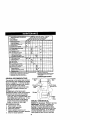
MAINTENANCESCHEDULE
FILL IN OATES
AS YOU
COMPLETE
REGULAR SERVICE
Check Brake Operatk:n
Check Tire Pressure
T
f
Intedock
SyslemsPmserce and
Check
Operalor
, R CileCklorLooseFaste_rs
A
ShaCen/Repla_aMowerBade=
C / Lul_catlon Cha.
I O[ ChedclBatterf
Leve_
Check Transax]e Cooing
Adjust Blade B_(sl Tension
Adler _
c_
D_e B_(S) Tansu_
ShOneoit_
If
Change Engine Oil
E
Clean Air Rtler
N
Clean Air _re_
G
InSpect Mun_er/Spark Arrester
I
RePlaCe Oil Filter (If equipped)
N
Clean En_ne Cocking Fins
Replace Spark Ftug
ReplaCe Air Fltlet Paper Cadr;dge
Replace Fue_F_er
GENERAL RECOMMENDATIONS
The warranty on thistractor does not cover
items that have been subjectedto operator
abuse or negligence. To receive full value
from the warranty,operator must maintain
tractoras instructedin this manual.
Some adjustments will need to be made
periodicallyto properly maintain your
tractor.
All adjustments in the Service and
Adjustments section of this manual should
be checked at least once each season.
• Once a year you should replace the
spark plug, clean or replace air filter, and
check blades and belts for wear. A new
spark plug and clean air filter assure
proper air-fuel mixture and help your
engine run better and last longer.
BEFORE EACH USE
1. Check engine oil level.
2. Check brake operation.
3. Check tire pressure,
4. Check operator presence and
interlock systems for proper operation,
5. Check for loose fasteners,
- _ Spindle
Zerk
Zerk
_Front Wheel
Bearing
Zerk
Bearing Zerk
I
'_
I
(_Gear-
_ . - ....
=
_ _ shift
Pivots
• SAE 30 or 10w30 MOTOR OiL
_GENERAL PURPOSE GREASE
_REFER TO Maintenance "ENGINE" SECTION
IMPORTANT: Do not oil or grease the
_ivot points which have special nylon
earings. Vtscous lubricants will attract
dust and dirt that will shorten the life of the
self-lubricating bearings. If you feel they
must be lubricated, use only a dry, powdered graphite type lubricant sparingly.
17
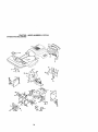
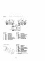
TRACTOR
4. Reassemble hex bolt, lock washer
and flat washer in exact order as
Always observe safety rules when pershown.
forming any maintenance.
5. Tighten bolt securely (27-35 Ft. Lbs.
BRAKE OPERATION
torque).
If tractor requires more than six (6) feet
IMPORTANT: Blade bolt is grade 8 heat
stopping distance at high speed in highest treated.
gear, then brake must be adjusted. (See
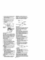
Mandrel Assembly
Trailing Edge Up
"TO ADJUST BRAKE" in the Service and
Blade
Center
Adjustments section of this manual).
t
Hole
TIRES
• Maintain proper air pressure in all tires
Flat Washer.
(See "PRODUCT SPECIFICATIONS"
LockWashe
section of this manual).
• Keep tires free of gasoline, oil, or insect
control chemicals which can harm
_---- Hex Bolt
rubber.
*A Grade 8 heattreatedboltcan be identified
bysix lineson the bolthead.
• Avoid stumps, stones, deep ruts, sharp
objects and other hazards that may
TO SHARPEN BLADE
cause tire damage.
NOTE: We do not recommend sharpenNOTE= To seal tire punctures and prevent
flat tires due to slow leaks, tire sealant may ing blade - but if you do, be sure the blade
is balanced.
be purchased from your local parts dealer.
Care should be taken to keep the blade
Tire sealant also prevents tire dry rot and
balanced. An unbalanced blade will
corrosion.
cause excessive vibration and eventual
OPERATOR PRESENCE SYSTEM
damage to mower and engine.
Be sure operator presence and interlock
• The blade can be sharpened with a file
systems are working properly. If your
or on a grinding wheel. Do not attempt
tractor does not function as described,
to sharpen while on the mower.
repair the problem immediately.
• To check blade balance, you will need
• The engine should not start unless the
a 5/8" diameter steel bolt, pin, or a cone
brake pedal is fully depressed and
balancer. (When using a cone balattachment clutch control is in the
ancer, follow the instructions supplied
disengaged position.
with balancer.)
• When the engine is running, any attempt NOTE: Do not use a nail for balancing
by the operator to leave the seat without blade. The lobes of the center hole may
first setting the parking brake should
appear to be centered, but are not.
shut off the engine.
• Slide blade on to an unthreaded portion
• When the engine is running and the
of the steel bolt or pin and hold the bolt
attachment clutch is engaged, any
or pin parallel with the ground. If blade
attempt by the operator to leave the seat
is balanced, it should remain in a
should shut off the engine.
horizontal position. If either end of the
• The attachment clutch should never
blade moves downward, sharpen the
operate unless the operator is in the
heavy end until the blade is balanced.
seat.
BLADE CARE
For best results mower blades must be
kept sharp. Replace bent or damaged
blades.
BLADE REMOVAL
Center Hole
1. Raise mower to highest position to
BA'n'ERY
allow access to blades.
2. Remove hex bolt, lock washer and flat
Your tractor has a battery charging system
which is sufficient for normal use. Howwasher securing blade.
ever, periodic charging of the battery with
3. Install new or resharpened blade with
an automotive charger will extend its life.
trailing edge up towards deck as
shown.
• Keep battery and terminals clean.
IMPORTANT: To ensure proper assembly, • Keep battery belts tight.
center hole in blade must align with star
• Keep small vent holes open.
18
on mandrel assembly.
//
•
Check the crankcase oil level before
startingthe engine and after each eight (8)
hours of operation. "tightenoil fill cap/
dipstick securely each time you check the
oil level.
Recharge at 6-10 amperes for 1 hour.
NOTE; The original equipment battery on
your tractor is maintenance free. Do not
attempt to open or remove caps or covers.
Adding or checking level of electrolyte is
not necessary.
TO CLEAN BA'I-FERY AND TERMINALS
Corrosion and dirt on the battery and
terminals can cause the battery to "leak"
power.
1. Open battery box door.
2. Disconnect BLACK battery cable first
then RED battery cable and remove
battery from tractor.
3. Rinse the battery with plain water and
dry.
4. Clean terminals and battery cable
ends with wire brush until bright.
5. Coat terminals with grease or petroleum jelly.
6. Reinstall battery (See "REPLACING
BA'I-I'ERY = in the SERVICE AND
ADJUSTMENTS section of this
manual).
V-BELTS
Check V-belts for deterioration and wear
after 100 hours of operation and replace if
necessary. The belts are not adjustable.
Replace belts if they begin to slip from
TO CHANGE ENGINE OIL
Determine temperature range expected
before oil change. All oil must meet API
service classification SF-SJ.
• Be sure tractor is on level surface.
• Oil will drain more freely when warm.
• Catch oil in a suitable container.
1. Remove oil fill cap/dipstick. Be careful
not to allow dirt to enter the engine
when changing oil
2. Remove cap from end of drain valve
and install the drain tube onto the
fitting.
3. Unlock drain valve by pushing inward
slightly and turning counterclockwise.
4. To open, pull out on the drain valve.
5. After oil has drained completely, close
and lock the drain valve by pushing
inward and turning clockwise until the
pin is in the locked position as shown.
6. Remove the drain tube and replace
the cap onto to the end of the drain
valve.
7. Refill engine with oil through oil fill
dipsticktube. Pour slowly. Do not
overfill. For approximate capacity see
"PRODUCT SPECIFICATIONS"
section of this manual.
8. Use gauge on oil fill cap/dipstick for
checking level. Be sure dipstick cap is
tightened securely for accurate
reading. Keep oil at =FULL" line on
dipstick.
Oil DrainValve
Closed
and
Locked
Position
wear.
TRANSAXLE COOLING
Keep transaxle free from build-up of dirt
and chaff which can restrict cooling.
ENGINE
LUBRICATION
Only use high quality detergent oil rated
with API service classificationSF-SJ.
Select the oil'sSAE viscositygrade
according to your expected operating
temperature.
CLEAN AIR SCREEN
Air screen must be kept free of dirt and
chaff to prevent engine damage from
overheating. Clean with a wire brush or
compressed air to remove dirt and
stubborn dried gum fibers.
ENGINE COOLING FINS
NOTE: Although multi-viscosityoils
(5W30, 10W30 etc.) improve starting in
cold weather, these multi-viscosityoils will
result in increased oil consumption when
used above 32"F. Check your engine oil
level more frequently to avoid possible
engine damage from running low on oil.
Change the oil after every 25 hours of
operationor at least once a year if the
tractoris not used for 25 hoursin one year.
Remove any dust, dirt or oil from engine
cooling tins to prevent engine damage
from overheating.
19
1. Remove
screws
from
blower housing
and lift housing and dipstick tube
assembly off engine.
2. Cover oil fill opening to prevent entry
of dirt.
3. Use compressed air or stiff bristle
brush to thoroughly clean engine
cooling fins.
4. To reassemble, reverse above
procedure.
IMPORTANT: Petroleum solvents, such as
kerosene, are not to be used to c_ean the
cartridge. They may cause deterioration of the
cartridge. Do not oil cartridge. Do not use
pressurized air to clean or dry cartridge.
Foam Pre-Clea_er
\Paper
Cartddge
Scre_Screws
DisPst
imC
_ r_U
be __ugr
k
AIR FILTER
Your engine will not run properly using a
dirty air filter. Clean the foam pre-cleaner
after every 25 hours of operation or every
season. Service paper cartridge every
100 hours of operation or every season,
whichever occurs first.
Service air c]eaner more often under
dusty conditions.
1. Remove knob(s) and cover.
TO SERVICE PRE-CLEANER
2.
3.
4.
5.
Slide foam pre-cleaner off cartridge.
Wash it in liquid detergent and water.
Squeeze it dry in a clean cloth.
Saturate it in engine oil. Wrap it in
clean, absorbent cloth and squeeze to
remove excess oil.
NOTE: If very dirty or damaged, replace
pre-cleaner.
6. Reinstall pre-cleaner over cartridge.
7. Reinstall cover and secure with
knob(s).
TO SERVICE CARTRIDGE
1. Remove cartridge nut.
2. Carefully remove cartridge to prevent
debris from entering carburetor.
Clean base carefully to prevent debris
from entering carburetor.
3. Clean cartridge by tapping gently on
flat surface.
NOTE; If very dirty or damaged, replace
cartddge.
4. Reinstall cartridge, nut, precleaner,
cover and secure with knob(s).
MUFFLER
Inspect and replace corroded muffler and
spark arrester (if equipped) as it could
create a fire hazard and/or damage.
SPARK PLUGS
Replace spark plugs at the beginning of
each mowing season or after every 100
hours of operation, whichever occurs first.
Spark plug type and gap setting are
shown in "PRODUCT SPECIFICATIONS"
section of this manual.
IN-LINE FUEL FILTER
The fuel filter should be replaced once
each season. If fuel filter becomes
clogged, obstructing fuel flow to carburetor, replacement is required.
1. With engine cool, remove filter and
plug fuel line sections.
2. Place new fuel filter in position in fuel
line with arrow pointing towards
carburetor.
3. Be sure there are no fuel line leaks
and clamps are properly positioned,
4. Immediately wipe up any spilled
gasoline.
Clamp
Fuel F_lter--------_.J_/__/
--
CLEANING
• Clean engine, battery, seat, finish, etc.
of all foreign matter.
• Keep finished surfaces and wheels free
of all gasoline, oil, etc.
• Protect painted surfaces with automotive type wax.
We do not recommend using a garden
hose to clean your tractor unless the
electrical system, muffler, air filter and
carburetor are covered to keep water out.
Water in engine can result in a shortened
20engine life.
,_CAUTION:
BEFORE PERFORMING ANY SERVICE OR ADJUSTMENTS:
1. Depress clutch/brake pedal fully and set parking brake.
2. Piece gearshift lever in neutral (N) position.
3. Place attachment clutch in "DISENGAGED" position.
4. Turn ignitionkey =OFF' and remove key.
5, Make sure the blades and all moving parts have completely stopped.
6. Disconnect spark plug wire from spark plug and place wire where it cannot
come in contact with ptug,
TRACTOR
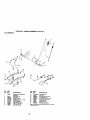
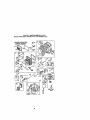
TO REMOVE MOWER
Mower will be easier to remove from the
rightside of tractor.
1. Place attachment clutch in "DISENGAGED _ position.
2. Move attachment lift lever forward to
lower mower to its lowest position.
3. Roll belt off engine pulley.
4. Remove small retainer spring, and lift
clutch spring off pulley bolt,
5. Remove large retainer spring, slide
collar off and push housing guide out
of bracket.
6. Disconnect anti-swaybar from chassis
bracket by removing retainer spring.
7. Disconnect suspension arms from
rear deck brackets by removing
retainer spdngs.
8, Disconnect front links from deck by
removing retainer springs.
9. Raise lift lever to raise suspension
arms, Slide mower out from under
tractor.
IMPORTANT: If an attachment other than
the mower deck is to be mounted on the
tractor, remove the front links and hook
the clutch spring Into square hole in
frame.
TO INSTALL MOWER
1. Raise attachment lift lever to its
highest position.
2. Slide mower under tractor with
deflector shield to right side of tractor.
3. Lower lift lever to its lowest position.
4. Install mower in reverse order of
removal instructions.
TO LEVEL MOWER HOUSING
Adjust the mower while tractor is parked
on level ground or driveway. Make sure
tires are properly inflated (See "PRODUCT SPECIFICATIONS" section of this
manual), tf tires are over or
undednflated, you will not properly adjust
your mower.
SIDE-TO-SIDE ADJUSTMENT
• Raise mower to its highest position.
• At the midpoint of both sides of mower,
measure height from bottom edge of
mower to ground. Distance "A" on
both sides of mower should be the
same or within 1/4" of each other.
Small Retainer Spdng
Clutch S
Link
Retainer S
Ant_-Sway
gs
(Both Sides)
HousingGuide
Large R
21
• Ifadjustment
isnecessary,
make
o\ \
adjustment on one side of mower only.
• To raise one side of mower, tighten lift
link adjustment nut on that side.
• To lower one side of mower, loosen lilt
link adjustment nut on that side.
NOTE: Each full turn of adjustment nut
will change mower height about 1/8".
• Recheck measurements after adjusting.
Bottomedge of
Bottomedge of
grm_Wne_
t__rWoeur
A--t-
,
/
Mandrel
BothFrontLinks Shouldbe Equalin Length
t_
--JTA
Arm
LiftLink
AdjustmentNut ------'--'--
_
Nut =_
Trunnion_
--
FRONT-TO-BACK ADJUSTMENT
IMPORTANT: Deck must be level side-toside.If the following front-to-back adjustment is necessary, be sure to adjust both
front linksequally so mower will stay
level side-to-side.
To obtain the best cutting results, the
mower housing should be adjusted so
that the front is approximately 1/8" to 1/2"
lower than the rear when the mower is in
its highest position.
Check adjustment on right side of tractor.
Measure distance "D" directly in front and
behind the mandrel at bottom edge of
mower housing as shown.
• Before making any necessary adjustments, check that both front links are
equal in length.
• If links are not equal in length, adjust
one link to same length as other link.
• To lower front of mower loosen nut "E"
on both front links an equal number of
turns.
• When distance "D" is 1/8" to 1/2" lower
at front than rear, tighten nuts "F'
against trunnion on both trent links.
• To raise front of mower, loosen nut "F"
from trunnion on both front links.
Tighten nut "E" on both front links an
equal number of turns.
• When distance "D" is 1/8" to 1/2" lower
at front than rear, tighten nut "F" against
trunnion on both front links.
• Recheck side-to-side adjustment,
Front Links
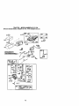
TO REPLACE MOWER BLADE DRIVE
BELT
The mower blade drive belt may be
replaced without tools. Park the tractor on
level surface. Engage parking brake.
BELT REMOVAL 1. Remove mower from tractor (See "TO
REMOVE MOWER" in this section of
this manual).
2. Work belt off both mandrel pulleys and
idler pulleys.
3. Pull belt away from mower.
BELT INSTALLATION 4. Install new belt in reverse order of
removal.
5. Make sure belt is in all pulley grooves
and inside all belt guides.
6, Install mower in reverse order of
removal instructions.
Mandrel
Mandrel
Pulley
22
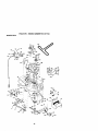
TO ADJUST BRAKE
Your tractor is equipped with an adjustable brake system which is mounted on
the right side of the transaxle.
If tractorrequires more than six (6) feet
stopping distance at high speed in highest
gear on a level dry concrete or paved
surface, then brake must be adjusted.
1. Depress clutch/brake pedal and
engage parking brake.
2. Measure distance between brake
operating arm and nut "A"on brake
rod.
3. tf distance is other than 1-1/2 =, loosen
jam nut and turn nut "A" until distance
becomes 1-1/2". Retightenjam nut
against nut "A".
4. Road test tractor for proper stopping
distance as stated above. Readjust if
necessary. If stopping distance is still
greater than six (6) feet in highest
gear, further maintenance is necessary. Contact a Sears or other
qualified service center.
WITH PARKING BRAKE "ENGAGED"
Engine Pulley-
Clutchin,
Stationary Idler
Transaxle
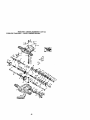
TRANSAXLE GEAR SHIFT LEVER
NEUTRAL ADJUSTMENT
The transaxle should be in neutral when
the gear shift lever is in neutral (N) (lock
gate) position.The adjustment is preset at
the factory; however, if adjustment is
needed, proceed as follows:
1. Make sure transaxle is in neutral (N).
NOTE: When the tractor rear wheels
move freely, the transaxle is in neutral.
2. Loosen adjustment bolt in front of the
right rear wheel.
3. Position the gear shift lever in the
neutral (N) position.
4. Tighten adjustment bolt securely.
NOTE: If additional clearance is needed
to get to adjustment bolt, move mower
deck height to the lowest position.
Gearshift Lever
Nut "A"
Jam Nut
TO REPLACE MOTION DRIVE BELT
Park the tractor on level surface. Engage
parking brake. For assistance, there is a
belt installation guide decal on bottom
side of left footrest.
1. Remove mower (See "TO REMOVE
MOWER" in this section of this
manual.)
2. Remove belt from stationary idler and
clutching idler.
3. Pull belt slack toward rear of tractor.
Remove belt upwards from transaxle
pulley by deflecting belt keepers.
4. Pull belt toward front of tractor and
remove downwards from around
/
_.
I
Adjustment Bolt
23
Neutral
Lock Gate
TO ADJUST STEERING WHEEL ALIGNMENT
If steering wheel crossbars are not
horizontal (left to right) when wheels are
positioned straight forward, remove
steering wheel and reassemble per
instructions in the Assembly section of
this manual,
FRONT WHEEL TOE-IN/CAMBER
The front wheel toe-in and camber are
not adjustable on your tractor. If damage
has occurred to affect the front wheel toein or camber, contact a Sears or other
qualified service center.
TO REMOVE WHEEL FOR REPAIRS
t. Block up axle securely.
2. Remove axle cover, retaining ring and
washers to allow wheel removal (rear
wheel contains a square key - Do not
lose).
3. Repair tire and reassemble.
NOTE= On rear wheels only: align
grooves in roar wheel hub and axle.
Insert square key.
4. Replace washers and snap retaining
ring securely in axle groove.
5. Replace axle cover.
NOTE: To seal tire punctures and prevent
flat tires due to slow leaks, tire sealant
may be purchased from your local parts
dealer. 3"ire sealant also prevents tire dry
rot and corrosion.
_Xolvee
r_l
_gWas:_sO
On,.)"
I
TO START ENGINE WITH A WEAK
BA'n'ERY
CAUTION: Lead-acidbatteries generate
explosivegases. Keep sparks, flame and
smokingmaterials away from battef",=s.
Always wear eye protectionwhen around
batteries.
If your battery is too weak to start the engine, it
should be recharged. (See "BA'I-FERY" in the
MAINI_NANCE sectionof this manual).
If "jumper cables"are used for emergency
starting, followthisprocedure:
IMPORTANT: Your tractoris equippedwitha
12 voltnegativegroundedsystem.The other
vehicalmust also be a 12 volt negalJve
grcunded system.Do not use your tractor
batte,_to startothervehicles.
TO ATTACHJUMPER CABLES 1. Connect each end of the RED cable to
the POSITIVE (+) terminal of each
battery, taking care not to short
against chassis.
2. Connect one end of the BLACK cable
to the NEGATIVE (-) terminal of fully
charged battery.
3. Connect the other end of the BLACK
cable to good CHASSIS GROUND,
away from fuel tank and battery.
TO REMOVE CABLES, REVERSE ORDER1. BLACK cable first from chassis and
then from the fully charged battery.
2. RED cable last from both batteries.
Positive Terminal
Negative Terminal
Cables
Charged
Terminal
ative
Terminal
REPLACING BAI-rERY
_, CAUTION: Do not short battery
terminals by allowing a wrench of any
other object to contact both terminals at
the same time. Before connecting battery,
remove metal bracelets, wristwatch
bands, rings, etc.
Positive terminal must be connected first
to prevent sparking from accidental
grounding.
1. Lift seat pan to raised position and
open battery box door.
2. Disconnect BLACK battery cable first
then RED battery cable and carefully
remove battery from tractor.
3. Install new battery with terminals in
same position as old battery.
4. First connect RED battery cable to
positive (+) terminat with hex bolt and
keps nut as shown. Tighten securely.
5. Connect BLACK grounding cable to
negative (-) terminal with remaining
hex bolt and keps nut. Tighten
securely.
6. Close battery box door.
Battery
Door
Positive (Red) Cable
24
Negative (Black)
Cable
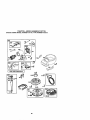
TO REPLACE HEADLIGHT BULB
1. Raise hood.
2. Pull bulb holder out of the bole in the
backside of the grill.
3. Replace bulb in holder and push bulb
holder securely back into the hole in
the backside of the grill.
4. Close hoed.
INTERLOCKS AND RELAYS
Loose or damaged widng may cause your
tractorto run poorly,stop running, or
prevent itfrom starting.
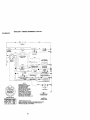
• Check widng. See electrical wiring
diagram in the Repair Parts section.
TO REPLACE FUSE
Replace with 20 amp automotive-type
plug-infuse. The fuse holder is located
behind the dash.
TO REMOVE HOOD AND GRILL ASSEMBLY
1. Raise hood.
2. Unsnap headlight wire connector.
3. Stand in frontof tractor. Grasp hood at
sides, tilt toward engine and lift off of
tractor.
4. TO replace, reverse above procedure.
Headlight Wire
Connector
ENGINE
Maintenance,repair,or replacementof the
emissioncontroldevicesand systems,which
are being done at the customers expense,
may be performed by any non-roadengine
repair establishment or individual.Wananty
repairs must be performed by an authorized
engine manufacturer's serviceouifeL
1. Wrth engine not running, move throttle
controllever from slowto choke
pos_on. Slowlymove lever from choke
tofast position.
2. Check that holes"A" in governor
controllever and hole in govemorplate
line-up, if holes "A" are not aligned,
loosen clamp screw and move throttle
cable until holes are aligned. "nghten
damp screw securely.
Governor
Governor
-_Contr0JILever
\_1
/Control
Sc-rew _"
Plate
Cable
TO ADJUST CARBURETOR
NOTE: The carburetoron this engine is low
emission, it isequippedwith an idlefuel
adjusting needle with a limitercap, which
allows some adjustmentwithin the limits
allowed by the cap. Do not attempt to remove
the limiter cap. The limitercap cannot be
removed without breaking the adjusting
needle.
The cad:_reto_has been preset at the factory
and adjustment should not be necessary.
However, minor adjustment may be required
to compensate for differences in fuel,
temperature, altitude orload, if the carburetor
does need adjustment, proceed as follows:
In geneS, turning idle mixture valve in
(_)
decreases the supplyof tuol to
the engine gMng a leaner fueVair mixture.
Turning the idle mixture valve out (counterdcokwise) increases the supplyof fuel to the
engine givinga richerfueVair mixture.
IMPORTANT: Damage to the needlevalve
and the seat in carburetormay resultif screw
isturnedin too tight.
PREUMINARY SE'I-FING1. Air cleaner assembly must be assembled
to the carburetor when making carburetor
adjustments.
2. Be sure the thro_e controlcable is
adjusted properly(see above).
FINAL SETTtNG 1. Startengine and allow to warm for five
minutes. Make finaladj_nts
with
engine runningand shift/motioncontrol
lever in neutral(N) position.
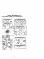
TO ADJUSTTHROTn_E CONTROL
CABLE
The throttlecontrolhas been presetat the
factoryand adjustment shouldnot be
necessary. Check adjLLstment
as described
below before looseningcable, if adjustn',,ent
is necessary,proceedas follows:
25
2. Move throtlie control loverto slow
position. With finger, rotate and hold
throttle lever against idlespeed screw.
Turn idle speed screw to attain 1750
RPM.
3. While still holding throttle lever against
idlespeed screw, tum idle mixture valve
lulltravet clockwise then counterdsekwise unlJlengine runsrough. Turn valve
to a point midway between those two
positions. Release throttie lever.
ACCELERATION TEST 4. Move throttle sentrol lever fromslowto
fastposition,ff engine hesitatesor dies,
lure idle mbtture valve out (counterclockwise) I/8 turn. Repeattest and cantinue
to adjust, if necessary,untilengine
accelerates smoothly.
Hk:jhspeed stop is factory adjusted. Do not
adjust - damage may result.
IMPORTAN'I_ Never tampor with tbe engine
governor, which is factory set for proper
engine speed, Overspeeding the engine
above the factory high speed setlJngcan be
dangerous. If you think the engine-governed
high speed needs adjusting, contacta Sears
or other qualified servK:ecenter, which has
proper equipment and experience to make
any necessary adjustments.
Idle Speed {-J _
With Limiter
26
_
Throttle
hose, or tank during storage. Also,
experiance indicates that alcohol
blended fuels (called gasohol or using
ethanol or methanol) can attract moisture
which leads to separation and formation
CAUTION: Never store the tractor
of acids during storage. Acidic gas can
with gasoline in the tank inside a building
damage the fuel system of and engine
where fumes may reach an open flame or
while in storage.
spark. Allow the engine to cool before
1. Drain the fuel tank.
storing in any enclosure.
2. Start the engine and let it run until the
fuel lines and carburetor are empty.
TRACTOR
•
Never
use engine or carburetor cleaner
Remove mower from tractor for winter
products in the fuel tank or permanent
storage. When mower is to be stored for
damage may occur.
a period of time, clean it thoroughly,
• Use fresh fuel next season.
remove all dirt, grease, leaves, etc. Store
NOTE: Fuel stabilizer is an acceptable
in a clean, dry area.
alternative in minimizing the formation of
1. Clean entire tractor (See "CLEANING"
fuel gum deposits during storage. Add
in the Maintenance section of this
stabilizer to gasoline in luel tank or
manual).
container. Always follow the mix
2. Inspect and replace belts, if necessary storage
ratio found on stabilizer container. Run
(See belt replacement instructions in
engine at least 10 minutes after adding
the Service and Adjustments section
stabilizer to allow the stabilizer to reach
of this manual).
the carburetor. Do not drain the gas tank
3. Lubricate as shown in the Mainteand carburetor if using fuel stabilizer.
nance section of this manual.
ENGINEOIL
4. Be sure that all nuts, bolts and screws
are securely fastened. Inspect moving Drain oil (with engine warm) and replace
with clean engine oil. (See =ENGINE" in
parts for damage, breakage and wear.
the Maintenance section of this manual).
Replace if necessary.
CYLINDER(S)
5. Touch up all rusted or chipped paint
1. Remove spark plug(s).
surfaces; sand lightly before painting.
2. Pour one ounce of oil through spark
BATI'ERY
plug hole(s) into cylinder(s).
• Fully charge the battery for storage.
3. Turn ignition key to "START" position
• After a period of time in storage, battery
for a few seconds to distribute oil.
may require recharging.
4. Replace with new spark plug(s).
• To help prevent corrosion and power
OTHER
leakage during long pedods of storage,
battery cables should be disconnected
• Do not store gasoline from one season
to another.
and battery cleaned thoroughly (see
"TO CLEAN BATTERY AND TERMI• Replace your gasoline can if your can
NALS" in the Maintenance section of
starts to rust. Rust and/or dirt in your
this manual).
gasoline will cause problems.
• If possible, store your tractor indoors
• After cleaning, leave cables disconand cover it to give protection from dust
nected and place cables where they
and dirt.
cannot come in contact with battery
terminals.
• Cover your tractor with a suitable
• If battery is removed from tractor for
protective cover that does not retain
moisture. Do not use plastic. Plastic
storage, do not store battery directly on
cannot breathe which allows condenconcrete or damp surfaces.
sation to form and will cause your
ENGINE
tractorto rust.
FUEL SYSTEM
IMPORTANT: Never cover tractorwhile
IMPORTANT: It is important to prevent
engine and exhaust areas are still warm.
gum deposites from forming in essential
fuel system parts such as carburetor, fuel
Immediately prepare your tractor for
storage at the end of the season or if the
tractor will not be used for 30 days or
more.
27
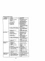
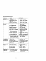
ROUBLESHOOTING
CHART
PROBLEM
Will not start
Hard to start
CAUSE
1. Out of fuel.
2. Engine not "CHOKED"
properly.
3. Engine flooded.
CORRECTION
1. Fill fuel tank.
2. See "TO START ENGINE"
in Operation section.
3. Wait several minutes
before attempting to start.
4. Replace spark plug.
4. Bad spark plug.
5. Clean/replace air filter.
5. Dirty air filter.
6. Replace fuel filter.
6. Dirty fuel filter.
7. Drain fuel tank and
7 Waterin fuel.
carburetor, refill tank with
fresh gasoline and replace
fuel filter.
8. Check all wiring.
8. Loose or damaged wiring.
9. Carburetor out of adjustment. 9. See "To Adjust Carburetor"
in Service Adjustments
section.
1O.Contact a Sears or other
10. Engine valves out of
qualified service center.
adjustment.
1. Dirty air filter.
2. Bad spark plug.
3. Weak or dead battery.
4. Dirty fuel filter.
5. Stale or dirty fuel.
: 6. Loose or damaged wiring.
7. Carburetor out of adjustment
8. Engine valvesout of
adjustment.
Englnewlllnot
turn over
1. Brake pedal not
depressed.
2. Attachment clutch is
engaged,
3. Weak or dead battery.
t. Depress brake pedal.
9. Faultyoperatorpresence
switch(es).
2, Disengage attachment
clutch.
3. Recharge or replace
battery.
4. Replace fuse.
5. Clean battery terminals.
6. Check all wiring.
7. Check/replace ignition
switch.
8. Check/replace solenoid or
starter.
9. Contact a Sears or other
qualified service center.
1.
2,
3.
4.
1.
2.
3.
4.
4.
5.
6.
7.
Blown fuse.
Corroded battery terminals.
Loose or damaged wiring.
Faulty ignition switch.
8. Faulty solenoid or starter.
Engine clicks but
will not start
1. Clean/replace air filter.
2. Replace spark plug.
3. Recharge or replace
battery.
4. Replace fuel filter.
5. Drain luel tank and refill
with fresh gasoline.
6. Check all wiring.
7. See "To Adjust Carburetor"
in Service Adjustments
section.
8. Contact a Sears or other
qualified service center.
Weak or dead battery.
Corroded battery terminals.
Loose or damaged wiring.
Faulty solenoid or starter.
28
Recharge or replace battery
Clean battery terminals.
Check all wiring.
Check/replace solenoid or
starter.
tROUBLESHOOTING CHART
, PROBLEM
Loss of power
CORRECTION
CAUSE
1. Cutting too much grass/too
fast.
2. Throttle in "CHOKE"
position.
13. Build-up of grass, leaves
and trash under mower.
4. Dirty air filter.
5. Low oil level/dirty oil.
6. Faulty spark plug.
1. Set in "Higher Cut" position/
reduce speed.
2. Adjust throttle control.
3. Clean underside of mower
housing.
4. Clean/replace air filter.
5. Check oil leveVchangs oil.
6. Clean and regap or change
spark plug.
7. Replace fuel filter.
7. Dirty fuel filter.
8. Drain fuel tank and refill with
8. Stale or dirty fuel.
fresh gasoline.
9. Drain fuel tank and carbure
9. Water in fuel.
tor, refili tank with fresh
gasoline and replace fuel
filter.
10.Connect and tighten spark
10.Spark plug wire loose.
plug wire.
1.Clean engine air screen/fins.
11. Dirty engine air screen/fins.
12.Clean/replace muffler.
12. Dirty/clogged muffler.
13.Check all wiring.
13.Loose or damaged wiring.
14.Carburetor out of
14.See "To Adjust Carburetor"
in Service Adjustments
adjustment.
section,
15.Contact a Sears or other
15.Engine valves out of
qualified service center.
adjustment.
Excessive
vibration
1. Worn, bent or loose blade.
2. Bent blade mandrel.
3. Loose/damaged part(s).
1. Replace blade.
Tighten blade bolt.
2. Replace blade mandrel.
3. Tighten loose part(s).
Replace damaged parts.
Engine continues
to run
when operator
leaves seat with
with attachment
clutch engaged
1. Faulty operator-safety
presence control system.
1. Check wiring, switches and
connections. If not
contact a Sears or other
qualified service center.
Poorcut-uneven
1. Worn, bent or loose blade.
1. Replace blade. "nghtsn
blade bolt.
2. Level mower deck.
3. Clean underside of mower
housing.
4. Replace blade mandrel.
5. Clean around mandrels to
open vent holes.
2. Mower deck not level.
3. Buildup of grass, leaves,
and trash under mower.
4. Bent blade mandrel.
5. Clogged mower deck vent
holes from buildup of
grass, leaves, and trash
around mandrels.
29
TROUBLESHOOTING
CHART
PROBLEM
Mower blades will
not rotate
Poor grass
discharge
CAUSE
1. Obstruction in clutch
mechanism.
2. Worn/damaged mower
drive belt.
3. Frozen idler pulley.
4. Frozen blade mandrel.
CORRECTION
1. Engine speed too slow.
1. Place throttle control in
"FAST" position.
2. Shift to slower speed.
3. Allow grass to dry before
mowing.
4. Level mower deck.
5. Check tires for proper air
pressure.
6. Replace/sharpen blade.
Tighten blade bolt•
7. Clean underside of mower
housing.
8. Replace mower drive belt. i
9. Reinstall blades sharp edge
down.
10. Replace with blades listed
in this manual.
11.Clean around mandrels to
open vent holes.
2. Travel speed too fast.
3. Wet grass.
.• Mower
deck not
Low/uneven
tire level.
air
pressure.
6. Worn, bent or loose blade.
7. Buildup of grass, leaves
and trash under mower.
i81 Mower
belt worn.
Blades ddve
improperly
installed.
t 0.Improper blades used.
11. Clogged mower deck vent
holes from buildup of grass,
leaves, and trash around
mandrels.
Headlight(s) not
working
(if so equipped)
.•
3.
4.
5,
Battery will not
charge
2. Replace mower drive belt.
3. Replace idler pulley.
4. Replace blade mandrel.
1. Turn switch "ON".
Switch
Bulb(s) isor"OFF'.
lamp(s) burned oul 2. Replace bulb(s) or lamp(s)•
Faulty light switch.
3. Check/replace light switch.
Loose or damaged wiring.
4. Check wiring end connec
tions.
Blown fuse.
5. Replace fuse.
1. Bad battery cell(s)•
2. Poor cable connections•
3. Faulty regulator
(if so equipped).
4. Faulty alternator•
Engine "backfires"
when turning
engine "OFF"
1. Remove obstruction.
1. Replace battery.
2. Check/clean all connec
tions.
3. Replace regulator.
4. Replace alternator.
1. Engine throttle control not
set at "SLOW" position
for 30 seconds before
stopping engine•
3O
1. Move throttle control to
"SLOW" position and allow
to idle for 30 seconds befor
stopping engine.
_.p_c_'oP,'" _OOP_L_B_'_
917._-7_'/33
TRACTOR - - MODEL NUMBER 917.271733
ELECTRICAL
22
25
32
TRACTOR -- MODEL NUMBER 917.271733
ELECTRICAL
KEY PART
NO, NO.
DESCRIPTION
1
2
8
16
21
22
24
_5
26
27
28
29
30
33
40
41
42
43
45
52
Batter 7
Bolt Hex Hd 1/4-20unc x _4
Case Battery
Switch, Interlock
Harness Asm Light W/4152j
Buib Light #1156
Cable Battery 6 Ga 11" red
Cable Battery 6 Ga w/16 wire red
FUSe20AMP
Nut Keps Hex 1/4-20 Unc
Cable GrOund 6 Ga 12* black
Switch Plunger
Switch Ign
Key Ign
Hantess Ign
Bolt BIk. Fin Hex 1/4-20 Unc x 1/2
Cover Terminal Rab
Soler,_k:l
Ammeter Rectangu{ar 6 Amp
Protection Wire Loop
144925
74760412
156417
15,3664
175688
4152J
4799J
146147
175158
73510400
4207J
121305X
175566
140403
178437
711104(_
131563
178_61
121433X
141940
NOTE: All component dimensions given in U.S. inches
1 inch = 25.4 mm
33
TRACTOR - - MODEL NUMBER 917.271733
CHASSIS AND ENCLOSURES
53
U/5
20a
9
7
54
207
64
,PO
208
34
TRACTOR - - MODEL NUMBER 917.271733
CHASSIS AND ENCLOSURES
KEY PART
NO, NO.
1
2
3
5
9
10
11
12
13
14
17
18
25
26
28
29
30
31
37
38
51
52
53
54
55
57
60
64
74
114
115
142
143
144
145
159
206
207
206
211
212
--
DESCRIPTION
174619
Chassis
176554
17660612
Screw 3/8-16 x 3/4
155272
Bumper Hood/Dash
168337X013 Dash
ST[T333710 Bolt, Carriage 3/8-16xl
155927
panel, Dash, LH.
145660
Clip Tin nerman Grille P,'I.
172107X010 Panel, Dash. R.H.
17490608
Screw Thdrol 3/8-16 x 1/2
144983X558 HoOd Assembly
126938X
Bumper Hood
19131312
WaSher 13/32 x 13/16 x 12 Gauge
STD541437
Nut
178987X558 GrUle w/Lens Asm.
155217)(599 Lens, Grille
175692)(558 Fend!Ftrest
139976
Bracket, Fender SuppOd
1749C506
Screw Thdrol 3/16-18 x 1/2
175710
Pivot Bracket Assembly, Rear
73800400
Nut Lock w/Insert 1/4-20 UNC
19091416
Washer 9/32x7/Sx
16Ga.
145201
Bracket Grille Pickoff LH
161464
Screw Hex Wshd 8-18 x 7/8
145202
Bracket Grifle Pickoff RH
STD522507
Bolt, Fin Hex 1/4-20 UNC x .75
72140606
BO_IRdhd Sqnk 3,/8-16 UNC x 3/4
154798
Dash Lower STLT
STD541437
Nut Crowniock 3/8-16 UNC
158112
Keeper Belt Rear Lh Stl 1=930
17060620
Screw 3/8-16 x 1-1/4
165867
Plate Reinforcement STLT
154966
Bracket Swaybar Chassis
175582
Bracket Pnt Footrest STLT
156524
Rod Pivot Chassis,,14ood
155123X428 CupholdarSlttBlack
170165
Bolt Shoulder 5/16-18Tr
17670508
Screw Thdrol 3/16-1B x 1/2 Tytt
17670608
Screw Thdrol 3/8-16 x 1/2
145212
Nut Hex Flange Lock
165919
Insert Lens Reflective
5479J
Plug, Button
NOTE: All component dimensions given in U.S. inches
1 inch = 25.4 mm
35
TRACTOR
- - MODEL NUMBER 917.271733
GROUND DRIVE
57
:36
TRACTOR -- MODEL NUMBER 917.271733
GROUND DRIVE
KEY PART
NO, NO,
1
2
3
4
5
6
8
10
11
13
14
16
18
19
21
22
24
25
26
27
28
29
30
32
34
35
36
37
38
39
40
41
42
47
48
49
50
51
52
53
55
56
57
59
61
........
DESCRIPTION
Transaxle (See BreakdOwn)
PeedesS 206-545C
146682
Spring, Return, Brake
123666X
Pulley, Transaxle
120000_8
Ring, Retainer
121520X
Strap, Torque
17060512
Screw 5/16-18 x 3/4
165866
Rod Shifter Fender STLT
STiTo61210 Pin, Cotter
105701X
WaSher, Shift Plate
74550412
Bolt 1/4-28 UNF W/Patch Gr. 8
10040400
Washer Lock Hvy Helical
ST[To41431 Nut Lock Hx W/Ins 5/16-18 x Gr.5
STD523710 Bolt Fin Hex 3/8-16UNC x 1 Gr. 5
STD541437 Nut
1068_X
Knob
13(_04
Rod, Brake
S_Yo41237
Nut
106_8X
Spdng, Brake Rod
STIr51037
Washer
S]O561210
Pin
175765
Rod, Parking Brake
71673
Cap, Parking Brake
169592
Bracket, Transaxle
STD523107 Bolt
175578
Shaft Assembly, Foot Pedal Nibbed
120183X
Beadng, Nylon
STD5510_2 Washer
STD571810 Roll Pin
165936
Pulley, CompOsile, Flat
74760648
Bolt
175461
Spacer, Split .395 x .59
175556
Keeper, Belt, Idler
19131312
Washer 13/32 x 13/16 x 12Ca.
127783
Pulley, Idler, V-Groove, Plastic
154407
Bencrank Clutch Grad Dw Stl
12_X
Retainer, Bolt
ST[T_23715 Bolt
STD541437 Nut Crown Lock 3/8-16 UNC
STD541431 NUt Crown Lock 5/1 6-18 UNC
105710X
Link, Clutch
105709X
Spdng, Clutch Return
17060616
Screw 3/6-16 x 1.0
130801
V-Beft, Ground Drive
169691
Keeper, Belt, Center Span
17060612
Screw 3/8-16 x 5/4
KEY PART
NO. NO.
DESCRIPTION
62
63
64
65
66
70
74
75
76
77
78
79
80
81
82
83
84
85
89
90
96
112
113
116
120
145
150
151
156
158
159
161
162
163
164
165
166
168
169
170
197
1_
2(_
212
Cover, Pedal
Pulley, Engine
Bert, Hex 7/16-20 x 4 Grade 5
Washer
Keeper, Belt, Engine, Four PrOOf
Guide, Mower Calve Belt, R.H.
spacer. Axle
Washer 25/32 x 1-1/4 x 16 Ca.
E-Rieg
Key, Squere 2.0 x .1845/1865
Washer 25/32 x 1-5/8 x 16 Ga
Key Woodruft
Arm. Shift
Shaft Asm Cross Tapered 650 20
Spdng,Torslen
Washer 17/32 x 3/4 x 16 Ca.
Link Transaxle
Nut, NyloCk
Console, Shift, STLT
Nut, SelfoThding, Wsh Hd 1/4
Retainer Spring 1"
Washer 9/32x3/4x
10Ca.
Strap Torque 90 Degrees
Bolt Rdhd Sqneck 3/8-16 x 1
Nut LOck Fig 3/8-16
Belt. Hex Flghd 5/1 6-18 Gr. 5
Specer Retainer
Washer 13/32 x 2 x 10 Ca.
Washer Srded 5/161D x 1.125
Bracket Shift Mount
Hub Tapered Range Shift Lt
Bolt Rdhd Sqnk 1/4-20 x 3/4 Gr.5
Nut Crownleck 1/4-20 Unc
Bo_t Hex Fie I/4-20Unc x 1Gr 5
WaSher 5/8 x .281 x 10 Ga
Bracket Pivot Lever
Screw 5/16-18 x 5/8
Bolt Shoulder 5/16-18 x .561
Plete Fastening Lt
Keeper Beft Transaxle Gear
Nyliner Snap-In
Washer Nyliner
Bolt Cart. SH 3'8-16 x 1-3"4 Gr. 5
Nut Hex Flange Lock
8883R
175410
71170764
8T_51143
154778
134683
137057
121749)(
STC581075
123583X
121748X
STD580025
145090
165592
165711
19171216
166231
150360
158391X428
124346X
STD624(X)3
19091210
127285X
72140608
739(3(3600
74490540
175456
19133210
166002
165589
165494
72140406
73680400
74780416
19091010
165_3
166880
165492
165580
173898
169613
169593
72110614
145212
NOTE: /_JIcomponent dimensions given in U. S. inches
1 inch = 25,4 mm
37
TRACTOR
- - MODEL NUMB ER 917.271733
STEERINGASSEMBLY
TRACTOR
-- MODEL
NUMBER
917.271733
STEERING
ASSEMBLY
KEY PART
NO, NO,
1
2
3
4
5
6
7
8
9
10
11
13
15
17
26
28
29
3O
32
36
37
38
39
4O
41
42
43
44
46
47
51
54
63
65
67
68
71
85
88
91
139768
154427
169840
169839
6266H
121748X
19272016
12000029
3366R
175121
STD551137
13_518
145212
177876
126847X
19131416
17060612
STD561210
130465
155099
152927
139769
19133812
S]1:Y'o41537
100711L
145054X428
121749X
15,3720
121232X
6855M
STD541431
74780520
STD523710
160_67
72140618
16..o827
175146
169835
133835
175118
175553
DESCRIPTION
Steedng Wheel
Axle Assembly STMP Dropped STL
Spindle Assembly, LH.
Spindle Assembly, R.H.
Bearing, Race, Thrust, Hardened
Washer 25/32 x 1-5/8 x 16 Gauge
Washer 27/32 x 1-1/4 x 16 Gauge
Ring, Klip
Beanng, Steering Co;umn
Draglink
Washer, Lock
Specer Seadng Axle Front
Nut, Hex P]ange Lock
Shaft Assembly, Steedng
Bushing, Link, Drag
Washer 13/32 x 7/8 x 16 Gauge
Scrsw 3/8-16 x 3/4
Pin Cofter
Rod,Tie
Bushing, Steering
Screw
InSert, Steering Wheel
Washer "i3/32 x 2-3/8 x 12 Gauge
Ntd Lock Center 3/8-24 Unf
Adaptor, Sleering Wheel
Boot, Steering Shaft
Washer 25/32 x 1-1/4 x 16 Gauge
Extension Shaft Steedng LR.LT
Cap, Spindle
Fitting, Grease
NutLockHexw/Ins.
5/16-18UNC
Bolt F_n Hex 5/16-18 UNC x 1-1/4
Bolt, Fin Hex 3/8-16 UNC x 1Gr 5
Spacer Brace Axio
Bolt RDHD Sqnk 3/8-16 x 2-1/4
Axle, Brace
Steedng Asm.
Bracket Susp. Chassis Front
Fastener Christmas Tree
Boft Shoulder 7/16-20
Clip Steering
NOTE: All component dimensions given in U.S. inches
1 inch = 25,4 mm
39
TRACTOR -- MODEL NUMBER 917.271733
ENGINE
81
29
\
OPTIONAL
EQUIPMENT
Spark Arrester
KEY
NO.
PART
NO.
1
2
170545
17720410
3
......
4
13
14
16
23
29
31
32
33
137352
165291
148456
ST[To51231
169837
137180
1_
158990
123487X
DESCRIPTION
Control.Throttle
Screw, Hex Head, Thread Cutting
1/4-20 x 5/8
Engine, (See Breakdown)
Br_ggsModel 311707-0125-E1
Muffler
Gasket
Tube Oil Drain Easy
Washer
Shield Bm/Dbr Guard
Arrestor, Spark
Tank, Fuel
Cap AsSembly, Fuel Sears, Vented
Clamp.Hose
KEY
NO.
PART
NO.
37
38
40
44
137040
148315
124028X
17670412
45
46
62
72
78
81
17C_12
19091416
STD551131
71070512
17060620
73510400
DESCRIPTION
Line, Fuel
Plug C_I Drain Easy
Bushing, Snap, Fuel Line
Screw, Hex Washer Head, Thd.,
Roll. 1/4-20 x 3/4
Screw Hexwsh Thdr 3/8-16 x 3/4
Washer 9/32 x 7/8 x 16 Gauge
Washer, Lock
Screw Hex Hd Cap 5/16-18 x 3/4
Screw 3/8-16 x 1-1/4
Nut Keps Hex 1/4-20 Unc
NOTE: All component dimensions given in U.S. inches
1 inch = 25.4 mm
4O
TRACTOR
- - MODEL NUMBER
917.271733
SEAT ASSEMBLY
\
\
KEY
NO,
1
2
3
4
5
6
7
8
9
10
11
12
PART
NO.
140123
140551
71110616
19131610
1_
STD541437
124181X
170(_616
19131614
174894
166369
121246X
DESCRIPTION
Seat
Bracket Pnl Pivot Seat (blk)
Bolt Fin Hex 3/8-16unc X 1
Washer 13/32 X 3/4 X 10 Ga
Clip Push In Hinged
Nut Hex Lock w/Ins 3/8-16 unc
Spring Seat Cprsn 2 250 BIk Zi
Screw 3/8-16 X 1
Washer 13/32 X 1 X 14 Ga
Pan Phi Seat
Knob Segt Adj Wingnut
Bracket Pnt Mounting Sw_tch
KEY PART
NO. NO.
13
14
15
16
17
21
22
24
25
121248X
72050412
134300
121250X
123976X
171852
ST_o41431
19171912
127018X
DESCRIPTION
Bushing Snap BIk Ny150 Id
Bolt Rdhd Sht Nk 1/4-20x1-1/2
Spacer Spilt 28 X 96 Zinc
Spdng Cprsn 1 27 BIk Pnt
Nut Lock 1/4 Lge FkJ Gr 5 Zinc
Bott Shoulder _16-18 Unc-2A
Nut Hex Lock w/Ins _16-18
Washer 17/32 X 1-3/16 X12Ga.
Bolt Shoulder 5/16-18 X 62
NOTE: All component dimensions given in U.S. inches
1 inch = 25.4 mm
41
TRACTOR--
MODEL NUMBER 917.271733
DECALS
13
14
KEY
NO.
PART
NO.
1
2
3
4
5
6
7
8
156368
171760
171696
171697
176680
133644
177253
172331
10
156439
DESCRIPTION
Decal, Oper. Instr.
Decal, ReplaCement
Decal, Hood, R.H.
Decal, Hood, LH.
Decal, HP Engine
Decal, Customer Maintenance
Decal,Hood S_de
Decal, Mower Heavy Duty 12 Ga.
Decal, Fender, Craftsman
Decal, Fender Danger
WHEELS & TIRES
2_
5,11
4,10
7
It
KEY
NO.
PART
NO.
DESCRIPTION
12
13
14
20
------
146046
177255
160396
149516
138311
165800X428
165799X428
179171
179172
Decal, "/*Belt Drive SChematic
Decal, Lower Dash
DeCal, V- Bell Sche rnatic
Decal Battery Dngr/Psn Eng
Decal,L_ Handle
Pad Footrest LH STLT
PadFOOtrestRHSTLT
Owner's Manual, English
Owner's Manual, Spanish
KEY
NO.
PART
NO.
1
2
3
4
5
6
7
8
9
10
11
--
59192
Cap Va]ue 1"ire
65139
Stem Value
106222X
"13reF Ts 15 X 6 0 - 6 Service
59904
Tube Inner Front #35060
106732X427 Rim Asm 6"front White Service
278H
Fitting Grease
9040H
Searing Flange
106108X427 Rim Asm 8"rear White Service
122_X
Tire R Ts ;._0X I 0-8 Service
7152J
Tube Rear 9 5 X 8 Ser_Jce
104757X428 Cap Axle Elk 1 50 X 1 00
1443,34
Sealant, Tire (10 oz. tube)
DESCRIPTION
NOTE;/MI component dimensions given in U.S. inches
1 inch = 25.4 mm
42
TRACTOR
-- MODEL NUMBER
917.271733
LIFTASSEMBLY
KEY
NO,
PART
NO.
1
159460
2
3
4
5
6
7
8
11
12
159471
105767X
120000(_
19211621
120183X
125631X
122365X
13o_65
139e66
DESCRIPTION
KEY
NO.
Washer Asm Inner Spdng
W/Plunger
Shaft Asm. Lilt
Pin Groove
E Ring #5133-62
Washer 21/32 x 1 x21 Ga.
Beadng Ny_ong
GtipHandleRuted
Button Plunger Read
Link Asm Lift L.H.
Link Asm Lift R.H.
13
$3_624066
Retainer Spdng
15
173288
Link Front
16
73350800
Nut Jam Hex 1/2-13 Uric
17
175689
Trunnion BIk Zinc
18
73800800
Nut Lock w/_Vsh 1/2-13 Uric
19
139e68
ArmSuspens_on Mower
20
163552
Retainer Spring
31
169e65
Beadng, Pvt Lilt
32
73540600
Nut Crownlock 3/8-24
NOTE: All component dimensions given in US. inches
1 inch = 25.4 mm
43
PART
NO.
DESCRIPTION
TRACTOR
-- MODEL NUMBER 917.271733
MOWERDECK
l
111 _
21 22
44
TRACTOR
-- MODEL NUMBER
917.271733
MOWERDECK
KEY PART
NO. NO.
1
2
3
4
5
6
8
9
10
11
13
14
15
16
18
19
20
21
22
23
24
25
26
27
28
29
30
31
3_
33
34
36
37
40
44
45
46
48
49
50
51
52
53
54
55
KEY PART
NO. NO.
DESCRIPTION
165892
STD533107
138017
Mover Housing
Boll
Bracket Assembly,Sway Bar,
Front
165460
Bracket Sway Bar 38/42"
S'n3_240(_
RetaJnerSpdng
130832
Arm, Suspension, Rear
850857
Bolt, Hex 3/8-24 x 1.25 Gr. 8
ST[ToSt137 Washer, Lock
14_o86
Washer, Hardened
134149
Blade, Mulching
137645
Shaft Assembly, Mandrel, Vented
(Incl. Key Number 6)
128774
Rousing, Mandrel, Vent ed
110485X
Beadng, BalI, Maedrel
174493
Stripper, Mower Deck
721405(_
Bolt, Carriage 5/16-18 x 5/8
132827
Bolt, Shoulder
159770
Baffle, Vortex
ST[To41431 Nut,Crowntock5/16*lSUNC
134753
Stiffener Bracket
131267
Bracket. Deflector
105304X
Cap, Sleeve
123713X
Spring, Torsion, Deflector
110452X
Nut, Push
130968X428 Shield, Deflector
19111016
Washer 11/32 x 5/8 x 16 Ga.
131491
Rod.Hinge
157722
Screw Thdrol Rolling Wsh Hd
129963
Washer, Spacer
153535
Pulley, Mandrel
178342
Nut,Toplock, Flangod
STD533717
Boll
131494
Pulley, Idler, Flat
19131316
Washer13132x19/16x16Ga.
ST[To41437 Nut, Crownlock 3/8-16 UNC
140088
Guard, Mandrel, LH.
STD624003
Retainer
137729
Screw, Thd. Roll 1/4-20 x 5/8
133944
Washer, Hardened
174284
RollerAssembly,CamFollower
131340
Boll, Shoulder #10-24 Grade 5
STC541410
Leckn_
139888
Boll, Sheulder 5/16-18 UNC
131845
Arm Assembly, Pad. Brake
13.3943
Washer, Hardened
155046
Aml, Idler
56
59
67
68
92
101
l(_Z
103
104
105
106
111
112
113
114
115
116
117
118
119
129
130
131
142
143
144
145
146
147
148
149
150
151
152
153
154
155
156
157
158
159
°-
165723
141043
149846
144959
STD5414.37
136420
71081010
19061216
ST[To51110
160793
2029J
174925
174_6
17060512
73510500
72110504
4898H
165746
739306_)
19121414
19131312
ST[To23710
STD533710
165890
157109
158634
165888
171977
131335
169(_2
165898
19C91216
169670
169676
169674
169675
169671
169672
169669
17720410
STD533717
130794
--
169583
DESCRIPTION
Spacer, Retainer
Guard, Tuv idler (94)
Knob Custam Oval
V-Bell
Locknut. Hex WANsh 3/8-16 UNC
CoverMulching42"Black
Screw Truss Hd Phil10-24 x5/8
Washer#10
WasherLock
Latch Asm Bagger
Nut Weld
Bracket Gauge, Wheel LH
Bracket, Gauge, Wheel RH
Screw 5/10-18 x 3/4
Nut, HexKeps 5/16-18UNC
Boll, Cardage 5/16 UNC x 1/2
Bolt, Shoulder
Wheel, Gauge
Nut, Crownldck 3/8-1
Washer 13/32x7/8x14Ga,
Washer 13/32 x 13/16 x 12 Ga.
Belt, Fin Hex 3/8-16 UNC x I Gr 5
BoltRdhdSqnk3/8-16UNCxl
Arm Spr;ng Brake Mower
Bracket Arm Idler 42"
KeeperBelt42"ClutchCabld
Pulley Idler Flat
Boll Carraige idler
Sphng Extension
Spring Return Idler
Retainer Spdng Yenow Zinc
Washer 9/32 x 3/4 x 16 Ga.
Bracket Clutch
Cable Clutch 42"
Washerflat 3i8"TypeB
Spdng Retainer
Spdng Retention Lever
Spacer
Rod Clutch
Screw Hex Thd Cut 1/4-20 x 5/8
BollRdhdSqn3/8-16Uncx1*3/4
Mandrel Assembly (includes Key
Numbers 8-10, 13-15, 31 aod 32)
R_ment
Mower, Completa
NOTE: All component dimensions given in U.S. inches
1 inch = 25.4 mm
45
TRACTOR
- - MODEL NUMBER 917.271733
PEERLESSTRANSAXLE - - MODEL NUMBER206-545C
47
13
29
46
TRACTOR -- MODEL NUMBER 917.271733
PEERLESSTRANSAXLE - - MODEL NUMBER206-545C
KEY
NO.
PART
NO.
t
2
3
4
5
6
6A
7
8
8A
9
10
11
12
13
14
15
17
18
20
21
22
25
25A
26
27
28
29
29A
29B
29C
30
31
772147
786086A
770128
776395
776409
778364
778369
778330
792180
792047
784352
784378
778334
778309
778368
778368
778370
786188
7861(72
79'2077A
792078
792079
792073A
792177
792125
792035
788040
780072
780160
780051
780199
780108
780001
31A
32
34
35
35A
36
37
38
39
40
780195
788083
780194
780193
780197
790075
79(;007
799021
786026
792076A
KEY
NO.
PART
NO.
41A
42
47J_,
43
44
45
46
47
48
49
50
5t
52
53
54
56
57
58
59
60
61
65
66
67
69
70
71
71B
76
77
79
82
83
65
87
150
157
180
900
79G079
792073A
792085A
792075
790025
786066
786086
774690
774691
778356
778338
778354
778352
778350
778346
778355
778337
778353
778351
778349
778345
780189
776422
776396
792170
786187
788069
78_092
780090
788078A
792144
778333
7783,38
792154
788089A
788093A
788088A
730229A
794712
DESCRIPTION
TransaxleCover
Needle Bearing 5/8"
TransaxleCase
Countershaft
Output Sha8
Spur Gear (38 teeth)
Spur Gear (15 teeth)
Spur Gear (11 teeth)
Shift Key
Woodruff Key #9
Shift Collar
Shift Rod & Fork
Bevel Gear (30 teeth)
Input Bevel Pinion (13 teeth)
Bevel Gear (13 teet h)(Include. 14)
Bevel Pinion (13 teeth)(Include. 13)
Ring Gear (43 teeth)
Drive Pin
Spacer 1.130 X .695
Ball 5/16" dia
Set Screw 3/8 - 16 x 3/8"
Spring .310 OD x .625 L
Screw 1/4 - 20 x 1-1/4"
Screw 1/4-20 x 1-3/8"
Retaining Ring (pkg of 2)
Retaining Ring
Retaining Ring
Thrust Washer ,627 ID x.031W
Thrust Washer ,762 ID x,O31W
Thrust Washer ,762 ID x.O31W
Anti-Rotation Washer ,632
Cup Washer 1.127 ID x .032W
Fiat Washer .750 ID x ,056W
(Use As Needed)
Fiat Washer ,750 ID x .062W
Oil Seal 5/8"
Bushing .563
Flanged Bushing 5 / 8" ID
FlangedBushing.751
Brake Disk
Brake Pad Plate
Brake Pad (pkg of 2)
Dowel Pin
Flat Washer .312 ID x .059W
DESCRIPTION
Brake Lever
Screw 1/4 - 20 x 1-1/4"
Screw 1/4 - 20 x 2 1/4"
Locknut 5 / 16 - 24
Brake Pad Holder
Spacer .2625 x 1.0
Brake Lever Bracket
Axle (11-15 / 16" Long
Axe ( 16 - 1 / 2" tong)
Spur Gear (29 teeth)
Spur Gear (27 teeth)
Spur Gear (23 teeth)
Spur Gear (19 teeth)
Spur Gear (16 teeth)
Spur Gear (15 teeth)
Spur Gear (11 teeth)
Spur Gear (13 teeth)
Spur Gear (17 teuth)
Spur Gear (21 teeth)
Spur Gear (24 teeth)
Spur Gear (25 teeth)
Flat Washer .563 ID x .062W
Input Shaft
Shifter & Brake Shaft
Retaining Ring
Spucer .890
Square Cut Riog
=O'Ring
Fiat Washer 1.128 ID x .058W
Inverted Retaining Ring
Spring ,430 OD x .5000 L
Bevel & Spur Gear (30 & 13 teeth)
Spur Gear (27 teeth)
Oil Fill Plug
Oil Seal 9 / 16"
Liquid Gasket RTV Silicone
Oil Seal 3/4"
Gear Oil 86W90
ReplacementMST-206-545C
Transa)de
NOTE: Aft component dimensions given in U.S. inches
I inch = 25.4 mm
47
TRACTOR
-- MODEL NUMBER 917.271733
BRIGGS ENGINE-MODELNUMBER 311707, TYPE NUMBER 0125-E1
INSTALL,SPECIALTOOLS
SEE REPAIR
-IkTO
REQUIRES
(NSTRUCTION MANUAL
_p
48
TRACTOR - - MODEL NUMBER 917.271733
BRIGGS ENGINE-MODELNUMBER 311707,TYPE NUMBER 0125-E1
8751 711_
968
/"
J
_i
445
,
°_
1_
185_
"_176_J344,_
616
240_
404 _ R
6141_
967_"
I 1019 LABEL KIT
|
216
222
_505_
634A
137_
49
TRACTOR -- MODEL NUMBER 917.271733
BRIGGSENGINE-MODELNUMBER 311707, TYPE NUMBER 0125-E1
311_
797
4620_
579
80"
697
I
1036 LABEL-EMISSIONS
I
034_
287 _
733_
789A
524_
5O
75_
TRACTOR
- - MODEL NUMBER 917.271733
BRIGGS ENGINE-MODELNUMBER 311707,TYPE NUMBER 0125-E1
977 CARBURETOR
121 CARBURETOR
GASKET SET .I
104_
51_
137Q
127_
OVERHAUL KIT
276_
987_
.4A_ 634_ 1.0
2760
95_
231_42R
1095 VALVE GASKET SET
137_
_
51_'_
358 ENGINE GASKET SET
3(_
524_)
883
842_
121A CARBURETOR
95A_p
51_
104A_
OVERHAUL KIT
276A_
127A_
IOSA_667A®
217._
127A(_
137AO
231A_
137A_
369_
I
51
51_
137A_
977A CARBURETOR
276A_
GASKET SET
TRACTOR
-- MODEL NUMBER 917.271733
BRIGGS ENGINE-MODELNUMBER 311707,TYPE NUMBER 0125-E1
KEY
NO.
1
2
3
4
5
7
8
9
10
11
12
13
15
16
20
22
23
24
25
PART
NO.
690156
399265
391086
494238
590188
692410
696126
27803
691666
691328
692226
•
o+
•
°
692406
•
692405
•
690360
690946
690136
291675
692125
693557
222698
692271
•
DESCRIPTION
C_lieder Assembly
Kit-Bushing/Seal
Seal-Oil (Magneto Side)
Sump-Engine
Head-Cylinder
Gasket-Cylinder
Head
Breather Assembly
Gasket-Breather
Screw (Breather Assembly)
Tube-Breather
Gasket-Crankcase
(.015 Thick,
Std)
Gasket-Crankcase
(.005
Thick)
Gasket-Crankcase
(.009
Thbck)
Screw (Cylinder Head)
Plug-Oil Drain
Crankshaft
Seal-Oil
Screw (Crankcase Cover)
Flywheel
Key-Flywheel
Piston Assembly (Standard)
50
51
53
54
73
74
75
78
93
94
94A
Piston Assembly
.020 O.S.
Piston
.l!)lO
Piston Assembly
Assembly
030 O.S.
O.S. I
Ring Set-Piston (Standard)
Ring Set-Piston (.010 O.S.)
Ring Set-Piston (.020 O.S.)
Ring Set-Piston (.030 O.S.)
Lock-Piston Pin
Pin-Piston (Standard)
Pin-Piston (.020 O.S.)
Rod-Connecting
(Standard)
Rod-Connecting
(.020 U.S.)
Screw._Connecting
Rod)
Valve-_xhaust
Valve-Intake
Spring-Valve (Intake)
Spring-Valve (Exhaust)
Guard-Flywheal
Retainer-Valve
Slinger-Governer/Oil
Tappet-Valve
Camshaft
Short Block (311707-0028-E1
Replacement
Engine)
690193
Manifold-Intake
692137o_t+Gasket-lntake
690227
Stud (Carburetor)
691148
Screw (Intake Manifold)
494439
Screen-Rotating
691057
Screw (Rotating Screen)
690582
Washer(Flywheel)
690661
Screw (Flywheel Guard)
690602
O Bushing-Throttle
Shaft
498030
Kit-Idle Mixture
695425
Kit-Idle Mixture
95A
95
98
98A
104
104A
105
105A
690718
691636
495800
695408
690525
694918
231855
694922
26
27
28
29
32
33
34
35
36
37
40
43
45
46
48
592273
692272
692274
690162
692164
692165
692168
691299
498319
498320
692419
692420
692852
495856
495857
691279
691279
690456
691752
691968
690564
692421
692706
a
_
_
_
_
_
Screw _hrottle
hroffie Valve I
Kit-Idle Speed
Kit-Idle Speed
Pin-Float Hinge
Pin-Float Hinge
Valve-Float Needle
Valve-Float Needle
KEY
NO.
106
108
108A
108B
117
117A
121
121A
125
125A
PART
NO.
690577
690464
692344
695419
692408
692411
695415
695416
690191
695427
690194
127
695005
127A 690727
130
691750
130A 695418
131
494379
131A 695421
133
494381
133A 694914
137
281165
137A 695426
141
495097
141A
495931
141B
142
146
167
176
185
186
187
695420
692412
691639
692297
691917
690958
692317
691050
_
_
(_
O
_
_l
_t
_t
Q
•
188
691693
192
691986
202
691841
209
692208
216
691840
217
695409
222
694042
227
691374
231
691636
Q
231A 690718
O
232
691842
238
591843
240
394358
265
691024
267
695134
276
692255 O_:
276A 695410 _
287
691002
304
691399
RPM Settings:
•
DESCRIPTION
Seat-Inlet
Valve-Choke (Manual Choke)
Valve-Choke(Choke-A-MaUc)
Valve-Choke(NikkJ Carburetor)
Jet-Main (Standard)
Jet-Main (High Altitude)
Jet-Main (Standard)
Jet-Main (High Altitude)
Kit-Carburetor Overhaul
Kit-Carburetor Overhaul
Carburetor
Carburetor (Nikki) (Service with
Walbro Carburetor)
Plug-Welch
Plug-Welch
Valve-Throttle
Valve-Throttle
Kit-Throttle Shaft
Kit-Throttle Shaft
Float-Carburetor
Float*Carburetor
Gasket-Float Bowl
Gasket-Float Bowl
Kit-Choke Shaft (Manual
Kit-Choke Shaft (Choke-AChoke)
Matic)
Kit-Choke Shatt (Nikki)
Nozzle-Carburetor
Key-Timing
Air Cleaner Stud Seal
O-Ring Seal (Air Cleaner)
Nut (Air Cleaner Base)
Connector-Hose
Line-Fual (Cut to Required
Length)
Screw (Control Bracket)
Adjuster-Rocker Arm
Link-Mechanical
Governor
Spring-Governor
Link-Choke
Spring-Choke Return
Bracket-Control
Control Lever*Governor
Screw (Choke Valve)
Screw (Choke Valve )
Spring-Governor
Link
Cap-Valve
Filtar-Fuel
Clamp-Casing
Screw (Casing Clamp)
Sealing Washer
Sealing Washer
Screw (Dipstick Tube)
Housing-Blower
Low Speed: 1900-2100
High Speed: 3000-3200
Included in Engine Gasket Set, Key. No. 358
Included In Carburetor Overhaul Kit, Key.
No. 121aed121A
t
Included in Carburetor Gasket Set, Key. No.
977 and 977A
+
Included in Valve Gasket Set. Key. No. 1095
NOTE:
All component dimensions given in U.S.
inches 1 inch = 25.4 mm
Q
52
TRACTOR
- - MODEL NUMBER 917.271733
BRIGGS ENGINE-MODELNUMBER 311707, TYPE NUMBER0125-E1
KEY
NO.
306
306
307
309
310
311
PART
NO.
690960
690499
691003
693551
690323
497608
334
333
337
344
358
363
369
383
404
445
462
467
474
503
505
510
513
523
524
525
544
552
562
579
601
614
616
617
633
634
691061
495859
491055
693675
690189
19203
695422
89838
691691
496894
691261
591668
691063
691532
691251
693699
692024
692014
281370
691398
692034
491986
691119
691029
95162
691620
692012
692138
695414
690801
O
634A
690802
_l
635
668
691
692
697
711
691909
691500
692407
690572
690372
690703
727
718
729
729A
732
733
741
757
758
759
761
783
789
789A
490324
690959
691335
691224
691002
691658
691284
691714
692423
691239
691096
693713
692037
695050
KEY
NO.
797
801
802
803
830
842
PART
NO.
693167
691429
691286
693757
691095
691870
Screw
(Armature Magneto)
Armature-Magneto
Spark Plug
Screw (Cable Clamp)
Engine Gasket Set
Flywheel Puller
_pSHng-FIoat Bow1
Wr ench-Spark Plug
Washer (Governor Crank)
Filter-Air Cleaner Cartridge
Washer Brush Retainer)
Knob-Ar Ceaner
Alternator
Strap-Starter
Nut Governor Control Lever)
Drve-Starter
Clutch-Drive
Dipstick
Seal-Dipstick Tube
Tube-Dtpstick
Armature-Starter
Bushing-Governor
Lever
Bolt (Governor Control Lever)
Nut (Starter Cable)
Clamp-Hose
Pin-Cotter
Crank-Governor
O-Ring Seal (Intake Manifbld
Seal-Choke/Throttle
Shaft
Seal-Spring Assembly
(Manual Choke
Seaf-Sprng
Assembly
_Choke-A-Matic)
Uoot-Spark Plug
Spacer
Seal-Governor
Shaft
Spring-Detent
Screw(Drive Cap
Screw (Carburetor Shield)
851
847
868
871
875
877
883
914
934
947
947A
950
950A
967
968
971
975
975A
977
977A
987
987A
996
1005
1006
1019
1022
1023
1026
692424
496415
690968
690969
696129
393456
692236
690960
691058
497672
695423
691657
695407
272403
691332
692129
495933
695417
690192
695428
691326
690998
690678
695492
690452
690180
272475
692492
692003
692011
691751
690822
695700
691265
274789
691293
691333
690190
691183
Settings:
Cover-Starter
Drive
Pin-Locating
Clip-Wire
Clip-Wire
Screw (Starter Ddve Cover)
Screw (Crankshaft Extension)
Gear-Timing
Link-Counterweight
Counterweight
Pin-Counterweight
Screw (Counterweight)
Gear-Pinion
Harness-Wiring
Hamess-Widng
RPM
DESCRIPTION
Screw (Blower Housing)
Shield-C,L.yllinder
Screw(Cylinder
Shield)
Motor-Starter
Screw (Starter Motor)
Brush Set
•
•
•
1029
1034
1036
1051
1058
1090
1091
1095
1119
-
DESCRIPTION
Nut (Brush Retainer)
Cap-Drive
Cap-End
Housing-Starter
Stud (Rocker Arm)
Dipstick/Tube Seal
Rug
+ Terminal-Spark
Dipstick/Tube Assembly
Seol-Valve
Bushing-Guide
Base-Air Cleaner
Wire-Connector/Alternator
• Gasket-Exhaust
Screw (Rocker Cover)
Screw _Fan Retainer
Soenold-Fuel
Solenoid-Fuel
Screw-Float Bowl
Screw-Float Bowl
Filtar-Pre Cleaner
Cover-Air Cleaner
Screw (Air Cleaner Base
Bowl-Float
Bow_-Fioat
Set-Carburetor
Gasket
Set-Carburetor
Gasket
Q Seal-Throttle
Shaft
_ Seal-Throttle
Shaft
Carburetor Shield
Fan-Flywheel
Retainer-Fan
Kit-Label
•+ Gasket-Rocker Cover
Cover-Rocker
Rod-Push (Intake)
Rod-Push (Exhaust)
Arm-Rocker
Guide-Push
Rod
Label-Emissions
Retainer-Brush
Owner's Manual
Retainer-Brush
Cap-Limiter
Valve Gasket Set
Screw (Alternator)
Low Seed:
1900-2100
High _o_eed: 3000-3200
in Engine Gasket Set, Key. No.
•
Included
358
Q
Included in Carburetor Overhaol Kit, Key.
No. 121and121A
_
Included Jn Carburetor Gasket Set, Key.
No. 977 and 977A
+
Included in Valve Gasket Set, Key. No.
1095
NOTE,_ All cornponent dimensions given in U.S.
inches 1 inch = 25.4 mm
53
SERVICENOTES
54
SUGGESTED
GUIDE
FOR SIGHTING
SLOPES
FOR SAFE
OPERATION
ONLY RIDE UP AND DOWN HILL,
NOT ACROSS HILL
GUIDE
Operate your Tractor up and down the face of slopes (not
greater than 15 ), never across the face. Make turns gradually to prevent tipping or loss of control. Exercise extreme
caution when changing direction on slopes.
I
I
I
For repairof major brand appliances in your own home..,
no matter who made it, no matterwho sold it!
1-800-4-MY-HOME ® Ar_, dayorr_ht
(1-8e0-4S94S_)
(U.S.A.
andCanada)
W'_WV.S_IrS.ODm
WWW,SeaI_.Ca
For repairofcarry-inproducts like vacuums, lawnequipment,and
ek_ctrenics,
callfor thenearestSears Parts and Repair Center,
1-800-488-1222
/_me, dayornight(U.SAonly)
_.seoP_.com
Forthe replacementparts, accessodesand owners manuals
thatyou need todo-it-yourself,
call Sears PartsDirectS"!
1-800-366-PART
(1_00-36_7278)
6 a.m.- 11 p.m., 7 daysa week
(U.S.,A. only)
v,,,_w.s_ms.com._0_sdlmct
To purchaseor inquire abouta Sears ServiceAgreement
or SearsMaintenanceAgreement:
1-800-827-6655 (U.S.A.)
7 am. -5 p.m.,CST, Mort.- Sat.
Farapeclr
sewicio
dan_,'v'aci_
a
_rd_lo, yperaotdenar
piez_:
1-888-SU..I-.IOGAR
_
(1-s_-7e4-6427)
1-800-361-6665 (Canada)
9 a.rn.- 8 p.m.EST, M - F. 4 p.m.SaL
AuCanada
pcxJr
serwce
enfran_s:
1-800-I_.FO_i_R mc
(1_7)
WWW._ea_.(_t
O S_:s, Rm_ou_andCo.
® Registered Trademark / "raTrademark / s_ Service Mark of Seam. Roebuck and Co.
® Marca Registrada / Tu Marca de Fdb_'.a / m Marca de Servicio de Seam, Roebuck and Co,
MCMarque de commerce / uo Marque d6pos_e de Seam, Roebuck and CO.
179171
04.02.01
RH
Printed in U.S,A.