1
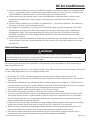
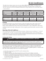
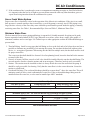
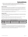
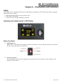
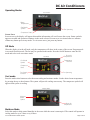
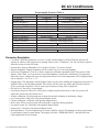
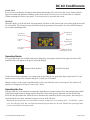
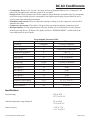
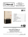
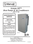
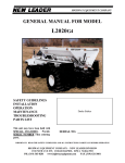
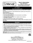
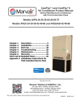
DC Air Conditioners
Self-contained
DC Air Conditioners
12 & 24 VDC
Models SMB05ACP (12 VDC) and
SMD14ACR (24VDC)
Owner’s & Installation Manual
SMB05ACP
SMD14ACR
Chapter 1: Safety Considerations.............................................................................2
Chapter 2: Routine Maintenance..............................................................................3
Chapter 3: General Description................................................................................5
Chapter 4: Installation Instructions..........................................................................6
Chapter 5: Thermostats and Controllers................................................................. 12
Chapter 6: Startup................................................................................................ 25
Chapter 7: Winterizing the System......................................................................... 26
Chapter 8: Troubleshooting................................................................................... 27
Chapter 9: Wiring Diagrams.................................................................................. 30
Chapter 10:Spare Parts List.................................................................................... 33
Chapter 11:Warranty............................................................................................. 34
Manufactured By:
Marvair® Division of AIRXCEL®, Inc.
P.O. Box 400 • Cordele, Georgia 31010
156 Seedling Drive • Cordele, Georgia 31015
Ph: 229-273-3636 • Fax: 229-273-5154
Email: [email protected]
www.marvair.com
12 & 24 VDC Owner’s Manual 8/2012
Marvair Marine UK
Unit B6 • Benridge Business Park • Holyrood Close
Poole, Dorset BH17 7BD.
+44 1202 650700
www.marvair.co.uk
Part #01514
8/2012
rev.4
Page
1 of 36
DC Air Conditioners
Chapter 1 – Safety Considerations
Congratulations on your purchase of a marine air conditioner by Marvair®. Your air conditioner has been
designed to provide years of safe, dependable operation. These instructions contain a general description on
the operation of the unit, how to set up thermostat, a list of routine maintenance items, basic trouble shooting
information, and the warranty. Installation of the air conditioner is also discussed.
The first thing we recommend for you to do is to write down the model and serial number of the unit. The
number can be found on the data label on the unit. Refer to them whenever you call upon your Marvair Marine
dealer regarding this unit.
Model No. ___________________ Serial Number___________________
Safety Considerations
This is the safety alert symbol . When you see this symbol on the Marvair Marine unit and in the instruction
manuals be alert to the potential for personal injury. Understand the signal word DANGER, WARNING and
CAUTION. These words are used to identify levels of the seriousness of the hazard.
DANGER
Failure to comply will result in death or severe personal injury and/or property damage.
WARNING
Failure to comply could result in death or severe personal injury and/or property damage.
CAUTION
Failure to comply could result in minor personal injury and/or property damage.
IMPORTANT is used to point out helpful suggestions that will result in improved installation, reliability or
operation.
!
DANGER
Self-contained units or evaporators of split systems should never be installed in engine rooms or other areas where fuel,
battery or bilge vapors may be introduced to the living quarters on board.
These components do not meet federal requirements for ignition protection. Do not install in spaces containing gasoline
engines, tanks, LPG/CPG cylinders, valves, fuel line fittings, or regulators. Failure to comply may result in injury or
death.
Do not terminate condensate drain line within four feet of any outlet of engine or generator exhaust systems, nor in a
compartment housing an engine or generator.
Installation and servicing of this system can be hazardous due to system pressure and electrical components. When
working on this equipment, always observe precautions described in the literature, tags and labels attached to the
unit(s). Follow all safety codes.
Marvair recommends that you use only factory certified, EPA licensed refrigerant technicians and
qualified marine electricians. ABYC certification in both HVAC and Marine electrical trades is desirable.
In receiving these certifications, a technician and his employer has made a statement of commitment to
professional, technically proficient and reliable service.
!
CAUTION
Certain components will run at fairly high temperatures. Exercise care in working around operating equipment. Do not
touch operating machinery without the aid of qualified personnel, as referred to above.
12 & 24 VDC Owner’s Manual 8/2012
Page 2 of 36
DC Air Conditioners
Chapter 2 – Routine Maintenance
Air Flow
Proper air flow is critical to the operation of the air conditioner. All grilles, both supply and return, must never
be blocked by objects such as bed linens, duffel bags, tackle boxes, etc.
Return Air Grille(s) and Filter(s)
Return air grilles are available in both aluminum and wood in standard configurations. They do not have
adjustable louvers and are available with and without filters. Return air filters should be cleaned regularly. The
filter shipped with your unit is located in front of the air coil can be cleaned with a vacuum cleaner or rinsed
with fresh water.
If your unit’s return air grille has a filter, be sure that your boat builder or installation technician has removed
the standard filter that comes with every unit in front of the evaporator (air) coil. Two filters can unduly restrict
air flow and in some cases, cause problems with performance. Use EITHER a return air filter grille or the
supplied filter, never both.
Depending upon the floor plan, your boat’s space constraints may dictate that a unit be installed in an area that
makes it difficult to access and clean the filter. If this is the case, and you do not have a return air filter grille,
you should consider removing the disposable unit filter and upgrading to a return air filter grille.
NOTE: Blocking the return air grille of neglecting filter cleaning will result in a restriction of air flow. After a
period of time, ice will form on the evaporator coil and a resultant LOW PRESSURE FAULT shutdown.
Figure 1. Filter can be cleaned with a vacuum cleaner.
Supply Air Grille(s)
Some installations will have more than one supply air grille. Standard main supply air grilles are generally made
of aluminum or wood frames with two or four-way adjustable louvers. These may be adjusted to direct air flow
from the grille to ensure a uniform cabin temperature. Main supply air grilles should never be closed at any time
while the unit is running. The secondary supply air grille more frequently will be a 4” (102mm) round plastic
design, but they can also be of the aluminum or wood frame standard configuration and are usually located out
of the main salon, galley, dinette area. These may, depending upon the style you or your boat manufacturer has
chosen, be closable. During the day, it may be closed should you like more air directed to the main living area.
Consult with your local Marvair Marine service representative if you are unsure which is the main supply grille
on your boat. Closing off the main supply air grille or secondary air grille, in some applications, may restrict air
flow and cause ice up of the evaporator.
12 & 24 VDC Owner’s Manual 8/2012
Page 3 of 36
DC Air Conditioners
Condensate Pan and Lines
The condensate and lines can develop an algae type growth. Periodic inspection and treatment with a mild
solution of bleach and water poured into the condensate pan will keep the condensate pan and lines clear.
Sea Water Strainer
The seawater strainer is available in several configurations – bronze or plastic. Yours has been sized in
accordance to system specifications for volume of water required. It is used to prevent debris such as eelgrass,
sea weed, leaves, etc., from passing through the system water lines and condensing coil. These items could
lodge themselves in the water supply causing several possible shutdown faults, and left unchecked, equipment
damage. Should the strainer become clogged or partially obstructed, adverse performance will be experienced.
The first indication will be a reduction in the quantity of the discharge water. Eventually , the high pressure
switch in the unit will activate and shut the unit down. (See Troubleshooting.) Turn the power off to the unit;
check strainer and pump, restart. (See Pump and Troubleshooting.)
To eliminate these potential problems, it is recommended that you check to make sure you have water flow each
time you turn the system on and clean your strainer weekly. More often as conditions dictate. In some regions, it
is common to experience a tremendous presence of jellyfish or sea nettles concentrated in back bay marinas for
short periods of time. These can clog strainers and water pumps every hour to hour and a half in some cases. In
such severe conditions, seek the advice of your local factory service representative. They will be most familiar
with solutions to localized situations. Marvair works closely with our servicing dealers when custom solutions
are required. During the warranty period, factory approval must be obtained for any modification to be done to
alleviate the problem without voiding warranty coverage.
Figure 2a. Unscrew and remove
Screen Housing
Figure 2b. Remove dirty Screen
Figure 2c. Rinse Screen with clean
water. Reinstallation is the reverse
of removal
Sea Water Pump
Your seawater pump has been sized in accordance with specifications for system water flow and volume.
A minimum flow rate of 1.5 GPM (5.69 LPM) for the SMB05 and 3.0 GPM (11.4 LPM) for the SMD14 is
required for proper operation. Always measure the flow rate at the inlet to the air conditioner. The pump is a
self priming.
Occasionally, sea grass, jellyfish and other items may pass through your strainer and get lodged in the pump
impeller. Should cleaning your strainer fail to eliminate a water flow problem, you should next check the pump.
First loosen the discharge line and gently remove it from the pump assembly. (Make sure the seacock is open.)
Water should rise above the pump to a level equal to the waterline of your boat. If not, there is a blockage.
12 & 24 VDC Owner’s Manual 8/2012
Page 4 of 36
DC Air Conditioners
Thermostat
A wall mounted thermostat/controller controls the operation of the Marvair air conditioner. The air temperature
sensor is located in the thermostat. Therefore, the thermostat should be placed to accurately measure the
temperature of the air in the room. Do not place the thermostat in direct sunlight. Make sure that the cool air
produced by the unit does not blow directly onto the thermostat.
Complete instructions for operating and configuring your thermostat can be found in Chapter 5.
Chapter 3 – General Description
The DC air conditioners built by Marvair® are self-contained, water-cooled units designed for use with either
fresh or seawater. They are designed to be used with a wall mounted thermostat and use R-134a refrigerant.
Operating Ranges
The air conditioner is designed to work over a wide range of conditions. Among the most important factors that
affect the performance of the unit are inlet water temperature, inlet (return) air temperature and the humidity of
the inlet (return) air. Please consult your Marvair Marine dealer or the factory if you have a question about the
operation of your air conditioner.
Electrical
The SMB model is designed to operate of a nominal 12 volt DC power supply - an inverter is not required. The
unit will operate on a DC voltage from 9 volts to 17 volts. The SMD14 is designed to operate on a nominal
voltage of 24 volt DC power supply. The SMD14 will operate on DC voltage from 21 to 28 volts.
General Operation
The air conditioners use R-134a refrigerant in a conventional vapor compression cycle to transfer heat from the
air in the boat to the water. In the cooling mode, a blower blows the cabin air through the indoor or evaporator
coil where it is cooled and dehumidified. Liquid refrigerant passing through the evaporator is boiled into a gas
by heat removed from the air. The warmed refrigerant gas enters the compressor where its temperature and
pressure are increased. The hot refrigerant gas travels to the water coil or condenser where it is cooled by the
water and condenses to a liquid. Liquid refrigerant is metered back into the evaporator coil to repeat the process.
High Pressure Switch
Located on the liquid refrigerant line, it is electrically connected to a lock-out relay which shuts the unit off if
the refrigerant pressure rises above the pressure set point (250 psig). This protects the air conditioner if water
flow is restricted.
The contacts on the high pressure switch close when the refrigerant pressure falls below the pressure set point
(150 psig). See Section, “Fail Safe & Fault Handling Modes’ in the thermostat/controller section for the o-LED
and o-Touch thermostats.
High Pressure
Opens
250
Closes
150
Figure 3. High Pressure Switch Settings
12 & 24 VDC Owner’s Manual 8/2012
Page 5 of 36
DC Air Conditioners
Compressor Time Delay
Prevents compressor from short cycling by delaying the compressor from starting whenever power is initially
applied to the air conditioner or whenever there is a call for cooling. The delay is 10-12 seconds after the fan
turns on.
Chapter 4 – Installation Instructions
Equipment Inspection
Concealed Damage
Inspect all cartons and packages upon receipt for damage during transit. Remove shipping cartons and boxes
and check for concealed damage. Important: Keep unit upright at all times.
Inspect refrigerant circuit for fractures or breaks. The presence of refrigerant oil usually indicates a rupture in
the refrigerant circuit.
Units that have been turned on their sides or upside down may have concealed damage to the compressor, other
components or to the refrigerant system. If the unit is not upright when you receive it, immediately file a claim
with the freight carrier for concealed damage and follow these steps:
1.
2.
3.
4.
Set unit upright and allow to stand for 24 hours with primary power turned OFF.
After 24 hours, connect power to unit.
Attempt to start the unit after 24 hours.
If the unit will not start or makes excessive noise, return the unit to the freight carrier.
Installation Requirements
!
WARNING
If the information in these instructions is not followed exactly, a fire, carbon monoxide poisoning or explosion may
result causing property damage, personal injury or loss of life • Read all instructions carefully prior to beginning
the installation. Do not begin installation if you do not understand any of the instructions. • Improper installation,
adjustment, alteration, service or maintenance can cause property damage, personal injury or loss of life. • Installation
and service must be performed by a qualified installer, service agency in accordance with these instructions and in
compliance with all codes and requirements of authorities having jurisdiction.
Location Requirements
●● Marvair self-contained air conditioners do NOT meet Federal requirements for ignition protection.
NEVER install the Marvair® air conditioner in an engine room, the bilge or any areas where it may
introduce deadly or noxious vapors into the boat’s living space. NEVER install the unit in any room or
compartment that contains an internal combustion engine, fuel tanks, LPG/CPG cylinders, regulators,
valves or fuel line fittings.
●● The condensate drain line MUST NOT terminate within three (3) feet of the exhaust of any engine or
generator nor any room that contains an engine or generator. Under some circumstances, carbon monoxide
can be pulled through the condensate tubing and introduced into the conditioned air.
●● It is recommended not to install the air conditioner above an electronic or electrical panel, circuit breakers
or anything electrical. If installed in this or an overhead location, a secondary drain pan should be used.
●● Select a location for noise considerations. Putting the unit under a bunk may not be desirable for sound
reasons. A better location may be at the bottom of a hanging locker. In some installations, acoustic baffles
may be required.
12 & 24 VDC Owner’s Manual 8/2012
Page 6 of 36
DC Air Conditioners
●● The unit must be installed in a space with sufficient clearance on all sides for proper air circulation and for
services. A minimum of three (3) inches must be provided from the face of the air coil to any obstruction,
wall or bulkhead. Sufficient air flow is critical to the proper operation of the unit.
●● Before placing the unit(s) into the space, make certain that there is sufficient room for all duct work,
condensate line connections, water in and out, electrical power connections and control power
connections.
●● The unit must be installed on level surface on a minimum of ½” plywood or equivalent. The condensate
line must, at all times, be lower than the base pan.
●● For optimum air circulation, it is good practice to install the supply air grilles near the top of the cabin
and the return air grille near the floor. This normally provides good circulation of the conditioned air
throughout the cabin. The location should provide easy access to the filter. If the filter is not readily
accessible, it probably will not be changed, shortening the life of the unit and operating at less than
designed performance.
●● To save space & facilitate installation, the Marvair air conditioner has a detachable electrical box. The box
can be mounted on the unit’s water connection side, the return air side, above the compressor or remote
from the unit.
Electrical Requirements
!
WARNING
Failure to follow safety warnings exactly could result in serious injury, death, and/or property damage.
Turn off electrical power at fuse box or service panel BEFORE making any electrical connections and ensure a proper
ground connection is made before connecting line voltage
All electrical work must meet the requirements of all applicable codes and ordinances. Work should only be
done by qualified persons.
If the wiring diagram that is on or was shipped with the unit is different from the one in this manual, refer to and
use the wiring diagram that is on or was shipped with the unit.
1. DC Wiring (12V or 24V) The power supply must have the proper voltage for the selected model.
a. Refer to the data label on the unit for field wiring requirements. The electrical data lists fuse and wire sizes for the unit.
b. Each unit has a Minimum Circuit Ampacity (MCA). Field wiring must be used that is of sufficient size to carry that amount of current. Use copper conductors only. Refer to the National Electrical Code for complete current carrying capacity data on the various insulation grades of wiring materials.
c. Power supply must be within allowable range of ±10% of rated voltage.
d. The unit must be properly grounded to reduce the risk of shock or electrocution.
e. A properly sized circuit breaker must be used. Information required to size the breaker is on the unit. The water pump does not require a separate breaker if there is only one air conditioner. However, the breaker must be sized for both the water pump and the Marvair unit. A separate breaker is required for the water pump if multiple Marvair units are installed.
f. Connections between the ship’s alternating current grounding conductor and the ship’s negative or bonding system must be made as part of the ship’s wiring as per ABYC standard E-11 or equivalent.
g. When servicing or replacing existing equipment that contains a chassis mounted ground lug, the service person or installed must verify the ship’s wiring for the connection required in item f. above.
h. All electrical connections must be made within the electrical junction boxes supplied with the unit. A terminal strip and/or electrical connectors are provided for component installation.
12 & 24 VDC Owner’s Manual 8/2012
Page 7 of 36
DC Air Conditioners
The tables below show the correct wire size to use with the SMD05 and the SMD14 air conditioners based
upon the one way wire length from the air conditioner to the breaker. The out and back is included in the
wire size. Do not use a wire size less that those shown below. Using a smaller wire size can cause the wire to
overheat and burn.
One way distance ft
(cm)
Wire Size
SMB05ACP Wire Size @ Various Distances
1'-6'
6'1" - 11'
11'1-18'
18'1"-28'
(1-183 cm) (184 - 335cm) (336-549 cm)
(550-853 cm)
#10
#8
#6
#4
One way distance ft
(cm)
Wire size
SMD14ACP Wire Size @ Various Distances
1' - 17'
17'1" - 26'
26'1 - 43'
43'1"- 67'
67'1"- 108'
(1-518 cm) ( 519 - 792 cm) (793 - 1,311 cm) (1,312 - 2,042 cm) (2,043 - 3,292 cm)
#8
#6
#4
#2
#1/0
Bonding
28'1"- 45'
(854 - 1,372 cm)
#2
Figure 4. Recommended Wire Size
To prevent corrosion due to stray electrical current or voltage, all metallic parts in contact with water must
be connected to the ship’s bonding system. This includes the air conditioner, all pumps, metallic valves,
fittings, strainers and thru-hulls. If any of these parts are isolated by PVC, vinyl, or rubber hoses, they must be
individually bonded to the ship’s bonding system. Failure to properly ground and bond the system may void the
warranty.
Mounting of the Air Conditioner
Select a surface that is firm and level, with sufficient clearances. Mount the unit on a minimum of ½” plywood
or equivalent. The unit will be secured to the surface with four hold down brackets. Secure the bracket with
suitable fasteners; e.g., lag screws. Note: To facilitate installation, the hold down fasteners may be installed after
all duct, water, condensate, and electrical connections are made.
Condensate Drains
!
WARNING CARBON MONOXIDE POISONING HAZARD
Failure to follow safety warnings could result in serious injury, death, or property damage.
The condensate drain line MUST NOT terminate within three (3) feet of the exhaust of any engine or generator nor any
room that contains an engine or generator. Under some circumstances, carbon monoxide can be pulled through the
condensate tubing and introduced into the conditioned air.
The stainless steel base pan has multiple openings for condensate drains. It is highly recommended that two
of the openings be utilized – one for back-up in case the other one becomes clogged or blocked. The other
openings should be sealed and plugged. The air conditioner can produce significant quantities of condensate that
may cause extensive damage to the vessel if not disposed of properly.
A. Select the two openings that will NOT be used for condensate lines.
B. Plug and seal them.
C. Install the condensate drain fittings through the base pan. Make sure the fitting is water tight.
D. Attach a 5/8” ID reinforced hose to the hose barb and secure with two stainless steel hose clamps.
E. Route the condensate hose down from the Marvair air conditioner to a sump or to an overboard fitting. If the drain runs overboard, it MUST NOT be within three (3) feet from the exhaust from the engine or generator. Double clamp all connections.
12 & 24 VDC Owner’s Manual 8/2012
Page 8 of 36
DC Air Conditioners
F. If the condensate line is run through a room or compartment containing an engine or fossil fueled device, it is imperative that the line be air tight to prevent carbon monoxide other any other hazardous gases or vapors from being introduced into the conditioned air system.
Sea or Fresh Water System
Proper water flow is absolutely critical to the operation of the Marvair air conditioner. If the pipe is too small,
back pressure is created causing a drop in water flow, even if the pump is correctly sized. If the piping is too
large, the slow velocity of the water may cause silt build-up and barnacle growth inside the piping, eventually
restricting water flow. See Table 1, Recommended Pipe Sizes and Table 2, Minimum Water Flow.
Minimum Water Flow.
The best material for sea water piping and fittings is cupronickel. Suitable materials for piping are hi-grade
bronze cupronickel and schedule 80 PVC pipe. Materials to avoid are yellow brass, copper, poor grades of
aluminum, stainless steel or steel pipe. Use Teflon® tape or other appropriate sealant on all threaded fittings to
prevent leaks.
1. Thru-hull fitting. Install a scoop-type thru-hull fitting as close to the keel and as far below the water line as possible to eliminate any possibility of air entering the system. Do not share the thru-hull with any other device; i.e., an engine or generator. When using one thru-hull for multiple units, the thru-hull must be sized for proper water flow.
The scoop-type thru-hull should face forward. On a fast planning board, locate the thru-hull at the transom to ensure water flow.
2. Seacock. A bronze, full flow seacock or ball valve should be installed directly onto the thru-hull fitting. The seacock must be closed to clean the strainer and in an emergency. Therefore, make it easily accessible.
3. Strainer. The strainer must be installed so that it is always below the water line and below the pump. It should be easily accessible for cleaning. Verify that the water flow is in the correct direction. Secure the strainer to a bulk head.
4. Overboard Discharge. The overboard discharge should be no more than 2” above the water line. This will minimize sound yet allow visual confirmation of water flow. If the overboard discharge fitting must be installed below the water line, a valve must be installed per ABYC standards.
Flow Rate (GPM)
1 through 4
Recommended Water Pipe Sizes
Pump Inlet Pipe Size
5/8”
Pump Discharge Pipe Size
5/8”
Table 1. Recommended Water Pipe Sizes
Minimum Water Flow* For Marvair Marine Self-Contained And Split Systems
Model
Minimum Water flow at the unit
SMB05
1.5 GPM / 5.7 LPM
SMD14
3.0 GPM / 11.4 LPM
*Based upon 85°F (29.5°C) inlet water measured at the inlet of the unit.
Table 2. Minimum Water Flow Chart
12 & 24 VDC Owner’s Manual 8/2012
Page 9 of 36
DC Air Conditioners
The Conditioned Air Duct & Grille System
!
WARNING CARBON MONOXIDE POISONING HAZARD
Failure to follow safety warnings could result in serious injury, death, or property damage. Do NOT operate in a
corrosive atmosphere containing chlorine, flourine or any other damaging chemicals which could harm the unit and duct
system, and permit spillage of combustion products into an occupied space.
Inadequate air flow is a leading cause of complaints and can significantly shorten the life of the unit, The air
distribution system must be engineered to ensure sufficient air flow throughout the system. This included proper
duct sizing and sufficient open area on the supply and return grilles.
Figure 5. Typical Air System Installation Schematic
Duct work guidelines
●● Duct work must be firmly attached, secured and sealed to prevent air leakage.
●● Use transition boxes and/or plenums with duct to split and route the conditioned air as required.
●● When using insulated flexible duct, make sure that the inner duct is secured and sealed to an adapter
before pulling the insulation over the connection
●● Install the supply air grilles high on the cabin wall to create good air circulation. Stretch the duct tight in
straight runs.
●● Make the bends and turns as large as possible. Secure the duct so that is remains in its installed position.
●● Always use insulated duct to prevent condensation.
●● Insulate all transitions and plenums.
12 & 24 VDC Owner’s Manual 8/2012
Page 10 of 36
DC Air Conditioners
●● If duct is in a storage or a high traffic area, protect it from being crushed by a shield or box.
●● If the duct must be run through areas containing engines or fossil fueled devices, it is absolutely
mandatory that the duct system be air tight to prevent carbon monoxide and any other hazardous gases or
vapors from being introduced into the conditioned air system.
Return Air Grilles
The return air grille should be located to ensure unimpeded air flow to the air coil on the air conditioner. The
grille may be located on the opposite the coil provided there is a space around the unit for sufficient air flow.
Maintain at least 4” between the grille and the Marvair® unit. For good air distribution throughout the cabin,
the return grille should be located near the floor when the supply grilles are high on the cabin wall. The return
air grille must have sufficient open air to permit adequate air to the indoor coil.
The Marvair air conditioner has a factory provided filter located in front of the air coil. If a return air filter grille
is used, it is recommended that the filter on the unit be removed.
Supply Air Grille
The supply air grille must have sufficient open area to permit adequate air flow. To prevent short circuiting of
the conditioned air, adjust the vanes of the supply grille so that the discharge air is not directed to the return air
grille or to the thermostat/controller.
The SMB05 air conditioner requires a supply grille with a minimum area of 12 sq. inches (e.g., a 4” round
grille). The duct should have a diameter of at least 4 inches and be no longer than 10 feet.
The SMD14 air conditioner requires a supply grille with a minimum area of 70 square inches.
Model
SMB05
SMD14
Nominal Air Flow
125 CFM
350 CFM
Air Flow, Grille and Duct Size
Minimum Size of Return Grille
70 sq. inches / 452 sq. cm
140 sq. inches / 903 sq. cm
Minimum Hose Size
4” / 10.2 cm
6” / 15.2 cm
Table 3. Air Flow, Grille and Duct Sizes
Air Flow Noise
Air moving through duct work and across the blades in the grilles and louvers generates sound. The faster
the air, the greater the sound. To keep sound to acceptable levels, the cross sectional area of the duct must be
large enough to keep the velocity below 600 ft/min (3m/sec). Air flow faster than this is likely to cause noise
complaints. The duct sizes in Table 3 are the minimum size required to deliver the proper air flow without
generating undue noise. Larger ducts will have less friction and less noise.
12 & 24 VDC Owner’s Manual 8/2012
Page 11 of 36
DC Air Conditioners
Chapter 5 – Thermostats and Controllers
SMB05
The SMB05 can be controlled by either the o-LED display or the Marvair 50176 thermostat. Before setting up
either thermostat or display:
1. Turn the seacock valve to the open position, and
2. Turn on the water pump.
3. Verify the water is being discharged overboard.
Operating and Configuring the o-LED Display
Before You Start:
1. Applying power:
When power is first applied, the display will show the software revision, and then return to the last mode the unit was in when power was removed.
On/Off Button
Mode Select
Button
Up Button
Fan Operation
Button
Down Button
2. Joystick operation:
The four position joystick may be tapped up, down, right, left or in the center to make changes to the operation of the control.
12 & 24 VDC Owner’s Manual 8/2012
Page 12 of 36
DC Air Conditioners
Operating Modes
Screen Saver
Room
Temperature
Cool Mode
Symbol
Fan Operating
Compressor Status
Screen Saver
In screen saver, the display will appear dim and the information will scroll across the screen. Status symbols
appear as needed and operation continues in the mode selected. Screen saver is activated after two minutes
without any button press in any mode. To exit screen saver, just press any button.
Off Mode
When the display is in the off mode, only the temperature will show in the center of the screen. Program mode
is accessed from this mode. The fan may be operated in this mode. Press the On/Off button to enter the ON
mode and select cool or moisture mode
Cool Mode
Room Air
Temperature
Temperature
Set Point
Cool Mode
Symbol
Compressor
Status
Fan Operating
Fan Speed
Indicator
Cool mode
Press the mode select button to select between cooling and moisture modes. Set the desired room temperature
by pressing the up or down button. The system will provide cooling as necessary. The compressor symbol will
appear when system is cooling.
Moisture Mode
Moisture
Mode
Symbol
Room Air
Temperature
Moisture Mode
Select this mode to help control humidity in the room while the room is unoccupied. The control will operate in
cooling mode for up to 1 hour every 6 hours.
12 & 24 VDC Owner’s Manual 8/2012
Page 13 of 36
DC Air Conditioners
Operating The Fan
The fan can be turned on while the system is off by pressing the fan button. See programmable parameters for
details on fan operation when the system is running.
Viewing Battery Voltage
In the ON mode, press and hold the mode select button for three seconds. The display will show the battery
voltage.
Air Sensor Trouble
If the air sensor in the display fails, AIR SENSOR TROUBLE will be displayed. If this happens, the display
must be repaired or replaced.
Programmable Parameters
Descriptions of programmable parameters, factory default values, and allowable values are shown in the table
below.
Entering The Program Mode:
To enter the program mode first put the unit in the off mode. Press the following sequence of buttons: Mode,
Up, Down, Mode. CYCLED FAN will appear as the first program parameter. Use the fan button to advance to
the next parameter and the mode button to go back to the last parameter. Use the up and down buttons to change
the parameters value. Exit the program mode when finished by pressing and releasing the On/Off button. The
program mode will exit to the off mode if no button is pressed for 60 seconds.
12 & 24 VDC Owner’s Manual 8/2012
Page 14 of 36
DC Air Conditioners
Description
Cycled Fan
System Units
Display Brightness
Screen Saver Brightness
Temperature Calibration
Staging Delay
Failsafe Level
Low Battery Detection
Voltage Calibration
Over Current Limit
Current Calibration
De-Ice Time
Use Option Sensor For
Pump Sentry
Reset Parameters
Programmable Parameter Table A
Default
Value
Continuous
Cycled or Continuous
°F
°F or °C
15
4=Minimum 15=Maximum
4
- and 1-8
0
Ambient +/- 10°F
15
5 to 135 Seconds
Not active or operational
10.6 VDC
Off, 8.6 to 11.9 VDC
System Voltage
0 to 25.5 VDC
Valid only with adapter board
Valid only with adapter board
Off
Off, 30 to 90 seconds
Valid only with adapter board
Valid only with adapter board
No
No or Yes
Parameter Description
○○ Cycled fan: When this parameter is set for “Cycled” and the display is in the ON mode, the fan will operate on whenever the compressor is running. When set for “Continuous”, the fan will always operate when the system is in the ON mode.
○○ System units: Degrees Fahrenheit (°F) or degrees Celsius (°C) can be selected
○○ Display brightness: Display brightness can be set from 4 to 15 to suit room lighting.
○○ Screen saver brightness: If set for (-) then a single bar will blink sequentially in the four corners of the display. Values from 1 to 8 can be set to suit room brightness. Temperature calibration: This parameter allows the user to calibrate the room air temperature sensor. The room temperature will be displayed and can be adjusted +/-10 °F or +/-5°C
○○ Staging delay: This parameter sets the length of time to wait before starting the compressor after power is applied if there is an immediate demand. The control will also wait one minute plus this time between cycles to start the compressor. This is used to prevent short cycling of the compressor.
○○ Fail safe level: Not active or operational.
○○ Low battery detection: When set, if the battery voltage remains below the set value, the system will follow the action set by the failsafe level.
○○ Voltage calibration: Use this parameter to adjust the internal voltmeter to the battery voltage.
○○ Over current limit: Valid only with optional adapter board.
○○ Current calibration: Valid only with optional adapter board.
○○ De-Ice time: When set, the system will perform the evaporator deicing program.
○○ Use option sensor for: Valid only with optional adapter board.
○○ Pump sentry: Valid only with optional adapter board
○○ Reset parameters: To reset all parameters to factory defaults, select YES and then exit the program mode by pressing the joystick center button. The display will show “EEPROM RESET”, and then show the room temperature in the off mode.
12 & 24 VDC Owner’s Manual 8/2012
Page 15 of 36
DC Air Conditioners
Figure 6. MasterFlux Wiring Diagram
Specifications
Set point range 55°F to 85°F
12.7°C to 29.4°C
Ambient temperature range displayed 5°F to 150°F
Sensor accuracy +/-2°F at 77°F
Line high voltage limit 15 VDC
Minimum operating temperature 0°F
Maximum operating temperature 180°F
Maximum RH conditions 95% Non condensing
Maximum length of the display cable 75 Feet
Maximum length for sensor cables 50 Feet
12 & 24 VDC Owner’s Manual 8/2012
Page 16 of 36
DC Air Conditioners
Operating and Configuring the 50176 Thermostat
!
CAUTION
This thermostat should be installed by trained technicians only. Adhere to all local and national codes. Disconnect all
power to the system before installing, removing, or cleaning.
Operation
The display indicates room temperature and the word ROOM is shown on the LCD. When in cool mode and
the temperature selector is pressed; the display temporarily indicates the setpoint temperature and the word
SET is shown on the LCD. Each time the UP arrow is pressed, the setpoint will increase. Each time the DOWN
arrow is pressed, the setpoint will decrease. Once the temperature selector button is no longer pressed for a few
seconds, the room temperature will again be displayed, and the word ROOM will be displayed on the LCD.
Temperature
Mode
ºF
90°F to 45°F
99°F to 32°F
Cooling (set)
Display (room)
Range
ºC
32°C to 7.0°C
38°C to 0°C
Note:
The temperature is displayed in degrees Fahrenheit as a factory set default . To display in degrees Celsius, see
“Configuration”.
There is a three-minute anti-short cycle delay time for cooling.
Refer to operation chart for a more detailed listing of operation sequence.
Application
The thermostat wiring must be a minimum of 18 gauge. The 50176 thermostat may also operate any 12 VDC
control circuit not exceeding 1 amp.
Operation Chart
The chart below shows the system functions with the 50176 thermostats. After the entire air conditioning system
is installed, check each position function.
Mode Switch
Cool
Fan Mode Switch
Auto
Fan Speed Switch*
Lo
Cool
Auto
Lo
3
4
Cool
On
Lo
Cool
On
Lo
5
6
Cool
Auto
Hi
Cool
Auto
Hi
7
8
Cool
On
Hi
Cool
On
Hi
1
2
9
Off
Auto
10
Off
On
11
Off
On
*Note: There is only one fan speed on the SMB05.
12 & 24 VDC Owner’s Manual 8/2012
Lo or Hi
Hi
Hi
Calling
No
Yes
1° above set
No
Yes
1° above set
No
Yes
1° above set
No
Yes
1° above set
Operation of Unit
No functions occur in this mode
GL-FAN (Gray), Y-Compressor
(Yellow) energized
GL-FAN (Gray) energized
GL-FAN (Gray), Y-Compressor
(Yellow) energized
No functions occur in this mode
GH-FAN (Green),
Y-Compressor (Yellow) energized
GH-FAN (Green) energized
GH-FAN (Green),
Y-Compressor (Yellow) energized
No functions occur in this mode
GL-FAN (Gray) energized
GH-FAN (Green) energized
Page 17 of 36
DC Air Conditioners
Installation
!
WARNING
Be sure all electrical power has been disconnected from the air conditioner and the power supply.
These instructions are provided for the proper mounting of the thermostat itself. An Operation Chart is provided
to show thermostat capabilities.
A. THERMOSTAT LOCATION
This thermostat is a sensitive instrument. For accurate temperature control and comfort, the following
considerations should be taken into account:
1.Locate the thermostat on an inside wall about five feet above the floor. Pick a dry area where air circulation is good.
2. Do not install the thermostat where there are unusual heating conditions such as direct sunlight, heat producing appliances (television, radio, wall lamp, etc.) or a furnace or air conditioner supply register.
B. WIRING THE WALL THERMOSTAT
The OEM must supply the stripped wires to mate per Figure 7. The wires must be connected by wire nuts to
wiring harness before the base is secured to the wall.
Figure 7. Wiring the Wall Thermostat
C. ATTACHING THE WALL THERMOSTAT
1.Separate the thermostat cover from the base by gently pulling at the top corner.
2. Connect wires to the wiring harness.
3. Attach the new thermostat base to the wall at the desired mounting location.
4. Reattach thermostat cover to base.
Configuration Mode
The configuration mode is used to set the 50176 to match your system.
To configure the 50176, perform the following steps:
1. Verify the 50176 is in the OFF mode.
Slide the mode switch to the right position until off mode displays.
2. Remove the cover of the thermostat by gently pulling near one of the corners at the top of the thermostat.
3. Press both the LEFT and RIGHT switches for 1 second while the 50176 is in OFF mode.
12 & 24 VDC Owner’s Manual 8/2012
Page 18 of 36
DC Air Conditioners
Press the up or down button to change settings within each screen.
Press the RIGHT switch to advance to the next screen.
Note: Pressing the LEFT switch will return you to the previous screen.
To exit configuration mode, press both the LEFT and RIGHT switches for 1 second or slide the mode switch to
cool.
Configuration Mode Settings
The setup screens for Configuration Mode are as follows:
1. Temperature Scale (F or C) – Choose Fahrenheit or Celsius.
Press the up or down button to select.
Press the RIGHT switch to advance to the next screen.
2. Temperature Differential (1°F to 5°F) (1°C to 3°C) – Set the number of degrees between your “setpoint” temperature and your “turn on” temperature.
Press the up or down button to set differential value.
Press the RIGHT switch to advance to the next screen.
3. Lockout (0°F-8°F) (0°C-8°C) – Select the number of degrees set temperature can be changed during keypad lockout
Press the up or down button to select.
Press the RIGHT switch to advance to the next screen.
4. Minimum Cool Setpoint (45°F to 90°F) (7°C to 32°C)
Adjust to control the minimum cool set temperature allowed.
Press the up or down button to select.
Press the RIGHT switch to advance to the next screen.
IMPORTANT: DO NOT SET THE MINIMUM COOL SET POINT BELOW 68°F (19°C).
5. Room Temperature Offset (+9°F to -9°F) (+5°C to -5°C)
Adjust to calibrate displayed room temperature to match actual room temperature.
Press the up or down button to select.
Press the RIGHT switch to advance to the next screen.
6. Maximum Cycles Allowed Per Hour (- -, 2-6)
- - = as many as needed, 2-6 = maximum cycles/hour
Press the up or down button to select.
Press the RIGHT switch to advance to the next screen.
Marvair recommends a setting of “as many cycles as needed”
To exit configuration mode, press both the LEFT and RIGHT switches for 2 seconds or slide the mode switch to
cool.
12 & 24 VDC Owner’s Manual 8/2012
Page 19 of 36
DC Air Conditioners
SMD14
The SMD14 is controlled by the o-Touch display.
Operating and Configuring the o-Touch Display
Before setting up either thermostat or display:
1.Turn the seacock valve to the open position,
2.Turn the water pump on, and
3.Verify the water is being discharged overboard.
Introduction:
When connected to a 12-24VDC controller, the versatile o-Touch DC digital display provides room temperature
control and humidity reduction in a small package. It allows for easy control of fan speed, operating mode and
temperature in a wide variety of applications.
Features include:
○○ Easy touch screen operation.
○○ Built in room temperature sensor.
○○ The display is compatible with Vimar and Gewiss frames.
○○ Visual symbols enable the viewer to see the operating status at a glance.
○○ Easily programmed for customized operation.
○○ Both automatic and manual six level fan speed control.
○○ De-icing cycle to prevent evaporator icing.
○○ Automatic moisture mode provides relative humidity control.
○○ Variable compressor speed control reduces power consumption as ambient temperature approaches the set point.
○○ Compressor current limiting can be used to prolong battery life.
Operation
Applying Power
When power is first applied, the display will show the software revision, and then return to the last operating
mode the unit was in when power was removed.
12 & 24 VDC Owner’s Manual 8/2012
Page 20 of 36
DC Air Conditioners
Screen Saver
In screen saver, the display will appear dim and the information will scroll across the screen. Status symbols
appear as needed and operation continues in the mode selected. Screen saver is activated after two minutes
without touching the screen in any mode. To exit screen saver, just touch the screen.
Off Mode
When the display is in the off mode, the temperature will show in the center of the screen along with the fan and
on / off symbol. The fan may be operated in this mode by pressing the fan symbol. Press the On/Off button to
access other operating modes.
Operating
Mode Icon
Temperature
Set Point
ON/OFF
Icon
Room Air
Temperature
Fan
Operating
Fan Speed
Indicator
Built-in Room
Temperature Sensor
Operating Modes
Two operating modes are available and can be changed by pressing the symbol in the upper left corner. The
symbols below will appear in the upper left on the display.
Moisture Mode Symbol
Cool Mode Symbol
Set the desired room temperature in cooling mode by pressing the set point in the upper right corner. Use the
arrows to raise or lower the set point and press X when you are finished.
Moisture mode is used to help control humidity in the room while the room is unoccupied. The control will
operate in cooling mode for up to 1 hour every 6 hours.
Operating the Fan
Fan speed may be set for automatic (temperature dependent) or manual control. Press the fan operating symbol
in the bottom right corner to change speeds. Manually selected fan speed is indicated with the M showing
before the fan speed indicator. When the fan is automatically controlled, the M is not present. The fan may be
controlled in the cool, heat, automatic modes as well as in the off state.
Manual fan speed operation is not available when the compressor is not running if the “Cycled Fan” option is set. Turn the unit off in this case and then manual fan operation may be used. Manual fan speed operation is also not available in moisture mode.
12 & 24 VDC Owner’s Manual 8/2012
Page 21 of 36
DC Air Conditioners
Viewing System Status
System
Voltage
System
Current
Motor
Current
Motor
Temperature
Motor
Speed
Several system operating parameters can be viewed during operation as shown above. Press and hold the lower
center of the display (where the fan speed indicator is located) to view this status. To exit the status view, press
anywhere on the display.
The system current is available at all times, the remaining items only during compressor operation.
Failure Messages
The following fault messages will be shown on the display in the event of a failure:
AIR SENSOR TROUBLE: Failure of the display mounted air sensor.
MASTERFLUX GENERATED ERRORS: Errors generated by the Masterflux controller will also show on the
display. The exact text of these errors is dependent on the connected controller. See the operating manual for
your Masterflux controller for details and resolution of these errors.
Programmable Parameters:
Program Mode
To enter the program mode first put the unit in the off mode. Then press and hold the On / Off symbol for 3
seconds. Press the right arrow to advance to the next parameter and press the left arrow to go back to the last
parameter. Press the up or down arrows to change the parameters value. Exit the program mode when finished
by pressing the X or wait 60 seconds for the display to exit.
Parameter Description:
○○ Cycled fan: When set for “Cycled”, the fan will operate on demand. When set for “Continuous”, the fan will always operate when the system is in cool mode.
○○ System units: Degrees Fahrenheit (°F) or degrees Celsius (°C) can be selected
○○ Display brightness: Display brightness can be set from 4 to 15 to suit room lighting conditions.
○○ Screen saver brightness: If set for (0) then a single bar will blink sequentially in the four corners of the display. Values from 1 to 8 can be set to suit room lighting conditions.
○○ Temperature calibration: This parameter allows the user to calibrate the room air temperature sensor. The room temperature will be displayed and can be adjusted +/-10 °F or +/-5°C
○○ Staging delay: The compressor staging delay is provided for multi system installations. Set the Staging delays at different intervals so only one compressor starts at a time when power is applied.
○○ De-Ice Time: If the compressor runs continuously for longer than one hour, the compressor will shut down and the blower will run for the specified time. The compressor will then restart and resume operation.
12 & 24 VDC Owner’s Manual 8/2012
Page 22 of 36
DC Air Conditioners
○○ Cycled pump: When set for “Cycled”, the pump will run on demand. When set for “Continuous”, the pump will run continuously when the system is in cool mode.
○○ Fan speed 1-6: These parameters are used to optimize fan performance and airflow Speed 1 corresponds to the lowest speed setting. Speed 6 corresponds to the highest speed setting. Speeds should be set to avoid system icing in humid environments.
○○ Maximum comp current: Thirty seconds after starting a cooling cycle the compressor current will be limited to this value.
○○ Compressor speed range: The number of degrees from set point to maximum compressor speed.
○○ Reset parameters: To reset all parameters to factory defaults, select YES and then exit the program mode by pressing the on / off button. The display will show “EEPROM RESET”, and then show the room temperature in the off mode.
Description
Cycled Fan
System Units
Display Brightness
Screen Saver Brightness
Temperature Calibration
Staging Delay
De-Ice Time
Cycled Pump
Fan A Speed 1
Fan A Speed 2
Fan A Speed 3
Fan A Speed 4
Fan A Speed 5
Fan A Speed 6
Compressor Speed Range
Maximum Comp Current
Reset Parameters
Programmable Parameter Table
Default
Value
Continuous
Cycled or Continuous
°F
°F or °C
15
4=Minimum 15=Maximum
4
- and 1-8
0
Ambient +/- 10°F
15
5 to 135 Seconds
2
1 - 5 Minutes
Cycled
Cycled or Continuous
30
30-90
35
30-90
40
30-90
45
30-90
55
30-90
85
30-90
2 (1.1)
2-5 °F (1.1-2.8 °C)
35
Off, 10-60 Amps
No
No or Yes
Specifications
Set point range
55°F to 85ºF
12.7°C to 29.4°C
Ambient temperature range displayed
5°F to 150°F
-15°C to 65.6°C
Sensor accuracy
+/-2°F at 77°F
+/-1.1°C at 25°C
12 & 24 VDC Owner’s Manual 8/2012
Page 23 of 36
DC Air Conditioners
Evaporator Output MAX
10 Amps
Condenser Output MAX
10 Amps
System Current MAX
60 Amps
Minimum operating temperature
0°F
17.8°C
Maximum operating temperature
180°F
82.2°C
Maximum RH conditions
95% Non-condensing
Maximum length of the display cable 75 Feet
22.86 m
Note: The wires to the blower, to the MasterFlux controller and to the harness connections to the MasterFlux controller are factory installed.
12 & 24 VDC Owner’s Manual 8/2012
Page 24 of 36
DC Air Conditioners
Chapter 6 – Start-Up
1. Turn the seacock valve to the open position.
2. There is a short delay on starting.
3. If the water pump has a dedicated breaker, turn it on. Verify that water is being discharged overboard.
4. Turn on the circuit breaker to the Marvair unit.
5. Refer to the operating instructions in this manual for your thermostat/controller and set the system for cooling by using the display module or the thermostat.
6. Adjust the cooling temperature set point on the display module or the thermostat higher than the cabin temperature.
7. Slowly lower the thermostat’s cooling set point until the set point is below the cabin temperature. The blower, compressor and pump should be operating.
8. Close all doors and hatches.
9. Allow the unit to operate 10 minutes.
10.After 10 minutes, there should be a 15°F (8°C) to 20°F (9°C) difference in the supply and return air
temperatures.
Operation Checklist
1.
2.
3.
4.
5.
6.
Verify that all tie downs clamps have been correctly installed.
Make sure all electrical cover plates are in place.
Test for continuity between the ground and the boat’s bonding system or the engine’s DC negative connection.
Make sure that there are zero volts between the boat’s ground and the ground in the air conditioner with the unit operating.
Check all water hoses for leaks.
Make certain that poisonous gases or noxious fumes are NOT being introduced into the vessel via the HVAC system.
7. Check for proper condensate drainage.
12 & 24 VDC Owner’s Manual 8/2012
Page 25 of 36
DC Air Conditioners
Chapter 7 – Winterizing the System
There are two scenarios for winterizing the system – the boat remains in the water or the boat is
out of the water, in dry dock storage. Please follow the procedures described below for your situation.
Boat remains in the water
In water storage requires the use of a potable anti-freeze solution throughout the system’s water supply and
discharge lines. Be sure to follow all state, local and federal ordinances before discharging an anti-freeze
solution overboard.
1. Close ball valve.
2. Disconnect water line at ball valve.
3. Insert line into a bucket of potable anti-freeze.
4. Run air conditioner until a solid stream of anti-freeze is being discharged overboard.
5. Reconnect water line at ball valve.
Boat is out of water in dry dock
With the boat out of the water:
1. Open the seacock to permit all the water to drain out of system via the thru-hull fitting.
2. Remove and empty the seawater strainer basin.
3. Loosen the screws on the pump head to allow the water to drain from the pump and from the water line between the pump and strainer.
4. Close the seacock.
When the boat is put back into the water in the spring:
1. Gradually open the seacock to allow water to fill the system to the level of the pump.
2. Tighten the pump face to achieve a seal.
3. Open the seacock valve completely.
12 & 24 VDC Owner’s Manual 8/2012
Page 26 of 36
DC Air Conditioners
Chapter 8 – Troubleshooting
Troubleshooting the SMB05 and SMD14 Air Conditioners
PROBLEM/SYMPTOM
The unit does not
operate.
(Nothing works at all)
Unit has power, but
display/controller is
inactive.
Blower runs but
compressor does not
start
LIKELY CAUSE(S)
1. Power supply problem
(Low voltage)
CORRECTION
1. Check voltage at power supply and at the
electrical box. Min voltage should be >90% of
rating. Check wiring to unit and at shore, boat and
unit (if applicable) breakers or fuses. Check shore
power connections at battery and at unit.
2.Tripped breaker/disconnect.
2.Check circuit protection devices for continuity.
3. Display/Controller
3.Setpoint may be too high; check unit and reset.
Thermostat may be out of calibration or otherwise
defective. Also check for loose connection(s).
1. If connections are good, control may be faulty.
Replace.
1.Check interface cable
connections
1. Power supply problem.
2. Display/Controller.
3. Safety switches are
tripping out unit
4. Loose or defective wires
5. Compressor
6. Refrigerant leakage or
loss
7. Control board
8. Low amps
12 & 24 VDC Owner’s Manual 8/2012
1. Check voltage at power supply and control box.
Check for loose wires. Voltage must be within
10% of rated nameplate voltage.
2. Check the display/controller and unit for loose
wires. Secure any loose connection. Fan is
typically programmed to run with the compressor.
Adjust set points or reset defaults. Make sure
thermostat is not in FAN ONLY mode. The
thermostat should be replaced if defective.
3. Check for water flow. Check for proper air flow.
Check refrigerant charge. Check switches for
loose wire connection, broken or burned contacts.
4. Check for loose wires connections. Replace
terminals if they are loose or weak.
5. Check for power to compressor on PC board.
Check for electrical shorts, ground and open
circuits.
Replace compressor if defective.
6. Locate leak(s), reclaim, repair, evacuate and
recharge unit with refrigerant.
7. Verify that power is being provided from the
control board. Replace control board if it is
defective
8. Load test batteries to make sure they are fully
properly charged.
Page 27 of 36
DC Air Conditioners
PROBLEM/SYMPTOM
Compressor runs, but
blower will not run.
LIKELY CAUSE(S)
1. Blower motor.
2. Power supply problem.
3. Control board
Unit trips off on high
pressure but pump is
running
Water pump does not
run.
Low air flow
Low water flow
Unit provides
insufficient cooling
1. Low water flow to the
condenser
2. Pump is air locked
1. Compressor is
off and the pump is
programmed to run with
the compressor.
2. No power to pump at
control board.
3. Faulty pump
1. Dirty filter.
2. Return air flow blocked.
3. Louvers in grille closed.
4. Fan speed set too low
1. Restriction or blockage
in waterline.
2. Air lock in pump
1. Restriction in water
system.
2. Water pump defective/
undersized.
3. Air filter.
4. Indoor coil.
5. Ice on indoor coil
6. Unit is undersized
7. Low refrigerant
12 & 24 VDC Owner’s Manual 8/2012
CORRECTION
1. Check for electrical shorts, ground and open
circuits. Replace blower motor if it is defective.
2. Check voltage at power supply. Voltage at unit
must be within 10% of rated nameplate voltage
3. Verify that power is being provided from the
control board. Replace control board if it is
defective
1. Check water lines to the unit for kinks in line.
Check strainer and thru hull for obstructions.
Clean as required. Verify seacock (ball valve) is
open. Check for obstruction in the pump and
remove
2. Purge air from system
1. Adjust room set point to call for cooling.
That will bring the water pump and compressor
on.
2.Control board may be faulty
3. Replace pump.
1. Clean filter.
2. Remove obstruction.
3. Open louvers.
4. Raise fan speed if in Manual or set to Auto.
1. Clean raw water strainer. Clean thru hull. Make
sure valve is open. Clean pump.
2. Open ball valve, remove discharge hose and
open valve to bleed air from the pump. Check
pump’s impellor for wear or debris
1. Strainer or thru-hull fitting are clogged. Clean and
check for water flow. Make sure seacock (ball
valve) is open
2. Check for electrical shorts, ground and open
circuits. Replace water pump if it is defective.
Replace water pump if it is undersized
3. Clean or replace the air filter if it is dirty.
4. The indoor coil may require cleaning if the unit
was operated without a filter.
5. Thermostat setting is too low. Shut down unit until
ice has melted and restart at a higher
temperature setting. Check to see if filter is dirty
or long or restricted ductwork.
6. Check if the unit is undersized for the load.
Replace with larger unit or add additional unit(s) if
necessary
7. Add refrigerant
Page 28 of 36
DC Air Conditioners
PROBLEM/SYMPTOM
Loud operation.
LIKELY CAUSE(S)
1. Copper tubing is
vibrating.
2. Indoor blower
assembly
Water is leaking from
unit
Electrical shock at unit.
3. Loose cabinet or
components.
4. Improper unit
installation
1. Condensate pan.
2. Condensate drain line
or pump.
3. Loose fittings or
connections
1. Electrical component is
shorted to ground
12 & 24 VDC Owner’s Manual 8/2012
CORRECTION
1. Adjust by bending slightly to a more stable
position. Separate any tubing that is making
contact with other tubing or components.
2. If blower wheel is hitting housing, adjust the wheel
position in the housing. Replace blower motor or
assembly if the bearing(s) are defective.
3. Check and tighten loose screws
4. Make sure unit is level and secure to deck.
1. Check for leaks and repair as required.
2. Check for leaks and repair as required.
3. Tighten fittings and connections. Check the
condensate drain line for leaks
1. Check control board, blower motor, compressor
and pumps with an ohmmeter or high potential
tester. Determine what is grounded and replace or
rewire.
Page 29 of 36
DC Air Conditioners
Chapter 9 – Wiring Diagrams
12 & 24 VDC Owner’s Manual 8/2012
Page 30 of 36
DC Air Conditioners
12 & 24 VDC Owner’s Manual 8/2012
Page 31 of 36
DC Air Conditioners
12 & 24 VDC Owner’s Manual 8/2012
Page 32 of 36
DC Air Conditioners
Chapter 10 – Spare Parts List
SMB05ACP Recommended Spare Parts
Marvair Part Number
Compressor
10343
Control Module
01627
Evaporator Coil
60127
Motorized Impeller (Blower)
40116
Control Board
50196
Condenser (water coil)
60194
High Pressure Switch
70339
Cap Tube/Strainer Assembly
20419
Filter
91916
Low Voltage Harness Assembly
01678
VDC Power Harness Assembly
01679
SMD14 Recommended Spare Parts
Marvair Part Number
Compressor 24 to 48VDC
10377
Coil Indoor, Black
60181
Controller, Digital
Motorized Impeller 24V (Blower)
Board, Control 12/24 VDC Interface
Heat Exchanger, Coaxial, Black
High Pressure Switch R134A, 250 Open/150 Close
Capillary Tube Assembly
Filter 13¼” x 11-5/8” x 1/4” PERMACOOL
Harness, Low Voltage DC 4 PIN
Harness Low Voltage DC 8 PIN
VDC Power Harness
12 & 24 VDC Owner’s Manual 8/2012
70593
40157
92211
60193
70339
S/09088
92150
01928
01930
01679
Page 33 of 36
DC Air Conditioners
Chapter 11 – Warranty
Marvair® Marine Self-Contained and Split Systems Warranty
Parts
If any part of your Marvair unit fails because of a manufacturing defect within twenty-four months from the
date of purchase of a new boat or within twenty-four months from the date of installation of the air conditioner,
but not to exceed thirty-six from the date of manufacture by Marvair, Marvair will furnish without charge, EXW
Cordele, Georgia, the required replacement part.
Labor
If any part of your Marvair reverse cycle air conditioner or air conditioner fails because of a manufacturing
defect within twenty-four months from the date of purchase of a new boat or within twenty-four months from the
date of installation of the air conditioner, but not to exceed thirty-six from the date of manufacture by Marvair,
Marvair will pay for the related service labor to replace the failed part according to the Marvair Flat Rate Schedule
currently in effect. The owner must provide proof of the date of the purchase of the boat or date of installation of
the Marvair unit. The owner’s registration card filed with Marvair, the invoice for the purchase of the vessel, an
invoice for the installation of the unit, or similar documents are examples of proof of the date.
When service is required, it must be performed during normal working hours (8:00 a.m. to 5:00 p.m.) Monday
through Friday and must be performed by Marvair personnel or their designated Service Representative.
The responsibility of the Owner of the Equipment includes the following:
1. To operate the equipment according to the manufacturer’s instructions.
2. To provide easy accessibility for service.
3. To check and reset circuit breaker(s) and disconnect before calling for service. (Circuit breaker(s)
may be in the main service panel.)
4. To keep the unit clean and free of dirt.
5. To clean and/or replace the filter as required. (The filter may be located in the return air filter grille or
in front of the evaporator coil.)
6. To keep the evaporator coil clean and the condenser coil free of sediment or scale.
7. To pay the charges incurred when any of the above have not been done.
8. To pay for repair or replacement of any material or part other than those within the Marvair unit or
thermostat itself.
9. To check any fuses on the circuit board and replace as required.
The owner of the product may ship the allegedly defective or malfunctioning product or part to Marvair, at
such owner’s expense, and Marvair will diagnose the defect and, if the defect is covered under this warranty,
Marvair will honor its warranty and furnish the required replacement part. All costs for shipment and risk of loss
during shipment of the product or part to Marvair and back to the owner shall be the responsibility and liability
of the owner. Upon request by an owner, Marvair may arrange for remote diagnosis and repair of the allegedly
defective or malfunctioning product or part.
An owner requesting performance under this Warranty shall provide reasonable access to the allegedly
defective or malfunctioning product to Marvair and its authorized agents and employees.
12 & 24 VDC Owner’s Manual 8/2012
Page 34 of 36
DC Air Conditioners
This warranty does not cover damage caused by improper installation including any refrigerant leaks in
the tubing and fittings between the evaporator and condenser sections on split systems; misuse of equipment;
negligent servicing; damage due to use of the product for purposes other than those for which it was designed;
damage caused by natural disasters, power surges, lightning and submersion; damage caused by unauthorized
modifications; and damage caused by improper wiring or power supply to the air conditioner including operating
the unit with an undersized generator.
THIS WARRANTY AND SERVICE POLICY CONSTITUTE THE EXCLUSIVE REMEDY OF ANY
PURCHASER OF A MARVAIR REVERSE CYCLE AIR CONDITIONER AND IS IN LIEU OF ALL
OTHER WARRANTIES, EXPRESSED OR IMPLIED, INCLUDING, WITHOUT LIMITATION, ANY
IMPLIED WARRANTY OF MERCHANTABILITY OR FITNESS FOR USE, TO THE FULLEST EXTENT
PERMITTED BY LAW. IN NO EVENT SHALL ANY IMPLIED WARRANTY OF MERCHANTABILITY
OR FITNESS FOR USE EXCEED THE TERMS OF THE APPLICABLE WARRANTY STATED ABOVE
AND MARVAIR SHALL HAVE NO OTHER OBLIGATION OR LIABILITY. IN NO EVENT SHALL
MARVAIR BE LIABLE FOR INCIDENTAL OR CONSEQUENTIAL DAMAGES OR MONETARY
DAMAGES.
THIS WARRANTY GIVES YOU SPECIFIC LEGAL RIGHTS, AND YOU MAY ALSO HAVE OTHER
RIGHTS WHICH VARY FROM STATE-TO-STATE. Some states do not allow limitations or exclusions, so the
above limitations and exclusions may not apply to you.
5/09 Rev. 5
12 & 24 VDC Owner’s Manual 8/2012
Page 35 of 36
DC Air Conditioners
Notes
12 & 24 VDC Owner’s Manual 8/2012
Page 36 of 36