1
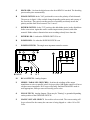
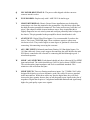
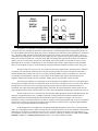
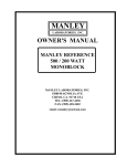
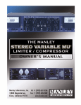
MANLEY
LABORATORIES, INC.
OWNER'SMANUAL
MANLEY REFERENCE
DIGITAL TO ANALOGUE
CONVERTER
MANLEY LABORATORIES, INC
13880 MAGNOLIA AVE.
CHINO, CA. 91710
TEL: (909) 627-4256
FAX: (909) 628-2482
emanley@ netcom.com
http://www.manleylabs.com
CONTENTS
SECTION
PAGE
INTRODUCTION
3
MAINS CONNECTIONS
4
FIGURE 1
FRONT PANEL
5
FIGURE 2
REAR PANEL
6
INTERNAL
8
WARRANTY
10
WARRANTY REGISTRATION
11
INTRODUCTION
THANK YOU!...
for choosing the Manley Laboratories REFERENCE 20 BIT DIGITAL TO ANALOGUE
CONVERTER. Please read over this manual carefully as it contains information essential to
proper operation of this unit.
The MANLEY DIGITAL TO ANALOGUE CONVERTER features completely dualmono analogue sections and power supplies. The digital board features the only 20-BIT, 128x
oversampling converter unit available today, custom made for us by ULTRAANALOG. The
128x oversampling rate at which the ULTRAANALOG operates eliminates the need for steep
anti-alias filters, and eliminates differential non-linearity and harmonic distortion for low
amplitude signals. The ULTRAANALOG AES-21 chip effectively removes incoming jitter
from the digital inputs. This monolithic device contains 2 separate precision phase-locked loops
- the first is digital and removes higher frequency jitter, the second is designed to remove any
remaining jitter. Unlike earlier AES / EBU / SPDIF interfaces that allowed only 16 or 18 bits
through this device allows up to 24 bits through. The only digital processing used is the HDCD
® filter chip. Not only does it provide the path for HDCD ® recordings it is also the best
performing digital filter available. For maximum fidelity and musical involvement the line
amplifier is all tube differential input / totem output vacuum tube design with both balanced
and unbalanced outputs available.
LOCATION & VENTILATION
The MANLEY DIGITAL TO ANALOGUE CONVERTER must be installed in a stable
location with ample ventilation. It is recommended, if this unit is rack mounted, that you allow
enough clearance on the top and bottom of the preamp such that a constant flow of air can flow
through the ventilation slots.
WATER & MOISTURE
As with any electrical equipment, this unit should not be used near water or moisture.
If liquid enters the unit, it must be immediately returned to your dealer for servicing.
SERVICING
The user should not attempt to service this unit beyond that described in the owner's manual.
Refer all servicing to Manley Laboratories.
WARNING!
!
TO PREVENT THE RISK OF ELECTRIC SHOCK
DO NOT OPEN THE CABINET
REFER SERVICING TO
QUALIFIED PERSONEL
MAINS CONNECTIONS
Your unit has been factory set to the correct mains voltage for your country. The voltage
setting is marked on the serial badge, located on the rear panel. Check that this complies
with your local supply.
Export units for certain markets have a moulded mains plug fitted to comply with local
requirements. If your unit does not have a plug fitted the coloured wires should be connected to the appropriate plug terminals in accordance with the following code.
GREEN/YELLOW
BLUE
BROWN
EARTH
NEUTRAL
LIVE
terminal
terminal
terminal
As the colours of the wires in the mains lead may not correspond with the coloured marking
identifying the terminals in your plug proceed as follows;
The wire which is coloured GREEN/YELLOW must be connected to the terminal in the
plug which is marked by the letter E or by the safety earth symbol or coloured GREEN or
GREEN and YELLOW.
The wire which is coloured BLUE must be connected to the terminal in the plug which is
marked by the letter N or coloured BLACK.
The wire which is coloured BROWN must be connected to the terminal in the plug which is
marked by the letter L or coloured RED.
DO NOT CONNECT/SWITCH ON THE MAINS SUPPLY UNTIL ALL OTHER
CONNECTIONS HAVE BEEN MADE.
FRONT PANEL CONTROLS
A
B
C D
E
FG
H
I
J K
L
A
DIGITAL INPUT SELECT: Selects any of the 4 digital inputs. Positions 1, 2
and 3 correspond to the RCA phono style S/PDIF and the XLR AES / EBU inputs.
Position 4 corresponds to the A.T.&T. Optical input. When the switch is changed
the output mutes until "VALID DATA" is "LOCKED" by the AES 21 jitter
reduction chip.
B
32, 44.1, 48: 3 red LEDs that indicatethe sample rate of the incoming data. CD's
are always 44.1 while the sample rate of DAT's may be any of the three.
C
VALID DATA LED: Lit when the unit has a readable input that can be converted
to audio. This immediately indicates a "good" input
D
ERROR LED: Lit when audio is muted. There are several conditions that will
cause this. 1) Warm - up timer approximately 30 seconds. 2) momentary loss of
data including changing the DIGITAL INPUT SELECT. 3) any cable related loss
of data, unreadable data or data errors. 4) The phase-locked loop has not yet locked
or electronic latch-up. If the converter has been on for over a minute and the LED
is lit the problem can usually be remedied best by powering off the converter for
10 seconds and powering up again.
E
VOLUME: This is a precision 4 stack stepped attenuator. Because some users
prefer to feed the outputs of this unit directly to their power amps this VOLUME
becomes their main volume control. Other users with a preamp can use this control
to match the output of the D to A to thier analogue sources avoiding level jumps.
F
DE-EMPH LED: Lit when the digital source has been "pre-emphasized" and the
converter is performing the De-emphasis equalization. Few CD's have been preemphasized so the chances of seeing this lit are rare.
G
HDCD LED: Lit when the digital source has been HDCD ® encoded. The decoding
process takes place automatically.
H
PHASE SWITCH: In the "180" position this reverses the polarity of both channels.
The process is digital. Often a subtle change depending on the music and symetry of
the waveforms. The typical recording process occasionally accidently inverts the
polarity and this little switch restores it to "correct".
I
DITHER SWITCH: In the "UP" position, this adds dither (noise) to the digital data
before conversion. Again this can be a subtle improvement (cleaner) with some
material. Dither reduces distortion but most recordings already have done this.
J
DITHER LED: Lit when the DITHER SWITCH is on.
K
POWER LED: Lit when the POWER SWITCH is on.
L
POWER SWITCH: The single most important control to master.
M NO P
Q
R
S T
U VW X
M
RCA OUTPUTS: Analog Outputs.
N
SERIES / PARALLEL SWITCHES: Switches the windings of the output
transformer to series or parallel wired. Series provides 6 dB higher output level but at
a higher source impedance. Hi-Fi users will usually find that PARALLEL mode is
most appropriate, while pro users will usually prefer series.
O
XLR OUTPUTS: Analog Outputs. These may be "floating" or grounded depending
on the position of the GROUND SWITCH.
P
MAINS VOLTAGE SELECT: Screwdriver select switch. The correct setting will
be pre-selected for the country the converter is being shipped to - either 110 or 220
Volts.
Q
IEC POWER RECEPTACLE: The power cable shipped with the converter
connects into this socket.
R
FUSE HOLDER: Replace only with 1 AMP 220 Volt similar type.
T
GROUND TERMINAL: Chassis Ground. Some installations may be helped by
connecting a wire from this terminal to the preamplifier. Also this may require that
the third pin mains ground be disconnected. The easiest and best way to do this is a 3
pin to 2 pin adapter available in most hardware stores. Keep in mind that this is
slightly dangerous in a mis-wired system and could put potentially lethal voltages on
the chassis. This pin grounded to the preamplifier chassis should make it safe.
U
AT&T INPUT: Digital Glass Fiber Intputs. Very recommended if you have the
choice. This is not a TOSLINK input. These connectors require a quarter turn
clockwise to lock. They can be fragile so some degree of gentleness is best when
connecting / disconnecting or moving the converter.
V
AES / EBU INPUTS: Balanced transformer floating 110 Ohm digital inputs. Use
110 Ohm cable only. Some people suggest disconnecting the cable shield at the male
XLR that is connected to the converter or connecting the shield through a good .1
microfarad capacitor.
W
S/PDIF / AES SWITCHES: Each channel should only have either an AES or SPDIF
input and not both. The switch should be up if AES is used or down if SPDIF is used.
The switch matches input impedance and level to established standards. This
minimizes cable reflections and jitter.
X
S/PDIF INPUTS: These are floating transformer inputs. Use 75 OHM COAX cable
designed for digital or as a lesser alternative good video cable. Do not use standard
audio interconnects. While these cables may pass the digital data, they will likely
increase the jitter quantity because they are not designed to pass signals in the tens of
megahertz. Digital data requires a 5 megahertz bandwidth minimum and significantly
higher for good quality square wave signals.
GOLD
PLATED
DIGITAL
BOARD
LEFT RIGHT
DGND
AGND
LEFT
GAIN
TRIM
7044
5751
7044
5751
RIGHT
GAIN
TRIM
Theoutput level of the DAC is set at the factory. If it is not optimum it is possible for you to adjust it to match
your system. We use a standard test CD with a 1 KHz "full scale" (maximum digital value) and adjust the trimmers for
2.0 volts AC RMS measured at the output jacks. This is a standard of sorts followed by many manufacturers. If adjusted
for 4 volts at the output, the signal will be 6 dB louder, which is like getting 3 more clicks on the volume control. A 1
volt output will be 6 dB quieter. You can also do this roughly "by ear" - Listen to music on the left side only and adjust
until you are satisfied with the level - then turn on the right side and adjust the right trimmer until the stereo balance is
right by your ears or mono music (not tones) is in the middle, between the speakers. You should use tones if you are
adjusting by meter, and music if adjusting by ear. It is not difficult but be careful - high voltages are right around the
tubes. Use an insulated screwdriver, keep one hand in your pocket and don't touch the screwdriver to any other parts.
We expect most users to get 5 to ten years of life from the factory supplied tubes. Sometimes this is optimistic.
If replacing one or all tubes do not attempt to use any but the same type tube as removed. The pin-out of the 7044 is
unusual and most tubes will not work. The 5751 is a tube preferred by Manley because of its fidelity, low noise and
exceptionally low microphonics. The latter is critical due to the fact that the gain control is ahead of the tube line
amplifiers and does not attenuate any tube "problems". Manley always has good tubes in stock if needed.
The all tube line amplifier is a combination of our tried and true totem output but with a new differential input.
We use the Ultra-Analog converters in a differential mode. We use what is considered 2 stereo converters. Here, the left
and right halves of each converter are working in opposing polarities, thus cancellation of distortion and noise is
maximized. This requires that subsequent analog filtering at 300 kHz, the stepped attenuators and the input to the line
amp be doubled. The first stage of the line amp acts to cancel noise and distortion through high common mode rejection.
The RCA output recieves its output directly from the plate output through an expensive MIT MULTICAP. The
XLR gets its signal through a custom 1:1 Manley transformer. In the professional world where balanced lines are
standard, transformers are acknowledged as the absolute best (and most expensive) technique. Not only does a
transformer provide a true balanced output, it can also be "floating" which isolates grounds from one piece of equipment
from the next if needed. A transformer also tends to isolate the line driver from the cable. Capacitance and back EMF
seem to cause less problems related to the feedback loop.
On the diagram above you might notice the AGND and DGND designations. These refer to "Analog Ground"
(tubes, etc.) and "Digital Ground" (chips). Normally these are joined with a short wire. In some situations we have found
cutting the wire between the grounds helps to remove noise. It seems to depend on external factors and might solve a
noise problem if you have one or suspect you have one. Let us know which way worked for you. Send us a fax at (909)
628-2482 or EMAIL us at emanley@ netcom.com so that we can compile a database. Thanks.
2 CUSTOM 20 BIT ULTRA-ANALOG DIGITAL TO ANALOG CONVERTERS
1 ULTRA-ANALOG AES 21 JITTER REMOVAL CHIP
1 PACIFIC MICROSONICS HDCD CHIP
VACUUM TUBE HIGH CURRENT LO-IMPEDANCE MANLEY LINE DRIVERS
4 TUBES ( 4 DIRECT COUPLED TRIODES PER CHANNEL)
14 SEPARATE POWER SUPPLY REGULATORS:
6 @ +5V
3 @ +12 V
3 @ +15 V
3 @ - 15 V
(LT)
(LT)
(LT)
PRECISION 4 WAY STEPPED ATTENUATOR
4 WAY INPUT SELECTOR SWITCH
PHASE / POLARITY SWITCH
3 S/PDIF INPUTS
3 AES / EBU INPUTS
AT&T OPTICAL INPUT
BOTH UNBALANCED AND BALANCED ANALOGUE OUTPUTS
LED INDICATORS FOR VALID DATA, HDCD , ERROR, EMPH, Etc
PRECISION MILLED BILLET 19' X 5.25 X 11.5 CHASSIS
NEW ANTI-ALIAS FILTER OPTIMIZED FOR CRITICAL LISTENERS
AND SUPERB MUSIC REPRODUCTION SYSTEMS
PRECISION AUDIOPHILE COMPONENTS USED THROUGHOUT:
GOLD PLATED DIGITAL PC BOARD
LO Z PANASONIC ELECTROLYTICS IN POWER SUPPLIES
LINEAR TECHNOLOGY REGULATORS
GOLD PLATED CONNECTORS FOR LOW OXIDATION AND LONG LIFE
METAL FILM 1% RESISTORS
WARRANTY
All Manley Laboratories equipment is covered by a limited warranty against defects in materials
and workmanship for a period of 90 days from date of purchase to the original purchaser only. A
further optional limited 5 year warranty is available to the original purchaser upon proper
registration of ownership within 30 days of date of first purchase.
Proper registration is made by filling out and returning to the factory the warranty card attached to
this general warranty statement, along with a copy of the original sales receipt as proof of the
original date of purchase. Only 1 card is issued with each unit, and the serial number is already
recorded on it.
If the warranty registration card has already been removed then this is not a new unit, and is
therefore not warranted by the factory. If you believe this to be a new unit then please contact the
factory with the details of purchase.
This warranty is provided by the dealer where the unit was purchased, and by Manley Laboratories,
Inc. Under the terms of the warranty defective parts will be repaired or replaced without charge,
excepting the cost of tubes. No warranty is offered on tubes, unless:
1. a Manley Laboratories preamplifier is used with a Manley Laboratories amplifier, and
2. the warranty registration card is filled out.
In such a case a 6 month warranty on tubes is available with the correct recording of the serial
number of the preamplifier on your warranty registration card.
If a Manley Laboratories product fails to meet the above warranty, then the purchaser's sole
remedy shall be to return the product to Manley Laboratories, where the defect will be repaired
without charge for parts and labour. The product will then be returned via prepaid, insured freight,
method and carrier to be determined solely by Manley Laboratories. All returns to the factory must
be in the original packing, (new packing will be supplied for no charge if needed), accompanied by
a written description of the defect, and must be shipped to Manley Laboratories via insured freight
at the customer's own expense. Charges for unauthorized service and transportation costs are not
reimbursable under this warranty, and all warrantees, express or implied, become null and void
where the product has been damaged by misuse, accident, neglect, modification, tampering or
unauthorized alteration by anyone other than Manley Laboratories.
The warrantor assumes no liability for property damage or any other incidental or consequental
damage whatsoever which may result from failure of this product. Any and all warrantees of
merchantability and fitness implied by law are limited to the duration of the expressed warranty.
All warrantees apply only to Manley Laboratories products purchased and used in the USA.
Some states do not allow limitations on how long an implied warranty lasts, so the above
limitations may not apply to you. Some states do not allow the exclusion or limitation of incidental
or consequential damges, so the above exclusion may not apply to you.
This warranty gives you specific legal rights and you may also have other rights which vary from
state to state.
WARRANTY REGISTRATION
We ask that you please fill out this registration form and send the bottom half to:
MANLEY LABORATORIES
REGISTRATION DEPARTMENT
13880 MAGNOLIA AVE.
CHINO CA, 91710
Registration entitles you to product support, full warranty benefits, and notice of product
enhancements and upgrades. You MUST complete and return the following to validate
your warranty and registration. Thank you again for choosing Manley Laboratories.
MODEL _______________SERIALNo.______________________
PURCHASE DATE __________ SUPPLIER __________________
--------------------------------------------------------------------------------------------PLEASE DETACH THIS PORTION AND SEND IT TO MANLEY LABORATORIES
MODEL _________________SERIAL No. __________________
PURCHASE DATE ________ SUPPLIER ___________________
NAME OF OWNER
_______________________________________________
ADDRESS
_______________________________________________
CITY, STATE, ZIP
_______________________________________________
TELEPHONE NUMBER
_______________________________________________
Serial #'s of Associated Manley Laboratories Equipment
_______________________________________________
________________________________________________________________