1
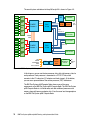
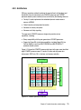
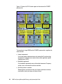
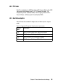
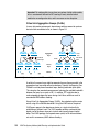
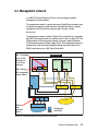
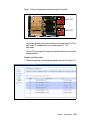
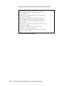
The overall system architecture for the p260 and p24L is shown in Figure 4-9.
DIMM
DIMM
SMI
DIMM
DIMM
SMI
DIMM
DIMM
SMI
DIMM
DIMM
SMI
POWER7
Processor 0
GX++
4 bytes
PCIe
to PCI
P7IOC
I/O hub
SMI
DIMM
DIMM
SMI
DIMM
DIMM
SMI
DIMM
DIMM
SMI
To
front
panel
USB
controller
Each:
PCIe 2.0 x8
I/O connector 1
4 bytes
each
DIMM
DIMM
HDDs/SSDs
SAS
I/O connector 2
POWER7
Processor 1
Each:
PCIe 2.0 x8
P7IOC
I/O hub
ETE connector
Each: PCIe 2.0 x8
Flash
NVRAM
256 MB DDR2
TPMD
Anchor card/VPD
FSP
Phy
BCM5387
Ethernet
switch
Systems
Management
connector
Gb
Ethernet
ports
Figure 4-9 IBM Flex System p260 Compute Node block diagram
In this diagram, you can see the two processor slots, with eight memory slots for
each processor. Each processor is connected to a P7IOC I/O hub, which
connects to the I/O subsystem (I/O adapters and local storage). At the bottom,
you can see a representation of the service processor (FSP) architecture.
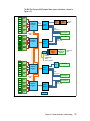
The IBM Flex System p460 Compute Node shares many of the same
components as the IBM Flex System p260 Compute Node. The IBM Flex System
p460 Compute Node is a full-wide node, and adds additional processors and
memory along with two more adapter slots. It has the same local storage options
as the IBM Flex System p260 Compute Node.
74
IBM Flex System p260 and p460 Planning and Implementation Guide