1
User's Guide
DIGI 96/8 PAD
24 Bit / 96 kHz ü
®
SyncAlign
®
ZLM
PCI Bus Audio Card
2 / 8 Channels Stereo / ADAT® Interface
24 Bit / 96 kHz Digital Audio
32-96 kHz Sample Rate
24 Bit / 96 kHz Analog Audio
Board Rev. 1.6, Hardware version 004
Contents
1
2
3
4
5
Introduction............................................................ 3
Package Contents .................................................. 3
System Requirements............................................ 3
Brief Description and Characteristics................... 3
Technical Specifications
5.1 Digital.................................................................... 4
5.2 Analog................................................................... 4
5.3 Digital Interface..................................................... 4
5.4 Transfer Modes: Resolution/Bits per Sample......... 4
6
Hardware Installation ............................................. 5
7
Software Installation
7.1 Windows 98/SE/ME............................................... 5
7.2 Windows NT.......................................................... 5
7.3 Windows 2000/XP ................................................. 6
7.4 Driver Deinstallation .............................................. 6
7.5 Linux/Unix ............................................................. 6
8
Operation and Usage
8.1 External Connectors .............................................. 7
8.2 Internal Connectors ............................................... 7
8.3 Playback (Windows MME)..................................... 8
8.4 Recording Digital (Windows MME) ........................ 9
8.5 Recording Analog.................................................10
8.6 Record while Play ................................................10
8.7 DVD Playback (AC-3/DTS) under MME................10
8.8 Low Latency under MME ......................................11
9
Configuring the DIGI 96/8 PAD
9.1 General ................................................................12
9.2 Force Adat ...........................................................14
9.3 Analog Output ......................................................14
9.4 Tab Mode.............................................................15
9.5 Boot Option ADAT................................................15
9.6 Clock Modes - Synchronization ............................16
10
Using more than one DIGI 96/8 PAD ....................17
11
Special Features of the Digital Output.................18
12
Notes on the ADAT Interface ................................19
13
Multiclient Operation
13.1 General ..............................................................19
13.2 Multichannel DirectSound...................................20
14
Operation under ASIO 2.0
14.1 General ..............................................................21
14.2 Buffer Size - Latency..........................................22
14.3 Known Problems ................................................22
15
Operation under GSIF
15.1 Windows 98/SE/ME............................................23
15.2 Windows 2000/XP ..............................................23
16
Hotline – Troubleshooting
16.1 General ..............................................................24
16.2 Installation..........................................................25
17
DIGICheck..............................................................26
18
TECH INFO ............................................................26
19
Warranty ................................................................27
20
Appendix ...............................................................27
21
Diagrams................................................................28
User's Guide DIGI96/8 PAD © RME
2
1. Introduction
Thank you for choosing the RME DIGI96/8 PAD. This card is capable of transferring
digital and analog audio data directly from DAT, Sampler or other sources to your computer.
Installation is simple, even for the inexperienced user, thanks to latest Plug & Play technology
and full interrupt-sharing. Numerous unique features and a well thought-out configuration dialog
have turned the DIGI96 series into a renowned and accepted industry standard.
Drivers for Windows (95/98, NT, 2000, XP) and MacOS (> 8.6) allow a problem-free, comfortable and powerful usage on computer systems with PCI bus technology. Drivers for Unix, Linux and Solaris are also available (see chapter 7.5). With this the DIGI96 series is supported
by a variety of Operating Systems like no other digital audio card.
Our Hi-Performance philosophy guarantees full system performance in all possible functions
not carried out by the driver (the computer´s CPU), but carried out by the DIGI96 series hardware.
2. Package Contents
Please ensure that all the following parts are included in DIGI96/8 PAD’s packaging box:
•
•
•
•
•
PCI card DIGI96/8 PAD
Quick Info guide
RME Driver CD
Adapter cable (D-type - XLR/Phono)
Internal cable (2 core)
3. System Requirements
• Windows 95/98/NT/2000/XP, Linux or MacOS
• A free PCI bus slot
Additional system requirements such as CPU, memory etc. depend on the software being used
for recording, playing and editing the audio data.
4. Brief Description and Characteristics
•
•
•
•
•
•
•
•
•
•
•
•
•
•
•
All settings can be changed in real-time, all output options even in playback mode
Separate record- and playback circuits; complete master mode
Enhanced Full Duplex: Different sample rates at input and output possible
Mixed mode: ADAT in - SPDIF out and vice versa
Automatic and intelligent master/slave clock control
Unsurpassed Bitclock-PLL (audio synchronization) in ADAT mode
Optional Word Clock Module (WCM) provides word clock input and output
Track Marker Support: Supports CD/DAT Start-IDs and read out of CD subcode
Comes with DIGICheck: the ultimate measurement, analysis and test tool
ADAT tracks routeable to analog output
Enhanced Zero Latency Monitoring: hardware bypass per track, controlled by Punch-I/O
SyncAlign guarantees sample aligned and never swapping channels
Full interrupt-sharing
Windows driver with Pentium optimization (quad times memory transfer)
32 bit memory transfer and fast 128 kB SRAM guarantee very low system load
User's Guide DIGI96/8 PAD © RME
3
5. Technical Specifications
5.1 Digital
•
•
•
•
•
•
•
•
•
Ultra-low jitter SPDIF: < 1 ns in PLL mode (44.1 kHz, optical in)
Ultra-low jitter ADAT: < 2 ns in PLL mode (44.1 kHz, optical in)
Input PLL ensures zero dropout, even at more than 40 ns jitter
Bitclock PLL for trouble-free varispeed in ADAT mode
High-sensitivity input stage (< 0.2 Vss input level)
Output voltage 0.8V (phono), 3.5V (XLR)
Supported sample rates: 32 / 44.1 / 48 / 64 / 88.2 / 96 kHz and variable (word clock)
Supports all known formats mono/stereo from 16 to 24 bit
Supports all known multi channel formats from 16 to 24 bit
5.2 Analog
•
•
•
•
•
•
•
•
Input sensitivity adjustable through jumper +4 dBu / -10 dBV
Dynamic range input: 105 dB (RMS unweighted, unmuted), 109 dBA
THD+N input: < -100 dB / < 0.001 %
Frequency response AD, -0.1 dB: 10 Hz - 20,3 kHz (sf 44.1 kHz)
Frequency response AD, -0.5 dB: 5 Hz - 44,8 kHz (sf 96 kHz)
Sample rates record: 32 / 44.1 / 48 / 64 / 88.2 / 96 kHz and variable (word clock)
Input impedance: 10 kOhm
Channel separation: > 110 dB
•
•
•
•
•
•
•
•
Analog output fixed +10 / +4 / -2 / -8 dBu @ 0 dBFS, and variable (fader)
Dynamic range output: 108 dB (RMS unweighted, unmuted), 112 dBA
THD+N output: -100 dB / 0.001%
Frequency response DA, -0.1 dB: 20 Hz - 20.8 kHz (sf 44,1 kHz)
Frequency response DA, -0.5 dB: 10 Hz - 44 kHz (sf 96 kHz)
Sample rates playback: 32 / 44.1 / 48 / 64 / 88.2 / 96 kHz and variable (word clock)
Ouput impedance: 75 Ohm
Channel separation: > 110 dB
5.3 Digital Interface
• Inputs and outputs ground-free transformer coupled
• Connectors: optical (TOSLINK), coaxial (phono), XLR, internal (CD-ROM/Sync-In / Out)
• Formats: SPDIF, AES/EBU (Consumer/Professional), ADAT optical
5.4 Transfer Modes: Resolution / Bits per Sample
•
•
•
•
•
•
16 bit 2 bytes
20 bit 3 bytes
20 bit 4 bytes
24 bit 3 bytes
24 bit 4 bytes MSB
32 bit 4 bytes
(stereo 4 bytes) (*)
MSB (stereo 6 bytes)
MSB (stereo 8 bytes) (*)
(stereo 6 bytes)
(stereo 8 bytes) (*)
(stereo 8 bytes) (*)
All the above formats are also available in Multi-Device mode (4 x stereo = 8 channels). The
Channel Interleave mode (1 x 8) provides the following resolutions:
• 16 bit 16 bytes (*)
• 24 bit 24 bytes
• 24 bit 32 bytes (*)
User's Guide DIGI96/8 PAD © RME
4
6. Hardware Installation
Important: Switch off the computer and remove the power cable from the power supply before fitting the DIGI96/8 PAD. Inserting and removing the card while the computer is in
operation will more than likely lead to irreparable damage to the mainboard!
1. Disconnect the power cord and all other cables from the computer
2. Remove the computer's housing; further information on how to do this can be obtained from
your computer´s instruction manual
3. Important: Before removing the DIGI96/8 PAD from its protective bag, discharge any
static in your body by touching the metal chassis of the PC.
4. Insert DIGI96/8 PAD firmly into a free PCI slot, press and fasten the screw.
5. Replace the computer's housing and tighten the screws.
6. Reconnect the power cable and all other cables/connections.
7. Software Installation
7.1 Windows 95/98/SE/ME
After the hardware has been installed correctly (see 6. Hardware Installation), and the computer
has been switched on, Windows will recognize the new hardware component and start its ‘Add
New Hardware Wizard’. Insert the RME Driver CD into your CD-ROM drive, and follow further
instructions which appear on your computer screen. The driver files are located in the directory
\DIGI96 W9x on the RME Driver CD.
Windows will install the DIGI driver, and will register the card in the system as a new audio
device. The computer should now be re-booted.
Unfortunately, in seldom cases, the path to the CD-ROM (i.e. its drive-letter) has to be typed
in again during the copy process.
All cards of the DIGI96 series are quickly and easily configured through the Settings dialog of
the DIGI96 driver. The Settings dialog is started in three different ways:
• by clicking on the DIGI icon in the Taskbar's system tray
• by starting the 'Digi96' link from the Desktop
• via ‘shortcut key’ as defined in the 'Digi96' link (default: Ctrl-Num2)
7.2 Windows NT
As automatic hardware recognition has not been implemented in Windows NT 4.0 the drivers
have to be installed ‘by hand’.
After the hardware has been installed correctly (see 6. Hardware Installation) and Windows NT
has been booted, insert the RME Driver CD into your CD-ROM drive. Register the new device
by starting >Control Panel /Multimedia /Devices /Audio Devices /Add<. Change to the CD's
directory to \NT in the CD-ROM. Windows NT will now install the driver. The RME Settings
dialog will open automatically.
A click on ‘OK’ finishes the installation. After a reboot the DIGI symbol will show up in the
systray of the taskbar. The DIGITray tool will be loaded automatically each time when booting
NT.
A left mouse click on the DIGI symbol starts the 'Settings' dialog. The NT driver supports any
combination of up to three RME cards. The driver is installed only once for all cards in the system.
User's Guide DIGI96/8 PAD © RME
5
7.3 Windows 2000/XP
After the hardware has been installed correctly (see 6. Hardware Installation), and the computer
has been switched on, Windows will recognize the new hardware component and start its
‘Hardware Wizard’. Insert the RME Driver CD into your CD-ROM drive, and follow further instructions which appear on your computer screen. The driver files are located in the directory
\DIGI96 W2k on the RME Driver CD.
Windows will install the DIGI96 driver, and will register the card in the system as a new audio
device. The card now ready for use.
All cards of the DIGI96 series can be easily configured using the RME DIGI Settings dialog.
The panel 'Settings' can be opened
• by clicking on the DIGI icon in the Taskbar's system tray
In case the warning messages 'Digital signature not found', 'Do not install driver', 'not certified
driver' or similar come up: Don't listen to Microsoft, listen to us and continue with the installation.
7.4 Deinstalling the Drivers
A deinstallation of the DIGI96 series driver files is not necessary – and not supported by Windows anyway. Thanks to full Plug & Play support, the driver files will not be loaded after the
hardware has been removed. If desired these files can then be deleted manually.
Unfortunately Windows Plug & Play methods do not cover the additional autorun entries of the
Settings dialog, and the registering of the ASIO driver. Those entries can be removed from the
registry through a software deinstallation request. This request can be found (like all deinstallation entries) in Control Panel, Software. Click on the entry 'DIGI96 Link and Tray Autostart', or
'RME DIGI32, DIGI96 and Hammerfall Series'.
7.5 Linux/Unix
Drivers for Linux, Unix and Solaris are available at 4Front Technology. Information:
http://www.opensound.com
Another source of (free) drivers is the ALSA project:
http://www.alsa-project.org
User's Guide DIGI96/8 PAD © RME
6
8. Operation and Usage
8.1 External Connectors
The DIGI96/8 PAD has 3 external inputs and outputs. The current input is activated
through 'Settings', available by a click on the DIGI symbol in the Taskbar's system tray. The
card accepts all commonly used digital sources as well as SPDIF and AES/EBU. Channel status and copy protection are ignored.
Use the supplied breakout cable to connect coaxial (SPDIF) or XLR (AES/EBU) devices. The
red phono socket of the breakout cable is the SPDIF output, the white one is the SPDIF input.
The ground-free design, with transformers for digital inputs and outputs, offers a problem-free
connection of all devices along with perfect hum rejection.
All outputs are driven in
parallel, therefore carrying identical signals. In
the simplest situation,
connect 3 devices at the
outputs and use the
card as a splitter (distribution 1 to 3).
Two ¼" TRS (stereo)
jacks are fitted to provide a 2-channel unbalanced analog input and output. The analog output
is directly driven from the digital output. A superior 24 bit DAC, followed by a low impedance
driver stage, allows the connection of stereo headphones. The settings dialog allows to change
the output level from 0 dB down to -78 dB. A special mute circuit reduces noise when switching
the computer on and off. The sensitivity of the analog input can be set per channel to +4 dBu or
-10 dBV by jumpers on the board. A sensitivity control by the driver or Settings dialog is not
available.
8.2 Internal Connectors
The DIGI96/8 PAD has one internal digital input and output, provided by 2-pin connectors on the board. The internal input ST3, labelled CD IN / Sync In, can be connected to an
internal CD-ROM drive having a digital audio output (advantage: the built in CD-ROM drive is
sufficient for digital recording and the need for external cabling does not arise). Or it can be
connected with the internal output of another DIGI96 series card (synchronizing multiple cards),
or an AEB4/8-I. The latter is possible because the internal input accepts both SPDIF and ADAT
format.
The internal output ST4, labelled Sync Out, provides a copy of the current external output
signal, no matter if SPDIF or ADAT. Besides connecting a AEB4/8-O for an output of up to 8
analog channels, the internal loopback proves to be a useful application. Use the supplied two
pin cable to connect Sync In and Sync Out, set the card to Clock Mode 'Master' and selectal
'Internal' as input. Now the output signal shows up directly at the card's input. This allows you to
record the playback signal, or to display the playback signals with our DIGICheck software.
The two connectors ST6 and ST7 provide a connection to the optional Word Clock Module
WCM. ST7 is also needed when connecting a AEB4/8-I. See the manuals of these products for
more information.
User's Guide DIGI96/8 PAD © RME
7
8.3 Playback (Windows MME)
DIGI96/8 PAD can play back audio data only in supported formats (sample rate, bit resolution). Otherwise an error message appears (for example at 22 kHz and 8 bit).
In the audio application being used, DIGI96/8 PAD must be selected as the output device. This
can often be found in the Options, Preferences or Settings menus under Playback Device, Audio Devices, Audio etc. Only a few programs exclusively use Windows' Preferred Playback
Device. This setting can be changed in >Control Panel /Multimedia /Audio<. We recommend
using 24-bit resolution for playback to use the DIGI96 series fullest potential.
We strongly recommend switching all system sounds off (via >Control Panel /Sounds<). Also
DIGI96/8 PAD should not be the Preferred Device for playback, as this could cause loss
of synchronization and unwanted noises. If you feel you cannot do without system sounds, you
should consider buying a cheap Blaster clone and select this as Preferred Device in >Control
Panel /Multimedia /Audio<.
The RME Driver CD includes step by step instructions for configuring many popular audio applications. Start setup.htm or setup2.htm (in the \rmeaudio.web\techinfo\ directory).
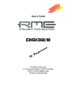
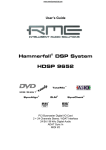
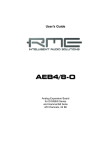
The screenshot to the
right shows a typical configuration
dialog
as
displayed by a (stereo)
wave editor. In ADAT
mode a playback is done
using the currently chosen
stereo pair. In SPDIF
mode playback always
uses channels 1+2.
Increasing the number
and/or size of audio buffers may prevent the audio signal from breaking
up, but also increases
latency i.e. output is delayed. For synchronized
playback of audio and
MIDI, be sure to activate
the checkbox ‘Get position from audio driver’. Even at higher buffer settings in a mixed Audio/MIDI environment, sync problems will not arise because the DIGI96/8 PAD always
reports the current play position correctly (even while recording - essential for chase lock synchronization).
User's Guide DIGI96/8 PAD © RME
8
8.4 Recording Digital (Windows MME)
Unlike analog soundcards, which produce empty wave files (or noise) when no input signal is
present, digital I/O cards always need a valid input signal to start recording (this includes the
correct sample frequency as well).
To take this into account, RME has included three unique features in the DIGI96 series: an
error LED for the active digital input in use, a comprehensive I/O signal status display (showing
sample frequency, lock and format) in the Settings dialog, and the protective Check Input function.
The error LED indicates whether the card gets power and a valid digital input signal. Whenever
an error occurs (wrong input, invalid data, signal transmitting device delivers nothing), the LED
will light red. As soon as a valid input signal is present the LED will turn off. The display of the
sample frequency (see chapter 9, picture Settings) in the Status display offers a similar function. If no sample frequency can be recognized ‘Out Of Range’ will be shown, in case of an error
detection ‘No Lock’.
If a 48 kHz signal is fed to the input and the application is set to 44.1 kHz, Check Input stops
the system from recording. This prevents faulty takes, which often go unnoticed until later on in
the production. Such tracks appear to have the wrong playback rate - the audio quality as such
is not affected. 'Check Input' may be switched off for vari-speed purposes.
Therefore configuring the software to perform a digital recording is child´s play. After selecting
the required input DIGI96/8 PAD displays the current sample frequency. This parameter
can then be changed in the application’s audio attributes (or similar) dialog.
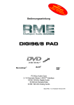
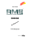
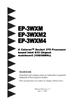
The screenshot to the right shows a typical dialog used for changing basic parameters such as
sample frequency and resolution in an audio
application.
Any bit resolution can be selected, providing it is
supported by both the audio hardware and the
software. Even if the input signal is 24 bit, the
application can still be set to record at 16-bit
resolution. The lower 8 bits (and therefore any
signals about 96dB below maximum level) are
lost entirely. On the other hand, there is nothing
to gain from recording a 16-bit signal at 24-bit
resolution - this would only waste precious space
on the hard disk.
It often makes sense to monitor the input signal or send it directly to the output. The DIGI96
series includes a useful input monitor function, which can be set in the RME DIGI Settings
(Output/Automatic). Activating Record or Pause in the application causes the input signal to be
passed directly to the digital and analog output. However, some applications block monitoring
by constantly activating playback, even if the played back track is empty. This is often required
by programs to ensure that timing and punch I/O will work correctly.
Currently two solutions exist which enable real-time monitoring even when playback is active.
Our ZLM (Zero Latency Monitoring) technology allows monitoring in Punch I/O mode - with this
the card behaves like a tape machine. This method has been implemented in all versions of
Samplitude (by SEK’D), and can be activated using the global track option 'Hardware monitoring during Punch'.
The other solution is to use our ASIO 2.0 drivers with a ASIO 2.0 compatible program. When
'ASIO Direct Monitoring' has been switched on, the input signal is routed in real-time to the
output whenever record is started.
User's Guide DIGI96/8 PAD © RME
9
8.5 Recording Analog
Use the RME Settings dialog to set the active input to 'Analog' and to activate the line inputs
(stereo ¼" TRS jack, wiring diagram see appendix). Two jumpers labelled J2/J3 allow you to
change the input sensitivity to the most common levels +4 dBu (jumper pulled) and -10 dBV
(jumper in place). A full scale level (0 dBFS) requires +19 dBu respectively +2 dBV analog
input level. In most cases the factory default -10 dBV proves to be a good choice, because it is
highly compatible to many analog devices.
8.6 Record while Play
DIGI96/8 PAD allows the playback of audio data during the recording of further audio
data, even at different sample frequencies. This feature, known as Enhanced Full Duplex or
Record while play, is a must for multitrack harddisk recording, but it has to be supported by the
recording software.
8.7 DVD-Playback (AC-3/DTS) under MME
When using popular DVD software player like WinDVD and PowerDVD, their audio data stream
can be send to any AC-3/DTS capable receiver, using the DIGI96 series' SPDIF output. For this
to work the DIGI96 output wave device has to be selected in 'Control Panel/Sounds and Multimedia/Audio'. Also check 'use preferred device only'.
You will notice that the DVD software's audio properties now allow to use 'SPDIF Out' or to
'activate SPDIF output'. When selecting these, the software will transfer the non-decoded digital multichannel data stream using the RME card.
This 'SPDIF' signal sounds like chopped noise at highest level. Therefore check 'Non-audio' in
the card's Settings dialog, to prevent most SPDIF receivers from accepting the signal, and to
prevent any attached equipment from being damaged.
Setting the card to be used as system playback device is against common sense, as professional cards are not specialized to play back system sounds, and shouldn't be disturbed by
system events. To prevent this, be sure to re-assign this setting after usage, or to disable any
system sounds (tab Sounds, scheme 'No audio').
Note: The DVD player will be synced backwards from the RME card. This means when using
AutoSync and/or word clock, the playback speed and pitch follows the incoming clock signal.
User's Guide DIGI96/8 PAD © RME
10
8.8 Low Latency under MME (Buffer Size Adjustment)
Using Windows 95 or 98 the MME buffer size was nothing to worry about. Latencies below 46
ms were not possible. Meanwhile both computers and operating system have become much
more powerful, and since Windows ME/2000/XP latencies far lower can be used. SAWStudio
and Sonar allowed to use such low settings from the start. Sequoia was updated in version
5.91, WaveLab in version 3.04.
In the Settings dialog the MME buffersize (in fact the DMA buffer size) is set with the same
buttons as the ASIO buffer size. Please note that this setting only defines the buffer size of the
hardware. The true and effective latency is configured within the MME application!
Attention: the DMA buffers must not be larger than the application's buffers. This case can
happen unnoticed when using ASIO and MME at the same time (multiclient) and setting
MODE to 2048 (46 ms), while the buffers in the MME application are still set for a lower latency. Playback will be stuttering and audio will be distorted.
Example: when you set the DIGI96 to 2048 you can't use 1024 in any program. But setting the
card's MME buffer to 256 allows to use 512 and all higher values within the MME software.
User's Guide DIGI96/8 PAD © RME
11
9. Configuring the DIGI96/8 PAD
9.1 General
The hardware of the DIGI96 series includes a number of helpful, well thought-of, practical functions and options, which allow you to configure the behaviour of the card to suit many different
requirements. Through ‘Settings’ you will gain access to:
•
•
•
•
•
Input selection
Output operation
Output Channel Status
Synchronization behaviour
Input and output status display
The display of the current input frequency and format is updated every 0.5 seconds. When
choosing an input with a signal including errors or without any input signal the statement ‘No
Lock’ appears, in vari-speed operation or with sample frequencies widely out of tune ‘Out of
Range’ is shown. If the current signal has SPDIF or AES/EBU format then 'Stereo' is displayed,
with ADAT format ‘ADAT' is shown.
The three states of the output
selected through the choicebox
‘Output’ control the monitoring
behaviour
of
the
card.
‘Automatic’ sets the normal
mode where the input signal
reaches the output only whilst
recording. In this mode, when
starting a recording, feedback
occurs very often when using
digital mixing desks. ‘Play only’
solves this problem by making
sure that the input signal is never
passed to the output.
After selecting ‘Input’, the input
signal appears at the output
whenever playback is not active.
DIGI96/8 PAD saves a
continual record standby mode
and can switch itself to monitoring without active software. As
switching between the inputs is
carried out in realtime, stepping
through the inputs gives a fast
check of the incoming signals.
Settings should not be changed during playback or record if it can be avoided, as this can cause unwanted noises. Also, please note that even in 'Stop' mode, several programs keep the
recording and playback devices open, which means that any new settings might not be applied
immediately.
Specific information about the right choice of the output's Channel Status (output format Consumer / Professional) can be found in chapter 11.
User's Guide DIGI96/8 PAD © RME
12
Input
Defines the current input. Under W9x an additional option called Autoselect can be selected.
When active, the digital inputs will be changed automatically until a valid input signal is detected.
Stereo Devices (W2k only)
SyncAlign operates fully automated and should be kept active all the time. Only in case the
stereo devices must operate completetely independent, deactivating this setting may be necessary.
Safe Mode
Check Input verifies the current input signal against the settings in the record program. When
de-activated a recording will always be allowed, even with non-valid input signals.
W9x only: 'Disable DS' deactivates the DirectSound support of the driver (see chapter 13.2).
Output
With ‘Automatic’ active, the input signal reaches the output only whilst recording. ‘Play only’
prevents the input signal from being passed to the output. After selecting ‘Input’, the input signal appears at the output whenever playback is not active.
Output Format
'Automatic' sets the output to 2-channel SPDIF or 8-channel ADAT mode, according to the
current use of the card's devices. Select 'Force Adat' to constantly have the output operating in
ADAT mode. 'A/S Conv.' forces the card's output into stereo operation.
Specific information about 'Professional', 'Emphasis' and 'Non-Audio' can be found in chapter
11.
Analog Output
Track
Defines, which of the four channel pairs is sent to the analog output.
Attenuation
Attenuation of the analog output level in steps of 6 dB.
Volume
Attenuation of the analog output level via fader. With 'Couple' activated, both faders move
simultaneously.
Clock Mode
The card can be configured to use the selected input (AutoSync), a word clock signal (Word
Clock), or its internal clock (Master) as clock source.
Status Displays
The displays at the bottom of the dialog box give precise information about the current status of
the card like format of input and output signal, sample rate at input and output, or current clock
mode.
User's Guide DIGI96/8 PAD © RME
13
9.2 Force Adat
The function 'Force Adat' is a mighty feature of the DIGI96/8 series. It forces the digital output
into ADAT mode (i.e. 8-channel operation).
When using a 'normal' 2-track program to play a stereo file, you're not only able to send the
data to any SPDIF device, but also to any other ADAT interface! Just activate 'Force Adat' and
choose the stereo pair that corresponds to the channels you want the data being transfered to
(for example DIGI96/8 PAD (3+4)).
When 'Force Adat' is activated, more than one 2-channel (stereo) program can access the
ADAT interface simultaneously (see chapter 12).
If the software being used requires a continuous ADAT mode, activate the switch ‘Force Adat'
in the RME DIGI Settings dialog.
When using ASIO and only one stereo output bus, activated 'Force ADAT' causes the output to operate in ADAT format (see chapter 13).
When the DIGI is set to pass-through operation (constant monitoring of the input signal by
selecting 'Input' mode) it turns into a real-time SPDIF to/from ADAT converter, processed by
the hardware without any additional software. Activated 'Force Adat' allows you to use the card
as a format converter from SPDIF to ADAT. The stereo signal at the input is copied to all 4
stereo pairs of the output. The option 'A/S Conv.' forces the card's output into stereo operation.
Then the card works as format converter from ADAT to SPDIF. Use the 'Track' buttons to
define which one of the 4 stereo input pairs will be routed to the SPDIF output.
9.3 Analog Output
Whenever the card's output operates in ADAT format, the 2-channel analog output will play
back one of the four stereo pairs. The desired pair can be selected in the 'Track' field of the
Settings dialog. In SPDIF (stereo) mode the Track selection has no functionality.
The analog output level can be set coarse (four 6 dB steps) or fine using the faders in the field
'Volume'. Both methods operate simultaneously and with digital precision. The shown damping
values are exactly the ones used. The used technique avoids changes in frequency response
and distortion. Only the dynamic range will decrease at higher dampings, as the noise level of
the analog output stage remains unchanged.
User's Guide DIGI96/8 PAD © RME
14
9.4 Tab 'Mode'
The Buffer Size value can be set in the RME DIGI Settings dialog, tab 'Mode'. This setting determines the latency (the delay) between the audio application and the DIGI96 series, as well
as general system stability. The higher the value, the more tracks can be recorded and played
back simultaneously, and the longer the system takes to react.
In RME DIGI Settings, tab 'Mode', 4 different buffer sizes are available: 256 (6 ms), 512 (11
ms), 1024 (23 ms), 2048 (46 ms). As the real latency depends on the used sample rate, the
values are different for different sample rates:
Choice
46 ms/16 bit
23 ms/32 bit
11 ms/16 bit
6 ms/32 bit
Buffer size
2048 s
1024 s
512 s
256 s
Resolution
16 bit
32 bit
16 bit
32 bit
44.1 kHz
46.4 ms
23.2 ms
11.6 ms
5.8 ms
48 kHz
42.7 ms
21.3 ms
10.7 ms
5.3 ms
88.2 kHz
23.2 ms
11.6 ms
5.8 ms
2.9 ms
96 kHz
21.3 ms
10.7 ms
5.3 ms
2.7 ms
The stated latency describes only one way. The complete path through the computer (record
plus playback, monitoring) gives double values.
The setting of the buffer size affects all formats.
MME: Defines lowest possible latency. The current latency and bit resolution is set in the MME
application.
ASIO: Sets current latency. Defines the effective interface resolution to 16 or 32 bit.
GSIF: Sets current latency and locks the current interface resolution to 16 or 32 bit. In Gigastudio's Hardware Settings the same (and only this) resolution will be displayed, either 24 (32) or
16 bit.
9.5 Boot-Option ADAT
The jumper JP4, labelled 'Boot ADAT', configures the card's state between power-on of the
computer and completed boot of the OS. The card is shipped with the jumper set, thus starting
in ADAT mode. This option was introduced because several external devices, especially digital
mixing desks like Yamaha's 01V or Spirit's 328 will produce noise when an SPDIF signal is
present at their ADAT input.
The other way round will normally not cause any problem, as most SPDIF and AES/EBU input
circuits recognize 'wrong' formats, and automatically mute the digital audio signal. To start the
card in SPDIF mode simply pull off jumper JP4.
User's Guide DIGI96/8 PAD © RME
15
9.6 Clock Modes - Synchronization
In the digital world, all devices are either the 'Master' (clock source) or a 'Slave' synchronized to
the master. Whenever several devices are linked within a system, there must always be a single master. The DIGI96 series includes a very user-friendly intelligent clock control, which
handles the clock switching between master and slave on its own. Click on 'AutoSync' to activate this mode.
In AutoSync mode, the card constantly scans for a valid input signal at the active input. As
soon as this matches the current playback sample rate, the card switches from the internal
quartz (display 'Clock Master') to the clock generated from the input signal (display 'Clock Slave'). This allows on-the-fly recording, even during playback, without having to synchronize the
card to the input signal first. It also allows immediate playback at any sample rate without having to reconfigure the card.
'AutoSync’ guarantees a fault-free function of the modes Record, Record while Play and while
using more than one card (see chapter 10). In certain cases however, e.g. when the inputs and
outputs of a DAT machine are connected directly to the DIGI96/8 PAD, AutoSync causes
feedback in the digital carrier, so synchronization breaks down. To remedy this, switch the
card's clock mode over to 'Master'.
Due to the outstanding clock control and PLL a synchronization of the output signal to the input
signal is not only possible at identical sample rates, but also at double/half sample rates.
AutoSync allows multiple cards to be easily synchronized by applying one input signal to all
inputs simultaneously (see chapter 10).
Thanks to the described AutoSync technology and a lightning fast PLL the DIGI96 Series is not
only capable of handling standard frequencies, but also any sample rate between 25 and 105
kHz. The digital input serves as synchronization source. Please note that at the start of a record
or playback a valid sample frequency (32 kHz, 44.1 kHz, 48 kHz, 64 kHz, 88.2 kHz, 96 kHz)
has to be fed. When started the sample frequency can be pitched to whatever is needed,
DIGI96/8 PAD will follow theses changes immediately.
When using the optional Word Clock Module (clock mode 'Word Clock') the word clock input
can serve as synchronization source. In vari-speed operation any sample frequency between
25 kHz and 105 kHz is allowed.
Only one device can be master in a digital system! When DIGI96/8 PAD operates in clock
mode 'Master', all other devices have to be 'Slave'.
More information on these subjects can be found in the HTML document 'sync96.htm', located
in the directory \rmeaudio.web\english\techinfo on the RME Driver CD, or on our web site.
User's Guide DIGI96/8 PAD © RME
16
10. Using more than one DIGI96/8 PAD
All our drivers can communicate simultaneously with all the cards registered in the system. The
driver marks them with different numbers after the device's name, like ‘DIGI96/8 PAD In (1)’.
Thanks to our AutoSync technology multiple cards can be synchronized easily by applying one
input signal to all inputs simultaneously.
In order to connect more than one DIGI96/8 PAD to a digital mixing desk they must all
get the same clock(ed input signal). This is easy to achieve: just connect at least one input of
each card to one output of the mixing desk.
Example 1: All DIGI's digital inputs are connected to other devices synced to the word clock
net.
Activate the corresponding input of each card in its Settings dialog, and activate the mode AutoSync at all cards.
Example 2: Only the outputs of the DIGIs are connected to other devices.
Connect the internal Sync-Out of the master card to the Sync-In (CD-ROM) of the second card,
activate its internal input and AutoSync mode. Next connect the third card in the same way,
from the second's card Sync-Out to the third's card Sync-In. Configure this card like the second
one. The necessary 2-wire cables are the ones supplied with the DIGI cards. Of course this
method is also operational with the external connectors, like optical or coaxial, as long as the
corresponding input is activated.
A convenient alternative is the test mode of the optional Word Clock Module WCM.
Please note when using more than one card plus the word clock output that only one card
can be master!
Example 3: All DIGIs are correctly connected to the Word Clock Module.
Activate the test mode by pushing the test switch, so the red LED lights up. Next activate the
mode 'Word Clock' in all card's settings dialogs. Now all cards should show 'Word Clock' in the
third line of 'Output Status'.
After activating the test mode all internally connected cards are immediately synchronized, in
case clock mode 'Word Clock' was activated in all settings dialogs.
More information on this subject can be found in the HTML document 'sync96.htm', located in
the directory \rmeaudio.web\english\techinfo on the RME Driver CD, or on our web site.
User's Guide DIGI96/8 PAD © RME
17
11. Special Features of the Digital Output
Apart from the audio data itself, digital audio signals in SPDIF or AES/EBU format include a
header containing Channel Status information. False Channel Status is a common cause of
malfunction. The DIGI96 series ignores the received header and creates a totally new one for
the output signal.
Note that in record or monitor modes, set emphasis bits will disappear. Recordings originally
done with emphasis should always be played back with the emphasis bit set!
This can be done by selecting the ‘Emphasis’ switch in the Settings dialogue. The changes in
sound caused by this setting can be monitored in real-time at the analog output jack. At 64,
88.2 and 96 kHz sample rate the analog output does not support De-Emphasis, so no change in
sound will be audible.
The DIGI96 series' new output header is optimized for largest compatibility with other digital
devices:
•
•
•
•
•
•
•
32 kHz, 44.1 kHz, 48 kHz, 64 kHz, 88.2 kHz, 96 kHz, depending on the current sample rate
Audio use, Non-Audio
No copyright, copy permitted
Format Consumer or Professional
Category General, generation not indicated
2-Channel, No Emphasis or 50/15 µs
Aux bits audio use
Note that most consumer-orientated equipment (with optical or phono SPDIF inputs) will
only accept signals in ‘Consumer’ format!
The status 'Professional' should always be activated when using AES/EBU format (when the
XLR connectors are used).
The audio bit in the header can be set to 'Non-Audio'. This is necessary when Dolby AC-3 encoded data is sent to external decoders (surround-sound receivers, television sets etc. with AC3 digital inputs), as these decoders would otherwise not recognize the data as AC-3.
When playing back in multi channel mode (using the optical ADAT interface) the XLR and
coaxial connectors will be turned off. This prevents sound disturbance by the ADAT signal fed
to SPDIF or AES/EBU inputs.
User's Guide DIGI96/8 PAD © RME
18
12. Notes on the ADAT Interface
DIGI96/8 PAD comes with two different driver methods in one driver. Using channel
interleave there is only one device, the software in use divides the channels into 8 mono tracks.
Because this easy to handle 'Windows native' method is not widely used the DIGI96/8
PAD also supports Multi-Device operation. The driver routes the 8 tracks in 4 stereo devices.
These 4 stereo devices can be used by nearly any software to record or playback more than 2
channels simultaneously, making DIGI96/8 PAD compatible to a wide range of already
existing software.
DIGI96/8 PAD includes an intelligent hardware controller for ease of use. Whenever
more than 2 channels are used, no matter with record, playback or both, the card switches into
ADAT mode. Whenever an ADAT signal is present at the optical input the settings dialog of the
DIGI96/8 PAD indicates ‘ADAT 44,1 kHz' or 'ADAT 48 kHz'. If now the output function is
set to ‘Input’ while AutoSync is active the card's output changes to ADAT mode to allow input
monitoring of up to 8 channels. The analog output allows you to listen to any of the four stereo
pairs. The desired pair can be selected in the 'Track' field of the Settings dialogue.
If the software being used requires a continuous ADAT mode activate the switch ‘Force Adat' in
the Settings dialog.
When using a 'normal' 2 track program to play or record a stereo file, you're not only able to
send the data to any SPDIF device but also to any other ADAT interface! Just activate 'Force
Adat' and choose the stereo pair that corresponds to the desired channels (for example
DIGI96/8 PAD (3+4)).
In SPDIF mode it doesn't matter which stereo device is being used.
13. Multiclient Operation
13.1 General
The DIGI96/8 series supports multiclient operation. That means more than one program can be
used at the same time. But this mode is only available as long as certain rules are followed. For
a flawless multiclient operation with multiple programs the below guidelines have to be followed
precisely.
Rule 1: Multiclient operation always requires the activation of Force Adat!
After an activation of Force Adat all 4 output pairs can be used freely. You can use 4 different
MME programs, or two stereo pairs under ASIO, one under GSIF and one under MME – any
combination is allowed.
Rule 2: Multiclient operation always requires identical sample rates and bit resolutions!
It is not possible to run one program at 44.1 kHz and another one at 48 kHz. Also it's not possible to run one program in 16 bit and another one in 24 (32) bit resolution. Please note that the
selected latency (Mode) also sets the bit resolution for GSIF and ASIO!
User's Guide DIGI96/8 PAD © RME
19
Rule 3: It is not possible to use the same channels with different programs simultaneously.
If for example Cubase uses channels 1/2 (default in Cubase, Master bus), this output pair can't
be used in Gigasampler/Studio (default) nor under MME.
13.2 Multi Channel Direct Sound (Win 9x only)
The Windows 95/98 driver of the DIGI96 series supports DirectSound. Due to compatibility
reasons DirectSound is de-activated by default. To activate the DirectSound support un-check
'Disable DS' in the Settings dialog.
Additionally the driver offers multi-device DirectSound. This mode is not officially supported by
Windows 95/98, but works perfectly for example with BPM-Studio. In this mode
DS/ASIO/MME/GSIF can be used simultaneously, as long as different channels are assigned to
each driver format. Only the combination ASIO/MME is not supported.
The multi-device mode for DirectSound requires 'Force ADAT' to be set in the Settings dialog!
The DIGI96 series requires identical formats when used in multi-client operation! All programs
simultaneously accessing the DIGI MUST use the same sample rate and bit resolution.
User's Guide DIGI96/8 PAD © RME
20
14. Operation under ASIO 2.0
14.1 General
As Steinberg is the inventor of ASIO we have chosen Steinberg's Cubase VST as example on
how to use and setup our cards in ASIO operation.
Our ASIO driver supports any
combination of cards from the
DIGI96 series. Important: Multiple cards MUST be synchronized among themselves! This
may be done by using the
input signal (having a common
clock source, for example a
digital mixing desk), several
synchronized ADATs or the
RME Word Clock Module.
Start the ASIO application, go
to ASIO/System and choose
the device 'ASIO DIGI96 Series'. The button 'ASIO system
control' directly starts the Settings dialog of the DIGI96
series (see chapter 9).
Switching between SPDIF (2 channel) and ADAT (8 channel) is done in a very easy and convenient way.
Playback: When using more than 2 tracks (Master bus plus at least one other) the card switches into ADAT mode. Simply activate 'Force Adat' in the settings dialog in case the ADAT
format is desired when playing back only 2 tracks.
Record: The card automatically recognizes ADAT or SPDIF signals and immediately switches
into the corresponding mode. It doesn't matter how many inputs are activated. When more than
one input is active and a SPDIF signal is present at the input this (stereo) signal will be routed
to input 1+2.
Mixed Mode: Because of the extended ASIO driver concept it is possible to record from a
SPDIF source while playing back in ADAT format and vice versa (Mixed Mode). Under certain
configurations sync problems might occur, which make it neccessary to use an external word
clock for all participating devices.
The Enhanced Zero Latency mode of the DIGI96 series enables the 'ASIO Direct Monitoring'
feature of the ASIO 2.0 standard to be used. Please note that in this mode neither routing nor
pan are supported so the input signals will only be routed to the same output channel. Other
VST mixer settings have no effect.
User's Guide DIGI96/8 PAD © RME
21
14.2 Buffer Size - Latency
The Buffer Size value in the RME DIGI Settings dialog determines the latency (in this case the
delay) between the audio application and the DIGI96 series as well as general system stability.
The higher the value, the more tracks can be recorded and played back simultaneously, and
the longer the system takes to react.
The indicated bit resolution is independent from the chosen bit resolution in Cubase. Selecting
16 bit in the driver and 24 bit in Cubase will cause Cubase to record 16 bit data and 8 bit zeroes. Selecting 24 bit in the driver and 16 bit in Cubase, the bits 17 to 24 get lost (which only
matters if they included information at all).
Please note that the latency setting describes only one way. The complete path through the
computer (record plus playback, monitoring) gives double values.
More information on how to set up the latency under ASIO can be found in chapter 9.4, Tab
'Mode'.
14.3 Known problems
In case the used computer has no sufficient CPU-power and/or sufficient PCI-bus transfer rates, then drop outs, crackling and noise will appear. We also recommend to deactivate all PlugIns to verify that these are not the reason for such effects.
Unfortunately some newer UltraATA66 and UltraATA100 hard disk controller (also Raid controller) seem to violate against the PCI specs. To achieve the highest throughput they hog the PCI
bus, even in their default setting. Thus when working with low latencies heavy drop outs (clicks)
are heard. Try to solve this problem by changing the default setting of the controller (for example by reducing the 'PCI Bus Utilization').
Another typical source of trouble is wrong synchronization. ASIO does not support asynchronous operation. This means input and output signal must not only have the same sample frequency, but must also be 'in sync' for error-free Full Duplex operation.
User's Guide DIGI96/8 PAD © RME
22
15. Operation under GSIF (Gigasampler Interface)
15.1 Windows 98/SE/ME
The GSIF interface of the DIGI96 series Windows 98/SE/ME driver allows direct operation with
Gigasampler and Gigastudio, with up to 8 channels, 96kHz and 24bit. Additionally the driver
supports multi-client operation. For example ASIO can use channels 1/2 and Gigastudio (with
GSIF) channels 3/4 simultaneously, and so on.
In case more than 2 channels shall be used under GSIF, activate 'Force ADAT' in the Settings dialog before starting the software.
Gigasampler/Studio requires a lot of the computer’s calculation power. An optimum performance is achieved with a stand-alone GSIF PC. Else we recommend not to use the DIGI96 ASIO
driver, but the ASIO Multimedia driver. It can be set to much higher latencies (i.e. 750 ms),
thus providing a problem-free simultaneous operation of ASIO and Gigastudio. Gigastudio itself
will still work at a very low latency.
The DIGI96 series requires identical formats when used in multi-client operation! All programs simultaneously accessing the hardware MUST use the same sample rate and bit
resolution. Otherwise de-tuned sound or no sound at all will be heared.
Additional simultaneous operation of GSIF and ASIO requires to use different channels. As
Cubase VST always uses tracks 1/2 these tracks must not be activated in Gigastudio/Sampler.
The tracks activated under GSIF have to be de-activated in ASIO.
Please note that the ASIO Multimedia driver will use the maximum bit resolution by default. If
the bit resolution of Gigasampler/Studio and other programs do not match, audio output will be
stopped, until the settings match and a reset is initiated ('Reset Devices' or software restart).
15.2 Windows 2000/XP
Basically as under Windows 9x. Differences: GSIF under W2k/XP uses a modified interface,
which needs interrupts (similar to ASIO). Therefore the user can now set and change the latency (under W9x latency was fixed inside Gigastudio). However, when using the Hammerfall
DSP, the latency is always the same as the one selected for ASIO operation. This can cause
performance problems on slower machines when using GSIF and ASIO at the same time.
Please note that the W2k/XP driver fully supports multiclient operation, including the combination MME/ASIO. So for example Cubase, Gigastudio and Sonar can be used simultaneously,
provided each of these programs uses its own audio channels exclusively. Please also note
that Gigastudio is running unexpectedly in the background (thus blocking its assigned audio
channels), as soon as the Gigastudio MIDI ports are used – even when Gigastudio itself hasn't
been started.
User's Guide DIGI96/8 PAD © RME
23
16. Hotline - Troubleshooting
16.1 General
The newest information can always be found on our website www.rme-audio.com, section FAQ,
Latest Additions.
Playback works but recording doesn´t:
• Check that a valid input signal is at hand. In this case the Error LED on the hardware turns
off, and the current sample frequency is shown under 'Settings'.
• If you are sure that a valid signal is being sent but the LED is still red, then check the currently selected input in the Settings dialogue.
• Check whether the DIGI96/8 PAD has been selected as recording device in the audio
application.
• Check whether the sample frequency set in the audio application (‘Recording properties’ or
similar) matches the input signal.
• Check that there is no loop cabling present. If so set 'Clock Mode' to 'Master'.
The input signal cannot be monitored in real-time
• Monitoring has not been enabled (for example 'Global disable' in Cubase).
Only the playback signal, but not the record (input) signal is present at the output
•
The DIGI96 series has no hardware mixer. Therefore while playback is running only the
playback signal is present at the output. The mixing of record and playback signal has to be
done in the software (for example deactivate Cubase's 'ASIO Direct Monitoring').
The SPDIF output does not work
• The output operates in ADAT Mode, see Output Status Display. This may be caused by
Force Adat being activated, an activation of more than the first (1/2) Master output busses in
Cubase, or when 'Max I/O' (under Hardware & Driver) wasn't set to 2 in Logic.
Low Latency ASIO operation under Windows 2000/XP on single CPU systems:
• To use ASIO at lowest latencies under Windows 2000/XP even when only having one CPU,
the system performance has to be optimized for background tasks. Go to Control Panel/System/Advanced/Performance Options. Change the default 'Applications' to 'Background tasks'. The lowest usable latency will drop from 23 ms to around 3 ms. This is no issue when using dual CPU systems.
The recording or the playback is disturbed by crackling:
•
•
•
•
•
•
Increase the quantity and size of the buffers in the software being used.
Use a different cable (coaxial or optical) to cross-check them for defects.
Check that there is no loop cabling present. If so set 'Clock Mode' to 'Master'.
In case of loop cabling with an ADAT we recommend to use the ADAT as master (Int) and
the DIGI as slave (AutoSync).
Increase the buffer size of the hard disk cache (example: from 64 kB to 256 kB).
Activate Busmaster mode for the hard disks. Windows: Device Manager, double-click on
‘Disk drives’, then on the required hard disk(s). Select ‘DMA’ in the Properties dialog.
User's Guide DIGI96/8 PAD © RME
24
Cubase seems to work, but no signal shows up at the output of the DIGI96
•
This can also happen with Logic or other programs. Most propably Gigasampler/Gigastudio
has been installed. Programs like Cubase then use the newly installed Gigastudio MIDIPorts, thus activating GSIF on the audio channels which are set inside Gigastudio (default:
1/2). As a result ASIO (also 1/2) is blocked. This effect vanishes as soon as the Gigastudio
ports are deactivated in Cubase' Setup MME.
16.2 Installation
More information on installation problems (which fortunately are very seldom, thanks to Plug
and Play), can be found in the Tech Info 'Installation problems', located in the directory
\rmeaudio.web\techinfo on the RME Driver CD.
The card is normally found in the Device Manager (>Settings/Control Panel/System<), in the
category 'Sound-, Video- and Gamecontroller'. A double click on 'DIGI96/8 PAD' starts the properties dialog. Choosing 'Resources' shows Interrupt and Memory Range.
The newest information on hardware problems can always be found on our website www.rmeaudio.com, section FAQ, Hardware Alert: about incompatible hardware.
The dialog 'New hardware component found’ does not appear:
• Is the Error LED of the DIGI96/8 PAD lit when no cable is connected to the optical
input? If not, the card is either defect or not sitting properly in the slot.
When the card and the driver have been properly installed but no playback is possible:
• Check that the DIGI96/8 PAD appears correctly in the Device Manager. If the device
'DIGI96/8 PAD' is marked with a yellow exclamation mark then either an address conflict or
an IRQ conflict is present.
• If no yellow exclamation mark is present check the 'Resources' tab.
• Check that the DIGI96/8 PAD has been set as ‘transmitting device’ in the software.
Also check the settings under >Settings /Control Panel /Multimedia /Advanced<. Here the
DIGI96/8 PAD must appear as an audio device when it´s been correctly installed, and
can be set as the Preferred Device under 'Audio'.
The computer crashes whenever the DIGI96/8 PAD is accessed:
• If your graphics board is an older Matrox Mystique or uses a ‘968’ S3 chip, there could be a
memory allocation error. Change the memory area allocated to the DIGI9652 (via
Control Panel /System /Device Manager /DIGI968 PAD /Properties /Resources /Change
Setting) to below the area used by the graphics board (e.g. D0000000 - D0FFFFFF). Detailed information on this subject can be found in \rmeaudio.web\techinfo\install.htm on the
RME Driver CD.
User's Guide DIGI96/8 PAD © RME
25
17. DIGICheck: Analysis, Test and Measurements using the DIGI96 series
The DIGI96 series from RME is accompanied by a world wide unique software tool: DIGICheck,
the incredible utility for test, measure and analysis of the digital audio data stream.
DIGICheck is based on functions of our well-known DAM-1, the Digital Audio Monitor. This
device uses a built-in DSP for its calculations. Therefore DIGICheck is not able to realize all the
functions of the DAM-1. Additionally, the DAM-1 works perfectly in the background while DIGICheck will cause a certain CPU load.
DIGICheck also includes test routines from our research lab and our production site. Thus you
are able for the first time to run a detailed function and performance test with your own audio
card in your own computer, like it isn't possible with any other test tool.
Although the DIGICheck software is fairly self-explanatory, it still includes a comprehensive
online help. A detailed description of all functions and the technical background is also available in HTML format (digich.htm, in the \techinfo directory on the RME Drivers CD or from our
website). The following is a short summary of the available functions:
• Level Meter. High precision 24-bit resolution, 2/8 channels. Application examples: Peak
level measurement, RMS level measurement, Over detection, phase correlation measurement, dynamic range and signal-to-noise ratios, RMS to peak difference (loudness), long
term peak measurement, input check
• Channel Status Display. Shows the channel status information contained in the digital
audio data stream. Sample rate measurement
• Bit Statistics. Shows the true resolution of audio signals as well as errors and DC offset
• Performance Test. Measurement of the PCI-bus data transfer
• Memory Test. Tests the on board SRAM and the entire data path in the PC
To install DIGICheck, go to the \DIGICheck directory on the RME Drivers CD and run setup.exe. Follow the instructions prompted on the screen.
18. TECH INFO
RME provides more information on the TECH INFO pages in the web (http://www.rmeaudio.com/techinfo/index.htm), and in the directory \rmeaudio.web\techinfo on the RME
Driver CD. Here are some examples of available Tech Infos:
Synchronization II (DIGI96 series)
Digital audio synchronization: technical background, problems
Installation Problems
..and their solutions
List of Driver Updates
Lists all driver updates and the changes in them
Configuration of Samplitude, Cubase, Logic, Cakewalk 7.0, Sonar and SAWPlus32 using the
DIGI96 series. Step by step instructions
DIGICheck: Analysis, tests and measurements with the DIGI96 series
A description of DIGICheck, including technical basics.
TMS (Track Marker Support)
Description of the TMS technology to transfer CD- and DAT information.
User's Guide DIGI96/8 PAD © RME
26
19. Warranty
Each individual DIGI96/8 PAD undergoes comprehensive quality control and a complete
test in a PC environment at RME before shipping. This may cause very slight signs of wear on
the contacts (if the card looks like it was used one time before - it was). The usage of high grade components allows us to offer a full two year warranty. We accept a copy of the sales receipt as valid warranty legitimation.
RME’s replacement service within this period is handled by the retailer. If you suspect that your
card is faulty, please contact your local retailer. The warranty does not cover damage caused
by improper installation or maltreatment - replacement or repair in such cases can only be carried out at the owner’s expense.
RME does not accept claims for damages of any kind, especially consequential damage. Liability is limited to the value of the DIGI96/8 PAD. The general terms of business drawn up
by Synthax OHG apply at all times.
20. Appendix
RME news, driver updates and further product information are available on our website:
http://www.rme-audio.com
If you prefer to read the information off-line, you can load a complete copy of the RME website
from the RME Driver CD (in the \rmeaudio.web directory) into your browser.
Distributor in Germany:
Synthax Audio AG, Am Pfanderling 62, D-85778 Haimhausen, Tel.: (49) 08133 / 91810
Manufacturer:
IMM Elektronik, Leipziger Str. 27, D-09648 Mittweida
Trademarks
All trademarks and registered trademarks belong to their respective owners. RME, DIGI96,
SyncAlign, DIGICheck and ZLM are registered trademarks of RME Intelligent Audio Solutions.
SyncCheck is a trademark of RME Intelligent Audio Solutions. Alesis and ADAT are registered
trademarks of Alesis Corp. ADAT optical is a trademark of Alesis Corp. Microsoft, Windows,
Windows 98/NT/2000/XP are trademarks of Microsoft Corp. Apple and MacOS are registered
trademarks of Apple Computer Inc. Cubase and VST are registered trademarks of Steinberg
Soft- und Hardware GmbH. ASIO is a trademark of Steinberg Soft- und Hardware GmbH. emagic and Logic Audio are registered trademarks of emagic Soft- und Hardware GmbH. Pentium is a registered trademark of Intel Corp.
Copyright Matthias Carstens, 5/2002. Version 1.9
Current driver version: W98: 4.96, NT 3.86, W2k/XP: 2.0
This manual applies to board revision 1.6 or lower, hardware version 004.
Although the contents of this User’s Guide have been thoroughly checked for errors, RME can not guarantee that it is correct
throughout. RME does not accept responsibility for any misleading or incorrect information within this guide. Lending or
copying any part of the guide or the RME drivers CD, or any commercial exploitation of these media without express written
permission from RME Intelligent Audio Solutions is prohibited. RME reserves the right to change specifications at any time
without notice.
User's Guide DIGI96/8 PAD © RME
27
Analog input and output: Pin assignment of the TRS jacks
Analog input and output are accessible
through stereo ¼" TRS jacks. This allows a direct connection of headphones at the output. In case the output
should operate as line out an adapter
TRS plug to RCA phono plugs, or TRS
plug to TS plugs is required.
The pin assignment follows international standards. The left channel is connected to the tip, the right channel to
the ring of the TRS jack/plug.
Pin assignment of the jumpers next to the D-type connector
The optional jumpers (not fitted, not
supplied) next to the D-type connector
allow an internal cabling, for example when
the XLR input and output jacks shall be
build into the PC housing, so that the
supplied cable adapter is no longer needed. When using a 10 wire computer flat
cable with the appropriate connector the
connection between XLR jacks and card
will be removable.
The pins are numbered as shown in the
diagram. For a better overview the table
lists the pin assignment sorted by numbers
and names.
Pin number
1
2
3
4
5
6
7
8
9
10
Name
SPDIF Out GND
SPDIF In SPDIF Out +
AES Out +
SPDIF In +
AES In +
AES Out NC
AES In -
Name
AES In +
AES In SPDIF In SPDIF In +
AES Out+
AES Out SPDIF Out +
SPDIF Out NC
GND
Pin number
7
10
3
6
5
8
4
1
9
2
Pin assignment of the XLR/RCA Cable's D-type connector
Pin
1
2
3
Name
GND
SPDIF Out +
SPDIF In +
Pin
4
5
6
Name
AES Out +
AES In +
SPDIF Out -
Pin
7
8
9
Name
SPDIF In AES Out AES In -
User's Guide DIGI96/8 PAD © RME
28
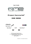
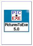
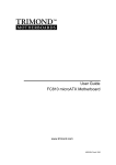
Block diagram
User's Guide DIGI96/8 PAD © RME
29
CE
This device has been tested and found to comply with the limits of the European Council Directive on the approximation of the laws of the member states relating to electromagnetic compatibility (EMVG) according to EN 55022 class B and EN50082-1.
FCC Compliance Statement
Certified to comply with the limits for a Class B computing device according to subpart J or part
15 of FCC rules. See instructions if interference to radio reception is suspected.
FCC Warning
This equipment has been tested and found to comply with the limits for a Class B digital device, pursuant to part 15 of the FCC rules. These limits are designed to provide reasonable protection against harmful interference in a residential installation.
This device complies with part 15 of FCC rules. Operation is subject to the following two conditions:
1. This device may not cause harmful interference
2. This device must accept any interference received, including interference that may cause
undesired operation.
However, there is no guarantee that interference will not occur in a particular installation. If this
equipment does cause harmful interference to radio or television reception, which can be determined by turning the equipment off and on, the user is encouraged to try to correct the interference by one or more of the following measures:
• Reorient or relocate the receiving antenna
• Increase the seperation between the equipment and receiver
• Connect the equipment into an outlet on a circuit different from that to which the receiver is
connected
• Consult the dealer or an experienced radio/TV technician for help.
In order for an installation of this product to maintain compliance with the limits for a Class B
device, shielded cables must be used for the connection of any devices external to this product.
User's Guide DIGI96/8 PAD © RME
30