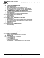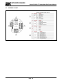
1
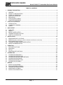
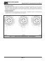
MODEL 5100-02-IT IT Series COMBUSTIBLE GAS SENSOR MODULE Version 3.00A APPLICABILITY & EFFECTIVITY Effective for all Model 5100-02-IT Modules manufactured after December 1, 2011. Instruction Manual Part Number T12019 Rev. E Model 5100-02-IT Combustible Gas Sensor Module FM APPROVAL ONLY THE FOLLOWING ITEMS, FUNCTIONS AND OPTIONS ARE FM* APPROVED Model 5100-02-IT Combustible Gas Sensor Module Sensor Module Model 5100-02-IT Combustible Gas Sensor Module Calibration Equipment Model 1200-26 Calibration Gas Delivery System Model 1290-02 Combustible Gas Cylinder Model 5358-01 Calibration Head, Standard Model 5360-00 Calibration Gas Delivery Fitting Model 1260-02 Combustible 50% LEL Gas Cylinder Model 1260-42 Cylinder H2 50% LEL Type A Model 1250-01 Gas Sensor Calibrator Kit, Type A Model 1256-01 Regulator Type A Calibrator Model 5394-51 Remote Sensor Option – 5100-02-IT Notes: 1) FM Approval applies only to conventional (one cable run per sensor module) or multiplexed (multiple sensor modules per cable) installations. Apparatus must be installed in accordance with National Electrical Code. 2) FM Comments *FM Approvals, a subsidiary of FM Global Project# 3021050 Model 5100-02-IT Combustible Gas Sensor Module TABLE OF CONTENTS 1. 1.1 1.2 1.3 1.4 1.5 1.6 1.7 2. 2.1 2.2 2.3 3. 3.1 3.2 3.3 3.4 3.5 4. 4.1 4.2 4.3 4.4 4.5 5. 5.1 5.2 5.3 5.4 6. 6.1 6.2 6.3 6.4 6.5 6.6 7. 7.1 7.2 7.3 7.4 7.5 PRODUCT DESCRIPTION ................................................................................................................................. 3 GENERAL ........................................................................................................................................................ 3 PRODUCT CONFIGURATION ........................................................................................................................ 3 THEORY OF OPERATION .............................................................................................................................. 3 MODES OF OPERATION ................................................................................................................................ 3 MECHANICAL ................................................................................................................................................. 4 INTERCONNECT WIRING .............................................................................................................................. 5 POWER REQUIREMENTS ............................................................................................................................. 5 CAUTIONS & WARNINGS ................................................................................................................................. 7 INTRODUCTION ............................................................................................................................................. 7 IT MODULES - GENERAL .............................................................................................................................. 7 WIRING............................................................................................................................................................ 7 QUICK START .................................................................................................................................................... 9 OVERVIEW...................................................................................................................................................... 9 WIRING............................................................................................................................................................ 9 MODULE INSTALLATION ............................................................................................................................... 9 TRANSMITTER INSTALLATION .................................................................................................................... 9 START-UP & OPERATION ............................................................................................................................. 9 INSTALLATION ................................................................................................................................................ 10 SENSOR MODULE LOCATIONS ................................................................................................................. 10 WIRING (FIGURE 4-2 REFERS TO ANALOG, MODBUS AND SENTRY OPERATION) ................................................. 10 ENCLOSURE INSTALLATION ...................................................................................................................... 11 TRANSMITTER AND SENSOR INSTALLATION .......................................................................................... 12 MODULE ADDRESS SWITCH ...................................................................................................................... 13 OPERATION ..................................................................................................................................................... 18 DATA ENTRY KEY PAD ................................................................................................................................ 18 MAIN MENU................................................................................................................................................... 19 SET-UP .......................................................................................................................................................... 20 MAINTENANCE FUNCTIONS ....................................................................................................................... 23 CALIBRATION .................................................................................................................................................. 24 CALIBRATION FREQUENCY ....................................................................................................................... 24 CALIBRATION PREPARATION .................................................................................................................... 24 CALIBRATION GAS DELIVERY METHODS ................................................................................................. 24 CALIBRATION PROCEDURE ....................................................................................................................... 24 SENSOR EXPOSURE TO GAS .................................................................................................................... 24 CALIBRATION SUB-MENU ........................................................................................................................... 25 SERVICE ........................................................................................................................................................... 26 MODULE SUB ASSEMBLY ........................................................................................................................... 26 ENCLOSURE REPLACEMENT .................................................................................................................... 26 TRANSMITTER REPLACEMENT ................................................................................................................. 27 SENSOR REPLACEMENT ............................................................................................................................ 27 INSTALLATION INSPECTION ...................................................................................................................... 27 Page: 1 Model 5100-02-IT Combustible Gas Sensor Module 8. 8.1 8.2 8.3 8.4 8.5 8.6 8.7 8.8 8.9 APPENDICES ................................................................................................................................................... 29 APPENDIX A: SPECIFICATIONS.................................................................................................................. 29 APPENDIX B: MODEL NUMBERS, PARTS LIST & PARAMETERS............................................................. 30 APPENDIX C: LIMITED WARRANTY............................................................................................................ 31 APPENDIX D: REMOTE SENSOR OPTION ................................................................................................. 32 APPENDIX E: HART ...................................................................................................................................... 34 APPENDIX F: MODBUS MEMORY MAP ...................................................................................................... 42 APPENDIX G: COMBUSTIBLE GAS SCALING FACTORS .......................................................................... 43 APPENDIX H: FM APPROVAL .....................................................................................................................44 APPENDIX I: SIL-2 APPROVAL CERTIFICATE............................................................................................ 46 LIST OF FIGURES FIGURE FIGURE FIGURE FIGURE FIGURE FIGURE FIGURE FIGURE FIGURE FIGURE FIGURE FIGURE FIGURE FIGURE FIGURE FIGURE 1 - 1: 1 - 2: 1 - 3: 4 - 1: 4 - 2: 4 - 3: 4 - 4: 4 - 6: 4 - 5: 4 - 7: 5 - 1: 6 - 1: 7 - 1: 8 - 1: 8 - 2: 8 - 3: MODEL 5100-02-IT COMBUSTIBLE SENSOR – MOUNTING OPTIONS .................................... 5 MODEL 5100-02-IT-S1 (AND S2) COMBUSTIBLE SENSOR – 316SS DIMENSIONS ................ 6 MODEL 5100-02-IT-A1 (AND A2) COMBUSTIBLE SENSOR –ALUMINUM DIMENSIONS ........ 6 TYPICAL MOUNTING OPTIONS ................................................................................................. 10 TRANSMITTER FACE PLATE ..................................................................................................... 14 4-20 MA CIRCUITS TYPES 5100-02-IT ...................................................................................... 14 4-20 MA CIRCUITS TYPES 5100-02-IT – CONNECTIONS........................................................ 15 REMOTE ALARM RESET ............................................................................................................ 16 DIGITAL INTERFACE CONNECTIONS ...................................................................................... 16 TERMINATION DRAWING .......................................................................................................... 17 FACE PLATE WITH DATA ENTRY KEY PAD ............................................................................. 18 MODEL 5358-01 CALIBRATION ADAPTER ............................................................................... 24 MODULE COMPONENTS ........................................................................................................... 26 REMOTE SENSOR OPTION ....................................................................................................... 32 HART ............................................................................................................................................ 34 4-20 MA CIRCUITS TYPES 5100-02-IT – CONNECTIONS - HART .......................................... 35 LIST OF TABLES TABLE TABLE TABLE TABLE TABLE TABLE TABLE TABLE TABLE 4 - 1: 4 - 2: 4 - 3: 5 - 1: 5 - 2: 5 - 3: 5 - 4: 6 - 1: 8 - 1: MINIMUM WIRE GAUGES ............................................................................................................. 12 SENSOR MODULE EXTERNAL INTERFACES ............................................................................ 13 SENSOR MODULE ADDRESS SWITCH POSITIONS .................................................................. 13 MASTER MENU ............................................................................................................................. 19 OPERATION DISPLAY VALUES ................................................................................................... 19 SET-UP CONFIGURATION ........................................................................................................... 21 MAINTENANCE MENU .................................................................................................................. 23 CALIBRATION ................................................................................................................................ 25 MODBUS MEMORY MAP .............................................................................................................. 42 Page: 2 Model 5100-02-IT Combustible Gas Sensor Module 1. PRODUCT DESCRIPTION 1.1 GENERAL The Model 5100-02-IT Catalytic Bead Combustible Gas Sensor Module is a member of the Sentry Information Technology ”IT” family of gas sensor transmitter modules. IT modules offer a broad array of features including: Integral Alphanumeric display 180 day calibration frequency SIL-2 Certified FM Approved for performance and hazardous locations 4-20 mA output Modbus® RTU interface SMC Sentry interface 316 Stainless steel enclosure option Remote alarm reset Optional Alarm Relays Remote sensor option IT modules are designed, and approved for installation and operation in hazardous locations. 1.2 PRODUCT CONFIGURATION Various module configuration options are available. Where applicable, these options are factory configured prior to shipment. 1.3 THEORY OF OPERATION Catalytic bead gas sensors detect gas by comparing the resistance of two heated elements. One element is catalytic to enhance the burning of combustible gases, the other element is passive. Electronic circuits are used to compare the change in the catalytic bead resistance relative to the passive bead. The relative change is calibrated to determine the concentration of the gas of interest. 1.4 MODES OF OPERATION 1.4.1 SENTRY INTERFACE All IT gas sensor modules can be installed on Sierra Monitor Sentry Model 5000 controllers. Catalytic bead modules communicate as a combustible gas sensor module (Type 2 communication) and are automatically detected by the Sentry controller. When it is installed in a Sentry system the IT module must have a unique address which can be established by setting an address between 1 and 8 on the rotary switch accessible from the cover plate as illustrated in Figure 4-1. Figure 4-4 in this manual provides the wiring terminations for connections to the Sentry controller. When the module is operated in conjunction with a Sentry controller, the alarm relay setup (See section 4.3) should be set to “Sentry”, allowing the Sentry controller to manage alarm relay action rather than the 5100-02-IT Gas Sensor Module. An available option, applicable only to Sentry installations, is a connector card which allows daisy chain installation using the Sentry multiplex capability. Use of the connector card reduces costs by avoiding the requirement for wiring junction boxes. The connector card has two sets of connections, allowing for a continuous run to the next module ® Registered trademark of Schneider Electric. Page: 3 Model 5100-02-IT Combustible Gas Sensor Module 1.4.2 MODBUS OPERATION An RS-485 Modbus RTU serial interface allows direct connection to standard PLCs and DCSs. The Module Address Switch (section 4.5) allows the user to select up to 15 different Modbus addresses. Also, up to 254 different Modbus Addresses are available via menu selection. Figure 4-5 in this manual provides the wiring terminations for Modbus connections. 1.4.3 ANALOG OPERATION The analog 4-20 mA interface allows direct connection to standard controller and distributed system. The module is an active current source. The standard configuration is set up for a 3-wire non-isolated connection. An optional 4-wire isolated connection is also available and can be enabled by changing JP1 and JP2. 1.4.4 REMOTE SENSOR (APPENDIX E) The Remote Sensor option enables the remote mounting of the sensor up to 50’ from the transmitter. 1.4.5 HART CONNECTION (APPENDIX F) A HART interface option is available. Refer to Appendix F for information. 1.4.6 OPTIONAL INTEGRAL RELAYS The optional relays are integral to the gas sensor module and are rated as SPDT, 250VAC, 5 Amps for the High Alarm and Low Alarm relays and SPDT, 250VAC, 0.25 Amp for the Trouble relay. * HART option, alarm relays are all SPDT, 250VAC, 2 Amp If the gas sensor module is provided with the optional relays, it will include Terminal P4 on the interface board (Figure 4-3). Relay output connections are on P4. 1.4.7 REMOTE ALARM RESET An input is available for connection of remote alarm reset/acknowledge. Figure 4-6 provides the wiring termination for connecting the remote alarm reset. This only resets local alarms, not Sentry alarms. 1.5 MECHANICAL The sensor module of comprised of the following three primary components: ENCLOSURE Standard on the 5100-02-IT is an explosion-proof, rain-tight cast aluminum electrical housing (Figure 1-2) with three ¾” FNPT conduit hubs. The 5100-02-IT-SS has a 316 Stainless Steel enclosure (Figure 1-3). Both enclosure covers have a viewing window. The design of the enclosure allows 3-way mounting choices as shown in figure 1-1. TRANSMITTER ELECTRONICS Electronic Assembly consisting of one printed circuit board assembly mounted under a cover plate, plugged into one field termination board. Connectors for wiring for power, signal interface and alarm relays are located on the bottom of the termination board. SENSOR ASSEMBLY The sensor assembly includes an explosion proof housing containing the gas sensor and a wiring harness for connection to the transmitter. The sensor assembly threads into one hub of the enclosure. The exposed end of the sensor assembly is threaded to allow connection of a rain-shield or calibration gas. Page: 4 Model 5100-02-IT Combustible Gas Sensor Module 1.6 INTERCONNECT WIRING Not supplied with the sensor module, but necessary to the installation and operation is the multi conductor wiring which connects the module to its power source and controller. Before this wiring is installed it is important to read and understand the control system installation instructions to determine wiring alternatives requirements and alternatives. 1.7 POWER REQUIREMENTS IT modules operate on DC power between 10 VDC and 30 VDC. Regulated DC power must be supplied from a separate source, or from an approved Sentry or IT controller. Figure 1 - 1: Model 5100-02-IT Combustible Sensor – Mounting Options Page: 5 Model 5100-02-IT Combustible Gas Sensor Module Figure 1 - 2: Model 5100-02-IT-S1 (and S2) Combustible Sensor – 316SS Enclosures, Dimensions Figure 1 - 3: Model 5100-02-IT-A1 (and A2) Combustible Sensor – Cast Aluminum Enclosures, Dimensions Page: 6 Model 5100-02-IT Combustible Gas Sensor Module 2. CAUTIONS & WARNINGS 2.1 INTRODUCTION Although IT Transmitter Modules are designed and constructed for installation and operation in industrial applications including "hostile" environments, caution should be taken to insure that the installation is made in compliance with this instruction manual and that certain procedures and conditions are avoided. This chapter discusses the necessary cautions. Read the entire chapter prior to installation of the equipment. 2.2 IT MODULES - GENERAL Avoid installing sensor modules where they will be unnecessarily exposed to wind, dust, water (esp. direct hose down), shock, or vibration. Observe temperature range limitations. Sensors may be adversely affected by prolonged exposure to certain materials. Loss of sensitivity, or corrosion, may be gradual if such materials are present in low concentrations. These materials include: silicones, sulfides, Halides (compounds containing chlorine, fluorine, bromine, iodine), acid vapors, caustic liquids or mists. Care has been taken by the manufacturer to ship your modules in protective packaging to avoid contamination prior to installation. It is recommended that the modules remain protected during installation and that the covering be removed immediately prior to system start-up. During normal use the sensor is protected from dirt and oil contamination by a sintered metal cover. If this cover becomes clogged, the response of the sensor will be reduced. Protect the sensor from contamination by careful placement, or by use of rain and dust shields. Sensor modules must not be painted. Paint may contain compounds which will contaminate the sensor. Paint will cause clogging of the sintered metal cover and will cause difficulties during attachment of the calibration head or other maintenance activity. It is recommended that the module be tagged "DO NOT PAINT". 2.3 WIRING The manufacturer recommends that extra caution be taken where the installation is near any sources of electromagnetic or radio frequency interference. Precautions include: Avoid running sensor module cable close to high power cables, radio transmission lines, or cables subject to pulses of high current. Avoid running cables near large electric motors or generators. When shielding is used, it is recommended that shields be grounded at the controller and nowhere else. All splices must be via either a termination hardware system or soldered. Improperly spliced cable can result in corrosion, resistance changes and system errors. The use of wire nuts and crimp-on connectors is unacceptable. NOTE Installation and wiring must be in accordance with the National Electrical Code. AC Voltage conductors are not to be run in the same conduit as DC voltage conductors. 2.3.1 CATALYTIC BEAD SENSOR MODULES Model 5100-02-IT Gas Sensor Modules are FM performance approved for detection of Combustible gas (methane and hydrogen). The sensor is cross sensitive to the combustible gases indicated in Table 2-1. Risk management planning should take into consideration the potential for the presence of other gases in the monitored area. Page: 7 Model 5100-02-IT Combustible Gas Sensor Module Note that the 5100-02-IT has a gas factor scaling feature in which a calibration standard of Methane or Propane may be used in conjunction with scaling factors to cause alarm function in %LEL scale of another gas. See Appendix G. Acetaldehyde 2,3-Dimethylpentane Methyl Chloride Acetic Acid 2,3-Dimethylpropane Methylcyclohexane Acetic Anhydride Dimethylsulphide Methylenedichloride Acetone 1,4-Dioxane Methylethylether Acetylene Epichlorohydrin Methylethylketone Alkyl Alcohol Ethane Methyl Formate Ammonia Ethyl Acetate Methylmercaptan n-Amyl Alcohol Ethyl Alcohol Methylpropionate Aniline Ethylamine Methyl n-propylketone Benzene Ethyl Benzene Napthalene Biphenyl Ethyl Bromide Nitromethane 1,3-Butadiene Ethyl Chloride n-Nonane n-Butane Ethylcyclopentane n-Octane iso-Butane Ethylene n-Pentane Butene-1 Ethylenedichloride i-Pentane cis-Butene-2 Ethyleneoxide Propane trans-Butene-2 Diethyl Ether n-Propyl Alcohol n-Butyl Alcohol Dimethoxyethane n-Propylamine iso-Butyl Alcohol Dimethyl Ether n-Propylchloride tert-Butyl-Alcohol Dimethylformamide Propylene n-Butyl Benzene Ethyl Formate Propyleneoxide iso-Butyl Benzene Ethylmercaptan iso-Propylether n-Butyric Acid n-Heptane Propyne Carbon Disulfide n-Hexane Toluene Carbon Monoxide Hydrazine Triethylamine Carbon Oxysulphide Hydrogencyanide Trimethylamine Chlorobenzene Hydrogen Vinylethylether Cyanogen Hydrogen Sulfide o-Xylene Cyclohexane Methane m-Xylene Cyclopropane Methyl Actetate p-Xylene n-Decane Methyl Alcohol JP-4 (Jet Fuel) Diethylamine Methylamine Dimethylamine Methyl Bromide Table 2 - 1: Combustible gases detected by Model 5100-02-IT Combustible Gas Sensor Module Page: 8 Model 5100-02-IT Combustible Gas Sensor Module 3. QUICK START 3.1 OVERVIEW The gas sensor module has been supplied factory calibrated and ready for immediate installation and operation. An installer familiar with installation and operation of gas detection products can use this section to begin immediate use of the module. 3.2 WIRING See section 4.2 to determine if 3-wire or 4-wire operation is necessary. Provide twisted shielded wiring from the power supply/control device to the sensor module location. Use stranded wire that is 18 AWG or larger. 3.3 MODULE INSTALLATION The sensor module can be mounted in a variety of configurations supported by the conduit. See figure 1-1 to determine which configuration is best for your specific application. The default configuration enables the modules to be put in line with other modules with the sensor element below the transmitter. To change the configuration simply remove the transmitter and rotate to the appropriate configuration and remount the standoffs and transmitter. The module is designed to be installed on a ¾” conduit. Two important warnings: The installation must meet any hazardous environment codes for electrical equipment. The sensor module enclosure mounting must be spaced far enough from any vertical surface to allow removal and replacement of the sensor assembly which is threaded into one ¾” conduit entry. Sensor housing must be oriented vertically pointing downward. If module is installed outdoors it is recommended that it be sheltered from direct sunlight. 3.4 TRANSMITTER INSTALLATION To install the transmitter printed circuit assembly into the housing, carefully turn the faceplate so that the printing is in the correct horizontal position for the mounting configuration and slide the assembly over the two stand-offs in the enclosure. Hand tighten the two captive panel thumb screws into the stand-offs. Replace the enclosure cover prior to providing power to the transmitter If the transmitter is installed in a classified hazardous area, replace the threaded cover prior to providing power. 3.5 START-UP & OPERATION To begin operation of the sensor module activate the instrument loop with 10-30 VDC. Each time the sensor module is powered up it will perform a warm-up for approximately 5-10 minutes. During this time the display will read “Starting”. The loop output will be held at 4 mA. NOTE: If the sensor is uncalibrated, the startup display will state “START” instead of “STARTING” After the warm-up period has expired, the display will indicate the gas concentration. Also, the instrument loop will be released to output current in the range of 4 to 20 mA. The actual current is linear with the gas concentration. Page: 9 Model 5100-02-IT Combustible Gas Sensor Module 4. INSTALLATION NOTE All IT modules are factory pre-configured and calibrated. All modules are tagged to indicate the configuration including the sensor module number Identify all components during unpacking and install using the factory configuration. 4.1 SENSOR MODULE LOCATIONS Select locations for each sensor modules based on the following: Modules should be placed close to the potential source of gas. Modules should be placed in areas accessible for calibration. Sensors should be pointed down and the conduit should include an inverse trap to reduce moisture (condensation) from accumulating in the electronics enclosure. Remote calibration fitting (5360-00) should be used to facilitate calibration gas delivery. Run polyurethane tubing (1/4” O.D. x 1/8” I.D.) from fitting to an accessible location. Figure 4 - 1: Typical Mounting Options NOTE Module must always be installed vertically with sensor pointing down. 4.2 WIRING (Figure 4-2 refers to Analog, Modbus and Sentry operation) 4.2.1 ANALOG 4-20 MA OPERATION For a 3-Wire non-isolated connection, set jumpers, located on the bottom of the transmitter board, to the lower position as illustrated in Figure 4.4. Verify that both jumpers are in the position marked by 3-wire. When using a 3-wire connection, a minimum of an 18 AWG, 3 conductor shielded cable must be used. A Page: 10 Model 5100-02-IT Combustible Gas Sensor Module cable shield must never be used as a conductor. Larger gauge wire is recommended with distances over 1000’. Connect wires as shown in figure 4-4. For a 4-Wire isolated connection, set jumpers, located on the bottom of the transmitter board, to the upper position as illustrated in Figure 4.4. Verify that both jumpers are in the position marked by 4-wire. When using a 4-wire connection, a minimum of 2 each of an 18 AWG, 2 conductor twisted/shielded pair cable must be used. A cable shield must never be used as a conductor. Larger gauge wire is recommended with distances over 1000’. Connect wires as shown in figure 4-4. 4.2.2 MODBUS OPERATION USING RS-485 CONNECTION Use a minimum of 18 AWG, 2 conductor for DC power connection. No shield required. In addition use a minimum of 24 AWG, low capacitance, shielded data cable for RS485 half duplex communication. The installation may be planned in a manner which provides up to 32 sensor modules on a single home run. TERMINATION RESISTOR JUMPERS: Termination resistors are used in RS-485 wire runs to provide impedance matching. The IT series modules use a 120 Ohm resistor for this function. The cable being used for this RS-485 connection must have a minimum of 100 Ohm impedance with a maximum of 120 Ohms. Installations where the cable length is under 100’, termination resistors may not be required. In installations where the cable length is greater than 100’, it is recommended to place the termination jumpers on the first device and last device on the RS-485 wire run. Termination jumpers must be removed from all other modules connected between the first and last device. The first device in the RS-485 multiplexed bus is usually a gas controller or PLC. Factory term resistor setting is “not enabled.” BIAS JUMPERS: (BIAS A, BIAS B) Bias resistors are used to force RS-485 receiver outputs to a known (fail-safe) state, when the bus is idle. Bias jumpers are always installed in pairs as the bias must be placed on both the TX A and TX B lines. Sierra Monitor’s IT series of combustible gas sensors automatically apply the bias jumpers, and are factory installed so that the bias is always enabled. 4.2.3 SENTRY OPERATION USING SENTRY PSG CONNECTION Use a minimum of 18 AWG, 3-conductor cable up to 2000’. The cable may or may not be shielded. We recommend shielded cable in circumstances that there could be RF or EM interference present. Shield to be terminated and grounded only at the Sentry controller. Shield must be cut and dressed at the module end so that no part of it comes in contact with the conduit or ground. NOTE: Be sure to follow all local electric code and safety requirements when installing the 5100-02-IT Gas Sensor Module 4.2.4 GENERAL Install conduit as required by local code or construction specifications. Provide for splice boxes where multiple modules will be wired to a single run. Pull conductors of the correct gauge wire from the controller to each splice box and from the respective splice box to each planned module location. See for proper wire termination in the splice box. Twisted wire secured with wire nuts is not an acceptable splice. NOTES RFI Noise Suppressor must be added to power/ground as per Appendix D. The drain wire of shielded cable must NOT be used as one of the conductors. Installation and wiring must be in accordance with the National Electrical Code. Temperature o rating of cable wire must be at least 75 C. If cable runs through higher temperature environments, it must be specified for that environment. 4.3 ENCLOSURE INSTALLATION To protect the transmitter and sensor assembly they should be removed from the enclosure and preserved until final installation and wiring termination. Page: 11 Model 5100-02-IT Combustible Gas Sensor Module Number of modules 500 1,000 2,000 3,000 5,000 1 18 18 16 16 14 2 18 18 14 12 xx 3 18 16 12 xx xx 4 16 14 12 xx xx Maximum length of wire run (feet) Table 4 - 1: Minimum Wire Gauges Prior to installation and wiring. 1. Remove the transmitter from the module housing by: Unscrew the two captive panel screws in the face plate. Lift the transmitter out of the enclosure housing. Unplug the sensor cable from transmitter assembly connector J1. Remove the sensor assembly from the enclosure hub. 2. Install the module housing onto the end of the supply conduit and/or bolt into position as required. NOTES When housing earth grounding is required for the installation a grounding lug is located in the base of the enclosure. Install the earth ground wire under the green lug. 4.4 TRANSMITTER AND SENSOR INSTALLATION When all pre-wire is complete: 1. Install sensor assembly in the open hub on the module enclosure. The sensor assembly thread must be fully seated into the hub and tightened to maintain explosion proof assembly. 2. Connect the sensor assembly cable to top transmitter board connector J1. 3. Align the headers between the top transmitter board and the lower termination board and push together. 4. Turn rotary switch to correct sensor address if required. 5. Carefully return the transmitter to the enclosure installing it over the two stand-off’s. Tighten the retaining screws into the stand-offs. 6. Cycle power to accept module address change. P1 1 2 3 PCB Label Switch 4-20 4 5 6 7 P2 Function IN + IN - Digital Input SW - IN + 4-20 mA Input + IN - 4-20 mA Input - GND 4-20 Digital Input SW + Ground OUT + 4-20 mA Output OUT - 4-20 mA Output PCB Label Function 1 + 2 - RS 485 (-) (B) S RS 485 shield (Isolated GND) 4 + RS 485 (+) (A) 5 - RS 485 (-) (B) S RS 485 shield (Isolated GND) 3 6 RS 485 RS 485 RS 485 (+) (A) Page: 12 Model 5100-02-IT Combustible Gas Sensor Module P3B 1 2 3 PCB Label P S G Function VDC Power Sentry Signal or Communication VDC Ground P3A 4 5 6 P S G VDC Power Sentry Signal or Communication VDC Ground P4 Connections are only available when the optional Relays are included P4 PCB Label Function 1 N/C Low Alarm Relay NC 2 COM Low Alarm Relay COM WARN 3 N/O Low Alarm Relay NO 4 N/C High Alarm Relay NC 5 COM High Alarm Relay COM ALARM 6 N/O High Alarm Relay NO 7 N/C Trouble Alarm Relay NC * 8 COM Trouble Alarm Relay COM* TRBL 9 N/O Trouble Alarm Relay NO* * Trouble relay is fail safe so it is energized for normal operation, functions are labeled for normal operation. Table 4 - 2: Sensor Module External Interfaces 7. Establish the module address according to section 4.5. NOTES The starting delay period normally takes approximately 3 minutes but under some circumstances can take longer. 4.5 MODULE ADDRESS SWITCH For digital interface applications the module address switch (or Modbus node) must be set per Table 4-2: NOTE POSITION ADDRESS POSITION ADDRESS 1 Sensor 1 9 Sensor 09 2 Sensor 2 A Sensor 10 3 Sensor 3 B Sensor 11 4 Sensor 4 C Sensor 12 5 Sensor 5 D Sensor 13 6 Sensor 6 E Sensor 14 7 Sensor 7 F Sensor 15 8 Sensor 8 0 Software Menu For Sentry applications only sensor addresses 1-8 are allowed. If using Modbus output sensor addresses 1-15 are available. Position 0 allows the Modbus Address to be set by software menu, in the range 16-254. Table 4 - 3: Sensor Module Address Switch Positions Page: 13 Model 5100-02-IT Combustible Gas Sensor Module Figure 4 - 2: Transmitter Face Plate Figure 4 - 3: 4-20 mA Circuits Types 5100-02-IT Page: 14 Model 5100-02-IT Combustible Gas Sensor Module (DEFAULT) Figure 4 - 4: 4-20 mA Circuits Types 5100-02-IT – Connections Page: 15 Model 5100-02-IT Combustible Gas Sensor Module + - Figure 4 - 5: Digital Interface Connections Figure 4 - 6: Remote Alarm Reset Page: 16 Model 5100-02-IT Combustible Gas Sensor Module Figure 4 - 7: Termination Drawing Page: 17 Model 5100-02-IT Combustible Gas Sensor Module 5. OPERATION The Combustible Gas Sensor utilizes a visual menu system operated by means of a magnet. A magnet stick is supplied for this purpose. The menu system is used to configure alarm set-points, calibrate the sensor module, and for maintenance procedures and alarms acknowledge. 5.1 DATA ENTRY KEY PAD The module menu system is operated by means of directing the magnet stick toward each of four independent hall-effect magnetic switches. Each switch functions as if it is a manually activated panel key. The keys are located above and below the faceplate display and are labeled M , E , ▲, and ▼as shown in Figure 5-1. Key M : MODE Key E : ENTER Key ▲: UP (+) Key ▼: DOWN (-) Mode Enter Up Down Figure 5 - 1: Face Plate with Data Entry Key Pad Page: 18 Model 5100-02-IT Combustible Gas Sensor Module 5.2 MAIN MENU Table 5-1 describes the primary human-machine interface operation. Key Function M M M M E E E E Switch [M] Enter Switch [E] Up Down Mode Switch [▼] Next Menu 5100-02 First screen at power up-model VX.Xxx Second screen at power up-version Warm.XXX Third screen at start up-warm up 0%LEL Normal condition - default display ALMRSET: 0%LEL E E E E E E Reference Switch [▲] Previous Menu SSSSSSSS M M M M M M Description Mode 1.Xxa M E Display Mode Function -Alarms Acknowledge Banner: Use <M> sw itch for different menu items. Select <E> to enter menu item. Default Display Mode ALMRSET: Mode Function - Alarms Reset Mode CALIB: Mode Function - Calibrate Table 6-1 Mode SETUP: Mode Function - Module Set-up Table 5-3 Mode MAINT: Mode Function - Maintenance Table 5-4 Mode EXIT-? Exit Mode Enter 0%LEL Apply Selected Mode (Exit) 0%LEL Default Display Table 5 - 1: Master Menu Table 5-2 describes the operational display values of the human-machine interface system. Display STARTING ##%LEL Description Warm-up at start-up Concentration L ##%LEL Low Alarm (Warning) H ##%LEL High Alarm (Alarm) HIGH >100% Full Scale NO SENSR Sensor Failure C ##%LEL Calibration Mode ACK Acknowledged Function Table 5 - 2: Operation Display Values ID THE DISPLAY SHOWS “START” INSTEAD OF “STARTING, THE MODULE MUST BE CALIBRATED BEFORE USING IT. Page: 19 Model 5100-02-IT Combustible Gas Sensor Module 5.3 SET-UP The sensor module set-points menu is used to initially set-up the alarm set points, relay actions, gas type and range, 4-20 mA action and RS-485/Sentry address and baud rates (See Menu Key in Appendix J). When in the SETUP screen use the [▲] or [▼] keys to select submenu and use [E] to enter. Alarms: Use the [▲] or [▼] keys to select Low Alarm (Warning) or High Alarm (Alarm) menu. Key [▲] will adjust the setpoint upwards and Key [▼] will adjust the value downwards. Once it reaches the desired setpoint, Key [E] will accept it and ACK will appear. Set-points can be configured using this menu to values between 0 and 60. Relays: Use the [▲] or [▼] keys to select Low Alarm (Warning) or High Alarm (Alarm) relay menu and press [E]. Use the [▲] or [▼] keys to select the correct alarm relay action for the application, Latch, Sentry or Non-Latch. Selecting “Sentry” enables the Sentry controller to make all alarm action decisions. * indicates the current selection. Gas Factor: A calibration standard of Methane may be used in conjunction with scaling factors to cause alarm function in %LEL scale of another gas. See Appendix I for a list of the scaling factors. Note that if the 5100-02-IT is interfaced to a Sentry controller that the gas factor can be set in the Sentry or the Gas Sensor Module but NOT IN BOTH. It is recommended that the gas factor be adjusted in the Gas Sensor Module so that the display values on both the Gas Sensor Module and the Sentry are matched. Note that gas factors are not applicable during calibration. 4-20mA: Use the [▲] or [▼] keys to select Calib, or CalibOut TblOut menu and press [E]. The “Calib” section of the menu allows the user to calibrate the 4 mA and 20 mA outputs. To calibrate the 4 mA and 20 mA outputs it is necessary to have an amp meter connected to the 5100-02-IT and upon selecting the 4 mA output calibration then the [▲] or [▼] keys can be used to adjust the 4 mA reading on the amp meter until it reads 4 mA. Similar steps can then be performed for the 20 mA output. The CalibOut section allows the user to select the 4-20 mA output action desired during calibration. * indicates the current selected value. Available selections include: Track – the 4-20mA value tracks the calibration gas exposed to the gas sensor module C2.5mA – the 4-20mA value is held at 2.5mA during calibration C4.00mA – the 4-20mA value is held at 4.0mA during calibration. The Tbl Out menu enables the user to select the mA output value for the Trouble Alarm. Select “T1.5mA” to choose the 1.5mA default valve. Or select “User mA” and use the [▲] or [▼] keys to select any valve between 0.5mA and 3.7mA. RS-485 - Use the [▲] or [▼] keys to select Address or Baud rate menu and press [E]. Note that the 5100-02-IT has a rotary switch on the faceplate and it is used to select addresses 1-15. When connected to Sentry the user can select 1-8 and using Modbus RS-485 the user can select addresses 1-15. For Modbus addresses above 15, set the rotary switch to 0 and then use the “Address” menu to select any address between 16 and 254. The Baud rate menu allows the user to select a baud rate of 38400, 19200, 9600, 4800 or 2400. * indicates current selection. RS485 default parameters are: 38,400 baud, 8 bits, 1 stop bit, no parity Page: 20 Model 5100-02-IT Combustible Gas Sensor Module Key Function Display --0%LEL- M M M M M M M M E E E E E E E E Description Reference Default Display Mode ALMRSET: Mode Function - Alarm Reset Mode CALIB:-- Mode SETUP:--- Enter Alarms S.P. Function - Alarm Adjust * A Below Down Relays S.P. Function - Relays Adjust * B Below Down Gas S.P. Function - Gas Type/Range Adjust * C Page 22 Down 4-20mA S.P. Function - 4-20 mA Adjust * D Page 22 Down RS-485 S.P. Function - RS-485/Sentry Output Adjust * E Page 22 Mode Function - Calibrate Mode Function - Set Point Adjustments High Alarm Set Point Adjustment Example M M E E M M E E Enter H.Alarm Enter HASP:60- S.P. Function - High Alarm Adjust *A Alarm Set Point: current = 60 Use or keys to adjust to new set point Down (x5) HASP:55Enter ACK H.Alarm Alarm Set Point: new = 55 Momentary Acknowledge of new Set Point S.P. Function - Alarm Adjust Relays Set Point Adjustment Example M M M E E E M E M E Enter H. Relay S.P. Function - Alarm Relay Adjust Down L.Relay S.P. Function - Warning Relay Adjust Enter Latch Down Sentry Down *Sentry Use or keys to adjust to new relay action (Latch, Sentry, NonLatc) * indicates current NOTE: Sentry indicates that Sentry controls relay action and not the IT Sensor Module Alarm Relay set to Sentry Table 5 - 3 A: Set-Up Configuration Page: 21 *B Model 5100-02-IT Combustible Gas Sensor Module Gas Factor Example M E M E M E Enter GasFactr S.P. Function - Gas Factor Adjust Enter Factr100 Select [E] to select or or to adjust factor number and press [E] Enter ACK *C Acknowledgement of new Gas Factor Value 4-20 mA Adjustment Example M M M M M M M E E E E E E E Enter Calib S.P. Function - Calib Adjust Enter Out: 4mA Enter 4mA Selects 4 mA Enter ACK Momentary Acknowledge of new Set Point Mode Calib S.P. Function - Calib Adjust Down CalibOut Enter Track *D Use or keys to select 4 mA or 20mA S.P. Function - Output during Calibration Adjust Use or keys to select Track, C2.5mA, C4.00mA Track = Output during calibration tracks the calibration gas, C2.5mA = Output during calibration is 2.5mA, C4.00mA = Output during calibration is 4.0mA M M M M M M E E E E E E M E Enter *Track * = Current selection Mode Calib Down Tbl Out Enter *T1.50mA Current Valve 1.5mA for Trouble Down User mA S.P. Function - User Selectable mA Valve Enter *T1.50mA Use or keys to select mA Valve between 0.5 and 3.7mA Enter *T1.50mA Select 1.50mA for volume during trouble S.P. Function - Calib Adjust S.P. Function - output during Trouble Alarm RS-485 Adjustment Example M E M E M M M M E E E E Enter Address S.P. Function - RS-485 Address Adjust Enter Addr:016 Use or keys to enter new address Enter ACK Enter Address Down Baud Enter *38400 New address selected S.P. Function - RS-485 Address Adjust S.P. Function - RS-485 Baud Rate Adjust Press [E] to select or [] or [ ] to select another Table 5 - 3 B: Set-Up Configuration Page: 22 *E Model 5100-02-IT Combustible Gas Sensor Module 5.4 MAINTENANCE FUNCTIONS The maintenance menu allows the operator to verify module firmware version and configuration code. The maintenance menu operation is described in Table 5-4. Key Function 0%LEL M M M M M E E E E E Mode Description Display Default Display ALMRSET: Mode Function - Alarm Reset Mode CALIB: Mode Function - Calibration Mode SETUP: Mode Function - Set Point Adjustments Mode MAINT: Mode Function - Maintenance Enter V2.00aA Module Version Table 5 - 4: Maintenance Menu Page: 23 Reference Model 5100-02-IT Combustible Gas Sensor Module 6. CALIBRATION 6.1 CALIBRATION FREQUENCY The 5100-02-IT has been calibrated in the factory prior to shipment. It is recommended that the user check calibration before placing in service. The Combustible sensor module must be calibrated every 6 months. Periodic functional tests are advisable for critical applications and hostile environments. The sensor module microprocessor software includes high level self checking algorithms which provide continuous sensor diagnostic and self adjustment. Users may elect to increase calibration periods based on low drift experience during the first two calibration periods. 6.2 CALIBRATION PREPARATION Calibration of the Combustible Sensor is accomplished by simple menu based steps and application of span gas. NOTE If an error is made during any stage of the calibration process, hold the magnet stick at the key M for 10 seconds. A scrolling display will indicate “Calibration aborted” and the sensor module will exit the calibration activity and return to normal operating mode. The calibration procedure can then be restarted Calibration must be performed only when the area is known to be clear of combustible gas. If necessary, use a portable instrument to confirm that there is no background combustible gas. For compliance with Factory Mutual (FM) Apparatus, the Sierra Monitor Model 1200-26, 1250-01, 1256-01, 1260 -02 are the only FM Approved calibration gas delivery device. Use Model 5358-01 Calibration Adapter or Model 5360-00 Gas Delivery Fitting. 6.3 CALIBRATION GAS DELIVERY METHODS Calibration gas is can be delivered to the sensors via the following delivery devices: Model 5358-01: Calibration Adapter - use with portable calibrators. See 6-1. Model 5360-00: Calibration Gas Delivery fitting - permanently installed fitting which allows tubing to be run to a convenient delivery location 6.4 CALIBRATION PROCEDURE Table 6-1 shows the step by step process of the calibration procedure. The procedures requires that the menu “keys” be activated using the magnet stick. Each key press steps through the process of setting the zero value for clean air and then setting the span value. At each of these steps, apply calibration gas of the value corresponding to the setting accepted on the sensor module display. 6.5 SENSOR EXPOSURE TO GAS Figure 6 - 1: Model 5358-01 Calibration Adapter Calibration gas must be delivered to the sensor using the flow rate and duration listed in below: Model Gas 5100-02-IT Methane Flow 300 cc/min Period Until Stable – 3 minute minimum NOTE: Following calibration, the combustible module counts down for 300 seconds. During this time the module is updating its internal memory and it is very important that its power not be interrupted Page: 24 Model 5100-02-IT Combustible Gas Sensor Module 6.6 CALIBRATION SUB-MENU Key Function Display --0%LEL- M M M E E E M E Mode ALMRSET: Mode CALIB:-- Enter CAL-0%-- M E Reference Default Display Mode Function - Alarm Reset Mode Function - Calibrate Banner: Apply zero gas, enter <E> when done Operation: Confirm area clear of gas, or apply zero air to sensor. Enter ACK 50%-SPAN M E Description Enter Enter Zero gas setting acknowledged Banner: Select span, enter <E> when done Sub A CAL-50% Banner: Apply 50% gas, then enter <E> to calibrate gas sensor Sub B C 0%LEL Operation: Apply calbration gas. C50%LEL Operation: As gas is applied the reading will increase - wait 3 minutes CAL-OK WAIT-300 Calibration Passed - now remove gas Operation: Five minute time out before sensor is returned to service. Sub-Routines M M M M M E E E E E M E 50%-SPAN Banner: Select span, enter <E> when done Down 25%-SPAN Operation: Change Span Gas Value to 25% Down Adj-SPAN Enter 50%-SPAN Up (x5) 55%-SPAN Enter Enter M E Mode Operation: User adjustable value Operation: Ready for user adjustment Operation: User adjustment to new value 55% CAL-55% Banner: Apply 55% gas, then enter <E> to calibrate gas sensor C 0%LEL Operation: Apply calbration gas. CAL-FAIL Operation: No calibration gas applied, or sensor did not respond correctly. Operation: Five minute time out before sensor is returned to service. Operation: Hold magnet over Mode Switch for ten senconds to abort calibration WAIT-300 (Any) Banner: Calibration Aborted --0%LEL- Sub A Default Display Table 6 - 1: Calibration Page: 25 Sub B Sub C Model 5100-02-IT Combustible Gas Sensor Module 7. SERVICE 7.1 MODULE SUB ASSEMBLY Figure 7 - 1: Module Components NOTE Area must be determined to be non-hazardous before opening enclosure. 7.2 ENCLOSURE REPLACEMENT The enclosure should be replaced if the cover threads or conduit threads have been damaged, or if the enclosure has been damaged sufficiently that it no longer meets the required NEMA classification. To replace the enclosure follow the transmitter and sensor assembly removal instructions, remove the damaged enclosure from its conduit, install a new enclosure and continue the transmitter and sensor assembly replacement instructions. Page: 26 Model 5100-02-IT Combustible Gas Sensor Module 7.3 TRANSMITTER REPLACEMENT The transmitter assembly should be replaced when it is determined that it is unreliable, noisy or cannot be calibrated. This situation may occur due to age, corrosion or failed components. To replace the transmitter assembly: a. Confirm that system power has been removed. b. Remove the cover of the main enclosure. c. Unscrew the two thumb screws in the top of the cover plate, lift the assembly and rotate 90o to relieve the wiring service loop. d. Unplug the sensor connector from the transmitter assembly. e. Plug connector into new transmitter (be sure to match numbers between connector and socket). f. Restore power and allow a minimum of 2 hours for stabilization before re-calibration. 7.4 SENSOR REPLACEMENT The gas sensor needs replacement when: The “CAL-FAIL” message appears after calibration. The sensor output signal is noisy, causing erroneous gas level readings. The “Sensor Failure” message displays. To replace the sensor assembly: a. Confirm that system power has been removed. b. Remove the gas sensor module enclosure cover. c. Unscrew the two thumb screws in the top of the faceplate, lift the transmitter assembly and rotate 90o to relieve the wiring service loop. d. Unplug the sensor connector from the transmitter. e. Unscrew the old sensor assembly from the enclosure conduit hub. Remove the sensor assembly with its harness. f. Install new sensor assembly into conduit hub. g. Allow the new sensor to stabilize for a minimum of 2 hours and then calibrate using the procedure in Section 6. 7.5 INSTALLATION INSPECTION Prior to system start-up or trouble shooting the entire system should be visually inspected. The following are guidelines for that inspection: 7.5.1.1 CONTROLLER INSTALLATION Controller installed in conformance to instruction manual recommendations. AC power is correctly grounded. Hot AC and relay connections have safety covers installed. 7.5.1.2 SENSOR MODULE INSTALLATION Module installation in conformance with this manual. Modules accessible for calibration. Wiring terminations clean and correct. 7.5.1.3 MOISTURE TRAPS AND RAINSHIELDS Conduit seals and drains installed to avoid moisture build up in electronics enclosure. Water accumulation in sensor module enclosures is a major cause of damage and system failures - take precautions to seal electrical conduits and provide moisture traps and drains to avoid water damage Rain-shields installed where applicable. 7.5.1.4 STANDARD VOLTAGES 7.5.2 Regulated DC Voltage to be applied to the sensor module must be between 10 VDC and 30 VDC. INSPECTION AND TROUBLESHOOTING GUIDE The inspection and troubleshooting guide can be used to step through the system start-up and to determine the corrective action if a fault occurs. Page: 27 Model 5100-02-IT Combustible Gas Sensor Module 7.5.3 1. 2. 3. 4. 7.5.4 IF MODULE DOES NOT RESPOND TO GAS Repeat calibration procedure. Remove the gas and wait for the timer to completely count down. Apply 50%LEL and verify that the sensor sees 50% LEL gas after calibration. If the sensor still does not see gas, power cycle the unit and repeat calibration. IF THE MODULE DISPLAYS “STARTING” FOR MORE THAN 1 HOUR 1. Make sure the sensor is placed in an ambient room temperature environment. 2. Power cycle the sensor. 3. Ensure that the sensor is not exposed to methane during warm-up. 7.5.4.1 IF THE MODULE DOES NOT DISPLAY THE CORRECT %LEL 1. Power cycle the unit. 2. Recalibrate the sensor. 7.5.4.2 IF THE DISPLAY SHOWS ‘F’ – SENSOR FAILURE OR SENSOR MISSING 1. 2. 3. 4. 5. Power down the unit. Open the enclosure and unplug the sensor assembly from the transmitter board. Plug the sensor back into the transmitter board carefully and ensure a secure fit. Check all other connections. Power up the unit. 7.5.4.3 IF THE MODULE SHOWS “***CALIBRATION REQUIRED***” 1. Calibrate the module. 7.5.4.4 IF THE DISPLAY SHOWS ‘H’ (OR L) THEN THE LOCAL HIGH OR LOW ALARM IS ACTIVE 7.5.4.5 IF THE DISPLAY SHOWS “M” – NOT CALIBRATED 1. Calibrate the module. 7.5.4.6 IF THE DISPLAY SHOWS “C” – CALIBRATION MODE 1. Complete calibration and exit to operating mode. 7.5.4.7 IF THE DISPLAY SHOWS “S” – SENTRY CONNECTION 1. Check connections with Sentry Controller 7.5.4.8 IF THE DISPLAY SHOWS “SENSOR FAIL” 1. The sensor assembly is defective, contact technical support 7.5.5 DIAGNOSTIC LEDS LED 1 = 1 Hz Heartbeat normal, 2 Hz Panic Error 2 = Computation process 3 = 1 Hz Heartbeat normal 4 = HART or Sentry comms activity If the display shows “▼” Down Arrow: Sensor signal too low - Recalibrate Page: 28 Model 5100-02-IT Combustible Gas Sensor Module 8. APPENDICES 8.1 APPENDIX A: SPECIFICATIONS Sensor: Type: Range: Repeatability: Response time: Accuracy: Sensor Life: Catalytic Bead 0-100% LEL Combustible +/-1% LEL < 12 sec to 60% full scale +/- 1% for 0-50% LEL range +/- 2% for 51-100% LEL range Typically >3 years Output: Display: Relays Option: Signal Output: Fixed and Scrolling LED Trouble (SPDT Form C, 0.25 Amp@ 250VAC) High Alarm, Low Alarm (5 Amp, 250VAC) Sentry Digital Bus Analog 4-20 mA 3-wire Non-Isolated 4-wire Isolated Serial RS-485 Modbus RTU HART Input: Remote Alarm Reset: Normally open digital input Power consumption: Input voltage: RFI/EMI Protection: 3 watts 24 VDC nominal: 10-30VDC EN50081-2, EN50082-2 Power: Operating Range: Ambient Temperature Range: Relative Humidity: -40o to 176oF (-40o to 80oC) 0-99% (noncondensing) Enclosure: Material – Aluminum: Material – Stainless Steel: Dimensions (H x W x D): Weight: Housing: Hazardous Area Approval: Polyester powder-coated, sand-cast, copper-free aluminum 316 SS optional (A1 & A2) 6.9 x 5.7 x 3.9 in. (17.5 x 14.5 x 9.9 cm) (S1 & S2) 7.5 x 5.0 x 4.4 in. (19 x 13 x 11 cm) (A1 & A2) 3.4 lb. (1.5 Kg) (S1 & S2) 7.2 lb. (3.3 Kg) NEMA 4X/7 Explosion proof, Class I, Div. 1, Groups B, C, D Class I, Zone 1, Group IIC, IP66, IP65, NEMA 4X II2 GD, Ex d IIC T6 = -40oC to 85oC Approvals: Factory Mutual (FM) Performance: Hazardous Locations: UL: SIL-2 Certified: ABS: CQST FM Standard 6310 Performance Approval for fixed-based Combustible Gas Detectors (ANSI/ISA – 12.13.01) FM Standards 3100, 3600, 3615, 3810 UL Standard 508A Certified by Lloyds Register (IEC 61508) Certificate of Compliance Modbus: Page: 29 Model 5100-02-IT Combustible Gas Sensor Module Baud: Parity: Stop bit: Data bits: Flow Control: Memory map: 38400 (Adjustable 2400 to 38400 baud) None 1 8 None Appendix H Limited warranty: 2 years Warranty: Specifications subject to change without notice 8.2 APPENDIX B: MODEL NUMBERS, PARTS LIST & PARAMETERS Model 5100-02-IT Sensor Module Enclosure - XX - A1 = AL ¾” NPT - A2 = AL M20 x 1.5 - S1 = SS ¾” NPT - S2 = SS M20 x 1.5 Relay/Connection - XX - XX - 01 = No Relays - 00 = Standard - 02 = Relays - 05 = HART Option Protection -X - 0 = Standard - 2 = Conformal Transmitter Remote -X - 0 = None - 1 = Remote Sensor Options 5311-00 5311-02 Calibration Items 1250-01 1256-01 1260-00 1260-02 1260-42 5358-01 5358-50 5360-00 Rainshield Rainshield with calibration port Gas Sensor Calibrator Kit Regulator Type A Calibrator Gas Cylinder – Air (Type A), 105 liters Gas Cylinder – Methane 50% LEL, (type A), 105 liters Gas Cylinder - Hydrogen, 50% LEL, (Type A), 105 liters Calibration Adapter - Direct, Standard Calibration/Configuration Magnetic Tool Remote Calibration Fitting Spare Parts SPL21813 5200-02-IT-AL 5200-02-IT-SS SPL21810 SPL21823 SPL21825 SPL21829 SPL21876 Transmitter for 5100-02-IT Sensor Assy for 5100-02-IT, AL Sensor Assy for 5100-02-IT, SS Enclosure, Transmitter, AL Enclosure, Transmitter, SS Termination Board no Relays Termination Board with Relays HART Termination Board Factory Default Settings Output = 3-wire 4-20mA source Range = 0-100% LEL Warning = 20% LEL Alarm = 60% LEL Calibration = 50% LEL Methane Modbus = 2-wire Half Duplex at 38,400 BAUD Page: 30 Model 5100-02-IT Combustible Gas Sensor Module 8.3 APPENDIX C: LIMITED WARRANTY SIERRA MONITOR CORPORATION warrants its products to be free from defects in workmanship or material under normal use and service for two years after date of shipment. SMC will repair or replace without charge any equipment found to be defective during the warranty period. Final determination of the nature and responsibility for defective or damaged equipment will be made by SMC personnel. All warranties hereunder are contingent upon proper use in the application for which the product was intended and do not cover products which have been modified or repaired without SMC approval or which have been subjected to accident, improper maintenance, installation or application, or on which original identification marks have been removed or altered. This Limited Warranty also will not apply to interconnecting cables or wires, consumables (ie. calibration gases, batteries, sensors), nor to any damage resulting from battery leakage. In all cases SMC’s responsibility and liability under this warranty shall be limited to the cost of the equipment. The purchaser must obtain shipping instructions for the prepaid return of any item under this warranty provision and compliance with such instruction shall be a condition of this warranty. Except for the express warranty stated above, SMC disclaims all warranties with regard to the products sold hereunder including all implied warranties of merchantability and fitness and the express warranties stated herein are in lieu of all obligations or liabilities on the part of SMC for damages including, but not limited to, consequential damages arising out of/or in connection with the use or performance of the product. Page: 31 Model 5100-02-IT Combustible Gas Sensor Module 8.4 APPENDIX D: REMOTE SENSOR OPTION Figure 8 - 1: Remote Sensor Option NOTE: Drawing using Stainless Steel enclosure available from Sierra Monitor. Page: 32 Model 5100-02-IT Combustible Gas Sensor Module Setting Up and Testing Model 5100-02-IT with Remote Sensor 1. Connect the remote module (p/n 5394-51) to Model 5100-02-IT. 2. Power up Model 5100-02-IT. 3. Connect the voltmeter from pin 4 to pin 3 of the connector (p/n 59201) (at the side connected to the sensor). 4. Verify the voltage from pin 4 to pin 3 is 2 volts. If not, go to maintenance menu: Hit M key 4 times to see Maint: display, then hit E key to enter Maintenance Menu Hit Up Arrow key 5 times Display shows V1 Diag Hit Enter key Hit Up Arrow key to see 2V Output display 5. Adjust the 2V Output (switch Up Arrow to increase, switch Down Arrow to decrease, and switch E key to accept the change). 6. Repeat step 5 a few times to get 2 volts at pin 4 and pin 3 of the connector (2 volts is the bridge voltage of the sensor). 7. Hit M key a few times to see EXIT display, then hit Enter. 8. Cycle the power. 9. Perform the calibration for Model 5100-02-IT. Page: 33 Model 5100-02-IT Combustible Gas Sensor Module 8.5 APPENDIX E: HART Figure 8 - 2: HART Page: 34 Model 5100-02-IT Combustible Gas Sensor Module Figure 8 - 3: 4-20 mA Circuits Types 5100-02-IT – Connections - HART Page: 35 Model 5100-02-IT Combustible Gas Sensor Module HART PROTOCOL MENU HART (Highway Addressable Remote Transducer) Protocol is the global standard for sending and receiving digital information across analog wires between smart devices and control or monitoring system. HART is a bi-directional communication protocol that provides data access between intelligent field instruments and host systems. A host can be any software application from technician's hand-held device or laptop to a plant's process control, asset management, safety or other system using any control platform. The HART protocol used on this gas sensor module has been developed to comply fully with the HART specifications outlined by the HART Communication Foundation (HCF). If the HART interface board has been provided with the gas sensor module, then HART will operate via the 420 mA interface automatically. While no specific handheld device is necessary for HART operation, the gas sensor module does comply with the HART standard so any handheld or PC-based HCF certified tool will work. The information below provides the operator instructions on connecting HART and the HART Protocol Menu. Common Practice Commands The following Common Practice commands are implemented. Command Number 38 48 Byte Number 48 1 48 48 48 48 2 3 4 5 N/A 0 Description Reset Configuration Changed Flag Returns Module Status Module State ‐ In Calibration (0x10), (0x30 = cal passed) (0x50 = cal failed) Module State ‐ Trouble (0x08) Module State ‐ Warming (0x04) Module State ‐ RUN (ALARM) (0x02) Module State ‐ RUN (0x01) Returns Alarm Relay Status 0x01 = Alarm Relay ON 0x02 = Warning Relay ON 0x03 = Both Relays ON Returns Trouble Status (non‐zero value indicates Trouble) Returns maximum gas value Returns gas value used during calibration Returns IT‐Series Model Number 0x28 = 5100‐IT‐28 Device Specific Commands The Device Specific commands are used for accessing the unique features of the 5100‐IT Series of gas sensor modules. A response code of 0 indicates SUCCESS. This applies to all commands. As per HART specification, all command responses will have a response code and status byte, plus any command specific data bytes as indicated in the following tables. Page: 36 Model 5100-02-IT Combustible Gas Sensor Module Device Specific Commands Summary Command Number 130 131 132 133 134 135 136 137 138 139 140 141 142 143 144 145 146 147 148 149 150 Description Key Press Set Alarm Level Set Warning Level Set Alarm Relay Action Set Warning Relay Action Reset Alarms Abort Calibration Set Calibration Gas Level Apply ZERO Gas Apply SPAN Gas RESERVED Force Gas Value Reset Force Gas Value Read MODBUS RTU Register Set Transducer Serial Number Set Calibration Mode output current Set Trouble Mode output current RESERVED RESERVED Set Gas Factor Write MODBUS RTU Register Command 130: Key Press This command mimics the front plate key inputs. Request Data Bytes: Byte 0 Format Unsigned‐8 Description 1=Enter 2=Down 4=Up 8=Menu Command Specific Response Data Bytes: Byte 0 Format Unsigned‐8 Description Returns same value as passed Format Unsigned‐8 Description Alarm level, range 0 to 60. Default is 60. Command 131: Set Alarm Level Request Data Bytes: Byte 0 Page: 37 Model 5100-02-IT Combustible Gas Sensor Module Command Specific Response Data Bytes: Byte 0 Format Unsigned‐8 Description Returns new Alarm Level. Format Unsigned‐8 Description Warning level, range 0 to 60. Default is 20. Command 132: Set Warning Level Request Data Bytes: Byte 0 Command Specific Response Data Bytes: Byte 0 Format Unsigned‐8 Description Returns new Warning Level. Command 133: Set Alarm Relay Action Request Data Bytes: Byte 0 Format Unsigned‐8 Description 0=Latching (default) 2=Non‐Latching Command Specific Response Data Bytes: Byte 0 Format Unsigned‐8 Description Returns new Alarm Relay Action value Command 134: Set Warning Relay Action Request Data Bytes: Byte 0 Format Unsigned‐8 Description 0=Latching 2=Non‐Latching (default) Command Specific Response Data Bytes: Byte Format Description 0 Unsigned‐8 Returns new Warning Relay Action value Command 135: Reset Alarms This command will reset any alarm relays that have been latched, providing the alarm condition is no longer present on the sensor. Request Data Bytes: None Command Specific Response Data Bytes: None Command 136: Abort Calibration This command aborts the calibration procedure. Request Data Bytes: None Command Specific Response Data Bytes: None Page: 38 Model 5100-02-IT Combustible Gas Sensor Module Command 137: Set Calibration Gas Level Request Data Bytes: Byte 0 Format Unsigned‐8 Description Calibration Gas Level, range 0 to 100 Command Specific Response Data Bytes: Byte 0 Format Unsigned‐8 Description Returns new Calibration Gas Level Command 138: Apply ZERO Gas This command will signal the module to accept the present sensor output to as the ZERO gas condition. Request Data Bytes: None Command Specific Response Data Bytes: None Command 139: Apply SPAN Gas This command will signal the module to accept the present sensor output to as the SPAN gas condition. Request Data Bytes: None Command Specific Response Data Bytes: None Command 141: Force Gas Value Request Data Bytes: Byte 0 Format Unsigned‐8 Description Sets the Force Gas Value, range 0 to 100 Command Specific Response Data Bytes: Byte 0 Format Unsigned‐8 Description Returns new Force Gas Value Command 142: Reset Force Gas Value This command will signal the module to set the Force Gas Value to 0. Request Data Bytes: None Command Specific Response Data Bytes: None Command 143: Read MODBUS RTU Register This command allows the reading of sensor module data as defined in the MODBUS RTU register map. Request Data Bytes: Byte 0‐1 Format Unsigned‐16 Description Address of Requested Modbus Register 40001 = lowest address 65535 = highest address Page: 39 Model 5100-02-IT Combustible Gas Sensor Module Command Specific Response Data Bytes: Byte 0‐1 Format Unsigned‐16 Description Returns contents of selected Modbus Register Command 144: Set Transducer Serial Number This command allows user to add a device specific serial number, if required. This is different from the serial number assigned by the Manufacturer. Request Data Bytes: Byte 0‐2 Format Unsigned‐24 Description Serial Number Command Specific Response Data Bytes: Byte 0‐2 Format Unsigned‐16 Description Returns new Serial Number Command 145: Set Calibration Mode output current Request Data Bytes: Byte 0‐1 Format Unsigned‐16 Description Current output required during calibration, in micro‐amperes Command Specific Response Data Bytes: Byte 0‐1 Format Unsigned‐16 Description Returns new Calibration current value Command 146: Set Trouble Mode output current Request Data Bytes: Byte Format 0‐1 Unsigned‐16 Description Current output required to indicate Trouble, in micro‐amperes Command Specific Response Data Bytes: Byte 0‐1 Format Unsigned‐16 Description Returns new Trouble current value Format Unsigned‐8 Description Sets the Gas Factor value, range 30 to 200 Command 149: Set Gas Factor Request Data Bytes Byte 0 Page: 40 Model 5100-02-IT Combustible Gas Sensor Module Command Specific Response Data Bytes Byte Format 0 Unsigned‐8 Description Returns new Gas Factor value Command 150: Write MODBUS RTU Register This command allows the writing of sensor module data as defined in the MODBUS RTU register map. Request Data Bytes Byte Format Description 0‐1 Unsigned‐16 Address of Designated Modbus Register 40001 = lowest address 65535 = highest address 2‐3 Unsigned‐16 Data for Designated Modbus Register Command Specific Response Data Bytes Byte Format Description 0‐1 Unsigned‐16 Returns MODBUS register value Version 1.20 Updated 30 January 2012 Page: 41 Model 5100-02-IT Combustible Gas Sensor Module 8.6 APPENDIX F: MODBUS MEMORY MAP Register Description 40001 40002 Concentration Temperature 40003 40004 40005 40006 40007 40008 40009 40010 40011 40012 40013 40014 40015 40016 40017 40018 40019 40020 40021 40022 Alarm Relay Warning Relay Warning Setpoint Alarm Setpoint CCC detail Software Revision U Software Revision L Modbus Map Revision Trouble Bits Trouble Alarm Immediate Warning Immediate Serial Number U Serial Number L Run time U Run time L Gas (MAX) value Model Range Units 40023 Module Status 40024 40025 40026 40027 40028 40029 40030 40031 40032 40033 40034 40035 40036 40037 40038 40039 40040 40041 40042 40043 40044 40045 40046 40047 40048 Gas Scale Cal Concentration level Calibration due, in days Calibration Count Display Gas Output Gas (MIN) value Alarm Time U Alarm Time L Warning Time U Warning Time L Trouble Time U Trouble Time L Max Gas Time U Max Gas Time L Min Gas Time U Min Gas Time L Rotary Switch Restart Count Alarm Relay Action Setup Warning Relay Action Setup 4‐20mA CalibOut Value 4‐20mA TroubleOut Value Gas Factor Force Value Module Number 40049 Command Register 40050 Last command executed Read/ Write R R R/W R/W R/W R/W R R R R R R R R R R R R R R RW RW R R R/W R R R R R R R R R R R R R R R R RW RW R R RW RW RW Comments Gas concentration multiplied by Gas Scale (e.g. 209 = 20.9%) Temperature in degrees Celcius scaled by a factor of 10 Boolean indicating the Alarm relay status (0 = No Alarm, 1 ‐ (High) Alarm). Clearing bit will reset alarm. Boolean indicating the Warning relay status (0 = No Alarm, 1 ‐ Warning Alarm). Clearing bit will reset alarm. Warning Alarm set point, used for activating Low Alarm multiplied by Gas Scale Alarm set point, used for activating High Alarm multiplied by Gas Scale e.g. 0001, 0007, etc e.g. 201 denotes version 2.01 e.g. version aA is denoted by 0x6141 e.g. version 2 is denoted as v2 = 0x7602 0 = no trouble 1 for any trouble, 0 = no trouble Like 40003, but never latched Like 40004, but never latched Serial Number ‐ 24 bits (presently set to Random ID) In seconds In seconds Gas concentration multiplied by Gas Scale Read as 51028 for IR, 51002 for Cat Bead, 51005 for TOXIC H2S etc. 1 = %LEL, 2 = %VOL A bit is defined for each of the following states: (no bit set also means some sort of trouble) Module State ‐ In Calibration (0x40) = cal failed Module State ‐ In Calibration (0x20) = cal passed Module State ‐ In Calibration (0x10) Module State ‐ Trouble (0x08) Module State ‐ Warming (0x04) Module State ‐ RUN (ALARM) (0x02) Module State ‐ RUN (0x01) Value like 1, 10 or 100 Gas concentration value used during calibration, multiplied by Gas Scale Gets reset to 365 / 180 if cal successful, Less then 0 = calibration due Counter increments if cal successful (0 = not calibrated) Gas value seen on display (i.e. useful during calibration) Minimum gas value multiplied by Gas Scale In seconds In seconds In seconds In seconds In seconds Module address (If value < 16, the value reflects position of rotary switch) Restart count Alarm Relay Action Setup ‐ Latch/Sentry/Non‐latch Warning Relay Action Setup ‐ Latch/Sentry/Non‐latch Applies only to ‐02 0 indicates command failed, 1 = passed, supported commands: Lock keys = 101 Unlock keys = 102 Abort calibration = 103 Apply zero gas = 104 Apply span gas = 105 Ack alarms = 106 RW Reset sensor = 107 Clear mem = 108 Speed up startup = 109 Table 8 - 1: Modbus Memory Map Clear eeprom = 110 Force address disp= 111 Clear address disp= 112 R Displays last executed command from register 40049 Page: 42 Model 5100-02-IT Combustible Gas Sensor Module 8.7 APPENDIX G: COMBUSTIBLE GAS SCALING FACTORS For combustible gas monitoring, a calibration standard of Methane may be used in conjunction with scaling factors to cause Sentry concentration display and alarm function in %LEL scale of another gas as follows: GAS Acetaldehyde Acetic Acid Acetic Anhydride Acetone Acetylene Alkyl Alcohol Ammonia n-Amyl Alcohol Aniline Benzene Biphenyl 1,3-Butadiene n-Butane iso-Butane Butene-1 cis-Butene-2 trans-Butene-2 n-Butyl Alcohol iso-Butyl Alcohol tert-Butyl-Alcohol n-Butyl Benzene iso-Butyl Benzene n-Butyric Acid Carbon Disulfide Carbon Monoxide Carbon Oxysulphide Chlorobenzene Cyanogen Cyclohexane Cyclopropane n-Decane Diethylamine Dimethylamine 2,3-Dimethylpentane 2,3-Dimethylpropane Dimethylsulphide 1,4-Dioxane Epichlorohydrin Ethane Ethyl Acetate Ethyl Alcohol Ethylamine Ethyl Benzene Ethyl Bromide Ethyl Chloride Ethylcyclopentane Ethylene Ethylenedichloride Ethyleneoxide METHANE FACTOR 60 54 46 52 57 51 126 33 39 41 25 56 58 52 45 48 51 34 53 74 31 32 38 18 75 93 34 89 41 62 33 49 58 40 40 43 45 45 68 51 73 53 36 91 57 40 71 66 52 GAS Diethyl Ether Dimethoxyethane Dimethyl Ether Dimethylformamide Ethyl Formate Ethylmercaptan n-Heptane n-Hexane Hydrazine Hydrogencyanide Hydrogen Hydrogen Sulfide Methane Methyl Actetate Methyl Alcohol Methylamine Methyl Bromide Methyl Chloride Methylcyclohexane Methylenedichloride Methylethylether Methylethylketone Methyl Formate Methylmercaptan Methylpropionate Methyl n-propylketone Napthalene Nitromethane n-Nonane n-Octane n-Pentane i-Pentane Propane n-Propyl Alcohol n-Propylamine n-Propylchloride Propylene Propyleneoxide iso-Propylether Propyne Toluene Triethylamine Trimethylamine Vinylethylether o-Xylene m-Xylene p-Xylene JP-4 (Jet Fuel) METHANE FACTOR 46 42 63 46 44 56 39 37 45 48 77 41 100 50 86 77 90 102 44 93 44 41 67 61 51 40 34 34 31 37 46 46 55 47 48 50 52 46 44 42 40 40 48 42 36 39 39 41 NOTES: 1. Scaling factors are not FMRC approved. 2. Base data source: EEV sensor specification catalog. (EEV claims some data is the result of specific tests, other data is empirically derived). Page: 43 Model 5100-02-IT Combustible Gas Sensor Module 8.8 APPENDIX H: FM APPROVAL Page: 44 Model 5100-02-IT Combustible Gas Sensor Module Page: 45 Model 5100-02-IT Combustible Gas Sensor Module 8.9 APPENDIX I: SIL-2 APPROVAL CERTIFICATE Page: 46 Model 5100-02-IT Combustible Gas Sensor Module INDEX 4-20 MA ........................................................3, 20, 22 MODULE.............................................................. 7, 9 ALARMS ...........................................................20, 44 MODULE ADDRESS SWITCH .............................. 13 ANALOG ................................................................... 4 OPTIONS ............................................................... 30 CALIBRATION ............................................10, 24, 30 POWER REQUIREMENTS ..................................... 5 CALIBRATION FREQUENCY ............................3, 24 RELAYS ............................................................. 4, 20 CALIBRATION GAS DELIVERY ............................ 24 REMOTE ALARM ................................................ 3, 4 CALIBRATION PREPARATION ............................. 24 REMOTE SENSOR ....................................... 3, 4, 33 CALIBRATION PROCEDURE................................ 24 REPLACEMENT .............................................. 26, 27 COMBUSTIBLE GAS SENSOR ............................... 3 RS-485 ....................................................... 11, 20, 22 COMBUSTIBLE GASES DETECTED ...................... 8 SENSOR ...................................................... 4, 12, 27 DATA ENTRY KEY PAD ........................................ 18 SENSOR EXPOSURE TO GAS ............................ 24 ENCLOSURE ...........................................3, 4, 11, 26 SENTRY ............................................................ 3, 11 ENHANCED CONNECTION .................................... 4 SERVICE ............................................................... 26 FM APPROVED..................................................3, 48 SET-UP ............................................................ 20, 46 GAS FACTOR ........................................................ 20 SIL-2 .................................................................. 3, 50 GAS SCALING FACTORS ..................................... 43 SPARE PARTS ...................................................... 30 GAS TYPE .............................................................. 22 SPECIFICATIONS ................................................. 29 HART ............................................... 4, 33, 34, 36, 42 START-UP ............................................................... 9 INSTALLATION ......................................9, 10, 12, 27 TRANSMITTER ................................... 4, 7, 9, 12, 27 MAINTENANCE...................................................... 23 TROUBLESHOOT ................................................. 27 MENU KEY ............................................................. 44 WARRANTY .......................................................... 31 MODBUS ..................................................3, 4, 20, 42 WIRING............................................................ 5, 7, 9 MODEL NUMBER .................................................. 30 Page: 47