1
MiOØrfi~
April
Form:
1993
OM-157 745
Effective With Serial No. KD398640
~i4 #~41uI14Ft~4S4IV1
~a
-
p
I
I
~
~.w
OWNERS
MANUAL
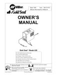
Gold SealTM Model 5000
CV/DC Welding Power Source/Wire Feeder
For FCAW
Rated
Welding Or GMAW Welding
Output
Of 70
Uses 115 VAC
Amperes
With
Optional Gas
At 16 Volts DC, 20%
Single-Phase Input
Valve
Duty Cycle
Power
Motor Overload Protection
Basic Model Includes Gun, Standard Model Adds Gas Valve,
Deluxe Model Adds Gas Regulator/Flowmeter
Read and follow these instructions and all
safety
blocks
Have
only
trained
install, operate,
or
and
8/92
ST.161 158
Give this manual to the operator.
qualified persons
service this unit.
Call your distributor if you do not understand
the directions.
cover
U
carefully.
For
or:
help,
call your distributor
MILLER ELECTRIC
Mfg. Co.,
1079, Appleton, WI 54912
P.O. Box
414-734-9821
PRINTED IN USA
-
F
U
J
MILLERS
TRUE BLUETM LIMITED WARRANTY
EffectIve
(Equipment
This limited werrenty
a
January 1, 1992
preface of
serial number
supersedes sit previous MILLER warrentlas end
to the terms end conditions
WARRANTYSubject
Mlg. Co., Appleton, Wioconain,
LIMITED
with
werrents to its
is eaclunive with no other
below, MILLER Electric
retell purcheser thet
original
new
MILLER equipment sold elfer the effective dete of this limited werrenty is free of de
tects in meteriel end workmanship et the time it is shipped by MILLER. THIS WAR
RANTY IS EXPRESSLY IN LIEU OF ALL OTHER WARRANTIES, EXPRESS OR
or
gusrentees
Acceeeory Kite
*
Replecement Perle
True
BtuenM
Iteme furnished
1.
newer)
*
MILLERS
IMPLIED, INCLUDING THE WARRANTIES OF MERCHANTABILITY AND FIT
NESS.
KC
or
Limited
warrenflea espreseed
Werrenty shell
werrenty periods listed below,
MILLER will
repeir
or
replece eny
provide instructions
on
the
werrenty cleim procedures
end
to be
3.
on
the dete thet the
equipment
wee
delivered to the
originel
retell
Originel
en contect
tips, culling nozzles, contectore
hen been modified
by eny perty other then MILLER. or equip
improperly inetelled, improperly opereted or mIsused
induetry etenderde, or equipment which hee not hed reeeonebte
based upon
purcheser,
equipment which hoe been
end neceeeery meintenence,
or
outside of the
for the
epeciticetione
used for
operetlon
equipment.
MILLER PRODUCTS ARE INTENDED FOR PURCHASE AND USE BY COMMER
CIAtJINDUSTRIAL USERS AND PERSONS TRAINED AND EXPERIENCED IN
THE USE AND MAINTENANCE OF WELDING EOUIPMENT.
mein power rectifiers
Perts end Lebor
3 Yeers
2.
es engines or
by the menufeclurers werrenty, If
ment thet hee been
3 Yeers Lebor
S Yeers Perts
covered
releye.
Equipment thet
end ere es follows:
t.
ere
Coneumeble components; euch
2.
MILLER shell honor werrenty ctelme on werrented equipment listed below in the
event of such e teilure within the werrenty time periods. All werrenty time periods
stert
to:
eny.
wer
rented perle or components thet tell due to such defects in meteriel or workmanship.
MILLER must be notified in writing within thirty (30) deys of such detect or teiture, et
which time MILLER will
followed.
epply
Implied.
by MILLER, but menufectured by others, such
trede ecceeeoriee. These items
Within the
not
or
In the event of e
werrenty claim covered by this werrenty. the eecluslve remedies
be, et MILLERS option: II) repeir; or 12) replecement; or, where euthorlzed In
writing by MILLER in eppropriete ceees, )3) the reesoneble cost of repelr or replece
ment at en euthorized MILLER service stetlon; or (4) peyment of orcredlt for the pur
chase price (less reesonebte deprecietion besed upon ectuel use) upon return of the
goode et customers risk end espenee. MILLERS option of repeir or reptecement
will be FOB., Fectory at Appleton, Wisconsin, or FOB. et e MILLER euthorlzed ser
vice facility es determined by MILLER. Therefore no compensetion or reImburse
ment for transportation costs of eny kind wilt be ellowed.
Treneformer/Rectilier Power Sources
Plesme Arc
*
Cutting
shell
Power Sources
Semi-Autometic end Autometic Wire Feeders
Robots
Perte end Lebor
2 Yeers
3.
Engine Driven Welding Generet ore
)NOTE: Engines em werrented eeperetely by
1 Yeer
4.
the
engine menufecturer.)
TO THE EXTENT PERMITTED BY LAW, THE REMEDIES PROVIDED HEREIN
ARE THE SOLE AND EXCLUSIVE REMEDIES. IN NO EVENT SHALL MILLER BE
LIABLE FOR DIRECT, INDIRECt SPECIAL, INCIDENTAL OR CONSEOUENTIAL
DAMAGES (INCLUDING LOSS OF PROFIT). WHETHER BASED ON CON
TRACT, TORT OR ANY OTHER LEGAL THEORY.
Perte end Lebor
Motor Driven Guns
*
Process Controllers
Water Coolent
Systems
HF Unite
*
ANY EXPRESS WARRANTY NOT PROVIDED HEREIN AND ANY IMPLIED WAR
Grids
Spot
RANTY, GUARANTY OR REPRESENTATION AS TO PERFORMANCE, AND ANY
REMEDY FOR BREACH OF CONTRACT TORT OR ANY OTHER LEGAL
THEORY WHICH, BUT FOR THIS PROVISION, MIGHT ARISE BY IMPLICATION,
OPERATION OF LAW, CUSTOM OF TRADE OR COURSE OF DEALING, IN
CLUDING ANY IMPLIED WARRANTY OF MERCHANTABILITY OR FITNESS
FOR PARTICULAR PURPOSE, WITH RESPECT TO ANY AND ALL EOUIPMENT
FURNISHED BY MILLER IS EXCLUDED AND DISCLAIMED BY MtLLER.
Welders
Loed Benko
*
SDX Trenetormern
Running Geer/Treilere
Options
*
*
Field
(NOTE: Field options ere covered under True BIaenM for the remeining
werrenty period of the product they ere inatelled in, or for e minimum of
whichever in greeter.)
one yeer
S.
6 Months
6.
90
Deye
Some otetee in the U.S.A. do not allow Ilmitetions of how
lesto,
cific
Bell eries
Perle end Lebor
MIG Gune/TIG Torches
Culling
Pleeme
*
Remote Controls
long
en
implIed werrenty
the eaclusion of incidentel. indirect. opeciel or consequentlel demeges, so
or eaciusion may not apply to you. This werrenty provides spe
legal rights,
end other
In
Canada, legislation in
or
remedies other than
rights
some
as
may be available, but may vary from state to state.
provinces provides for
certain additional warranties
staled herein. and to the entent that
they may
not be
waived, the limitations and eaclusione eat out abova may not apply. ThIs Limited
Warranty provides specific legal rights, and other rights may be available, but may
vary 1mm province to province.
Torches
*
or
the ebove limitation
4>
al-
RECEIVING-HANDLING
unpack)ng equipment, ChBCk carton for any damage that may haVB occurred dUr)ng shipment. File any C)aimS for )oss or damage
delivering carrier, Assistance for filing or setthng c)aims may be obta)ned from distributor and/or equipment manufacturers
Transportation Department.
Before
with the
When
requesting
Use the
or
following
information about this
equipment, always provide Mode) Designation and Serial
spaces to record Model
Designation
and Serial
or
Style Number of your unit.
or
Style
Number.
The information is located
on
the
rating
label
nameplate.
Model
_________
Serial
or
Style
No.
Date of Purchase
miller 5/92
ARC WELDING SAFETY PRECAUTIONS
Read all
all
Obey
safety messages throughout this manual.
safety messages
Learn the
1
meaning
to avoid
injury.
of WARNING and CAUTION.
2
1
Safety
2
SignalWord
2
\
Alert
WARNING
A~ WARNING
I
a CAUTION
3
______________
ELECTRIC SHOCK
~
can
kill
Do not touch live electrical parts.
Disconnect
installing
or
input power
servicing.
1…~I.
h
J~j
before
~
or
MOVING PARTS
Keep
all panels
operating.
and
covers
closed
possible death
happen.
can
means possible minor
injury or equipment damage can
happen.
Keep away tram moving parts.
when
means
injury
CAUTION
I
Injure.
can
serious
Symbol
I
/
3
Statement Of Hazard And
Result
4
Safety
5
Instructions To Avoid
Hazard
READ SAFETY BLOCKS at start of
Section 3-1 before proceeding.
V
6
I
5
Hazard
6
Safety Banner
Read
7
~
Turn Off switch when
using high frequency.
NOTE
Special instructions for best
ation
not related to safety.
WARNING
A~
blocks for each sym.
bol shown.
_____
NOTE
safety
Symbol (If Available)
ARC WELDING
can
oper
be hazardous.
PROTECT YOURSELF AND OTHERS FROM POSSIBLE SERIOUS INJURY OR DEATH. KEEP CHILDREN
AWAY. PACEMAKER WEARERS KEEP AWAY UNTIL CONSULTING YOUR DOCTOR.
In welding, as in most jobs, exposure to certain hazards occurs. Welding is safe when precautions are taken. The
safety information given below is only a summary of the more complete safety information that will be found in the
Safety Standards listed on the next page. Read and follow all Safety Standards.
HAVE ALL
INSTALLATION, OPERATION, MAINTENANCE, AND REPAIR WORK PERFORMED ONLY BY
QUALIFIED PEOPLE.
ELECTRIC SHOCK
can
kill.
5.
Touching live electrical parts can cause fatal shocks
or severe burns. The electrode and work circuit is
electrically live whenever the output is on. The input
power circuit and machine internal circuits are also
live when power is on. In semiautomatic or automatic
wire welding, the wire, wire reel, drive roll housing,
and all metal parts touching the welding wire are
electrically live. Incorrectly installed or improperly
grounded equipment is a hazard.
1.
Do not touch live electrical parts.
2.
Wear
3.
Insulate
dry,
hole-free
yourself
insulating gloves and body protection.
ground using dry insulating
Disconnect
input power
servicing this equipment.
/~p~
~2
-
or
stop engine before installing
install and
Manual and national, state, and local codes.
6.
Turn oft all
7.
Do not
cables.
ground
equipment
use
worn,
this
equipment according
when not in
Do not wrap cables around your
body.
9.
Ground the
electrical
workpiece
good
to a
or
poorly spliced
(earth) ground.
10.
Do not touch electrode while in contact with the work
circuit.
11.
Use only well-maintained equipment.
damaged parts at once.
12.
Wear
a
safety
harness to
to its
use.
damaged, undersized,
8.
from work and
mats or covers.
4.
Properly
Owners
Repair
or
(ground)
replace
prevent falling if working above floor
level.
or
13.
Keep
all
ARC RAYS can burn eyes and skin;
NOISE can damage hearing.
1.
Wear
a
Arc rays from the welding process produce intense
heat and strong ultraviolet rays that can burn eyes
and skin. Noise from some processes can damage
2.
Safety Standards) to protect your face and
eyes when welding or watching.
Wear approved safety glasses. Side shields recommended.
3.
Use
hearing.
panels
welding
and
covers
securely
helmet fitted with
a
in
place.
proper shade of filter
(see
ANSI Z49.1 listed in
and
4.
5.
protective
screens or
barriers to protect others from flash
glare; warn others not to watch the arc.
Wear protective clothing made from durable, flame-resistant
material (wool and leather) and foot protection.
Use approved ear plugs or ear muffs if noise level is high.
FUMES AND GASES
5.
be hazardous
can
Welding produces fumes and gases. Breathing these
fumes and gases
6.
1.
2.
3.
4.
Safety
Data Sheets
(MSDSs)
and the
instruction for metals, consumables,
coatings,
Read the Material
7.
weld area, the
Watch for fire, and
Be
and others from
(10.7 m) of the welding arc. If
this is not possible, tightly cover them with approved covers,
Be alert that welding sparks and hot materials from welding can
easily go through small cracks and openings to adjacent areas,
can
FLYING SPARKS AND HOT METAL
cool, they
and
cause
throw off
CYLINDERS
fire
keep
welding
on
a
fire
on a
extinguisher nearby.
ceiling, floor, bulkhead,
partition
.
Connect work cable to the work as close to the welding area as
practical to prevent welding currentfrom traveling long, possibly
Do not
11.
on
closed containers such
paths and causing electric
use
welder to thaw frozen
tip
when not in
Wearoil-free
Wear
tanks
or
drums.
shock and fire hazards.
or
cut off
wire at
welding
use.
protective garments such as leather gloves, heavy
shirt, cuffless trousers, high shoes, and
1.
as
pipes.
Remove stick electrode from holder
contact
can
or
the hidden side.
approved face shield
or
a
cap.
safety goggles. Side
shields
recommended.
grinding
can
is well ventilated, and if necessary, while
8.
injury,
Chipping
spraying
Do not weld
10.
Remove all flammables within 35 ft
cause
or
with vapors to
7.
9.
strike flammable material.
Do not weld where
that
can cause
and hot metal.
2.
flying sparks
aware
unknown
.
flying sparks
3.
4.
area
6.
yourself
can react
wearing an air-supplied respirator. The coatings and any metals
containing these elements can give off toxic fumes if welded.
fire,
Protect
the
on coated metals, such as galvanized, lead, or
plated steel, unless the coating is removed from the
5.
or
sure
Do not weld
explosion.
fire
can cause
degreasing, cleaning,
near
The heat and rays of the arc
toxic and irritating gases.
Sparks and spatter fly off from the welding arc. The
flying sparks and hot metal, weld spatter, hot
workpiece, and hot equipment can cause fires and
burns. Accidental contact of electrode orwelding wire
to metal objects can cause sparks, overheating, or
WELDING
while
or
used for
air is safe.
Do not weld in locations
cadmium
and cleaners.
1.
an
operations.
form highly
Keep your head out of the fumes. Do not breath the fumes.
If inside, ventilate the area and/or use exhaust at the arc to
remove welding fumes and gases.
If ventilation is poor, use an approved air-supplied respirator.
manufacturers
only if it is well ventilated,
air-supplied respirator. Shielding gases
can displace air causing injury or death. Be
confined space
a
breathing
be hazardous to your health.
can
Work in
wearing
welding
to your health.
can
2.
metal. As welds
flying
Wear proper
body protection
to
protect skin.
slag.
explode
if
3.
damaged.
from any
Keep cylinders away
welding
other electrical
or
circuits.
Shielding gas cylinders contain gas under high
pressure. If damaged, a cylinder can explode. Since
gas cylinders are normally part of the welding
process, be sure to treat them carefully.
4.
5.
6.
1.
Protect
2.
cylinders in
them to a stationary support
prevent falling or tipping.
secure
an
or
excessive
7.
upright position by chaining
equipment cylinder rack to
8.
gas cylinders
mechanical shocks, and arcs.
Install and
from
heat,
compressed
a welding electrode to touch any cylinder.
only correct shielding gas cylinders, regulators, hoses, and
fittings designed for the specific application; maintain them and
associated parts in good condition.
Turn face away from valve outlet when opening cylinder valve.
Keep protective cap in place over valve except when cylinder is
Never allow
Use
in use or connected for
use.
Read and follow instructions
associated
equipment,
compressed gas cylinders,
publication P-i listed in Safety
on
and CGA
Standards.
PRINCIPAL SAFETY STANDARDS
Safety
in
Welding
and
Cutting, ANSI Standard Z49.1,
Safetyand Health Standards,
OSHA 29 CFR 1910, from
Recommended Safe Practices for the
Society
from American
Welding Society,
Superintendent of Documents,
550 N.W. LeJeune Rd, Miami FL 33126
U.S. Government
Preparation for Welding and Cutting of Containers That Have Held Hazardous Substances,
Standard AWS F4.1, from American
Welding Society,
Handling
of Compressed Gases in
American
20402.
Welding
550 N.W. LeJeune Rd, Miami, FL 33126
National Electrical Code, NFPA Standard 70, from National Fire Protection Association,
Safe
Printing Office, Washington, D.C.
Cylinders, CGA Pamphlet P-i,
from
Batterymarch Park, Quincy,
Compressed Gas Association,
MA 02269.
1235 Jefferson Davis
Highway, Suite
501, Arlington, VA 22202.
Code for
Safety in Welding and Cutting, CSA Standard
Wi 17.2, from Canadian Standards
Association, Standards Sales, 178 Rexdale Boulevard,
Rexdale, Ontario, Canada M9W 1 R3.
Safe Practices For Occupation And Educational Eye And Face Protection, ANSI Standard Z87. 1 ,from American National Standards Institute, 1430
Broadway,
Cutting
New York, NY 10018.
And
Welding Processes,
NFPA Standard 51
B, from National Fire Protection Association, Batterymarch Park, Quincy, MA 02269.
TABLE OF CONTENTS
SPECIFICATIONS
SECTION 1
1-1.
Volt-Ampere Curve And Duty Cycle Chart
1
SECTION 2INSTALLATION
2-1.
2-2.
2-3.
2-4.
2-5.
2-6.
Installing Work Clamp
Polarity For Wire Type
Installing Welding Gun
Connecting Input Power
Threading And Feeding Welding
Installing Gas Supply
2
Gun
2
3
3
Wire
.
SECTION 3OPERATION
3
5
6
SECTION 4- MAINTENANCE & TROUBLESHOOTING
4-1.
Overload Protection
4-2.
Drive
4-3.
Gun Maintenance
4-4.
Troubleshooting
7
Assembly Maintenance
10
SECTION 5
ELECTRICAL DIAGRAMS
SECTION 6
PARTS LIST
Figure
Figure
Figure
6-1. Main
6-2. Drive
Assembly
Assembly,
6-3. GA-i 6C1 Gun
8
9
11
13
Wire
15
16
OM.1 57 745
4/93
SECTION 1
SPECIFICATIONS
Table 1-1.
Welding
Power Source
Description
Specifications
Type
Of
Constant
Output
Rated Weld
Output
Type Of Input
70
At Rated
Output
Welding
Voltage
29 Volts DC
24 Volts DC
At Gun
(FCAW)
Flux Cored Arc
Processes
Speed Range
60 Hz; At 115 Volts AC
2.2 kVN2 kW
Open-Circuit Voltage
Control Circuit
22 To 286
At No Load
ipm (0.6
(0.58
Overall Dimensions
Length: 16-1/2
in
Weight
Net: 53 lb
Range
And Gas Metal Arc
To 7.3
.023 To .035 in
Wire Diameter
(CV/DC)
15 A
KVA/KW Used At Rated Output
Max.
Current
Amperes, 16 Volts DC, 20% Duty Cycle
Single-Phase;
Power
Input Amperes
Voltage/Direct
To 0.89
mm)
(419 mm); Width: 9-1/2
(24 kg); Ship:
Welding (GMAW)
mpm)
65 lb
in
(241 mm); Height:
17 in
(432 mm)
(29 kg)
Welding Gun
Rated
Output (Air Cooled)
160
Cable
Length
10 ft
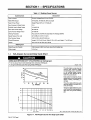
1-1.
Curve And
Volt-Ampere
Amperes At 60% Duty Cycle Using CO2 Shielding Gas
(3 m)
Duty Cycle Chart
CAUTION
a
U SING GUN BEYOND DUTY CYCLE RATING
Do not
use
beyond
gun
Use gun at 30%
duty cycle
when
using
mixed
can
using CO2
rated amperage when
damage gun.
shiel ding gas.
shielding gas.
~arn8.1 10/91
The volt-ampere curves show the
minimum and maximum voltage
30
and amperage output capabilities
of the welding power source.
25
20
Curves of other
settings
fall be
tween the curves shown.
15
Duty cycle is how long the unit can
operate within a ten minute period
g
without
5
causing overheating
or
damage.
0
This unit is rated at 20% duty cycle
allowing welding 2 minutes out of
every 10 minutes.
DC AMPERES
This gun is rated at 60% duty cycle
when using CO2 shielding gas and
30% when
using
mixed
shielding
gas.
I0
5
20
30
25
DUTY
Figure
OM-157 745
Page
1
1-1.
CYCt.E
40
50
60
70
80
90
00
ssbl.1 10/91 /sbl.3 10/91 SB-157
~
Volt-Ampere Curve
And
Duty Cycle
Chart
146/SB.121 475
SECTION 2
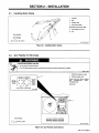
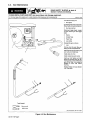
2-1.
Work
Installing
INSTALLATION
Clamp
1
Insulator
2
Bolt
3
Smaller Hole
4
Work
Clamp
Tabs
Bend tabs around work cable.
5
Work Cable From Unit
6
Nut
Tools Needed:
~ 3/8, 7/16
in
Ret. ST-025 190-C
Figure
2-2.
Gun
Polarity
For Wire
2-1.
Installing
Work
Clamp
Type
WARNING
a
ELECTRIC SHOCK
can
Do not touch live electrical
Turn Oft
welding
kill.
parts.
power source, and disconnect
input
power before
inspecting
or
installing.
SwOrnl.1 2/93
1
~
For Flux
Cored Wires
(FCAW
Processi
J
~
L
STRAIGHT
POLARITY
~
I
REVERSE
POLARITY
~{~
I
For Solid
Steel Or
Aluminum
L
DCEN
Polarity Changeover
Polarity Jumper Links
Always
wire
mended
Wires
S.~.P
1
2
IGMAWI
Processi
read and follow
manufacturers
Label
welding
recom
polarity.
Close door.
OCEP
GUN POLARITY CHANGEOVER
S-116
599-Cl
2
Tools Needed:
C~~~JzztC
C
I
)1
~) I
1 I
_______
1
1
1
1
-
3/8 in
Ref. ST-159 619-A
Figure
2-2. Gun
Polarity Connections
OM-157 745
Page
2
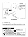
Installing Welding
2-3.
Gun
1
Gun
2
Drive
3
Gun End
Loosen
Securing
Nut
Assembly
bottoms
securing nut. Insert end
panel opening until it
against drive assembly.
Tighten
nut.
through
4
front
Gun
Trigger
Insert leads,
grommet
leads to
on
one
Leads
at
front
matching
a
time, through
panel. Connect
leads in unit.
Close door.
Tools Needed:
~ 5/l6in
Ref. ST.159 619-A/ Ret. ST-159 216
Figure
2-4.
Connecting Input
2-3. Gun Connections
Power
Connect unitto a properly grounded 115 VAC receptacle of a 20 ampere individual branch circuit protected bytime-delay
or circuit breakers. Select an extension cord of 12 AWG for up to 75 ft (23 m) or 10 AWG for up to 140 ft (46 m).
fuses
2-5.
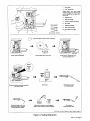
Threading
a
And
Feeding Welding
Wire
WARNING
ELECTRIC SHOCK
can
kill.
Do not touch live electrical
parts.
welding wire, drive rolls, drive assembly, and all
metal parts touching the welding wire are electrically
live when welding or feeding wire using gun trigger.
S
The
WELDING WIRE
wounds.
Do not press gun
can
trigger
cause
S
so.
~
.~_
-
~
Donotpointguntowardanypartofthebody,other
people, or any metal when threading welding wire.
can
burn skin.
can
Allow gun to cool before
C YLINDERS
puncture
until instructed to do
HOT SURFACES
touching.
explode
Keep cylinders away
from
if
damaged.
welding
and
other
electrical circuits.
Never touch
cylinder
with
Always secure cylinder
other stationary support.
welding electrode.
to
running gear, wall,
or
swarn5.1 10/91 / swarn2.1 9/91
OM-157 745
Page
3
Spool
1
Wire
2
Hub Tension Nut
Grasp spool. Turn
wrench to adjust nut.
while
using
slight
spool, ten
When
force is needed to turn
sion is set.
2
3
Tools Needed:
3
Welding
4
Inlet Wire Guide
5
Pressure
6
Drive Roll
7
Outlet Wire Guide
8
Gun Conduit Cable
Lay gun
a
Wire
Adjustment
cable out
Knob
straight.
~ 9/l6in
Hold wire
tightly
to
keep
it from
unraveling.
6
4
(150 mm)
Open
pressure
assembly.
in~
(102 mm)
Pull and hold wire; cut off end.
Push wire thru guides into gun;
continue to hold wire.
ON
POWER
-*=~
00FF
Close and
1111
Press gun
trigger
until wire
out of gun. Reinstall
contact tube and nozzle.
comes
Remove gun nozzle
and contact tube.
Set switch.
tighten pressure assembly,
and let go of wire.
II
-~
Feed wire to check drive roll pressure.
lighten knob enough
to
~~r~J/
Cut off wire.
Close and latch door.
prevent slipping.
Ref. ST-161 157/ Ret. ST-159 615-Al Ret. ST.159 216 / S-0627-A
Figure
2-4.
Feeding Welding Wire
OM-157 745
Page
4
2-6.
Installing Gas Supply
£~
WARNING
CYLINDERS
can
explode if damaged.
Keep cylinders away
from
welding
and
other
electrical circuits.
Never touch
BUILDUP OF SHIELDING GAS
health or kill.
Shut off
cylinder
with
Always secure cylinder
other stationary support.
welding
to
shielding gas supply
can
when not in
harm
use.
electrode.
running gear, wall,
or
warn4.1 9/91
Obtain gas
cylinder and chain to
running gear, wall, or other station
ary support so cylinder cannot fall
and break off valve.
1
Cap
2
Cylinder
Valve
Remove
cap, stand to side of
and open valve slightly. Gas
flow blows dust and dirt from valve.
valve,
Close valve.
3
3
CO2 Cylinder
4
0-Ring
5
Regulator/Flowmeter
If not
supplied,
obtain proper regu
use with CO2
lator/flowmeter for
gas. Install onto gas
cylinder
so
that face is vertical.
Flow rate for
6
supplied regulator/
(cubic
flowmeter is set to 20 cfh
feet per hour).
6
Gas Rose Connection
Tools Needed:
Obtain and install gas hose.
1-1/8,5/8 in
ssb31* 12/92
Figure
OM-157 745
PageS
2-5. Installation Of Deluxe Model
Regulator/Flowmeter
ST-154 583 / ST-154 823
SECTION 3
a
WARNING
OPERATION
READ SAFETY BLOCKS at beginning
of manual before proceeding.
=~
MOVING PARTS
can cause
Keep away from pinch points
Keep all doors, panels,
securely in place
ARCING
injury.
such
covers, and
as
guards
damage
switch.
Do not
closed
and
1
can
change ThicknessNoltage switch position
while welding.
Arcing inside switch can damage contacts, causing
drive rolls.
switch to fail.
3
2
/
~S8
1
Insulating Gloves
2
Safety Glasses
With Side
Shields
3
Welding
Helmet
Wear
dry insulating gloves, safety
glasses with side shields, and a
welding helmet with a correct
shade of filter (see ANSI Z49.1).
sb3.1 10/91
Figure
3-1.
Safety Equipment
1
Power Switch
Use switch to turn unit On and Off.
2
Wire
Speed Control
Use control to select
a
wire feed
speed. As Voltage switch setting
increases, wire speed range also
increases. The numbers around
the control
are
speed (see
rear
3
not
a
wire feed
cover).
ThicknessNoltage
Use switch to select
Switch
an arc
voltage.
Use Low to weld thin materialand
High
rear
to weld thicker material
(see
cover).
Use wire brush or sandpaper to
clean metal at weld joint area. Use
chipping hammer
welding.
to remove
slag
after
Connect
work
paint-free
as
close
clamp
location
as
on
possible
to
clean,
workpiece,
to weld
area.
5T-159 017 I Ret. ST-157 049
Figure
3-2. Controls
OM-157 745 Page 6
SECTION 4- MAINTENANCE& TROUBLESHOOTING
-
WARNING
A~
ELECTRIC SHOCK
can
M OVING PARTS
kill.
Turn Oft
welding power source, and disconnect
input power before inspecting, maintaining, or
servicing.
HOT PARTS
Allow
can cause severe
cooling
servicing.
period
before
can cause
injury.
Keep away from moving parts.
Do not touch live electrical parts.
4f
Keep away from pinch points
such
as
drive rolls.
burns.
maintaining
or
Maintenance and
only by qualified
troubleshooting
to be
persons.
performed
swarnS 2
2/93
Table 4-1. Maintenance Schedule
Maintenance
Time
Before each
After each
Tighten
use.
spool
of wire.
all connections. Check gun and clean nozzle.
Blow out gun liner. Clean and check wire drive
Every
3 months.
Tape
Every
6 months.
Blow out
4-1.
or
replace
cracked cables: clean and
or vacuum
parts; replace
as
necessary.
tighten connections. Replace
unreadable labels.
inside of unit.
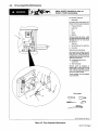
Overload Protection
READ SAFETY BLOCKS at start of
Sectio n 4 before proceeding.
A.
Overheating
Thermostat TP1 protects the unit from damage due to overheating. If main transformer Ti gets too hot, TPi opens and
weld output stops. The fan keeps running to cool the transformer. Wait several minutes before trying to weld.
B.
Motor Fuse Fl
Turn Off and
unplug
door,
handle, and
remove
unit. Unlatch
remove
door/wrapper.
1
Fuse Fl
(See
Parts List For
Rating)
If this fuse opens, the wire drive
motor does not run.
Push
on
open.
Replace fuse.
fuseholder and twist to
Reinstall wrapper and handle, and
latch door.
Tools Needed:
1T~~1ZJfl
1/4,3/Bin
ST-159 618 / Ret. ST-I 52 031
Figure
OM-157 745
Page
7
4-1.
Fuse Fl Location
4-2.
Drive
Assembly
Maintenance
I~4s.
7
READ SAFETY BLOCKS at start of
Section 4 before proceeding.
______
Turn Off and
1
Wire
Cut
welding
unit.
unplug
Spool
wire off at contact tube.
Retract wire onto
spool
2
Pressure Roll Arm
3
Cotter Pin
4
Pin
5
Screw
6
Bearing
and
secure.
Remove
bearing as shown. Install
bearing and secure with screw.
Reinstall arm onto pin and secure
new
with cotter
pin.
7
Setscrew
8
Smooth Groove For Hard Wire
9
Drive Roll
Remove drive roll
as
shown.
Use
a wire brush to clean drive roll.
Push drive roll onto shaft with de
sired groove in. Turn drive roll so one
setscrew faces flat side of shaft, and
both setscrews.
tighten
10
Knurled Groove For FluxCored Wire
11
Wire Inlet Guide
Remove
guide
by pressing on
cutting oft one end
near housing and pulling it out of
hole. Push new guide into hole from
rear until it snaps in place.
barbed
area or
Thread
welding
wire
(see Section
2-5). Close door.
Tools Needed:
5/6~1
Ret. ST-159 615-A / ST-154 199
Figure
4-2. Drive
Assembly
Maintenance
OM-157 745
Page
8
4-3.
Gun Maintenance
READ SAFETY BLOCKS at start of
Section 4 before proceeding.
1
FLYING METAL CHIPS AND DIRT
Point gun away from
people
and in
a
can cause
safe direction when
injury
blowing
and
damage equipment.
out with
compressed air.
swarrilOl 10/91
Turn Off and
Wire
1
unplug
unit.
Spool
Cut welding wire off at contact tube.
Retract wire onto spool and secure.
Gun Securing Nut
2
Disconnect trigger leads. Loosen
nut and
leads.
remove
3
Nozzle
4
Contact Tube
5
Head Tube
6
Liner Collet
Disassemble gun
gun and trigger
as
shown.
Liner
7
Pull liner from this end. Blow gun
out with compressed air.
casing
Insert
2
even
new
liner into gun
casing until
with end of head tube.
Install collet onto liner.
Install contact tube and nozzle.
Insert gun into feeder and mark
where liner touches drive roll. Re
move gun and cut liner off. Reinstall
gun so that liner is as close as
possible to drive rolls without
3
touching.
4
Thread welding wire (see Section
2-5). Close door.
5
7
Tools Needed:
3/8, 5/16 in
Rot. 57-159 619-A / Rot. ST-155 509
Figure
OM-157 745
Page
9
4-3. Gun Maintenance
4-4.
Troubleshooting
READ SAFETY BLOCKS at start of
Section 4 before proceeding.
Table 4-2.
Welding
Trouble
Welding
Trouble
No weld output; wire does not
Section
Remedy
fee~
-,
Secure power cord
Motor fuse Fl open,
Replace building
Secure gun
No weld output; wire does not feed; fan
motor continues to run, and pilot light
--
in
plug
replace fuse.
line fuse
trigger
receptacle.
leads
or
or
reset circuit breaker if open.
repair leads,
or
replace trigger
-~
2-4
-~
~
--
switch.
--
2-3
-a
Thermostat TP1 open (overheating). Allow fan to run; the thermo
stat will close when the unit has cooled.
4-lA
turns off.
No weld output; wire feeds.
---p.
Connect work
Replace
to
get good metal-to-metal
H
contact.
Figure 3-2
contact tube.
-ru-~ Connect
Low weld output.
clamp
unit to proper
4-3
input voltage
or
check for low line
--L
voltage.
2-4
Table 4-3. Wire Drive/Gun Trouble
Wire Drive/Gun Trouble
Electrode wire
feeding stops during
Section
Remedy
-~
Straighten
gun cable and/or
replace damaged parts.
-~
4-3
welding.
Adjust
drive roll pressure.
Readjust
2-5
hub tension.
2-5
Replace
contact tube if blocked.
Clean
replace
or
Replace
wire inlet
drive roll
or
guide
pressure
Secure gun
trigger
leads
Check and
replace
Fl.
or
or
liner if
bearing
if
repair leads,
Factory
or
worn or
or
plugged.
4-3
-~
4-2,4-3
slipping.
4.2
replace trigger switch.
2-3
-~
Check and clear any restrictions at drive
Have nearest
dirty
-~
assembly and liner.
Authorized Service Station check drive
4-lB
4-2,4-3
---~
--
motor.
OM-157 745 Page 10
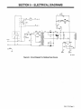
SECTION 5- ELECTRICAL DIAGRAMS
CR I
2
I
z
L
PLC I
69N.
ST-157 378
Figure
5-1. Circuit
Diagram For Welding
Power Source
OM-157 745
Page
11
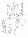
379-A
~~1
--j
SC-157
P2
CORD
POWER
Source
GND
SPLIcE
Power
Welding
For
Diagram
Wiring
5-2.
Figure
WORK
8A(FM-2~V.)
S2
SI
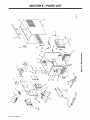
SECTION 6
PARTS LIST
C0
>
E
a,
U,
U,
4
(a
a)
L.
IL.
c~:J
C,,
CD
Lf)~
LI~
OM-157 745
Page
13
Part
No
Description
-
Mkgs.
Figure
1
010909..
2
3
010910..
073355..
4
111998..
5
111929..
6.... CR1
120706..
7
120675..
8....
FM
111931..
9
005656..
10
053297..
Fl
11
*012663..
12.... VR1
087156..
13
R2
117116..
14
Ci
109039..
15
161439..
16
108105..
17
134834..
18
149322..
29.... GS1
116996..
120077..
20
157190..
Ri
21
119653..
605227..
22
23
157187..
24
089899..
157376..
25
26
134464..
+157188..
27
28
PLG1
113494..
29
111644..
30
31
019663..
....
32
TP1
120638..
Ti
157389..
33
34
Z
35
36
37
6-1. Main
Assembly
NUT, SB slflkg hex .375-16
WASHER, flatstl SAE .375
SPRING, cprsn .625 OD x .093 wire x 1 .000
PIN, cotter hair .l2Odia x 2.375 Ig x .500 shaft
HUB, spool
RELAY, end 24VAC DPDT
BRACKET, mtg motor fan
MOTOR, fan 115V 50/60Hz 2600RPM .i8i8dia shaft
BLADE, fan 6 in 4wg 3odeg .175 bore CW
HOLDER, fuse crtg in-line
FUSE, mintr gI slo-blo 3A
1
2
1
1
1
1
1
1
1
VARISTOR, 10 joule 68VDC
RESISTOR, WWfxd 20W 50 ohm
CAPACITOR, elctlt 46000uf 35VDC
1
1
1
STRIP, comb rmr .012 x 1.500 x 9.000
CLAMP, capacitor 2.500dia
HOSE, SAE .187 ID x .410 OD (order by ft)
CLAMP, hose .405-.485clp dia slfttng
VALVE, 115VAC 2 way custom port 1/8 orf (std & deluxe model)
BLANK, snap-in nyl sq 1.250 (basic model only)
CASE SECTION, front/base/rear
RHEOSTAT, WW 25W 25 ohm
NUT, nyl hex jam .75ONPST (std & deluxe model)
PANEL, side
LATCH, slide
HANDLE, lifting
LABEL, warning general precautionary
S2
39
.40
41
42
Si
44
..45....SR2....
46
..47....TE1....
48
49
1
3ft
2
1
1
1
1
1
1
WRAPPER
1
CORD SET, 125V 5-15P l4ga 3/c 7ft
BUSHING, strain relief .370/430 ID x .875mtg hole
MOUNT, nprn 15/16 OD
THERMOSTAT, NC
1
4
1
1
157447..
TRANSFORMER, pwr main 115 (consisting of)
COIL, pwr main
118457..
STABILIZER
1~
1
CLAMP, grd 200A
BUSHING, strain relief .240/.510 ID x .875mtg hole
157305.. SWITCH, rocker DPDT 15A 125VAC
600 325.. CABLE, weld cop strd No. 6 (order by ft)
026 843.. INSULATOR, vinyl blk
119 697.. GA-l6Ci GUN, (Fig 6-3)
025 338.. BUSHING, nyl univ 23/32 hd dia .625mtg hole
097 922.. KNOB, pointer
153 698.. SWITCH, rocker SPST 16A 125VAC
NAMEPLATE, (order by model and serial number)
119 264.. RECTIFIER, si iph 100A 200PIV
010 047.. TUBING, stl .625 OD x 1 2ga wall x 1.000
122 385.. TERMINAL ASSEMBLY, chgov (consisting of)
601 835.... NUT, brs hex 10-32
038 887.... STUD, pri bd brs 10-32 x 1.375
010368..
111443..
38
.43
Quantity
~
Dia.
Item
No.
1
1
1 5ft
2
1
1
1
1
1
1
1
8
4
50
.116620....
51
038618....
2
52
157 191
LINK, jumper term bd pri
BAFFLE,air
1
53
131 336..
ASSEMBLY, wire (Fig 6-2)
CLIP, component .437dia mtg adh back
REGULATOR/FLOWMETER, dual scale (deluxe model only)
FITTING, brs barbed M 1/4tbg x 1/4NPT (deluxe model only)
1
..
059 712..
153 714..
602 958..
*Recommended
Spare
+When
a
ordering
TERMINALBOARD,chgov
1
DRIVE
1
1
Parts.
component originally displaying
a precautionary label, the label should also be ordered.
BE SURE TO PROVIDE MODEL AND SERIAL NUMBER WHEN ORDERING REPLACEMENT PARTS.
OM-157 745
Page
14
Item
No.
Dia.
Part
No.
Mkgs.
131 336
..1..MOT..
119 021
..2
604 657
.5
602 213
010 910
128 189
..6
602 211
.7
604 538
..8
10
129 893
126 838
090 416
11
124 817
12
13
151 828
112 031
14
090 443
15
114 415
16
010 224
17
058
085
085
090
092
602
604
605
18
19
20
21
22
23
24
549
242
244
415
237
204
537
853
25
119 028
26
602 169
27
28
601 862
602 203
29
604 673
Quantity
Description
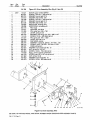
Figure
6-2. Drive
Assembly,
Wire
(Fig
MOTOR, gear 12VDC 80RPM
SCREW, .375-16 x 1.250 hexhd sti
WASHER, lock stl split .375
WASHER,fIatstlSAE.375
SCREW, .312-18 x 1.750 hexhd sti
WASHER, lock stl split .312
WASHER,flatstlSAE.312
INSULATOR, housing drive
WIRE DRIVE, (consisting of)
PIN, hinge
HOUSING, wire drive
PIN, cotter hair .042 x .750
LEVER, pressure roll
BEARING, ball rdl sgl row .315 x .866
SCREW, 10-24 x .625 flathd-phl stl
6-1 Item
x
53)
.447
1
PIN, spring CS .187 x 1.000
GUIDE, wire inlet 1/16
FASTENER, pinned
WASHER, cupped stl .328 ID x .812 OD x .125
SPRING, cprsn .720 OD x .072 wire x 1.250
KNOB, adj tension
WASHER, lock stl ext tooth No. 10
1
1
1
1
1
3
NUT, stl hex full .312-18
1
SCREW, 10-32 x .750 rndhd-slt stl
ROLL, drive V groove combination
SCREW, set 8-32 x .187 cup pt sch stl
NUT, stl hex 10-32
WASHER, lock sti split No. 10
SCREW, 10-32 x .625 flathd-slt sti
3
1
2
1
1
1
5
2.
7
8
12
16
13
14
18-
15
28
Figure
6-2. Drive
Assembly,
27
22
26
25
24
7
Wire
BE SURE TO PROVIDE MODEL AND SERIAL NUMBER WHEN ORDERING REPLACEMENT PARTS.
OM-157 745
Page
15
SC.121 448.C
Itern
No.
Part
No.
Figure
119 697
1
110793..
2
110 795
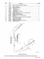
6-3. GA-16C1 Gun
(Fig
4
5
110 781
6
6-1 Item
40)
HANDLE ASSEMBLY
TUBE, head (consisting of)
110780.... NUT, MiOxi
110 779
JACKET, head tube
3
Quantity
Description
..
....
....
128 878
....
7
110 782
....
8
110786
....
.110789..
10.. .110794..
11
080565..
..12.. ...110797..
.13..
120714..
.14..
120715..
15..
079974..
16.. ...110796..
.17..
047994..
.18.. ...110792..
STOP, nozzle
ADAPTER, head tube/nozzle
SPRING, nozzle
TUBE contact 030
wire
(quantity
of 1 included with
gun)
3
NOZZLE, slip type 1/2 orE
1
TRIGGER SWITCH ASSEMBLY
TERMINAL, frict fern .110 x .016 22-18 wire
SLEEVE, rbr
2
1
1
LINER, rnonocoil .030-.035 wire w/collet lOft (consisting of)
COLLET, liner .035 wire
0-RING, .500 ID x .1O3CS rbr
1
1
2
CONNECTOR, gun/feeder
TERMINAL, frict fern .250
x
1
2
.032 22-18 wire
CABLE/CONDUIT, lOft
1
9
2
10
12
11
17
18
Figure
Ref. SC-lb
832-0
6-3. GA-16C1 Gun
BE SURE TO PROVIDE MODEL AND SERIAL NUMBER WHEN ORDERING REPLACEMENT PARTS.
OM-157 745
Page
16
thicker
+
mm)
in
and
ga
0.1046 (2.65
HIGH
90
HIGH
60
12
in
ga
14-13
mm)
0.74-89
0.538-67 (1.36-1.7
0.359-478
(1.89-2 8 MEDIUM
Not
Recomnd Recomnd
MEDIU/HG
Not
50
MEDIUM
40
MEDIUM
40
MEDIUM
30
MEDIUM
95
LOW
60
LOW
50
LOW
60
LOW
30
LOW
25
LOW
55
100
in
ga
Thicknes
17-15
mm)
in
Material
STE L
MILD
WELDING
FOR
PARMETS
SUGETD
ga
20-18
mm)
-1.21
(0.91
in
Than mm)
0. 359
Thin er
ga
(0.91
20
CONTRL SETINGS Voltage Adjustmen FWeired Adjustmen Control Voltage Adjustmen FWeired Adjustmen Control Voltage Adjustmen FWeired Adjustmen Control
SHIELDNG
2
GAS
NA
OUT
in
1/2
STICK
WELDING POLARITY SETINGS
NA
mm)
in
1/2
(12.7
DCEN
CO
mm)
1/4
(12.7
DCEN
PROCES
0
0
-.4
01
-4
mm) Cored
0.030 (0.76 Flux
in
FCAW
E-71TGS
in
mm) Cored
0.035 (0.8 9 Flux
FCAW
(6.35
DCEP
in
SIZE TYPE
WIRE AND
mm)
in
E-71TGS
mm)
0.23- 5 (0.58- 64
GMAW
Ste l
Solid
696
S-157
Ref.