1
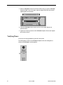
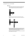
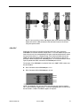
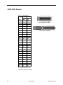
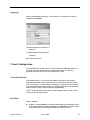
AIM29000-48 Interface Module Installation Instructions Document Number AIM2-A2-GZ41-00 January 2006 Contents Software and Firmware License Agreement ...................................................... 2 Product Documentation Online .......................................................................... 3 Release Notes ................................................................................................... 3 Warranty, Sales, Service, and Training Information ........................................... 3 AIM29000 Description ....................................................................................... 4 Unpacking and Inspecting the AIM29000 .......................................................... 4 Installing the AIM29000 in a BLC ...................................................................... 4 Verifying Power .................................................................................................. 6 Connecting the ADSL Cables ............................................................................ 7 ADSL Remote Connection ................................................................................. 11 ADSL RJ21 Pinouts ........................................................................................... 12 Verify the ADSL Connection(s) .......................................................................... 13 LED Indicators ................................................................................................... 13 ADSL Parameters .............................................................................................. 14 AIM29000 Management .................................................................................... 14 Circuit Configuration .......................................................................................... 15 Other Configuration Options .............................................................................. 20 Data Storage ...................................................................................................... 21 Firmware Upgrades ........................................................................................... 22 Regulatory Compliance for Class A Equipment ................................................. 23 Specifications ..................................................................................................... 24 AIM2-A2-GZ41-00 January 2006 1 Software and Firmware License Agreement ONCE YOU HAVE READ THIS LICENSE AGREEMENT AND AGREE TO ITS TERMS, YOU MAY USE THE SOFTWARE AND/OR FIRMWARE INCORPORATED INTO THE PARADYNE PRODUCT. BY USING THE PARADYNE PRODUCT YOU SHOW YOUR ACCEPTANCE OF THE TERMS OF THIS LICENSE AGREEMENT. IN THE EVENT THAT YOU DO NOT AGREE WITH ANY OF THE TERMS OF THIS LICENSE AGREEMENT, PROMPTLY RETURN THE UNUSED PRODUCT IN ITS ORIGINAL PACKAGING AND YOUR SALES RECEIPT OR INVOICE TO THE LOCATION WHERE YOU OBTAINED THE PARADYNE PRODUCT OR THE LOCATION FROM WHICH IT WAS SHIPPED TO YOU, AS APPLICABLE, AND YOU WILL RECEIVE A REFUND OR CREDIT FOR THE PARADYNE PRODUCT PURCHASED BY YOU. The terms and conditions of this License Agreement (the “Agreement”) will apply to the software and/or firmware (individually or collectively the “Software”) incorporated into the Paradyne product (the “Product”) purchased by you and any derivatives obtained from the Software, including any copy of either. If you have executed a separate written agreement covering the Software supplied to you under this purchase, such separate written agreement shall govern. Paradyne Corporation (“Paradyne”) grants to you, and you (“Licensee”) agree to accept a personal, non-transferable, non-exclusive, right (without the right to sublicense) to use the Software, solely as it is intended and solely as incorporated in the Product purchased from Paradyne or its authorized distributor or reseller under the following terms and conditions: 1. Ownership: The Software is the sole property of Paradyne and/or its licensors. The Licensee acquires no title, right or interest in the Software other than the license granted under this Agreement. 2. Licensee shall not use the Software in any country other than the country in which the Product was rightfully purchased except upon prior written notice to Paradyne and an agreement in writing to additional terms. 3. The Licensee shall not reverse engineer, decompile or disassemble the Software in whole or in part. 4. The Licensee shall not copy the Software except for a single archival copy. 5. Except for the Product warranty contained in the manual, the Software is provided “AS IS” and in its present state and condition and Paradyne makes no other warranty whatsoever with respect to the Product purchased by you. THIS AGREEMENT EXPRESSLY EXCLUDES ALL OTHER WARRANTIES, WHETHER EXPRESS OR IMPLIED, OR ORAL OR WRITTEN, INCLUDING WITHOUT LIMITATION: a. Any warranty that the Software is error-free, will operate uninterrupted in your operating environment, or is compatible with any equipment or software configurations; and b. ANY AND ALL IMPLIED WARRANTIES, INCLUDING WITHOUT LIMITATION IMPLIED WARRANTIES OF MERCHANTABILITY, FITNESS FOR A PARTICULAR PURPOSE AND NON-INFRINGEMENT. Some states or other jurisdictions do not allow the exclusion of implied warranties on limitations on how long an implied warranty lasts, so the above limitations may not apply to you. This warranty gives you specific legal rights, 2 January 2006 AIM2-A2-GZ41-00 and you may also have other rights which vary from one state or jurisdiction to another. 6. In no event will Paradyne be liable to Licensee for any consequential, incidental, punitive or special damages, including any lost profits or lost savings, loss of business information or business interruption or other pecuniary loss arising out of the use or inability to use the Software, whether based on contract, tort, warranty or other legal or equitable grounds, even if Paradyne has been advised of the possibility of such damages, or for any claim by any third party. 7. The rights granted under this Agreement may not be assigned, sublicensed or otherwise transferred by the Licensee to any third party without the prior written consent of Paradyne. 8. This Agreement and the license granted under this Agreement shall be terminated in the event of breach by the Licensee of any provisions of this Agreement. 9. Upon such termination, the Licensee shall refrain from any further use of the Software and destroy the original and all copies of the Software in the possession of Licensee together with all documentation and related materials. 10. This Agreement shall be governed by the laws of the State of Florida, without regard to its provisions concerning conflicts of laws. Product Documentation Online Complete documentation for Paradyne products is available at www.paradyne.com. Select Support → Technical Manuals. To order a paper copy of a Paradyne document, or to speak with a sales representative, please call 1-727-530-2000. Release Notes Release notes for this product are available in the subscriber firmware area of www.paradyne.com. Select Support → Subscriber Firmware. Always review the relevant release notes before installing a new card. Warranty, Sales, Service, and Training Information Contact your local sales representative, service representative, or distributor directly for any help needed. For additional information concerning warranty, sales, service, repair, installation, documentation, training, distributor locations, or Paradyne worldwide office locations, use one of the following methods: Internet: Visit the Paradyne World Wide Web site at www.paradyne.com. (Be sure to register your warranty at www.paradyne.com/warranty.) Telephone: Call our automated system to receive current information by fax or to speak with a company representative. — Within the U.S.A., call 1-800-870-2221 — Outside the U.S.A., call 1-727-530-2340 AIM2-A2-GZ41-00 January 2006 3 AIM29000 Description The AIM29000-48 is a 48-port ADSL2+ Annex A or Annex B inverse multiplexer. It occupies a slot in a Model 4000 or 12000 Broadband Loop Carrier (BLC). Unpacking and Inspecting the AIM29000 HANDLING PRECAUTIONS FOR ! STATIC-SENSITIVE DEVICES This product is designed to protect sensitive components from damage due to electrostatic discharge (ESD) during normal operation. When performing installation procedures, however, take proper static control precautions to prevent damage to equipment. If you are not sure of the proper static control precautions, contact your nearest sales or service representative. If there is visible damage, do not attempt to connect the device. Contact your service or sales representative. Installing the AIM29000 in a BLC There must be a management module, complete with an uplink module, installed in your BLC in order for the AIM29000 to operate. NOTE: All of Paradyne’s BLC IP interface modules are hot swappable. Installing or removing an interface module while the chassis is powered up does not affect the operational status of other interface modules within the chassis. 12-Slot BLC The 12000 and 12000E BLCs are fourteen slot chassis. Slots 1–12 are reserved for interface modules (such as the AIM29000), and the remaining slots (13 and 14 in the 12000 and U1 and U2 in the 12000E) are reserved for management modules. NOTE: Although the AIM29000 can be installed in both the 12000 and the 12000E BLC, the 12000 has the capability to support AIM29000 ports 1–24 only. In order to make use of all 48 ports, you must install the AIM29000 in a 12000E. Procedure To install the AIM29000 in a 12-slot BLC: 1. Select a slot for installation. The AIM29000 may be placed in any available slot, 1–12. Remove the cover plate from the chosen slot by turning the fastening screws counterclockwise with a screwdriver and then gently sliding the cover plate out of the chassis. CAUTION: If a cover plate is removed from slot 1–12 of a 12000 or 12000E BLC, it must be replaced with an interface module. Do not operate your BLC with an empty slot. 4 January 2006 AIM2-A2-GZ41-00 2. With the AIM29000 Printed Circuit Board (PCB) facing right and the AIM29000 model name on the lower edge of the faceplate, align the upper and lower edges of the PCB with the slot module guides. 3. Slide the AIM29000 into the chassis until it is fully seated. Do not use excessive force. 4. Tighten the fastening screws on the AIM29000 faceplate by turning them clockwise with a screwdriver, just until snug. Do not over-tighten the fastening screws. 4-Slot BLC The 4000 and 4000E are five-slot chassis. Slots 1–4 are reserved for interface modules (such as the AIM29000), and the remaining slot (slot 5 in the 4000 and slot U1 in the 4000E) is reserved for a management module. NOTE: Although the AIM29000 can be installed in both the 4000 and the 4000E BLCs, the 4000 has the capability to support AIM29000 ports 1–24 only; in order to make use of all 48 ports, you must install the AIM29000 in a 4000E. Procedure To install the AIM29000 in a 4-slot BLC: 1. Select a slot for installation. The AIM29000 may be placed in any slot, 1–4. Remove the blank plate from the chosen slot by turning the fastening screws counter-clockwise with a Phillips screwdriver and then gently sliding the blank plate out of the chassis CAUTION: If a blank plate is removed from slot 1–4 on a 4000 or 4000E BLC, it must be replaced with an interface module. Do not operate your BLC with an empty slot. AIM2-A2-GZ41-00 January 2006 5 2. With the AIM29000 Printed Circuit Board (PCB) facing up and the AIM29000 faceplate model name on the right, align the edges of the PCB with the slot module guides on both sides. 3. Slide the AIM29000 into the chassis until it is fully seated. Do not use excessive force. 4. Tighten the fastening screws on the AIM29000 faceplate. Do not over-tighten the fastening screws. Verifying Power If you have not already powered up your BLC, do so now. The PWR (power) LED on the AIM29000 faceplate illuminates solid green to indicate the AIM29000 is receiving power. 6 January 2006 AIM2-A2-GZ41-00 Connecting the ADSL Cables 12-Slot BLC NOTE: No configuration is necessary for the AIM29000 to operate at default settings. However, if you wish to run your subscriber connections at settings other than the factory defaults, configure the AIM29000 prior to ADSL connection. Refer to AIM29000 Management on page 14 for further information. Subscriber lines must be connected according to the BLC slot in which the AIM29000 was installed. Interface module slots 1–12 run from left to right when you are facing the front of the chassis; the corresponding RJ21 ports are directly behind each slot on the back of the chassis (1–12, right to left, when you are facing the back of the chassis). Each interface module slot on the 12000E has two corresponding female RJ21 connectors: the bottom row of connectors (A) provides the ADSL connection for AIM29000 ports 1–24 and the top row of RJ21 connectors (B) provides the ADSL connection for ports 25–48. For example, if the AIM29000 is installed in Slot 3 of a 12000E, ADSL cables must be connected to: RJ21 Connector 3B for AIM29000 ports 25–48 RJ21 Connector 3A for AIM29000 ports 1–24 NOTE: The 12000 has only one RJ21 connector for each interface module slot. These connectors support ports 1–24 of the AIM29000; ports 25–48 cannot be connected in a 12000. The 12000E supports all 48 ports. AIM2-A2-GZ41-00 January 2006 7 Attaching RJ21 Connectors to the 12-Slot BLC Procedure 1. Detach the hook and loop fastener strap from the RJ21 receptacle. Lift the hook and loop fastener tab on the left and pull the strap open towards the right, leaving it looped under the right side of the connector frame. 2. Slide the RJ21 plug of your ADSL cable underneath the hook and loop fastener from the bottom, and press it firmly into the RJ21 receptacle on the chassis. 3. Pull the hook and loop fastener strap to the right, making sure that it is snug against the connector, then pull the strap back towards the left, such that the hook and loop fastener layers stick to one another across the top of the connector. Tuck the tab at the end of the strap down to the left of the connector frame so that it is out of the way of other connections. 4. Screw the top of the RJ21 cable connector into the jackscrew at the top of the RJ21 connector frame on the chassis. 8 January 2006 AIM2-A2-GZ41-00 NOTE: If you are using a 120 or 180 degree cable, fasten both the top and the bottom of the RJ21 cable connector to the connector frame on the chassis using the captive screws. 4-Slot BLC Subscriber lines must be connected according to the BLC slot in which the AIM29000 was installed. Interface module slots 1–4 run from bottom to top on the front of the chassis; the corresponding RJ21 ports are directly behind each slot on the back of the chassis (1–4, bottom to top). Each interface module slot on the 4000E has two corresponding RJ21 connectors: the connectors on the left (A) provide the ADSL connection for AIM29000 ports 1-24 and the connectors on the right (B) provide the ADSL connection for AIM29000 ports 25–48. For example, if the AIM29000 is installed in Slot 3 of a 4000E, ADSL cables must be connected to: RJ21 Connector 3A for AIM29000 ports 1–24 RJ21 Connector 3B for AIM29000 ports 25–48 NOTE: The 4000 BLC has only one RJ21 connector for each interface module slot. These connectors support ports 1–24 on the AIM29000; ports 25–48 cannot be connected in a 4000. The 4000E supports all 48 ports. AIM2-A2-GZ41-00 January 2006 9 Attaching RJ21 Connectors to the 4-Slot BLC Procedure 1. Detach the hook and loop fastener strap from the female RJ21 connector port: lift the hook and loop fastener tab from the bottom and pull the strap open, towards the top of the chassis, leaving it looped under the top side of the connector frame. 2. Slide the male RJ21 connector of your ADSL cable underneath the hook and loop fastener, from the left, and press it firmly into the female RJ21 connector port on the chassis. 3. Pull the hook and loop fastener strap upward, making sure that it is snug against the connector, then pull the strap back down, such that the layers stick to one another across the top of the connector. Tuck the tab at the end of the strap down between the connector frames so that it is out of the way of other connections. 10 January 2006 AIM2-A2-GZ41-00 4. Screw the right side of the RJ21 cable connector into the jackscrew on the right side of the RJ21 connector frame on the chassis. NOTE: If you are using a 120 or 180 degree cable, fasten both the top and the bottom of the RJ21 cable connector to the connector frame on the chassis using the captive screws. ADSL Remote Connection A single line connection can be established between any port on the AIM29000 and any compatible G.lite, ADSL, ADSL2, or ADSL2+ modem. AIM2-A2-GZ41-00 January 2006 11 ADSL RJ21 Pinouts Table 1. RJ21 Pinouts Pin Port Ring Tip 1 1 26 2 2 27 3 3 28 4 4 29 5 5 30 6 6 31 7 7 32 8 8 33 9 9 34 10 10 35 11 11 36 12 12 37 13 13 38 14 14 39 15 15 40 16 16 41 17 17 42 18 18 43 19 19 44 20 20 45 21 21 46 22 22 47 23 23 48 24 24 49 RJ21 Connector on BLC RJ21 Cable Connector (Pins 25 and 50 are not used) 12 January 2006 AIM2-A2-GZ41-00 Verify the ADSL Connection(s) The LK (Link) LED for each port being connected to a remote modem illuminates solid green to indicate a connection has been established. Link up time between the AIM29000 and remote modems can vary from 15 seconds to five minutes depending on the quality, gauge, and distance of the copper cable pair or pairs being used. LED Indicators Table 2. LEDs LED State Indication Additional Information PWR (Power) Solid Green AIM29000 is receiving power If the Power LED is not illuminated, it is likely the AIM29000 is not receiving power, in which case none of the LEDs will be illuminated. ADSL LK (Link) Solid Green ADSL connection is established The ADSL link is operational. No Illumination No ADSL connection The ADSL Rx and Tx LEDs will remain unlit by default. Fashing Amber ADSL activity The port is transmitting or receiving data from the remote ADSL modem. Solid Amber Heavy traffic The port is transmitting or receiving large amounts of data from the remote ADSL modem. No Illumination No activity A link may exist but the port is not transmitting or receiving any data from the remote ADSL modem. ADSL ACT (Activity) AIM2-A2-GZ41-00 January 2006 13 ADSL Parameters No configuration is necessary for the AIM29000 to operate at the default settings. Table 3. AIM29000 Defaults Parameter Default Backbone-VLAN 0 Downstream Speed n/a (Adaptive Port Mode) Flood Uplink Frame Type 1483LLC IP Range 1 0.0.0.0 – 255.255.255.255 IP Range 2-4 0.0.0.0 – 0.0.0.0 Port Mode Adaptive Protocol All Standard Mode Multimode Upstream Speed n/a (Adaptive Port Mode) Virtual Channel Identifier (VCI) 35 Virtual Path Identifier (VPI) 0 VLAN 0–0 VLAN Priority 0 VPI/VCI Detect On AIM29000 Management All parameters on the AIM29000 are software selectable. Dependent upon the management module installed in your BLC, the AIM29000 can be configured via the Command Line Interface (CLI), Simple Network Management Protocol (SNMP), or the web-based Network Management System (NMS). The NMS is recommended, since it is the most capable and easiest to use. Management Via The NMS The NMS is an embedded web server that resides within the firmware of BLC management modules. This web server maintains statistical and configurational data for the AIM29000. NOTE: If your BLC is newly installed and has not yet been initialized, you must configure the IP Address, Subnet Mask and Gateway before you will be able to access data or complete any other configurations. Refer to the NMS Management User’s Guide at www.paradyne.com for instructions. 14 January 2006 AIM2-A2-GZ41-00 Logging In Open an NMS window and log on. You must log on as a Superuser in order to configure the AIM29000. The default Superuser username is: superuser The default Superuser password is: Password Both are case sensitive. Circuit Configuration From the NMS main window, click on any one of the port LEDs depicted on the hardware image to invoke the Circuit Configuration screen. The following parameters may be set on the Circuit Configuration screen. Circuit Identification Circuit Identification is a unique and searchable 15-character, alphanumeric, user-defined identifier used to label each port. If the Circuit ID entered is longer than 15 characters, it is automatically truncated to 15. Typically, service providers use a corresponding customer number or circuit ID number from their Operations Support System (OSS) in order to facilitate troubleshooting. NOTE: The Circuit Identification field is not yet integrated with any OSS system and is currently for reference only. Port Mode Default: Adaptive AIM2-A2-GZ41-00 Adaptive – An AIM29000 port set to port mode adaptive will automatically train up to the best possible speed supported by the AIM29000, the ADSL modem at the remote end, and the copper cable pair connecting the two. January 2006 15 Fixed – An AIM29000 port set to port mode fixed will maintain consistant upstream and downstream bandwidths as specified by the user. The link is lost if the speed cannot be maintained. Fixed Adaptive – An AIM29000 port set to port mode fixed adaptive will automatically train up to the best possible speed supported by the AIM29000, the ADSL modem at the remote end, and the copper cable pair connecting the two, within the confines of user-specified maximum upstream and downstream bandwidths. The modems will train at a lower speed if line conditions deteriorate. Off – An AIM29000 port set to port mode off has been administratively turned off. Filter IP Address Settings IP Range 1 Default: 0.0.0.0 – 225.255.255.255 IP Range 2–4 Default: 0.0.0.0 – 0.0.0.0 IP Range filtering is user-defined via configurable starting and ending IP addresses that specify an acceptable range of source IP addresses for incoming packets. Up to four IP ranges may be configured per port in the NMS, and up to two IP ranges may be configured per port via the CLI or SNMP. Single IP Address Starting IP Address = Ending IP Address An AIM29000 port configured with a single source IP address will only allow packets with that specific IP address to traverse the port. IP Address Range Starting IP Address < Ending IP Address An AIM29000 port configured with a source IP address range will allow packets having an IP address within the specified range to traverse the port. Full IP Address Range Starting IP Address = 0.0.0.0 Ending IP Address = 255.255.255.255 An AIM29000 port configured with the full range of source IP addresses will allow packets with any source IP address to traverse the port. Rate Limit Default Ingress Limit: 0 Default Egress Limit: 0 Rate limiting restricts the bandwidth of incoming or outgoing unknown unicast, unknown multicast, and broadcast traffic. Specify a rate in kbps for ingress and egress packets. 16 January 2006 AIM2-A2-GZ41-00 DHCP Option 82 Default: Disabled NOTE: DHCP Option 82 is available for configuration in NMS only; it cannot be configured via the CLI or SNMP. Dynamic Host Configuration Protocol (DHCP) Option 82 allows dynamic configuration of IP addresses by adding an identifying string to packets (Option 82) that enables your DHCP Server to recognize which BLC port an IP address request is coming from. This allows the DHCP Server to limit the number of IP addresses assigned per port according to the DHCP Server configurations. PVC Settings ADSL data travels by way of Asynchronous Transfer Mode (ATM) cells across Permanent Virtual Circuits (PVCs). Each PVC consists of one Virtual Channel across one Virtual Path as identified by a Virtual Channel Identifier (VCI) and a Virtual Path Identifier (VPI). Configuration of PVCs allows for the categorization of traffic by type (such as video or voice) by assigning a separate PVC to each Ethernet port (up to four) on a remote modem. To configure PVC Indexes, you must first deactivate the VPI/VCI Detect parameter (see VPI/VCI Detect, below). The default is ON, whereby the selected port will automatically monitor the line to determine the VPI and VCI settings of the remote ADSL modem to which it is connected and set itself accordingly on PVC 1. If no ATM cells are detected (at any VPI/VCI setting), the port will default to VPI 0 and VCI 35. Thereafter, once it does detect ATM cells from the remote ADSL modem, it will reconfigure VPI and VCI to the same settings at which the ATM cells from the remote ADSL modem were detected. With the VPI/VCI Detect Setting at off, the selected port will default to VPI 0 and VCI 35 on PVC 1 unless the port was previously set at VPI/VCI Detect on and had already detected the VPI and VCI settings of the remote ADSL modem. In this case, turning the VPI/VCI function off will lock in the previously detected settings unless the VPI and VCI values are altered manually. Once the VPI/VCI Detect Setting has been turned off, you will be able to manually configure the VPI and VCI settings for up to four PVC Indexes (numbered 1–4) in the same ADSL Circuit Configuration window. Each index must be assigned the same VPI and VCI values as the port on the remote ADSL modem to which that index will be assigned in order for traffic to traverse the line successfully. The pull-down PVC Index menus may now be used to select a PVC Index for each of the rules you configure. NOTE: PVC Indexes will only be applied to packets coming in through a subscriber connection (WAN). They are not applicable to packets coming in through an uplink connection. VPI/VCI Detect Default: On ADSL data travels by way of Asynchronous Transfer Mode (ATM) cells across Permanent Virtual Circuits (PVCs). Each PVC consists of one Virtual Channel across one Virtual Path as identified by a Virtual Channel Identifier (VCI) and a AIM2-A2-GZ41-00 January 2006 17 Virtual Path Identifier (VPI). A VPI is designated by an 8-bit field in ATM cell headers and a VCI is designated by a 16-bit field in ATM cell headers. The AIM29000 supports one PVC per port. On – An AIM29000 port with VPI/VCI Detect on will automatically monitor the line to determine the VPI and VCI settings of the remote ADSL modem to which it is connected, and set itself accordingly. If no ATM cells are detected (at any VPI/VCI setting), the port will default to VPI 0 and VCI 35. Thereafter, once it does detect ATM cells from the remote ADSL modem, it will reconfigure VPI and VCI to the same settings at which the ATM cells from the remote ADSL modem were detected. Off – An AIM29000 port with VPI/VCI Detect off will default to VPI 0 and VCI 35 unless the port was previously set at VPI/VCI Detect on and had already detected the VPI and VCI settings of the remote ADSL modem. In this case, turning the VPI/VCI Detect function off will lock in the previously detected settings unless the VPI and VCI values are altered manually. Manual – If you wish to set VPI and VCI values manually, VPI/VCI Detect should be set to off defore the VPI and VCI values are entered. When manually configuring VPI and VCI, each port on the AIM29000 must be assigned the same VPI and VCI values as the remote ADSL modem to which that port is connected in order for the units to communicate. Protocol Setting Default: Allow All Traffic protocol is indicated by a 2-byte (hexadecimal) Ethertype code in packet headers. Allow All – An AIM29000 port configured with Protocol All will allow packets with all Ethertype protocols to traverse the port. Allow Selected or Disallow Selected – You can specify up to four Ethertype protocols. If Allow Selected is active, only packets with the specified Ethertypes will be allowed to traverse the port. If Disallow Selected is active, packets with the specified Ethertypes will not be allowed to traverse the port. The port is automatically set to accept 0800 (IP) and 0806 (IP ARP) packets. NOTE: Not all BLC management modules provide the Protocol Select option in NMS, and the Select option is not available via CLI or SNMP. In these instances you will be required to choose between All or IP, where IP indicates that only Transmission Control Protocol (TCP), Internet Protocol (IP) and Address Resolution Protocol (ARP) traffic will be allowed to traverse the port. Layer 2 Port Filter Settings Default: Inactive Select the checkbox next to Layer 2 Port Filter Settings if you want to control traffic according to MAC addresses. MAC 1, MAC 2, MAC 3 Specify up to three MAC addresses permitted to traverse the port. 18 January 2006 AIM2-A2-GZ41-00 Unlimited # of MACs Select the check box next to Unlimited # of MACs to limit the number of different MAC addresses permitted to use the port. Define # of MACs Select the check box next to Define # of MACs to limit the MAC addresses permitted to access the port to a specific quantity. Frame Type Default: 1438LLC Frame type is the ADSL data encapsulation method for carrying traffic over an ATM network as defined by the Internet Engineering Task Force (IETF) Request for Comment (RFC) 1483. 1438LLC – An AIM29000 port configured with Logical Link Control (LLC) encapsulation multiplexes multiple protocols over a single ATM Vitual Circuit by way of the protocol-identifying frame header 1438LLC. 1483VCM – An AIM29000 port configured with Virtual Circuit Multiplexing (VCM) creates a separate ATM Virtual Circuit connection for each protocol type, without additional encapsulation, by way of the protocol-identifying frame header 1438VCM. Standard Mode Default: Multimode Alcatel – Alcatel is ADSL technology and Alcatel ADSL modem compatible. Full Rate ADSL – An AIM29000 port that is operating in full rate ADSL mode and utilizing a single line for both phone and data requires an in-line splitter at both ends of the ADSL connection. Full Rate ADSL2 – An AIM29000 port that is operating in full rate ADSL2 mode and utilizing a single line for both phone and data requires an in-line splitter at both ends of the ADSL2 connection. NOTE: The Full Rate ADSL2 options (G.DMT.BIS, G.DMT.BISplus and READSL2) are not yet available for configuration via the CLI or SNMP; these standard modes are configurable via the NMS only. AIM2-A2-GZ41-00 G.DMT – G.DMT is ADSL technology in compliance with the standards of ITU-T Recommendation G.992.1. The AIM29000 exceeds the ITU-T G.992.1 minimum requirements of 640 kbps upstream and 6,000 kbps downstream speeds in G.DMT mode. G.DMT.BIS – G.DMT.BIS is ADSL2 technology in compliance with the standards of the International Telecommunications Union Telecommunication Standardization Sector (ITU-T) Recommendation G.992.3, which specifies a downstream frequency range of 1100 kHz. G.DMT.BISplus – G.DMT.BISplus is ADSL2+ technology in compliance with the standards of ITU-T Recommendation G.992.5, which specifies a downstream frequency range of 2200 kHz. January 2006 19 G.lite – G.lite is ADSL technology in compliance with the standards of ITU-T Recommendation G.992.2. The AIM29000 meets the ITU-T Recommendation G992.2 minimum requirements of 512 kbps upstream and 5,136 kbps downstream speeds in G.lite mode. An AIM29000 port that is operating in G.lite mode and utilizing a single line for both phone and data requires an in-line splitter at the local end, and a microfilter at the remote end, of the ADSL connection. Multimode – An AIM29000 port set to multimode detects and matches the standard mode of the remote ADSL modem to which it is connected. READSL2 – Reach Expanded ADSL2 is ADSL2 technology in compliance with the standards of ITU-T Recommendation G.992.3 in Annex L format. T1.413 – T1.413 is ADSL technology in compliance with the standards of the American National Standards Institute (ANSI) Standard T1.413. Bandwidth and Distance The default bandwidth for AIM29000 ADSL connections is Adaptive as defined in Port Mode on page 15. The eventual outcome could be any combination of existing possible upstream and downstream bandwidths, and may or may not be reflected in the following tables. For AIM29000 ports configured at Fixed or Fixed Adaptive port modes, bandwidth parameters must be manually specified. Other Configuration Options In addition to Circuit Configuration, the following tabs are available on the configuration screens: DSCP Rules IP Rules MAC Rules VLAN Rules Port Statistics Port Copy SNR Advanced Configuration See the Multimedia Traffic Management User’s Guide and NMS User’s Guide for information. 20 January 2006 AIM2-A2-GZ41-00 Data Storage Configuration backup is inherent in the AIM29000. Upon initial power up of the host BLC, default parameters of the AIM29000 will remain in place unless changed through the NMS, CLI, or SNMP. Memory AIM29000 parameter configurations are automatically recorded in both the Random Access Memory (RAM) of the AIM29000 and the Non-Volatile Random Access Memory (NVRAM) of the BLC's management module. RAM Statistical data stored only in AIM29000 RAM, such as traffic statistics and link up/down time, will be erased if the module is removed from the BLC or the BLC loses power. NVRAM AIM29000 data stored in the BLC's management module NVRAM, such as port parameter configurations, will remain intact (even if the BLC loses power) unless deliberately cleared or reconfigured. Uploading a Port Template AIM29000 port configurations can be flash uploaded from your BLC management module to a file on your PC or local network via a Trivial File Transfer Protocol (TFTP) tool and a get command. A port template file contains all of a selected port's configurations except Circuit ID. Table 4. TFTP Requirements AIM2-A2-GZ41-00 Item Data Needed for Backup Example Host Name DSLAM IP Address (xxx.xxx.xxx.xxx) 193.166.254.98 Remote Filename Nvr_PortCfg.Bin."Superuser password".[slot][port] nvr_portcfg.bin.Password.[2][10] Local Filename User Preference Adsl_ServiceLevel_4_template.bin January 2006 21 Downloading a Port Template AIM29000 configuration files can also be flash downloaded from a local file to your BLC's management module via a TFTP tool using a put command. A previously saved port configuration file can be applied to multiple ports on your AIM29000 simultaneously, via your BLC management module, by entering the port value as follows. Table 5. Specifying Multiple Ports for a TFTP Download Method of Entry EXAMPLE: nvr_portcfg.bin.Password.[slot][ports] Comma-separated list nvr_portcfg.bin.Password.[2][10,12,20,45,] Dash-indicated range nvr_portcfg.bin.Password.[2][10-45] Keyword “all” nvr_portcfg.bin.Password.[2][all] Refer to your TFTP user manual for further instruction. Firmware Upgrades Create a BLC back-up file prior to downloading any new firmware revisions. Refer to the Firmware Upgrade Procedure (document number FUP-A2-GK40) for instructions. All registered customers automatically receive notification of new firmware versions and accompanying documentation. New firmware versions can be downloaded from Paradyne’s website a Trivial File Transfer Protocol (TFTP) tool. 22 January 2006 AIM2-A2-GZ41-00 Regulatory Compliance for Class A Equipment The following regulatory information applies to the AIM29000 as installed in a BLC. NEBS: GR-63-CORE, GR-1089-CORE EMC: FCC Part 15; CSA/C108.8; EN55022, EN55024 SAFETY: UL 60950-1 1st Edition, UL Marking; CSA 22.2 No. 60950-1-03; EN60950-1:2001, CE Marking TELECOM: ACTA968 (Part68); ICCS-03; TBR12 and TBR13 US Federal Communications Commission (FCC) This equipment has been tested and found to comply with the limits for a Class A digital device, pursuant to part 15 of the FCC Rules. These limits are designed to provide reasonable protection against harmful interference when the equipment is operated in a commercial environment. This equipment generates, uses and can radiate radio frequency energy and, if not installed and used in accordance with the instruction manual, may cause harmful interference to radio communications. Operation of this equipment in a residential area is likely to cause harmful interference in which case the user will be required to correct the interference at his own expense. Caution: Changes or modifications not expressly approved by the manufacturer could void the user's authority to operate the equipment. Industry Canada This Class A digital apparatus complies with Canadian ICES-003. Cet appareil numérique de la Classe A est conforme à la norme NMB-003 du Canada. Europe This Class A product complies with European Norm EN55022. Warning: In a domestic environment this product may cause radio interference in which case the user may be required to take adequate measures to correct the situation. AIM2-A2-GZ41-00 January 2006 23 Specifications Table 6. AIM29000 Specifications Specification Criteria Dimensions 12.75" High x 1.15" Wide x 16.75" Deep (32.4 cm x 2.9 cm x 42.5 cm) Environment Operating Temperature: 32°F to 122°F (0°C to 50°C) in a 12000 BLC –40°F to 149°F (–40°C to 65°C) in a 4000 BLC· Storage Temperature: –40°F to 158°F (–40°C to 70°C)· Humidity: 5% to 95%, non-condensing· Altitude: –200 ft to 16,500 ft (–60 m to 5,000 m) Power –48 VDC (supplied by the host BLC)· 1.6 amps Weight 3.6 lbs (1.6 kg) *AIM2-A2-GZ41-00* *AIM2-A2-GZ41-00* Copyright 2005 Paradyne Corporation. Printed in U.S.A. 24 January 2006 AIM2-A2-GZ41-00