1
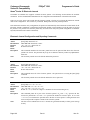
POSjet® 1500
PROGRAMMER‟S
GUIDE
PN: 20-03398
Rev N
Nov-2010
Programmer’s Guide
POSjet® 1500
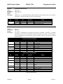
General Information
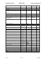
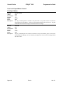
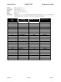
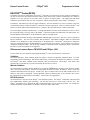
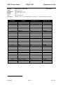
Change Log
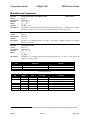
Rev A
Rev B
Rev C
Rev D
Never Released
Nov 2001 Initial Release
Jan 2002
1)
Corrected the Auto Journal Documentation
2)
Corrected the [ESC]f Quick Reference listing.
3)
Fixed the OCR listing. (The wrong font was used to print this in some versions of the manual.)
4)
Corrected some spelling errors.
5)
Corrected the description of the EPOS Emulation [GS]0<Name…> <m> command
6)
Added Page mode minimum size restrictions
7)
Added more detail to several IPCL command descriptions.
8)
Clarified the Epson [GS]k command
9)
Added Journal features to the Epson [ESC]v command.
Nov 2002
1)
Corrected Pass through documentation.
2)
Added Coupon-Cut-Logo feature.
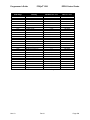
Rev E
Feb 2003
1)
Updated disclaimer
Rev F
March 2003
1)
Fixed hex and decimal description of the [ESC][EM]L command
2)
Removed ASB. It is now a special order option
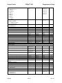
Rev G
October 2003
1)
Added slip detection documentation.
2)
Added a validation right sensor operation modification command.
Rev H
November 2005
1)
Added Las Vegas address
Rev J
March 2006
1)
updated paper case p/n‘s, descriptions & qtys
Rev K
Feb 2007
1)
Pg 1 removed ―buzzer‖ option
Rev L
Oct 2007
1) Corrected Electronic journal example.
2) Added support for periodic status back.
Rev M
Nov 2007
1) Added RoHS pat numbers for power cords in Appendix D
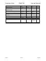
Rev N
Nov 2010
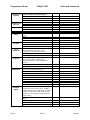
1) Pg 9 Corrected Cash Drawer Pin Assignment
Page ii
Rev N
Nov-10
Programmer’s Guide
POSjet® 1500
General Information
POSjet® 1500
Disclaimer
© 2010 TransAct Technologies, Inc. All rights reserved.
NOTICE TO ALL PERSONS RECEIVING THIS DOCUMENT:
The information in this document is subject to change without notice. No part of this document may be reproduced,
stored or transmitted in any form or by any means, electronic or mechanical, for any purpose, without the express
written permission of TransAct Technologies, Inc. ("TransAct"). This document is the property of and contains
information that is both confidential and proprietary to TransAct. Recipient shall not disclose any portion of this
document to any third party.
TRANSACT DOES NOT ASSUME ANY LIABILITY FOR DAMAGES INCURRED, DIRECTLY OR
INDIRECTLY, FROM ANY ERRORS, OMISSIONS OR DISCREPANCIES IN THE INFORMATION
CONTAINED IN THIS DOCUMENT.
Some of the product names mentioned herein are used for identification purposes only and may be trademarks
and/or registered trademarks of their respective companies.
TransAct, PowerPocket, Magnetec, Insta-Load, POSjet, Ithaca, 50Plus and "Made to Order. Built to Last" are
registered trademarks and BANKjet is a trademark of TransAct Technologies, Inc.
Copyright
© 2001 - 2010 TransAct Technologies, Inc. All rights reserved.
Revision N, November 2010
Printed in USA.
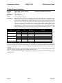
Regulatory Compliance
North America:
EMI:
Safety:
FCC Class B
UL (US)
CUL (Canada)
Europe:
CE Marking:
Safety:
Other:
CLASS B: EN55022, EN50081-1 (optional)
TUV
CB Certificate
Federal Communications Commission Radio Frequency Interference Statement
The POSjet® 1500 Printer complies with the limits for a Class A computing device in accordance with the
specifications in Part 15 of FCC rules. These regulations are designed to minimize radio frequency interference
during installation; however, there is no guarantee that radio or television interference will not occur during any
particular installation. Interference can be determined by turning the equipment off and on while the radio or
television is on. If the printer causes interference to radio or television reception, try to correct the interference by
one or more of the following measures:
Reorient the radio or television receiving antenna
Relocate the printer with respect to the receiver
Plug the printer and receiver into different circuits
If necessary, the user should consult their dealer or an experienced radio/television technician for additional
suggestions. The user may find the following booklet prepared by the Federal Communications Commission helpful:
How to Identify and Resolve Radio/TV Interference Problems. This booklet is available from the US Government
Printing Office, Washington, DC 20402. Ask for stock number 004-000-00345-4.
Nov-10
Rev N
Page iii
Programmer’s Guide
POSjet® 1500
General Information
Canadian Department of Communications Radio Interference Statement
The POSjet® 1500 Printer does not exceed Class A limits for radio noise emissions from digital apparatus set out in
the Radio Interference Regulations of the Canadian Department of Communications.
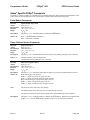
TransAct Technical Support
Monday through Friday, 8 A.M. to 8 P.M. Eastern Standard Time (excluding holidays). To obtain Technical
Support, call: TransAct at (607) 257-8901, or (877) 7-ITHACA.
Service Information
TransAct Technologies Incorporated has a full service organization to meet your printer service and repair
requirements. If your printer needs service, please contact your authorized printer service center. If any problems
still persist, you can directly contact TransAct at (607) 257-8901 or (877) 7-ITHACA for a return authorization.
International customers should contact your distributor for services. TransAct offers the following service programs
to meet your needs.
Extended Warranty
Depot Repair
Maintenance Contract
Internet Support
Please have the following information at hand:
1. The Model Number and Serial Number.
2. A list of any other peripheral devices attached to the same port as the printer.
3. The application software, operating system, and network you are using.
4. A copy of your printer‘s Configuration Settings.
5. What happened and what you were doing when the problem occurred.
6. How you tried to solve the problem.
Warranty Information
TransAct‘s POSjet® 1500 Printers come with a standard 24-month warranty that commences upon shipment from
factory, and covers parts and labor. An optional warranty, covering both parts and labor for an additional 12 months,
may be purchased separately. Repairs are warranted for 90 days from the date of repair or for the balance of the
original warranty period, which ever is greater.
Return Materials Authorization and Return Policies
If the technical support person determines that the printer should be serviced at our facility, and you want to return
the printer for repair, a Returned Materials Authorization (RMA) number must be issued before returning the
printer. Prepare the printer being returned for repair as follows:
1.
2.
3.
4.
Remove and discard ink cartridges.
Pack the printer to be returned in the original packing material. Packing items may be purchased from
TransAct's Ithaca Facility.
Return only the accessories that a Support Technician asks you to include.
Write the RMA number clearly on the outside of the box.
Shipping Printers
Never ship a printer by any means with any ink cartridge(s) installed. Be sure to save the
packing materials in the event that you need to send the printer in for servicing. TransAct Technologies is not
responsible for damaged return items that are not packaged in original shipping material.
Page iv
Rev N
Nov-10
Programmer’s Guide
POSjet® 1500
General Information
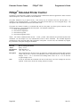
Where Can You Find More Information?
Our Internet Support and Sales Services
www.transact-tech.com
TransAct Technologies Inc. maintains an Internet web site with content devoted to product support. Within the
Support Services section you can find the most current versions of the Operator‘s Guide and Programmer‘s Guide.
1.
2.
3.
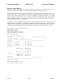
Upon entering our web site, you will be brought to the ―Welcome to TransAct‖ screen. This intro page has the
Ithaca Brand listed at the top right. Click on the Ithaca logo.
Locate and click on the Technical Support button in the green area of the ―Welcome to Ithaca‖ screen.
Use the bottom pulldown box to select the appropriate information for the printer model that you are using.
Contacting TransAct’s Ithaca Facility
Contact TransAct‘s Ithaca facility for information about the POSjet® 1500 Printer and how it works with your
system. For information on international distribution, visit our web site at www.transact-tech.com. Contact the
TransAct‘s Sales and Technical Support Departments at the following address and telephone or fax numbers.
Technical Support
Receive technical support, order documentation, request additional information, or send in a printer for service.
Sales
Order supplies, receive more product information, or order product brochures.
TransAct Technologies Incorporated
Ithaca Facility
20 Bomax Drive
Ithaca, NY 14850 USA
TransAct Technologies
World Gaming Headquarters
& Western Regional Repair Center
6700 Paradise Road
Suite D
Las Vegas, NV 89119 USA
Telephone
Main fax
Sales fax
Technical Support fax
Web site
Nov-10
(877) 7-ITHACA or (607) 257-8901
(607) 257-8922
(607) 257-3868
(607) 257-3911
http://www.transact-tech.com
Rev N
Page v
Programmer’s Guide
POSjet® 1500
General Information
Table of Contents
®
III
iii
iii
iii
iii
iii
iii
iv
iv
iv
iv
iv
iv
v
v
v
v
v
vi
xi
xiii
®
1
1
1
1
2
2
2
3
4
4
5
5
5
6
6
6
7
8
9
10
11
14
15
15
15
16
17
17
POSJET 1500
Disclaimer
Copyright
Regulatory Compliance
North America:
Europe:
Federal Communications Commission Radio Frequency Interference Statement
Canadian Department of Communications Radio Interference Statement
TransAct Technical Support
Service Information
Warranty Information
Return Materials Authorization and Return Policies
Shipping Printers
Where Can You Find More Information?
Our Internet Support and Sales Services
Contacting TransAct’s Ithaca Facility
Technical Support
Sales
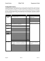
Table of Contents
Table of Tables
Table of Figures
POSJET 1500 FEATURES/SPECIFICATIONS
Standard Features
Optional Features
Additional Supported devices and tools
Drivers and Utilities Available
Optional Printer Configurations
Supported Emulations
Physical Printer Specifications
Auto-cutter (Partial Cut Option)
Sensors
Environmental Conditions
Relative Humidity
Reliability
Power and Communication Specifications
Power Requirements
Parallel Interface
RS-232 Serial Interface
USB Interface
Cash Drawer Interface Description and Specifics
Printing Specifications
Character Pitch
Graphics Generation
Media Specifications
Media Specifications
Receipt Paper (one-ply receipt)
Validation Form Requirements
Electrical Specifications
External Powered AC
Page vi
Rev N
Nov-10
Programmer’s Guide
POSjet® 1500
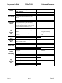
External Powered DC
Cash Drawer
17
17
SETUP AND INSTALLATION PROCEDURES
Overview of Printer Controls
Leaving the 1500 Connected to a Power Source
Operating the Keypad Controls
Button Function Descriptions:
* Button
NEW CARTRIDGE Button
FEED Button
Form Button
Open Cover Button
Indicator Light Descriptions
Unpack the Printer
Connect Power and Communications
Installation Overview
Using the Cable Restraints
Connecting the Communication Cable
Connecting the Cash Drawer
Connecting the Cash Drawer
Connecting the Power Cord (with power supply)
Connecting the DC Power Cord (no power supply)
Paper Low Setup
Adjusting the Paper-Low Sensor
Paper Low Adjustment Requirements
Loading Ink Cartridges and Paper
Installing Ink Cartridges
Installing a New Paper Roll Using Insta-Load®
Printing the Configuration Summary Receipt
Placing the Printer In Self-Test Mode (printing the Configuration Summary Receipt)
Exiting Self-Test Mode
Matching Printer Configuration Settings to your System
Verifying the Printer Setup
Verify the communications interface card
Installing the new interface card
Verify the Cash Drawer Interface
Matching the Cash Drawer Interface
®
POSJET 1500 OPERATION
Using Ink Cartridges
Care of Ink Cartridges
Determining Ink Cartridge Status
Validation Form Insertion and Orientation
Validation Orientation
Form Requirements
Inserting Validation Forms
Preventing and Clearing Validation Jams
Printer Self Testing and Diagnostics
Printer Self-Testing
Placing the Printer In Self-Test Mode
Exiting Self-Test Mode
Remote Power Down
Self-Test Hints and Suggestions
Nov-10
Table of Contents
17
18
18
18
19
19
19
19
19
20
20
21
22
22
23
24
25
26
27
28
29
29
30
31
31
33
34
34
34
34
35
35
36
36
36
38
38
38
39
40
40
40
41
42
43
43
44
44
44
44
Rev N
Page vii
Programmer’s Guide
POSjet® 1500
General Information
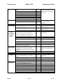
Level 0 Diagnostics
Firmware Test
Boot Loader Mode
Extended Diagnostics
Self-Test Diagnostics
Hex-dump Mode
Configuration Mode
Configuration Mode
Remote Configuration Software
Manual Configuration
Using Self-Test to View Configuration Settings
Entering Configuration Mode
Making Changes in Configuration Mode
Configurable Features
Printer Color Configuration
Ink Cartridge Setup
45
45
45
46
46
46
47
47
47
47
48
48
49
50
58
58
COLOR PRINTING AND PRINT DRIVERS
Character Graphics
APA Graphics
Color Graphics
Procedure for color horizontal graphics:
60
60
61
62
63
PRINTER DRIVERS AND PRINTER CONTROLS
General Driver Information
Installing Windows® Printer Drivers (WIN95, 98, Me)
Printer Driver Installation Instructions for NT4.0, 2000
OPOS Drivers Installation Instructions
To Install the USB drivers
Configuring Windows® Printer Drivers (WIN95, 98, Me)
Configuring Ithaca OPOS Drivers
Printer driver
Printing
General Settings
Performance
Communications Port:
Paper Out:
Cash Drawer Dialog
Printing using a printer driver (Printer Font)
Printing via a printer driver (System/Graphical/TrueType Font)
Printing via an OPOS driver
Printing via POSPrinter OCX
64
64
65
65
66
66
67
70
70
70
71
71
71
72
72
73
74
77
81
TROUBLESHOOTING
Indicator Lights (LED)
The five POSjet® 1500 indicator lights are:
Power Indicator (LED)
Error Indicator (LED)
Paper Indicator (LED)
Form Indicator (LED)
Cartridge Indicators (LED-left and right)
Fault Indicators
Three types of faults exist
Recovery from Errors
Startup Troubleshooting
82
82
82
82
82
82
82
82
82
83
83
85
Page viii
Rev N
Nov-10
Programmer’s Guide
POSjet® 1500
Table of Contents
Operational Troubleshooting
Understanding Fault Indicators
Indicator Light Blink Patterns
Keypad Indicator Troubleshooting Chart: General Problems
Keypad Indicator Troubleshooting Chart: Serious Problems
Correcting Common Operating Problems
86
86
86
87
87
88
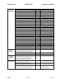
PROGRAMMING CONTROLS
Control Codes Overview
Nomenclature
Standard Emulation
IPCL Codes
EPOS Emulation
Ithaca® Microline Emulation
Application Development
Ithaca Control Codes and Commands
PcOS Printer Control Codes
Quick PcOS Reference Chart By Function
Vertical Motion
Character Pitch
Character Attributes
Electronic Journal
Quick PcOS Reference Chart (Alphabetic)
Low Level Paper Motion Control
Horizontal Motion Control
Vertical Motion Control
Character Pitch
Character Font
OCR Characters
Character Attribute Commands
Print Zone Control
Print Rotation Commands
POSjet 1500 Page Mode
POSjet® 1500 Graphics
User Store (Graphic Save)
Bar Codes
POSjet® 1500 Validation Operation
Electronic Journal
Miscellaneous Commands
Ithaca® Series 50 Compatibility Commands
ESC/POSTM Codes (EPOS)
Differences between Epson TM U325D and POSjet® 1500
Page Mode
Undocumented Epson Commands
Real-time Status
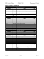
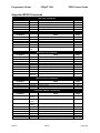
Supported TM-U325D Commands
Supported TM-U325D Commands
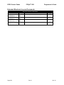
Undocumented TM-U325D Commands
Supported EPOS Commands
Supported EPOS Commands
Extended Electronic Journal Commands
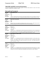
TM-U325D and EPOS Command Descriptions
90
90
90
91
91
91
91
91
92
92
93
93
93
94
96
98
102
103
105
110
113
122
123
127
128
131
140
145
152
156
162
173
189
194
194
195
195
195
196
197
198
199
201
202
203
Nov-10
Rev N
Page ix
Programmer’s Guide
POSjet® 1500
Print and Feed Commands
Line Spacing Commands
Character Commands
International Character Sets
Panel Button Commands
Paper Sensor Commands
Print Position Commands
Bit-Image Commands
Status Commands
Printing Paper Command
Page Mode
Bar Code Commands
Mechanism Control Commands
Miscellaneous Commands
Macro Function Commands
User-defined Images and Graphics Commands
Ithaca® Specific POSjet® Commands
Panel Button Commands
Paper Out/Low Sensor Commands
General Information
203
205
205
207
213
214
216
218
219
223
225
228
230
231
234
235
239
239
239
®
240
®
POSJET UNIVERSAL COLOR GRAPHICS
Print File Graphics
To generate a print file.
Store Graphics in the printer:
To Store a graphic in the printer
Print a stored graphic.
Generate a file to store graphics into a printer
How universal graphics is done
How to use IPCL commands in text strings
Load and store named graphic image
Recall and print stored named graphic image
Cautions
Universal Color Command Descriptions
POSjet® Coupon-Cut-Logo Feature
244
244
244
245
245
245
245
245
246
246
246
246
247
249
PORT PROTOCOLS AND CONNECTION SPECIFICS
Printer Flow Control and Print Buffers
Printer Buffer Size
Universal Serial Bus (USB)
USB Support and Standards
Parallel Port
Parallel Port Protocol
Parallel Port Timing
Parallel Port Inquire and IEEE 1284
Parallel Port Plug and Play
Serial Port
Serial Port Protocol
250
250
253
253
253
255
255
255
257
258
259
259
POSJET EXTENDED PRINTER CONTROL
Page x
Rev N
Nov-10
Programmer’s Guide
POSjet® 1500
Table of Contents
Print Buffer Flow
Printer Buffer Size
Serial Mode Plug and Play
Using DSR
Serial Device Identification
Serial Port Inquire
Display Pass Through
Remote Power Control
Remote Printer Reset
Reset in Serial Mode
Reset in Parallel Mode
Miscellaneous Communication Features
Power-cycle Recovery
Data Pass Through
Multi-drop Configuration
Off line Active
261
263
263
263
263
264
265
265
266
266
266
267
267
267
267
267
APPENDIX A: COMMON OPERATIONAL QUESTIONS
268
APPENDIX B: ASCII CODE TABLE
269
APPENDIX C: DEFINITION TABLE
270
APPENDIX D: ORDERING SUPPLIES
272
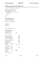
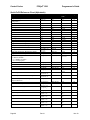
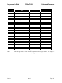
Table of Tables
Table 1 Parallel Interface Pin-outs
Table 2 Serial Interface Pin Assignments
Table 3 Cash Drawer Connectors
Table 4 Print Speed Specifications
Table 5 Character Specifications
Table 6 Possible Character Pitches
Table 7 Basic Cell Size for Draft, Large Draft, and NLQ Fonts
Table 8 Ink Cartridge Maximum Operating Conditions
Table 9 Standard Power Input Requirements
Table 10 Power Input Requirements Optional 24-volt DC Supplied from Host
Table 11 Paper Low Setup
Table 12 Carriage Configurations
Table 13 Validation: Printer Settings and Requirements
Table 14 Extended Diagnostics
Table 15 How to Change Configuration Settings
Table 16 Configurable Options
Table 17 Single Color Printer-Color Configuration Details
Table 18 Two Color Ready Operation-Color Configuration Details
Table 19 Two Color Operation-Color Configuration Details
Table 20 Color Bits Received
Table 21 StartupTroubleshooting Help
Table 22 Keypad Indicators: General Problems
Table 23 Keypad Indicators: Serious Problems
Table 24 Troubleshooting: Keypad Lights Will Not Work
Table 25 Troubleshooting: Printer Will Not Print (Error Light ON)
Table 26 Troubleshooting: Printer Will Not Print (Error Light OFF)
Table 27 Troubleshooting: Printer Prints With Missing Dots in Characters
Table 28 Troubleshooting: Printer Sounds Like It‘s Printing But Nothing Prints
Table 29 Troubleshooting: Printer Will Not Load or Feed Paper
Nov-10
Rev N
6
7
9
10
10
11
12
15
17
17
30
38
40
46
49
57
58
59
59
62
85
87
87
88
88
88
89
89
89
Page xi
Programmer’s Guide
POSjet® 1500
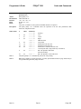
Table 30 Character Pitch
Table 31 Inter-character Spacing
Table 32 Language Table ID‘s
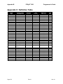
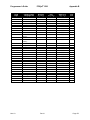
Table 33 Code Page Definition Table
Table 34 Euro Character Substitution Matrix
Table 35 OCR MA-3
Table 36 Max/Min Page Mode Height, Width, and Offsets
Table 37 Validation Form Requirements and Print Area
Table 38 Paper Sensor Commands
Table 39 Paper Sensor Commands
Table 40 Supported TM-U325D Commands
Table 41 Undocumented TM-U325D Commands
Table 42 Supported EPOS Commands
Table 43 International Character Sets
Table 44 Character Code Pages
Table 45 Character Code Table
Table 46 Print Modes
Table 47 Rotation Modes
Table 48 Paper Sensor Commands
Table 49 Paper Sensor Commands
Table 50 Print Density Selection
Table 51 Paper Sensor Status (<n> = 1, 49)
Table 52 Drawer Kick-out Connector Status (<n> = 2, 50)
Table 53 Values for the Status Function, <n>
Table 54 Printer Status (<n> = 1)
Table 55 Off line Status (<n> = 2)
Table 56 Error Status (<n> = 3)
Table 57 Paper Roll Sensor Status (<n> = 4)
Table 58 Peripheral Status (<n> = 0, 48)
Table 59 Paper Status
Table 60 Bar Code System Based on <m>
Table 61 Printing Position of HRI Characters
Table 62 Font for Human Readable Interpretation (HRI) Characters
Table 63 Printer ID
Table 64 Type ID (<n> = 2 or 50)
Table 65 Peripheral Device Bit Definitions
Table 66 Macro Control Bit Definitions
Table 67 User-defined Bit-image Resolutions
Table 68 Parallel-port Timing
Table 69 Common Operator‘s Questions (FAQ‘s)
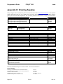
Table 70 Paper Ordering Information
Table 71 Paper Ordering Information
Table 72 Ink Cartridge Ordering Information
Table 73 Cables Ordering Information
Page xii
Rev N
General Information
111
112
115
117
118
122
132
156
175
176
197
198
199
207
209
210
211
212
214
215
218
219
220
220
220
221
221
221
222
222
228
229
229
231
231
232
234
238
256
268
272
272
272
272
Nov-10
Programmer’s Guide
POSjet® 1500
Table of Contents
Table of Figures
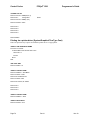
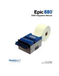
Figure 1 Printer Dimensions
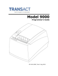
Figure 2 Receipt Printable Area
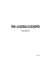
Figure 3 Environmental Conditions:Typical Operating Range
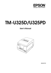
Figure 4 Cash Drawer Pin Assignments
Figure 5 Draft 12 x 12 Font
Figure 6 Large 12 x 14 Font
Figure 7 NLQ 24 x 16 Font
Figure 8 Paper Roll and Paper Core Diameters
Figure 9 Form Print Zones
Figure 10 Keypad Buttons and Indicator Lights
Figure 11 Unpacking Instructions
Figure 12 Power and Communications Connections
Figure 13 Using the Cable Restraints
Figure 14 Connecting Serial Cables
Figure 15 Connecting Parallel Cable
Figure 16 Connecting the Cash Drawer Cable
Figure 17 Connecting the AC Power Cord (with power supply)
Figure 18 Connecting the DC Power Cord (no power supply)
Figure 19 Paper Low Setup (adjusting the sensor)
Figure 21 Cash Drawer Selection
Figure 22 Cash Drawer Shunt
Figure 23 Example of Character Graphics
Figure 24 Example Commands for a Sample Receipt
Figure 25 Sample Receipt
Figure 26 Receipt with graphics
Figure 27 Page Definition
Figure 28 Page Mode entry Orientations
Figure 29 Validation Print Zone
Figure 30 Check Printing
Figure 31 Typical POS System
Figure 32 Host to Printer Link
Figure 33 Printer Communications Buffer Flow
Figure 34 Parallel-port Data Timing
Figure 35 Parallel Port ACK Timing Options
Figure 36 Serial Port Flow Control Using DTR
Figure 37 XON/XOFF Serial Port Flow Control
Nov-10
Rev N
3
4
5
9
12
12
13
15
16
18
21
22
23
24
25
26
27
28
29
36
37
60
60
61
63
131
132
157
157
250
251
252
255
256
259
260
Page xiii
Programmer’s Guide
POSjet® 1500
Features/Specifications
POSjet® 1500 Features/Specifications
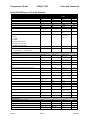
Standard Features
Print Speed: 12 lps. at 10 char. per line
Print Resolution: Max. 208 dpi. Horizontal, 96 dpi. Vertical
Simple Snap-In, No-Mess Cartridges with Fast-Drying Ink
Standard Warranty: Two Years (Extended Maintenance Plan Available)
Patented Insta-Load® Automatic Paper Loading
Cash Drawer Drivers: Dual with Status (Single RJ12)
Font Selections: Draft, Large Draft and Near Letter Quality
Selectable Printing Features of Bold, Italics, Size Scaling and Rotated
Emulations: Ithaca/IBM, Epson ESC/POS, and TM-U325, Ithaca M50, and Microline
APA and Epson Bit Map Graphics
Data Buffer: 8K (Adjustable)
208K Non-Volatile Flash for Multiple Character Sets, Bit Images and Electronic Journal
Bar Codes: Code 39, Code 93, Interleaved 2 of 5, UPC-A and UPC-E, EAN8 and EAN13, Code 128
65 Language Character Sets Supported (EURO Character Included)
Self Diagnostics
Remote Statistics
Paper Out and Ink Low Detection and Indicators
Software Developer‘s Toolkit Available
Top Drop-in Forms Insertion with Programmable Top of Form
Independent Validation
Optional Features
Auto-cutter (partial cut)
Adjustable paper low
Two-Color Printing
Universal Power Supply and PowerPocket®
Additional Supported devices and tools
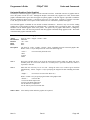
Printer Test and Configuration Programs
The POSjet® 1500 will be supported by various PC based tools. These tools include, but are not limited to the
following:
PJColor
PJColor is a program that will allow images and picture to be processed so they can work with the printer.
PJTerminal
PJTerminal is a test application that is used to verify communications to the printer.
PJBootload
PJBootload is a program that is used to replace or update the printer‘s firmware.
Ithaca Config
Ithaca Config is a program that is used to replace or update the printer‘s configuration settings.
Nov-10
Rev N
Page 1
Features/Specifications
POSjet® 1500
Programmer’s Guide
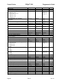
Drivers and Utilities Available
POSjet® 1500 Drivers and Utilities can be downloaded from our web site, or call our Technical Support Department
to request a Software Developer‘s Toolkit (CD-ROM).
POSjet Image Converter Utility
POSjet Image Converter (PJColor) is a tool to help develop graphic images to use as logos and coupons on the
printer. It will read and convert images to a format suitable for printing on the POSjet® 1500 printer. It will allow
you to preview the image and adjust the colors prior to printing. It will also allow the images to be stored in the
printer's User Store.
PJTerminal Utility
PJTerminal is a tool that has been developed to allow you to interactively send commands to and get responses from
the printer.
Optional Printer Configurations
Color Configuration
All POSjet® 1500 ink cartridge configurations are factory installed options.
Single Color
The single color configuration is provided with a single ink cartridge. It cannot be upgraded for two-color operation.
Two-Color Ready
The two color ready configuration is equipped with a single ink cartridge but can be easily upgraded to two-color
operation simply by installing a second ink cartridge.
Two-Color
Two-color configuration requires that two cartridges be installed in the carriage. If one of the cartridges is black, it
must be installed in the left carriage position.
Supported Emulations
Ithaca PcOS®
The Ithaca Standard emulation is the Ithaca PcOS emulation with extensions that provide full support for the
POSjet® 1500 features. This emulation is similar to the IBM control codes used in a number of IBM printers.
TM-U325
The TM-U325 emulation is intended to allow the POSjet® 1500 to replace the TM-U325 printer with no changes to
the host application.
Epson ESC/POS®
The Epson ESC/POS® emulation provides support for features in the POSjet ® 1500 printer that are not supported in
the TM-U325 emulation. POSjet® 1500 follows the Epson ESC/POS specification as close as possible.
Ithaca M50 andIthaca® Microline
The POSjet® 1500 provides M50 and M50 Microline emulations to allow older Model 50 printers to be replaced
with minimal changes to the host application.
Page 2
Rev N
Nov-10
Programmer’s Guide
POSjet® 1500
Features/Specifications
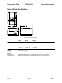
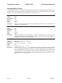
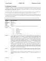
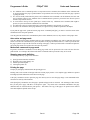
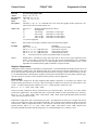
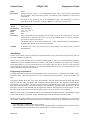
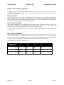
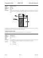
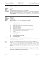
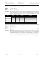
Physical Printer Specifications
Figure 1 Printer Dimensions
Width
Depth
Height
Without Knife
6.75"
(172 mm)
9.75"
(248 mm)
5.92"
(151 mm)
With Knife
6.75"
(172 mm)
9.75"
(248 mm)
6.44"
(164 mm)
Weight:
Shipping:
approx. 6 lbs. (2.7 kg)
approx. 8 lbs. (3.6 kg)
Interface
Serial RS-232C
Parallel IEEE1284
USB
Bi-directional- Ready/Busy or XON/XOFF (9-pin D-shell or 25-pin D-shell)
Bi-directional-transmit/receive/ground (25-pin D-shell or 36-pin Centronics)
Version 1.1
Nov-10
Rev N
Page 3
POSjet® 1500
Features/Specifications
Programmer’s Guide
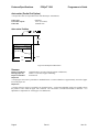
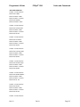
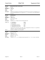
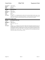
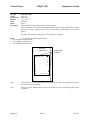
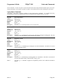
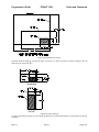
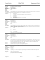
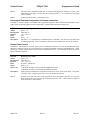
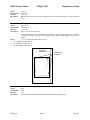
Auto-cutter (Partial Cut Option)
A receipt auto-cutter is an optional feature with all POSjet® 1500 Printers.
Cutter type
Cut to line of print
Cutter life
Guillotine
1.635" (41.52 mm)
1,000,000 cuts
Auto-cutter Position
1.635"
2.5"
0.25"
3.0"
Figure 2 Receipt Printable Area
Sensors
Paper low indicator
Receipt paper out
Paper feed method
Optional Paper Low Sensor (based on paper roll diameter).
About 1.0" (25 mm) of paper remaining
Friction feed
Paper Out
A receipt paper out sensor is provided as a standard feature. It senses when there is approximately one inch of paper
left on the paper roll.
Paper Low
A receipt paper-low sensor is provided as an optional feature. An operator-adjustable paper-low assembly allows
the printer to sense when the paper roll is between 1.42" and 0.885" (36.1mm and 22.5mm) in diameter. It is
adjustable to compensate for various paper core dimensions.
Page 4
Rev N
Nov-10
POSjet® 1500
Programmer’s Guide
Features/Specifications
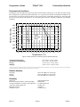
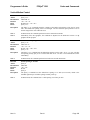
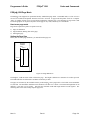
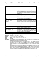
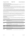
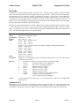
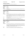
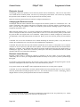
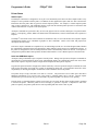
Environmental Conditions
The POSjet® 1500 is designed to be placed on point-of-sale terminals, counter tops, or any other flat, stable surface
that can support the weight of the printer (about 6 lbs. or 2.7 kg). Be aware that the environmental conditions of the
location where you place the printer will have an effect on the printer‘s performance and longevity. The printer will
run its best when stored and operated in an environment that meets the following temperature and humidity
conditions.
Storage
80%
70%
Extended Operating
Range
Relative Humidity
90%
60%
50%
40%
30%
Typical
Operating
Range
20%
10%
5%
Shipping
-40
-10
0
5
10 15 20 25 30 35 40 45
60
70
Temperature (°C)
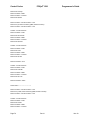
Figure 3 Environmental Conditions:Typical Operating Range
Typical Operating Range:
*Extended Operating Range:
Storage:
Shipping:
10°C to 40°C / 50°F to 104°F
0°C to 45°C / 32°F to 113°F+
-10°C to 60°C / 14°F to 140°F
-40°C to 70°C / -40°F to 158°F
* Exposure to high or low temperatures for periods of greater than 48 hours will lead to significantly reduced cartridge life. The Typical Operating Range provides full printer reliability. The
Extended Operating Range may degrade the reliability of the printer and life of the cartridge.
Relative Humidity
Operating:
Storage:
Shipping:
10% to 90% RH (non-condensing)
10% to 90% RH (non-condensing)
5% to 90% RH (non-condensing)
Reliability
Printer Life
Mean time between failures: (without cartridge):
Average cartridge life (Average 16 dots/character):
Auto-cutter option (partial cut) :
Mean time to repair:
Validation Cycles:
Nov-10
10,000,000 print lines
28,000 hours
7.0 million characters
1 million cuts
15 minutes
1 million cycles
Rev N
Page 5
POSjet® 1500
Features/Specifications
Programmer’s Guide
Power and Communication Specifications
Power Requirements
Earth Ground
+24 Vo lt Supply
Ground (+24 V dc)
DC Powered Versions
Supply voltage:
Supply Current:
24 Vdc 10%
1.0Amps
AC Powered Versions
Supply Voltage:
Frequency:
Supply Current:
100-240 Vac
50/60 Hz
.5 Amps maximum
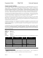
Parallel Interface
There are two parallel interface cards available. One is a 25-pin, D-shell connector. The pin-out is such that the
printer interfaces to a standard IBM PC parallel printer interface with a one-to-one cable. The second interface card
provides the same interface with a standard, 36-pin Centronics type connector. Both cards provide a dual cash
drawer interface. The tables below lists interface signals and pin definitions for both types of parallel interfaces.
25-pin D-Shell
IEEE 1284-A
36-pin Centronics
IEEE 1284-B
Parallel Pin Assignments
25-pin Connector
36-pin Connector
Signal
Description
Direction
Pin 1
Pin 1
STROBE
Clock data to printer
Host to Printer
Pins 2-9
Pins 2-9
D0 - D7
Data
Host to Printer
Pin 10
Pin 10
ACK\
Printer accepted data
Printer to Host
Pin 11
Pin 11
BUSY
Printer busy
Printer to Host
Pin 12
Pin 12
PE
Paper Out/Status
Printer to Host
Pin 13
Pin 13
SLCT
Printer selected
Printer to Host
Pin 14
Pin 14
AUTOFD
Autofeed paper
Host to Printer
Pin 15
Pin 32
FAULT\
Printer error
Printer to Host
Pin 16
Pin 31
INIT\
Initialize printer
Host to Printer
Pin 17
Pin 36
SLIN
Select printer
Host to Printer
Pin 17
FG
Frame ground
Printer to Host
-
Pin 18
+5V
Peripheral logic high
Printer to Host
Pins 18-25
Pins 16, 19-30
GND
Ground
Table 1 Parallel Interface Pin-outs
Page 6
Rev N
Nov-10
Programmer’s Guide
POSjet® 1500
Features/Specifications
Parallel Signal Voltage and Current levels
Signal Levels
Voltage levels
Logic levels
Logic one
Logic zero
Current requirements
Logic one
Logic zero
0 V and +5 V (nominal)
Driver
Receiver
Driver
Receiver
+2.4 V to +5 V
+2.0 V to +5 V
0 V to +0.4 V
0 V to +0.8 V
Source
Sink
0.25 ma at +2.4 V
16
Line termination
Data and control
Strobe
ma
3.3k ohm to +5 V
1.2k ohm to +5 V
RS-232 Serial Interface
There are two serial interface cards available. One is a 9-pin, D-shell connector. The pin-out is such that the printer
interfaces to a standard IBM PC Serial printer interface with a Serial Null Modem cable. The second interface card
provides the same interface with a standard 25-pin D-shell connector. Both interface cards provide a dual cash
drawer interface. The tables below lists interface signals and pin definitions for both types of serial interfaces.
Serial Port Features
Baud Rates
Bit Patterns
Flow Control
300, 600, 1200, 2400, 4800, 9600, 19.2K, 38.4K, and 57.6K
8-bit no parity; 8-bit odd; 8-bit even; 7-bit no parity; 7-bit odd; 7-bit even
DTR and XON/XOFF
Serial Pin Assignments
9-pin
25-pin
Signal
Description
Pin 1
Pin 8
N/C
No Connection
Pin 2
Pin 3
RX
Receive Data
Pin 3
Pin 2
TX
Transmit Data
Pin 4
Pin 20
DTR
Data Terminal Ready
Pin 5
Pin 7
GND
Signal Ground
Pin 6
Pin 6
DSR
Data Set Ready
Pin 7
Pin 4
RTS
Request to Send
Pin 8
Pin 5
CTS
Clear to Send
Pin 9
Pin 11
N/C
No Connection
Table 2 Serial Interface Pin Assignments
Nov-10
Rev N
Page 7
Features/Specifications
POSjet® 1500
Programmer’s Guide
RS-232 Serial Interface Signal Voltage and Current levels
Voltage Levels
Max
Min
+-15 Volts
+- 3 Volts
Mark = Off = -3 to –15 Volts
Space = On = +3 to +15 Volts
Because both the host and printer are DTE's (Data Terminal Equipment), they use the same serial port pin-outs. If
the cable that is used to connect the host to the printer is a pin-to-pin inter-connect, it will not work. Therefore, a
null modem or turn-around cable must be used to interconnect the host and the printer.
Display Pass Through
The display pass through feature allows a pole display to be interconnected with the printer. The printer is
connected to a host system with a special serial cable. The host sends serial data to the printer and the printer sends
serial data to the pole display. The printer does not provide power to the display. During normal printer operation,
no data is passed to the display. In pass through mode, all received data is passed on to the display.
USB Interface
The USB interface is a Version 1.1 interface that is Version 2.0 compliant. The standard USB interface card is
implemented through a Standard Series "B" Receptacle as defined in the USB Specification. The printer is selfpowered and does not draw power from the standard type B USB interface cable.
The Standard USB Type B connector has the following pin functions:
Pin Signal
1 Vbus (+5 V dc) (Not used in the POSjet® 1500)
2 Minus data
3 Plus data
4 Ground
Note: The standard USB interface does not have enough power to run the printer.
Page 8
Rev N
Nov-10
POSjet® 1500
Programmer’s Guide
Features/Specifications
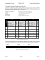
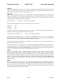
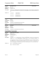
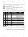
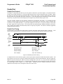
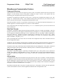
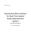
Cash Drawer Interface Description and Specifics
The POSjet® 1500 Printer supports dual cash drawers with status. The driver in the printer is capable of supplying
24 Vdc at up to 1.5 amps for 250 milliseconds. The POSjet® 1500 Printer defines cash drawer closed as switch open.
If the drawer is disconnected, the printer considers it closed. Since the printer does not act on the cash drawer status,
the application can interpret cash drawer status in a variable manner.
®
Epson (Standard)
pin 1
pin 2
pin 3
pin 4
pin 5
pin 6
Star
Signal Name
CD2CD1 Sense
Ground
CD Drive +(+24V)
CD1Not Connected
pin 1
pin 2
pin 3
pin 4
pin 5
pin 6
Not Connected
CD1CD1 Sense
CD Drive + (+24V)
CD2Ground
Signal Name
Direction
Signal Name
Direction
Pin Number
Ithaca
Single RJ12 connector with 24V sink drivers
24 volts (Refer to power supply specification)
1 amp maximum with current limit
250 msec maximum
Open/close drawer status to printer
pin 1
pin 2
pin 3
pin 4
pin 5
pin 6
Not Connected
CD1CD Drive +(+24V)
CD Drive +(+24V)
CD2CD1 Sense
1
Drawer 2 kick out drive
signal
Output
Sink
Drive
Not Connected
2
Drawer 1 open/close signal
Input
Drawer 1 kick out drive
signal
Output
Sink
Drive
Drawer 1 kick out drive
signal
3
Signal Ground
Drawer 1 open/close signal
Input
+24V DC
4
+24V DC
+24V DC
5
Drawer
signal
6
Not Connected
1
kick-out
drive
Output
Sink
Drive
Drawer 2 kick out drive
signal
Direction
Connector Type (standard)
Voltage
Current
Pulse Duration
Drawer Status
Not Connected
Output
Sink
Drive
+24V DC
Output
Sink
Drive
Signal Ground
Drawer 2 kick out drive
signal
Output
Sink
Drive
Drawer 1 open/close signal
Input
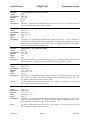
Table 3 Cash Drawer Connectors
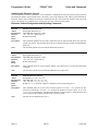
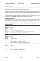
The printer can be configured for one of three cash drawer configurations. The interface card has a 14-pin header
with a 10-pin shunt installed. The shunt position defines the configuration of the cash drawer. Refer to the markings
on the board when determining where the shunt should be installed to work in the three different configurations.
Epson
Ithaca
Pin 1
Pin 1
Star
Pin 1
Figure 4 Cash Drawer Pin Assignments
Nov-10
Rev N
Page 9
POSjet® 1500
Features/Specifications
Programmer’s Guide
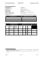
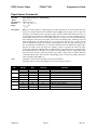
Printing Specifications
Printing method:
Cartridge arrangement:
Print dot pitch:
Printing directions:
Paper feed pitch:
Validation Type:
Number of Validation lines:
Receipt print zone (maximum):
Validation print zone:
Thermal ink jet
12 nozzle
0.0096" (0.244 mm)
Bi-directional, logic seeking
Default - 0.125" (1/8" or 3.175 mm)
Independent
Max. 9 lines (1.53") @ 6 lpi. 12 lines @ 8 lpi.
2.5" (63.5 mm)
Refer to ―Validation Form Requirements‖ on pg. 16.
Characters per Line
Minimum Lines per Second
10
12
20
10
30
8
40
6
1
Table 4 Print Speed Specifications
Print Pitch Capability
(Characters per Inch)
Font
Max Characters/Line
(2.5-inch Print Zone)
Approximate
Characters
per Second2
Half Wide
(Max CPI)
Singlewide (Max
CPI)
Doublewide
Max
Typ
Dbl-wide
Not
Available
13.0
6.5
32
32
16
100
Large
Draft
29.72
14.86
7.43
74
37
18
315
Small
Draft
29.72
17.3
8.67
74
43
21
360
NLQ
Table 5 Character Specifications
1
2
Print speed is calculated with the 12 x 12 single wide font at 17.3 cpi and 8 lpi spacing. If head maintenance
needs to be done, the print speed will be less.
The value is based on a single full 2.5" print line printing single width, small draft font. Line feed time is not
included.
Page 10
Rev N
Nov-10
Programmer’s Guide
POSjet® 1500
Features/Specifications
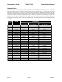
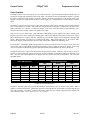
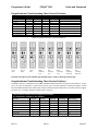
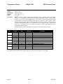
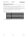
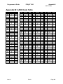
Character Pitch
Each character has at least one, half-column, inter-character spacing included within the cell size. The intercharacter spacing provides the maximum character pitch as shown in the table below. Change the spacing between
characters in one of two ways. The first is to request that right side spacing be added between characters; the other
is to request a specific pitch in characters per inch. When a specific character per inch (cpi) is selected, the printer
calculates the number of half dot columns that must be inserted or removed between characters to print at the
requested cpi. If the single width characters will overlap excessively, the printer will switch to half width characters.
It is not always possible to print at exactly the requested pitch. The printer selects the closest possible pitch to the
one chosen.
Request
ed CPI
Result
1
2
3
4
5
6
7
8
9
10
11
12
13
14
15
16
17
18
19
20
21
22
23
24
25
26
27
28
29
30
31
1.000 CPI
2.000 CPI
3.014 CPI
4.000 CPI
4.952 CPI
5.943 CPI
6.933 CPI
8.000 CPI
9.043 CPI
9.905 CPI
10.947 CPI
12.235 CPI
13.000 CPI
13.867 CPI
14.857 CPI
16.000 CPI
17.333 CPI
17.333 CPI
18.909 CPI
20.8 CPI
20.8 CPI
23.111 CPI
23.111 CPI
23.111 CPI
23.111 CPI
26.000 CPI
26.000 CPI
26.000 CPI
29.714 CPI
29.714 CPI
29.714 CPI
Nov-10
Font Format
NLQ
24 x 16 Font
Small Draft
12 x 12 Font
Std Font
Std Font
Std Font
Std Font
Std Font
Std Font
Std Font
Std Font
Std Font
Std Font
Std Font
Std Font
Std Font
Std Font
Std Font
Std Font
Not recommended
Not recommended
Not recommended
Not recommended
Not recommended
Not recommended
Not recommended
Not recommended
Not recommended
Not recommended
Not recommended
Not recommended
Not recommended
Not recommended
Not recommended
Table 6 Possible
Rev N
Std Font
Std Font
Std Font
Std Font
Std Font
Std Font
Std Font
Std Font
Std Font
Std Font
Std Font
Std Font
Std Font
Std Font
Std Font
Std Font
Std Font
Std Font
Std Font
Half Width
Half Width
Half Width
Half Width
Half Width
Half Width
Half Width
Half Width
Half Width
Half Width
Half Width
Half Width
Character Pitches
Large Draft
12 x 14 Font
Std Font
Std Font
Std Font
Std Font
Std Font
Std Font
Std Font
Std Font
Std Font
Std Font
Std Font
Std Font
Std Font
Std Font
Std Font
Std Font
Std Font
Std Font
Half Width
Half Width
Half Width
Half Width
Half Width
Half Width
Half Width
Half Width
Half Width
Half Width
Half Width
Half Width
Half Width
Page 11
Features/Specifications
POSjet® 1500
Programmer’s Guide
Standard Print
The three resident fonts in the printer are Draft, Large Draft, and Near Letter Quality (NLQ). The cell size for each
is different. In addition, the Small and Large Draft fonts can be printed in Double, Single and Half wide versions.
All width variations are based on a single width, and use mathematical algorithms to convert them to different
widths. The following discussion is based on the basic, single width character.
Character Cell
Horizontal
Vertical
Draft
12
12
Large Draft
14
12
NLQ
16
24
Table 7 Basic Cell Size for Draft, Large Draft, and NLQ Fonts
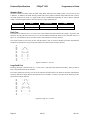
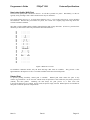
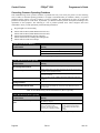
Draft Font
The draft font is defined in the 12 x 12 cell to use 6 full-columns and 5 half-columns horizontally. In general, most
characters are only nine dots wide; however, to provide readable international characters, the minimum cell size is
kept at 12. The minimum cell size provides at least 1 half-column between any character.
The vertical format never uses the top dot, and the bottom 2 dots are used for character decenders and underline.
The draft font provides the most print per line and the most efficient use of ink per character.
01
02
03
04
05
06
07
08
09
10
11
12
............
....0.0.....
...0...0....
..0.....0...
.0.......0..
.0.0.0.0.0..
.0.......0..
.0.......0..
.0.......0..
.0.......0..
............
............
Figure 5 Draft 12 x 12 Font
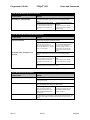
Large Draft Font
The large draft font is defined in the 12 x 14 cell to use 7 full, and 6 half-columns horizontally, which provides at
least 1 half-column between any character.
The vertical format uses the first 10 rows for the characters and the bottom 2 for character decenders and underline.
The large draft font is larger than the draft font and is more readable. It, however, provides fewer characters per line
and uses more ink per character.
01
02
03
04
05
06
07
08
09
10
11
12
.....0.0......
....0...0.....
....0...0.....
...0.....0....
..0.......0...
..0.......0...
.0.0.0.0.0.0..
.0.........0..
0...........0.
0...........0.
..............
..............
Figure 6 Large 12 x 14 Font
Page 12
Rev N
Nov-10
Programmer’s Guide
POSjet® 1500
Features/Specifications
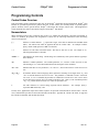
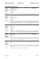
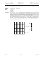
Near Letter Quality (NLQ) Font
The near letter quality font is defined in the 24 x 16 cell that is printed in 2 passes. Horizontally, 15 dots are
typically used, providing at least 1 half-column between any two characters.
The vertical format uses rows 4 - 19 for the basic character, rows 1 - 3 for accents, and rows 20 - 24 for decenders
and underlines. Because NLQ font makes two passes, the vertical size is slightly larger than large draft font.
Vertical resolution is doubled.
NLQ font is easily readable and has a higher contrast than the draft or large draft fonts. It, however, provides fewer
characters per line and uses more ink per character than either draft font.
01
02
03
04
05
06
07
08
09
10
11
12
13
14
15
16
17
18
19
20
21
22
23
24
................
................
................
.......0........
.......0........
......0.0.......
.....0...0......
.....0...0......
....0.....0.....
....0.....0.....
....0.....0.....
...0.......0....
...0.......0....
..00000000000...
..0.........0...
..0.........0...
.0...........0..
.0...........0..
0000.......0000.
................
................
................
................
................
Figure 7 NLQ 24 x 16 Font
In non-Ithaca® emulation modes, only the draft and large draft fonts are available. They provide a close
approximation to the Epson 9 x 9 and 7 x 9 formats available in the TM-U325 model printer.
Rotated Print
To provide printing flexibility, rotated print is available. Rotated print mode rotates the print in any
of three 90 orientations. In 90° and 270° rotated mode, the print data is first buffered by the printer, processed
(rotated), and then printed.
Buffering the data delays the print process as it takes some time
to process the data before it is printed. In 180° mode, the print is simply inverted. Rotated print is not available for
NLQ font or when the printer is in Epson mode.
Nov-10
Rev N
Page 13
Features/Specifications
POSjet® 1500
Programmer’s Guide
Graphics Generation
The POSjet® 1500 supports both APA graphics and color raster graphics (Horizontal graphics). In APA graphics
mode the following print resolutions are supported.
Mode
Horizontal
Vertical
Data
APA graphics
60 dpi *
96
8-bit slices
120 dpi *
96
8-bit slices
120 dpi *
192
8-bit slices
240 dpi *
192
8-bit slices
80 dpi *
96
8-bit slices
72 dpi *
96
8-bit slices
90 dpi *
96
8-bit slices
144 dpi *
96
8-bit slices
160 dpi *
96
8-bit slices
104 dpi
120
24-bit slices
208 dpi
240
24-bit slices
104 dpi
96 dpi
1 horizontal 1 vertical pass
208 dpi
96 dpi
2 horizontal 1 vertical pass
104 dpi
192 dpi
1 horizontal 2 vertical passes
208 dpi
192 dpi
2 horizontal 2 vertical passes
NOTE: Not all
resolutions are
available in all
emulations.
Horizontal graphics
* These horizontal resolutions are converted by scaling in the printer. They are printed in 104 or 208 dpi resolution.
Color graphics are supported in Horizontal graphics mode only.
Page 14
Rev N
Nov-10
POSjet® 1500
Programmer’s Guide
Features/Specifications
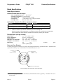
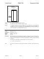
Media Specifications
Media Specifications
Hewlett-Packard Inkjet Cartridges
Print cartridge specification:
HP C6602A3
Cartridge arrangement: 12 vertical nozzles
Vertical dot pitch:
0.264 mm (0.0104") or 96dpi.
Cartridge life:
~7.0 M Characters @ 16 dots per Character.
Cartridge colors:
Black, Red, Blue, Green
Ink Cartridge Operating Conditions (maximum ratings)
Parameter
Maximum
Conditions
Shelf Life [1]
24 Months
At 73°F / 9°C in shipping package
Out of Package Life [1] (Installed in Printer)
6 Months
At 73°F / 9°C outside shipping package
Table 8 Ink Cartridge Maximum Operating Conditions
Note 1:
Total life is Shelf Life (from date of manufacture) plus Out of Package Life.
Exposure to high and low temperatures, or long exposure times near specification limits, significantly
reduce cartridge life. Higher character capacities are achieved by reducing font resolution.
Receipt Paper (one-ply receipt)
Paper width:
Paper roll diameter:
Paper thickness:
Roll paper core outside Dia.:
Roll paper core inside Dia.:
Roll footage:
3.0" ± .02" (76mm ± .5mm)
4.0" max (101.6mm max)
.003" - .004" (.07mm - .1mm)
0.82" - 0.85" (20.8 – 21.6 mm) Dia.
0.45" - 0.50" (11.4 – 12.7 mm) Dia.
330
feet
300 feet premium grade
standard
grade
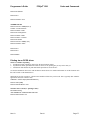
Paper and Core Diameter
To insure proper paper low detection, use paper rolls and paper that meet the specifications above. Adjustment and
operational results may vary if other thickness and width dimensions are used.
Outside Core Dia.
.82" to .85"
(20.8mm to 21.6mm)
Inside Core Dia.
.45" to .50"
(11.4mm to 12.7mm)
Refer to Paper Roll Diameter.
Figure 8 Paper Roll and Paper Core Diameters
3
Print Cartridge Specifications are controlled by Hewlett-Packard and are proprietary. Information here is for
reference only.
Nov-10
Rev N
Page 15
Features/Specifications
POSjet® 1500
Programmer’s Guide
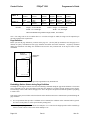
Validation Form Requirements
Form thickness-single part:
Form Size (Min):
Form Size (Max):
# Validation lines:
Check Basis weight:
.003" to .0047" (.076 mm. to .119 mm.)
2.75" high x 2.75" long (69.8 mm. x 69.8 mm.)
8.5" high x 11" long (215.9 mm. x 279.4 mm.)
9 lines @ 6lpi. 12 lines @ 8 lpi. (Max.)
24 lbs.
Figure 9 Form Print Zones
Page 16
Rev N
Nov-10
POSjet® 1500
Programmer’s Guide
Features/Specifications
Electrical Specifications
External Powered AC
The POSjet® 1500 Printer is designed to be AC self-powered in domestic and international markets. The printer is
equipped with a detachable universal input power supply that is designed to operate worldwide without
modification.
Supply Voltage
Rating (VAC)
100-240
Supply
Voltage
Range
(VAC)
90-264
Frequency
(Hz)
Rated
Power
(watts)
Idle Current
(amps)
47 - 63
25
0.08 @ 120VAC
0.04 @ 240VAC
Printing Current
(amps)
.435 @ 100 VAC
.281 @ 240 VAC
Table 9 Standard Power Input Requirements
External Powered DC
Optionally, the POSjet® 1500 Printer can be operated with an external 24-volt DC power supply.
Supply Voltage
Rating (VDC)
24-5+10%
Supply
Voltage
Range
(VDC)
22.8 -26.44
Frequency
(Hz)
DC
Power
(watts)
25W
Avg.
Idle
Current
(amps)
0.125
Current (amps)
2.0 (Cash Drawer Fire)
1.0 (Printing)
(Printing)
Table 10 Power Input Requirements Optional 24 -volt DC Supplied from Host
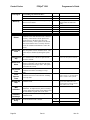
Cash Drawer
Interface Description
The POSjet® 1500 Printer supports dual cash drawers with status. The driver in the printer is capable of supplying
24 V DC at up to 1.5 amps and 250 milliseconds. The POSjet ® 1500 Printer defines cash drawer closed as switch
open. If the drawer is disconnected, the printer considers it closed. Since the printer does not act on the cash drawer
status, the application can interpret cash drawer status any way it wants.
Driver connector type (standard)
Single RJ12 connector (6 pin) with 24V sink drivers
Driver voltage
24 volts (Refer to power supply specification)
Driver current
1 amp maximum with current limit
Pulse duration
250 msec maximum
Drawer status
Open/close drawer status provided to printer
The cash drawer interface can be configured for one of three configurations. The Communications Interface card
Board has a 14-pin header with a 10-pin shunt installed on it. The shunt position defines the configuration of the
Cash Drawer. There are three settings, Ithaca®, Epson, and Star.
Setup and Installation Procedures
4
For DC powered printers, the cash drawer is supplied directly from the DC input supply. The cash drawer
requirements may effect the allowable range of voltages.
Nov-10
Rev N
Page 17
POSjet® 1500
Control Codes
Programmer's Guide
Overview of Printer Controls
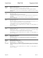
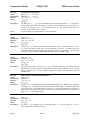
Leaving the 1500 Connected to a Power Source
The POSjet® 1500 Printer uses Hewlett-Packard inkjet print cartridges. Unlike consumer inkjet print cartridges, the
HP print cartridge does not need to be capped when not in use. Consequently, the POSjet ® 1500 is ready to print at
all times. The HP cartridge does not need to be sealed. However, the inkjet cartridge must have periodic usage to
maintain its functionality. The printer does this by cleaning the excess ink from the face of the cartridge (―wiping‖)
and firing ink into a reservoir to clean the print jets (―spitting‖). The printer performs these functions as
transparently to the host application as possible. However, the printer cannot perform these basic maintenance
procedures if the power to the printer is removed.
Do not unplug the printer from it’s power source. Instead, turn the printer to the STANDBY/OFF mode by
pressing and releasing the * Button located on the front face of the printer. Doing this prepares the ink cartridges for
periods of inactivity. Turning the printer to STANDBY/OFF maximizes the amount of time that the ink cartridge(s)
can be left without being used. When the printer is turned to STANDBY/OFF, it can sit unattended for a period of
time. To bring the printer back out of STANDBY/OFF mode, simply press the * Button. This will bring the printer
into OPERATIONAL/ON mode, which should be confirmed by the POWER INDICATOR LIGHT becoming illuminated.
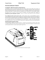
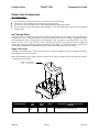
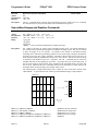
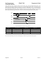
Operating the Keypad Controls
The keypad contains 3 buttons and 6 indicator lights. The * Button is used in conjunction with the keypad controls
to perform operating tasks and is located on the front of the printer. The Open Cover Button is located on the left
side of the printer console. It is used to open the printer‘s paper cover.
Figure 10 Keypad Buttons and Indicator Lights
Page 18
Rev N
Nov-10
Programmer's Guide
POSjet® 1500
Codes and Commands
Button Function Descriptions:
The primary functions of each of the buttons are described below. These buttons may also have alternate
functions when the printer is in self-test and configuration modes.
* Button
The * Button is located on the front of the printer. Since the POSjet® 1500 has been designed to remain connected to
a power source at all times, the * Button does not disconnect power to the printer, but instead switches the printer
between OPERATIONAL/ON and STANDBY/OFF modes. When the printer is in the OPERATIONAL/ON mode,
the green POWER INDICATOR LIGHT will be illuminated. None of the keypad indicator lights are illuminated when the
printer is in the STANDBY/OFF mode.
The printer will always remember the current mode that it is in when power has been disconnected and then reconnected. For example, if the printer is in STANDBY/OFF mode and the power cord is unplugged and reconnected to the printer, it will remain in STANDBY/OFF mode. If the printer is in OPERATIONAL/ON mode and
the power cord is unplugged and re-connected to the printer, it will remain in OPERATIONAL/ON mode.
NEW CARTRIDGE Button
The NEW CARTRIDGE Button works with the left and right ink cartridge indicator lights to allow an operator to
monitor and replace ink cartridges as ink levels become low. The primary functions of the NEW CARTRIDGE
Button are:
Cartridge Status Monitoring
Ink usage is monitored by the printer. When the ink supply is low, the indicator light for the left or right cartridge
will blink. After replacing the cartridge(s), press the NEW CARTRIDGE Button to inform the printer that a new
cartridge has been installed.
Note: The printer cannot distinguish between a new, full cartridge and a used cartridge. When a cartridge is
replaced, the printer will reset the ink status to full when the NEW CARTRIDGE Button is pressed. Used cartridges
should be discarded to assure that they are not re-installed into the printer
Printing Cartridge Status
Press the NEW CARTRIDGE Button to print the current status of the ink cartridges. This function is only available
when the printer is in OPERATIONAL/ON mode, with paper and cartridges installed, and covers closed. It will not
remove an ink low warning unless the cartridge has been replaced.
Printing Ink Remaining Status
Pressing the NEW CARTRIDGE Button once without changing the cartridge will print the ink status. It will not
remove the ink low warning unless the cartridge is removed and replaced while the low indication is being
displayed. If the cartridge is replaced with a used cartridge, the NEW CARTRIDGE Button should not be pressed.
FEED Button
The FEED Button is used to advance paper. If an inserted form is present in the printer, the FEED Button will move
the form in a upward direction. If no form is present, the receipt paper will be advanced.
Pressing the FEED Button momentarily will feed one line at a time. Pressing and holding the FEED Button will feed
paper continuously until it is released. The receipt paper may be fed in the reverse direction by pressing and holding
the NEW CARTRIDGE Button and the FEED Button at the same time. The reverse feed function is mostly used
while fixing a paper jam.
Form Button
The FORM Button is used for inserted form operations. Pressing the FORM Button with no form inserted in the
printer activates the automatic form loading function. The printer will flash the FORM INDICATOR LIGHT and wait for
Nov-10
Rev N
Page 19
Control Codes
POSjet® 1500
Programmer's Guide
a form to be placed in the validation slot. If a form is already present in the printer, pressing the FORM Button will
move the form in a downward direction.
Open Cover Button
The OPEN COVER Button is used to access the rear paper roll compartment and is located on the top left side of the
printer‘s outer console.
Indicator Light Descriptions
POWER INDICATOR LIGHT
ERROR INDICATOR LIGHT
PAPER INDICATOR LIGHT
FORM INDICATOR LIGHT
LEFT CARTRIDGE INDICATOR LIGHT
RIGHT CARTRIDGE INDICATOR LIGHT
Indicates printer activity and non-recoverable errors.
Indicates problems and probability of recovery.
Indicates paper status (paper low and paper out).
Indicates validation/inserted form status
Indicates ink levels of left cartridge.
Indicates ink levels of right ink cartridge.
The descriptions below reflect the normal uses of the keypad indicator lights. These indicators are also used during
self-test and errors modes to convey additional information.
Power Indicator Light (LED)
The POWER INDICATOR LIGHT becomes active when the printer is in the OPERATIONAL/ON mode.
Error Indicator Light (LED)
The ERROR INDICATOR LIGHT becomes active when a problem is detected by the printer. The ERROR INDICATOR
LIGHT,
along with the other indicators may be used to determine the cause of the problem.
Paper Indicator Light (LED)
The PAPER INDICATOR LIGHT is used to communicate the amount of paper remaining in the printer. When the paper
supply has been exhausted, the printer will stop, and the PAPER and ERROR INDICATOR LIGHTS will illuminate. When
paper is reloaded, the indicator lights will be extinguished and the printer will resume operation. If the POSjet ® 1500
is equipped with the optional paper low feature, the PAPER INDICATOR LIGHT will flash when the paper roll diameter
decreases below a preset minimum. This indication is a warning only, the printer will continue to operate normally
until the paper supply is exhausted.
Form Indicator
The FORM INDICATOR LIGHT is used during form validation operations. The FORM INDICATOR LIGHT blinks to alert
the operator that the printer is waiting for a form to be inserted/removed in the printer. The FORM INDICATOR LIGHT
will change to a steady ON condition when a form is present in the printer.
Left and Right Cartridge Indicator Lights (LED)
The printer has two ink cartridge indicator lights that display the status of the ink cartridges. The indicator light will
blink slowly when the ink level in the respective cartridge falls below a preset, programmable level. It is a warning
only, the printer will continue to operate without intervention. When ink cartridge(s) are removed, or the ink
cartridge is defective, the corresponding light will blink at a faster rate. Printer operation is inhibited until the
cartridge is replaced.
Page 20
Rev N
Nov-10
Programmer's Guide
POSjet® 1500
Codes and Commands
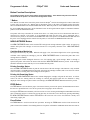
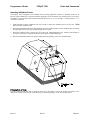
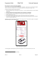
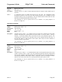
Unpack the Printer
Be sure to save the box and packing materials in case you need to send the printer in for service. TransAct
Technologies is not responsible for damaged return items that are not packaged in original shipping material. Refer
to ―Return Materials Authorization and Return Policies‖, on page iv for information on what to do if you have to
return your printer for repair.
Figure 11 Unpacking Instructions
1.
2.
3.
Open the box and remove the printer an d all items. Check to make sure that all items are present.
POSjet® 1500 Printer
Ink Cartridge(s)
Paper Roll (located under the paper cover)
PowerPocket® Power Supply: located in cabinetry base (optional)
AC Power Cord (optional)
Configuration Summary Receipt
Separate the printer from the packing material. Reverse steps when repacking for return shipment.
Check the printer for any signs of damage. If the printer or any parts are damaged, report it to your supplier and
shipper immediately.
Nov-10
Rev N
Page 21
POSjet® 1500
Control Codes
Programmer's Guide
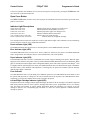
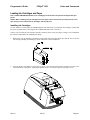
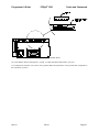
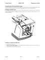
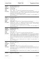
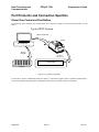
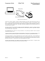
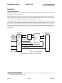
Connect Power and Communications
Installation Overview
Figure 12 Power and Communications Connections
Three cables are required to be connected to the printer
Power
Communications
Cash Drawer
Page 22
Rev N
Nov-10
POSjet® 1500
Programmer's Guide
Codes and Commands
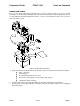
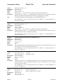
Using the Cable Restraints
Cable restraints are developed to protect against accidental unplugging of the printer while it is in use. Be sure to
properly route the communications cable using the restraints provided on the back of the printer.
Figure 13 Using the Cable Restraints
Nov-10
Rev N
Page 23
Control Codes
POSjet® 1500
Programmer's Guide
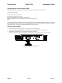
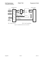
Connecting the Communication Cable
The POSjet® 1500 may be equipped with a number of different communications interface cards.
These interfaces include:
RS-232 Serial with 9-pin connector
RS-232 Serial with 25-pin connector
IEEE1284 Parallel with 25-pin connector (IEEE1284-A)
IEEE1284 Parallel with 36-pin Centronics style connector (IEEE1284-B)
USB
Connect the appropriate communications cable to the printer as shown in the following figures. Cables are provided
by your dealer, the system installer or are available through TransAct. If you are unsure of the interface installed in
your printer, refer to ―Verify the communications interface card‖ on page 35.
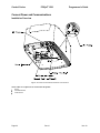
Connecting Serial Cables
1.
2.
3.
4.
Disconnect all power from the printer and host system or personal computer.
Connect the 9/25-pin Serial Interface Cable to the connector located on the back of the printer.
Tighten the two mounting screws on each side of the cable connector.
Route the Communication Cable through the Cable Restraint and connect the cable to your host system.
Figure 14 Connecting Serial Cables
Page 24
Rev N
Nov-10
Programmer's Guide
POSjet® 1500
Codes and Commands
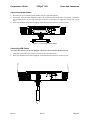
Connecting Parallel Cables
1.
2.
3.
Disconnect all power from the printer and host system or personal computer.
Connect the 25/36-pin Parallel Interface Cable to the connector located on the back of the printer. Tighten the
two mounting screws on each side of the cable connector (25-pin only). Or, engage the locking clips (36-pin
only).
Route the Communication Cable through the Cable Restraint and connect to your host system.
Figure 15 Connecting Parallel Cable
Connecting USB Cables
Note: the USB connector can be “hot plugged”. The power does not need to be disconnected.
1.
2.
Connect the USB cable to the connector located on the back of the printer.
Route the Communication Cable through the Cable Restraint and connect to your host system.
Nov-10
Rev N
Page 25
POSjet® 1500
Control Codes
Programmer's Guide
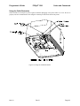
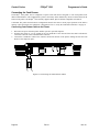
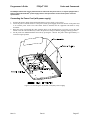
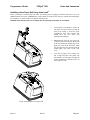
Connecting the Cash Drawer
The POSjet® 1500 printer can be configured to operate with cash drawers designed to work with printers from
different manufacturers. This configuration is preset at the factory and is identified by means of a label affixed to the
bottom of the printer. The POSjet® 1500 currently supports Ithaca, Epson, and Star compatible cash drawers.
CAUTION: The printer and cash drawer configurations must be the same to ensure proper operation. If the label is
missing or does not match your cash drawer configuration, refer to ―Verify the Cash Drawer Interface‖ on page 36.
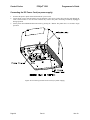
Connecting Cash Drawer Cable to the Printer
1.
2.
3.
Disconnect all power from the printer and host system or personal computer.
Orientate the printer so you are looking at the rear underside of the unit and locate the small Cash Drawer
Connector to the left of the Communication Connector.
Connect the Cash Drawer Cable to the connector located on the back of the printer, making sure that the Cash
Drawer Cable snaps into place.
Figure 16 Connecting the Cash Drawer Cable
Page 26
Rev N
Nov-10
Programmer's Guide
POSjet® 1500
Codes and Commands
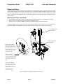
®
The POSjet 1500 Printer may be powered from an external 24 Vdc power source, or may be equipped with a
®
factory installed PowerPocket power supply. Refer to the specification section for DC power connector
specifications.
Connecting the Power Cord (with power supply)
1.
2.
3.
4.
Orientate the printer upside-down and find the POSjet‘s power supply‘s power socket.
Locate the power cord and connect it to the power socket (power supply) located on the back of the printer and
to an external power outlet. The socket-outlet shall be installed near the equipment and shall be easily
accessible.
Route the power cord through the cable restraints. Refer to the drawing below to see how to route the cord.
Failure to use the cable restraints may result in the printer becoming accidentally unplugged during operation.
Set the printer into OPERATIONAL/ON mode by pressing the * Button. The printer takes approximately 1.5
seconds to begin operation.
Figure 17 Connecting the AC Power Cord (with power s upply)
Nov-10
Rev N
Page 27
Control Codes
POSjet® 1500
Programmer's Guide
Connecting the DC Power Cord (no power supply)
1.
2.
3.
Orientate the printer upside-down and find the DC power socket.
Locate the DC power cord and connect it to the Interface Card‘s power socket, then route the cord through the
cable restraint. Failure to use the cable restraints may result in the printer becoming accidentally unplugged
during operation.
Set the printer into OPERATIONAL/ON mode by pressing the * Button. The printer takes 1.5 seconds to begin
operation.
Figure 18 Connecting the DC Power Cord (no power supply)
Page 28
Rev N
Nov-10
Programmer's Guide
POSjet® 1500
Codes and Commands
Paper Low Setup
A receipt paper-low sensor is provided as an optional feature. This adjustable paper-low assembly allows the printer
to detect when the paper roll is between 1.42" and 0.885" (36.1mm and 22.4mm) in diameter, and to issue a paper
low status to the application. All printers are shipped with a mid-position setting, that can be adjusted up or down,
with 1 to 3 full turns of the adjustment screw. In general, the paper low setup does not need to be changed from the
factory setting.
Adjusting the Paper-Low Sensor
1.
2.
3.
Use the Open Cover Button to release the rear paper cover and locate the paper low adjustment access hole.
Refer to Table 2 on the following page for specific adjustment settings.
Turn the screw to control the amount of paper that is remaining after paper low has occurred.
CAUTION: When the sensor touches the plastic of the Cabinetry Base (lower limit only), the sensor should not be
adjusted any further. Over adjustment will cause stress in the sensor material and will decrease its longevity.
#1 Phillips head
screw driver
Paper adjustment
access hole
Upper Limit Setting:
When adjusted, the sensor
will move up and away from
the Cabinetry Base. Do not
adjust anymore than 3 turns
counter clockwise from the
mid-position setting.
Factory Setting:
The factory setting leaves
room for adjusting the Paper
Low Sensor up or down by
three full turns with a screw
driver.
Lower Limit Setting:
When adjusted, the sensor
moves down and toward the
Cabinetry Base. Do not
adjust anymore than 3 turns
clockwise, from the
mid-position setting.
Figure 19 Paper Low Setup (adjusting the sensor)
Nov-10
Rev N
Page 29
Control Codes
POSjet® 1500
Programmer's Guide
Paper Low Adjustment Requirements
Use the following table to decide how much paper you want to remain after paper low sensing has occurred.
TransAct‘s expected results are based on paper and paper roll with these specifications. Refer to ―Paper and Core
Diameter‖ on page 15 for paper measurements.
Paper Low Adjustment Settings
Approximate Paper
Remaining (in feet)
Paper Roll Diameter
UPPER LIMIT: 3 turns (counter clockwise)
24'
1.420" (36mm)
2 turns (counter clockwise)
22'
1.375" (34.9mm)
1 turns (counter clockwise)
16‟
1.250" (31.7mm)
FACTORY SETTING
12'
1.175" (29.8mm)
1 turn (clockwise)
7'
1.050" (26.6mm)
2 turns (clockwise)
3.5'
.950" (24.1mm)
LOWER LIMIT: 3 turns (clockwise)
1.25'
.885" (22.4mm)
Table 11 Paper Low Setup
Page 30
Rev N
Nov-10
Programmer's Guide
POSjet® 1500
Codes and Commands
Loading Ink Cartridges and Paper
Note 1: FIRST TIME INSTALLATION: An ink cartridge(s) can be found in the pouch that shipped with your
printer.
NOTE 2: When installing new ink cartridges and a new paper roll for the first time, you may leave the cover
open until you have installed the ink cartridges, and the paper roll.
Installing Ink Cartridges
Use the * Button to set the printer into OPERATIONAL/ON mode before you install the ink cartridges. Confirm that
the printer is in this mode by checking that the POWER INDICATOR LIGHT is activated.
Caution: Do not touch the ink cartridge‘s metallic connector surface with your fingers. Doing so will contaminate
the connector and produce sub-standard print quality.
1.
Remove the new ink cartridge(s) from their sealed pouch and remove the Mylar tape from the face of the new
ink cartridge. (Holding the cartridge by the tab will ensure a clean installation.)
2.
Press the Open Cover Button to release the rear paper cover from the console, then swing the rear paper cover
towards the back of the printer. (Opening the printer‘s front cover will also open the rear paper cover.)
Nov-10
Rev N
Page 31
Control Codes
POSjet® 1500
Programmer's Guide
NOTE: If paper is present, ensure that the receipt is torn off prior to opening the front cover.
3.
4.
Pull down the blue cartridge latch/latches (1) and remove the old ink cartridges (2).
Place the new ink cartridge(s) into the carriage (3). Hold the cartridges by their tab to ensure a clean installation.
(Install the cartridge so that the tab is facing the front of the printer.) Close blue latch/latches (4).
5.
Close all of the printer‘s covers and press the NEW CARTRIDGE Button. Doing this initializes the ink status on
the newly inserted ink cartridges.
NOTE: If you experience any problems, refer to ―Printer Color Configuration‖ on page 58 to confirm that your
printer has the proper configuration settings.
Page 32
Rev N
Nov-10
Programmer's Guide
POSjet® 1500
Codes and Commands
Installing a New Paper Roll Using Insta-Load®
Before you attempt to load the paper roll, make sure that the printer is plugged in and that the printer is set to the
OPERATIONAL/ON mode. !IMPORTANT!: Paper cannot be loaded for the first time without first installing the
ink cartridge(s). A small receipt roll is supplied with the printer.
ALWAYS check that the paper core is aligned with the right edge of the paper roll as installed.
1.
Use the Open Cover Button to release the
rear paper cover; then swing it towards the
back of the printer to reveal the paper
compartment. (First time installers will
already have the cover open from
installing ink cartridges.)
2.
IMPORTANT! Insert the new paper roll
so that the paper unwinds from the bottom
of the roll, and that the leading edge of the
paper rests on top of the front cover. Make
sure the paper does not extend beyond the
molded paper stop mark on the front
cover.
3.
Close the rear paper cover; making sure
that it snaps into place. The printer will
automatically load the paper through the
feeding mechanism. If the paper does not
feed, repeat the steps.
Figure 20 Installing the New Paper Roll
Nov-10
Rev N
Page 33
Control Codes
POSjet® 1500
Programmer's Guide
Printing the Configuration Summary Receipt
This printer has been shipped with a pre-printed, Configuration Summary Receipt that shows how the printer has
been configured at our factory. This Configuration Summary Receipt can be found in the paper compartment of your
printer. Save this receipt for future reference. In the event that you need to view your printer‘s configuration settings,
but do not have your Configuration Summary Receipt, you can print a new one using the printer‘s self-test mode.
Use the configuration summary receipt to compare printer configuration settings to your system requirements.
Specific attention should be given to ensure that the emulation and the communications link are properly configured.
If they do not match the settings of your system, the printer may appear inoperative.
Follow the steps below to print a new Configuration Summary Receipt:
Placing the Printer In Self-Test Mode (printing the Configuration Summary
Receipt)
The NEW CARTRIDGE Button is used to enter the POSjet‘s self-test mode. To place the POSjet® in self-test mode,
first be sure that a paper roll is loaded and that the POWER INDICATOR LIGHT is off.
1.
If the POWER INDICATOR LIGHT is illuminated, press and release the * Button to turn the printer into
STANDBY/OFF mode.
2.
Press and hold the NEW CARTRIDGE Button.
3.
While holding the NEW CARTRIDGE Button, press and release the * Button.
4.
5.
When the red, ERROR INDICATOR LIGHT blinks, release the NEW CARTRIDGE Button.
You are now in self-test mode. Read the directions on top of the printed receipt to cycle through the menu
options.
Select the ―TEST-PRINT CONFIGURATION‖ menu option.
6.
Exiting Self-Test Mode
Exit Self-Test mode at anytime by pressing the * Button to place the printer back into OPERATIONAL/ON mode.
At this point, your printer should be completely installed and ready to accept commands. Refer to our on-line
Operator’s Guide for additional information about setup troubleshooting, printer specifications, and
operational information.
Matching Printer Configuration Settings to your System
If you are experiencing inconsistent printing operation, or if the printer appears to be non-responsive, several of the
printer configuration settings need to be set to match the requirements of your system.
Parallel Printer
Emulation
Carriage Return Options
Serial Printer
Emulation
RS-232 Serial Interface (baud rate)
Carriage Return Options
TransAct recommends that ONLY THE ABOVE SETTINGS BE ALTERED and does not recommend that these
re-configurations be made by anybody but a trained service technician who has successfully completed
®
training on the POSjet 1500. Please remember that these settings are only a few of the possible configurable
options. If you continue to experience incompatibility issues after changing these settings to match your
system, contact TransAct’s Technical Support Department for assistance.
Page 34
Rev N
Nov-10
Programmer's Guide
POSjet® 1500
Codes and Commands
Verifying the Printer Setup
Before you install a POSjet® 1500 Printer into your system, you should verify that the printer is configured as
required by your system. There are four parts to this verification process.
1.
2.
3.
4.
Verify that the communications interface card is the correct one.
Verify that the cash drawer interface is configured correctly
Verify that the power connection is correct.
Verify that the firmware in the printer is configured correctly.
Verify the communications interface card
There are three basic types of interface cards and each has variations. Make sure your printer has the correct
interface card.
Parallel Interface
Centronics 36-pin interface
25-pin D shell
Serial Interface
9-pin D shell interface
25-pin D shell interface
USB Interface
Standard 4-pin
The POSjet® 1500 Printer can be installed to use either a 25-pin Serial and 25-pin Parallel interface card. To
determine what interface is installed refer to the configuration receipt shipped with the printer, or enter configuration
mode and look at the verification print out. If a serial interface card is installed, the print out will refer to the RS232 serial interface. If the parallel interface card is installed, the print out will refer to the Parallel interface.
Changing Interface Cards
The interface card on the POSjet® 1500 Printer can be changed in the field.
In most cases, interface cards are interchangeable without altering the printer firmware. However, you may have to
load new firmware and/or boot loader before you change the interface cards. Check with Technical Support for
firmware compatibility between interface cards before ordering.
Removing the Old Interface Card
1.
2.
3.
4.
5.
6.
Turn over the printer. Take care not to allow the cover to open or the paper to fall.
Disconnect the current communications and cash drawer cables.
If equipped, unsnap the power supply retainer and slide out the power supply.
Disconnect the power supply from the interface card.
Remove the interface retaining screw.
Slide the interface card sideways-towards the power supply pocket-and remove it.
MAKE SURE the cash drawer is configured correctly. (See the next page)
Nov-10
Rev N
Page 35
Control Codes
POSjet® 1500
Programmer's Guide
Installing the new interface card
Configure the cash drawer jumpers. See "Verify the Cash Drawer Interface‖ on page 36.
1. Slide the interface card into the printer. Make sure the interface card sits flush with the retaining screw
mounting bracket. The retaining screw should also line up with the hole in the new interface card.
2.
Install the retaining screw.
3.
Reconnect the power supply to the new interface card.
4.
Reinstall the power supply into the PowerPocket® and reattach the retainer.
5.
Connect the communications interface card, and the cash drawer‘s cables.
6.
Turn over the printer, and reconnect the power.
Verify the Cash Drawer Interface
The printer is shipped from the factory with a cash drawer interface label on the bottom of the printer. You should
always verify that the cash drawer you are using matches the printer‘s cash drawer interface label. If there is no
cash drawer label, you should remove the communications interface card and verify the setting.
There are many vendors of cash drawers. If you are unsure what the cash drawer interface is, contact the cash
drawer vendor for more information.
If you find that the cash drawer does not match the printer, you may change the printer's cash drawer interface
configuration as shown on page 17. If the cash drawer interface no longer matches the label on the printer, please
remove the label.
Matching the Cash Drawer Interface
Epson
Ithaca
Pin 1
Pin 1
Star
Pin 1
Figure 21 Cash Drawer Selection
The cash drawer shunt setting is printed on the communications interface card. When you change the
communications interface card, it is very important that the cash drawer configuration of the new interface card
matches your cash drawer.
Page 36
Rev N
Nov-10
Programmer's Guide
POSjet® 1500
Codes and Commands
Figure 22 Cash Drawer Shunt
See ―Cash Drawer interface descriptions‖, on page 17 to help determine what interface you need.
To reconfigure the interface card, remove the 5-position shunt and reposition it to the position that corresponds to
the cash drawer you have.
Nov-10
Rev N
Page 37
POSjet® 1500
Control Codes
Programmer's Guide
POSjet® 1500 Operation
Using Ink Cartridges
The POSjet® 1500 is available in single or dual cartridge configurations. Several physical differences exist between
the single and dual cartridge printers. The most obvious is the ability to install two ink cartridges in a dual cartridge
printer. The second and less obvious is the dual wiper in a dual cartridge printer. For the printer to operate
correctly, the firmware needs to know the number of installed ink cartridges, and the color of both cartridges.
Carriage Configuration
Left Pen
Single
Dual (Color Ready)
Dual
Dual
Dual
Dual
Black
Black
Black
Black
Black
Black
Right Pen
Not Used
Not Used
Red
Green
Blue
Custom
Table 12 Carriage
Wiper
Configurations
Fixed
Black Only
Dual
Black - None
Dual
Black - Red
Dual
Black - Green
Dual
Black - Blue
Dual
Black - Red, Green, or Blue5
Configurations
It is not possible to configure the printer to operate with two black cartridges. If a second black cartridge is
installed, the printer will not maintain it, and the cartridge will dry out and become unusable. Do not store a spare
cartridge in the second position. Once the seal is broken, the cartridge will be exposed to the air, and should be
placed in an operational printer.
Care of Ink Cartridges
Ink cartridges should be stored in the sealed HP packaging. Once a print cartridge is unsealed, it should be placed in
an operating printer. If a printer is taken out of service, the print cartridge should be removed and discarded. Never
ship a printer by any means with a print cartridge installed. The pressure variations can cause the cartridge to
become unprimed and/or purge. If you are going to ship a printer, remove and discard the print cartridge or
cartridges.
5
Custom second colors, when available, should select the closest primary color.
Page 38
Rev N
Nov-10
Programmer's Guide
POSjet® 1500
Codes and Commands
Determining Ink Cartridge Status
The POSjet® 1500 has been designed to monitor ink consumption rates and report ink levels to the user via a
printable ink status. To print out an ink status receipt press the NEW CARTRIDGE button.
Re-using cartridges will negate the printer‘s ability to monitor ink consumption rates effectively. If the NEW
CARTRIDGE button is pressed with a newly inserted used cartridge in place, the printer will reset the ink level
counter. Due to undetermined ink levels used cartridge, the printer‘s counter will not be able to define the amount
that the cartridge is actually holding. TransAct does not recommend replacing a used cartridge with anything but a
new ink cartridge that is approved and compatible with the printer. TransAct recommends that used cartridges be
discarded after they are removed from the printer.
Refer to the following information as a guide for determining when ink cartridges need replacing.
Keypad Status
Indicator Light (LED)
Status and Sequence
Right Cartridge Low
Power LED
ON
Error LED
OFF
Paper LED
OFF
Left Cartridge LED
OFF
Right Cartridge LED
1 BLINK
Power LED
ON
Error LED
OFF
Paper LED
OFF
Left Cartridge LED
1 BLINK
Right Cartridge LED
OFF
Low Power LED
ON
Error LED
OFF
Paper LED
OFF
Left Cartridge LED
1 BLINK
Right Cartridge LED
1 BLINK
Power LED
ON
Error LED
ON
Paper LED
OFF
Left Cartridge LED
OFF
Right Cartridge LED
ON
Power LED
ON
Error LED
ON
Paper LED
OFF
Left Cartridge LED
ON
Right Cartridge LED
OFF
Left Cartridge Low
Both Cartridges
Right Cartridge Removed
Left Cartridge Removed
Nov-10
Rev N
Page 39
POSjet® 1500
Control Codes
Programmer's Guide
Validation Form Insertion and Orientation
Validation Orientation
The POSjet® 1500 accepts validation forms in both portrait and landscape orientations. Each of the two different
orientations have specific print zones, and print character spacing requirements. Regardless of the insertion
orientation, the minimum and maximum media size that can be accepted by the printer are as follows:
Form Requirements
Landscape Mode
Form size (Min.):
Form Size (Max):
Maximum Print Area:
2.75‖ width x 2.75‖ height (69.8 mm x 69.8 mm).
8.5‖ width x 11‖ height (215.9 mm x 279.4 mm).
2.5‖ width x 1.5‖ height
Portrait Mode
Form size (Min.):
Form Size (Max):
Maximum Print Area:
2.75‖ width x 2.75‖ height (69.8 mm x 69.8 mm).
2.75‖ width x 8.75‖ height (69.8 mm x 222.3 mm).
2.5‖ width x 7.8‖ height
In addition to the Min/Max size requirements, it is very important to use paper having a thickness between .003" to
.0047" (.076 mm. to .119 mm.). Using paper that is thicker than this may cause printing inconsistencies, and /or
paper jams. Refer to ―Validation Form Requirements‖ on page 16 for a complete listing of specifications regarding
the use of validation forms.
Printer Settings
Form Orientation
Portrait (vertical)
Character Line Spacing
10 character lines per inch
Number of printed character lines
51 ( on 6 inch form)
Portrait (vertical)
10 character lines per inch
78 (on 8.75 inch form)
Landscape (horizontal)
8 character lines per inch
Months
9
Landscape (horizontal)
At
°C
8 character lines per inch
12 23°C outside shipping package
Table 13 Validation: Printer Settings and Requirements
48
Hours [2]
Meters
In sealed container
Page 40
Rev N
Nov-10
Programmer's Guide
POSjet® 1500
Codes and Commands
Inserting Validation Forms
The POSjet® 1500 is designed to run validation either by using application software, or manually. Forms can be
inserted in either landscape or portrait orientation. Regardless of the orientation, the insertion process is the same.
The POSjet® 1500 can accept forms with measurements between 2.75" x 2.75" (69.8mm x 69.8mm) and 8.5" x 11"
(215.9mm x 279.4mm).
1.
Send appropriate control commands from your system to initiate the validation process or press the FORM
Button to enter validation mode.
2.
When the FORM INDICATOR LIGHT starts blinking, insert the validation paper into the validation paper inlet using
the right edge (form stop) of the validation paper inlet as a guide.
3.
When the validation sheet is detected by the sensors, the FORM INDICATOR LIGHT changes from blinking to
steady ON. The paper is automatically drawn into the printer, and printing begins.
4.
When the FORM INDICATOR LIGHT begins to blink again after printing, remove the validation paper.
Printable Side of Form
The side of the inserted form that is facing the front end of the printer is where the printing will always occur.
Always insert forms so that the side of the form that you want the printing to occur on is facing forward.
Nov-10
Rev N
Page 41
Control Codes
POSjet® 1500
Programmer's Guide
Preventing and Clearing Validation Jams
Inserted forms should not be touched during the printing, or ejection process. Pressing or pulling the paper during
ejection may cause the validation process to jam. If a jam condition occurs, clear it as described below:
Removing a Validation Jam
If a validation jam occurs, and the top of the form is still visible in the form insertion area, remove the form by
simply pressing and holding the FEED Button. If the top of the form is not visible in the form insertion area, it can
be removed manually.
Removing a Validation Jam Manually
1.
2.
3.
Open the printer‘s front cover.
Insert your index finger underneath the ink carriage and evenly pull the form out toward you until it is
completely removed from the printer.
Close the printer‘s covers and resume operation.
Page 42
Rev N
Nov-10
Programmer's Guide
POSjet® 1500
Codes and Commands
Printer Self Testing and Diagnostics
Printer Self-Testing
The POSjet® 1500 has been designed to perform several self-tests and will also allow a technician to access the
printer‘s configuration settings. It is important to insure that the printer will perform a self-test. This isolates printing
problems to something other than the operation of the printer itself. The POSjet ® has a total of ten self-test options
with four designed to be useful when performing on-site evaluations. These four tests are the only options that
should be used to test your printer. The other six testing options are used for printer demonstrations and factory
setup by TransAct. Use the following four test options when trying to correct a printing problem.
®
Use the following testing options when beginning to troubleshoot and repair the POSjet 1500.
TEST-Receipt
The receipt test is the primary test option to use when determining if the printer is functioning correctly. The receipt
test is mostly used during the early stages of troubleshooting to eliminate the possibility that the problem is
occurring with the printer. If the printer experiences a failure, and the ERROR INDICATOR LIGHT is activated, call
TransAct‘s Ithaca Facility‘s Technical Support Department.
TEST-Print Configuration
The print configuration test is a quick and easy way for you to see how your printer has been configured at the
factory without actually having to enter into configuration mode. A large percentage of initial installation and setup
problems can be attributed to the printer‘s configuration not matching the user‘s system settings. Using this test will
show you the current configuration settings of the printer.
TEST-Validation
Validation test will validate the back of a check or inserted form. Nine lines of validation information will be
printed.
TEST-Check Test
Check test will perform the check insertion process and print a sample check test.
Disregard the following options when cycling through the menu:
The following six self-test options are only extended functionality tests and do not need to be run in order to
determine if the printer is running properly. These test options are only used for printer demonstrations and factory
setup.
TEST-Graphics
TEST-Print Specs
TEST-Validation
TEST-Check
TEST-Pyramid
TEST-Burn in
TEST-Bar Codes
TEST-Rolling ASCI
Nov-10
Rev N
Page 43
Control Codes
POSjet® 1500
Programmer's Guide
Placing the Printer In Self-Test Mode
The NEW CARTRIDGE Button may be used to enter the POSjet‘s self-test mode. To place the POSjet® in self-test
mode, be sure that a paper roll is loaded. The POWER INDICATOR LIGHT should not be illuminated when trying to
place the printer in self-test mode.
1.
Press and release the * Button to switch the printer into STANDBY/OFF mode. (The POWER INDICATOR LIGHT
will be not be illuminated.)
2.
Press and hold the NEW CARTRIDGE Button.
3.
While holding the NEW CARTRIDGE Button, press and release the * Button.
4.
5.
When the red, ERROR INDICATOR LIGHT blinks, release the NEW CARTRIDGE Button.
Follow the directions printed on the receipt to cycle through and select the desired TEST option.
Exiting Self-Test Mode
Exit Self-Test mode at anytime by pressing the * Button to place the printer back into OPERATIONAL/ON mode.
Remote Power Down
The POSjet® 1500 has a command that instructs it to turn the printer into STANDBY/OFF mode. When the
command is issued, the printer performs print cartridge maintenance and enters STANDBY/OFF. Unlike pushing
the * Button, remote power down mode leaves the communications active. All commands except the exit power
down command are ignored.
If the * Button is pressed after the power down command is issued, the printer will reactivate. If power is lost after
the power down command is issued, the printer will remember it is in STANDBY/OFF mode, but will not reactivate
the communications link. The * Button must be pressed to restart the printer.
Self-Test Hints and Suggestions
If the printer fails to complete or enter into self-test mode, disconnect it from the application system.
Contact TransAct‘s Ithaca Facility‘s Technical Support Department if self-test mode fails in any way.
Page 44
Rev N
Nov-10
Programmer's Guide
POSjet® 1500
Codes and Commands
Level 0 Diagnostics
Level 0 diagnostics always and only run at power up.
Level 0 diagnostics perform the following tasks:
1.
2.
3.
4.
5.
6.
7.
8.
9.
10.
11.
Basic System Integrity
Vector Integrity
RAM Test
Flash Boot Loader Integrity
Flash Firmware Integrity
Start Normal Firmware
Verify Configuration Integrity
Interface Card Configuration
User-store Integrity
Electronic Journal Integrity (and repair if necessary)
Start Kernel, Verify Multitasking, Start Tasks
12.
13.
14.
15.
16.
17.
18.
19.
Once the kernel is running, the following tests must pass to allow operation.
However, if any test fails (except the knife home test), the remaining tests
will generate recoverable faults and normal operation will start as soon as the
fault is cleared. These tests are also run when operation is resumed from
OFF.
Cartridge Integrity
Cover Closed Check
Knife Home (if installed)
Carriage Home
Schedule Cartridge Maintenance
Paper Present
Assure the validation path is clear.
Place Printer On-line, Start Normal Operation
Firmware Test
The flash test has two phases. The first phase determines that the boot loader is accurate, and the second verifies
that the printer firmware is correct. All tests, up to and including the boot loader test, generate non-recoverable
errors when they fail. The power must be removed from the printer, and the printer must be returned for service.
If the boot loader is intact, but the main firmware is bad, the printer automatically enters boot loader mode. The
firmware will re-loaded into the printer.
Boot Loader Mode
The boot loader cannot be entered during normal operation. Boot loader mode can only be entered in one of two
ways. One, when Level 0 Diagnostics finds that the firmware check CRC is bad, or two, manually. To manually
enter the boot loader, hold the * Button during power up. The ERROR indicator comes on, and the POWER indicator
blinks. At this time, the firmware boot file may be sent to the printer. Level 0 diagnostics are prevented from
starting the firmware and boot load mode is forced to begin.
Nov-10
Rev N
Page 45
POSjet® 1500
Control Codes
Programmer's Guide
Extended Diagnostics
Extended diagnostics are entered after Level 0 diagnostics, are part of the firmware, and are activated in one of two
ways. The first is by holding NEW CARTRIDGE button E and/or FEED button and applying power (Power On).
The second is by holding NEW CARTRIDGE button and/or FEED button and activating the * Button from OFF or
Soft Power On.
OFF
NEW
CARTRIDGE
Off
On
Off
On
Off
On
Off
On
Power On
Power On
Power On
Power On
Soft Power On
Soft Power On
Soft Power On
Soft Power On
FEED
Off
Off
On
On
Off
Off
On
On
TEST
Normal Operation
Self Test Diagnostics
Manual Configuration
Manual Emulation Set
Normal Operation
Color Alignment
Hex-dump Print
Not Defined
Configuration
Table 14 Extended Diagnostics
Self-Test Diagnostics
Self-test mode allows the printer to be tested to assure that it is working correctly. A number of tests may be run.
Self-test is entered by holding the NEW CARTRIDGE button during initial power on.
Hex-dump Mode
To enter hex-dump mode, press and hold the FEED button when resuming operation from OFF mode. Enter OFF by
pressing and releasing the * Button. Press and hold the FEED button while pressing and releasing the * Button. Be
sure to release the FEED button as soon as the carriage starts to move to prevent paper feeds.
Hex-dump mode is used to diagnose communication problems with the printer. As information is received by the
printer, the information is converted to a Hex/ASCII format and printed. No translation is made, which means no
commands are interpreted. All information is converted to Hex/ASCII and printed on the receipt. If a carriage
return is sent to the printer, it is translated to 0D in the hexadecimal field and "." in the ASCII field.
The format follows.
54
61
68
20
69
74
73
65
20
73
69
74
73
0D
20
0A
This is
a test..
Several indications of printer and host communication problems can be deduced from hex dump mode. If the printer
is printing all 3F "?" symbols, the parity or the number of bits is wrong. If the printer is printing some Hex 3F "?"
signs when it should be printing other characters, either the parity, baud rate, or bit length setting is wrong. If the
printer prints incorrect characters (like Hex C1 instead of Hex 41 "A"), it is set for 8-bit data, and the host is set for
7-bit. In most cases, the print problem can be traced to the host and printer being configured differently.
Page 46
Rev N
Nov-10
Programmer's Guide
POSjet® 1500
Codes and Commands
Configuration Mode
There are two ways to configure the POSjet® 1500 printer. The first is to use the manual configuration sequence by
using the keypad controls, and the second is to use TransAct‘s remote configuration software. A remote
configuration program is available and typically used by system integrators. To obtain more information, or the
latest version of the configuration program, call our Sales Department or Technical Support.
!TransAct highly recommends that any attempt at configuring the POSjet® 1500 be made by a certified
service technician who has successfully completed training on the printer. TransAct is not responsible for
printer’s that are configured by anyone other than a trained technician!
Remote Configuration Software
This configuration program provides a means of configuring printers by using the printer‘s remote configuration
mode. The configuration program is setup to provide initial (factory) printer configuration as well as allow the
printer to be reconfigured at any time. During factory configuration, the printer is configured as required by the
customer, and a serial number is embedded in the EEPROM. During the reconfiguration process, features and
communication configurations can be altered; however, the serial number cannot be changed. In remote
configuration mode, the serial or parallel port on the printer is temporarily reconfigured to a predefined standard.
The port is then used for the configuration or reconfiguration operation. The Ithaca Configuration program can
configure all configurable features. This program runs on most standard PC computers in Windows 95/98 and NT
4.0.
Manual Configuration
In many cases, manual configuration is locked by the remote configuration. If this is the case, the only way to
alter the configuration is by remote configuration.
Manual Configuration is a function of the printer that allows technicians to gain access to the printer‘s configuration
mode. It is accessed by performing a series of steps. The POSjet® 1500 printer has many configurable features. Most
all of the configurable features can be configured by a certified technician using the keypad buttons while in
configuration mode. For example, if a dual color printer is to be operated with only one print cartridge, turning off
the dual color option will send all data to the single cartridge.
Manual Emulation Set
To allow easy predefined configurations to be loaded, the printer contains an internal default configuration for each
of the printer emulation's. The internal default configuration allows a starting point when changing the emulation.
To activate the manual emulation set, press and hold the NEW CARTRIDGE and FEED Buttons during power up.
Manual emulation set offers more specific configuration options as what is covered in the regular configuration
options. (Note that the additional options are only offered once.)
It is important to note that each emulation can have different configurable features. If you are changing the
emulation, the printout that was printed at the beginning of the configuration process will document the initial
emulation settings. When you change the emulation, the configurable features may be different. If you are using
this printout as a configuration guide, and you are changing the emulation, you may wish to save the new emulation,
and then re-enter configuration mode to change other options. This will print all the available features for the new
emulation.
Nov-10
Rev N
Page 47
Control Codes
POSjet® 1500
Programmer's Guide
Using Self-Test to View Configuration Settings
From configuration mode, a configuration summary receipt will be printed and will show the printer‘s current
features and settings. This receipt is the same as the configuration summary receipt that can be printed through the
self-test Mode. It is possible to print the configuration summary receipt using both the self-test, and configuration
mode. Therefore, TransAct recommends that self-test be used to print the printer‘s current configuration receipt.
Printing the self-test configuration summary receipt is also recommended before ANY changes to the settings of
your printer are made by ANYONE. TransAct recommends that you print this configuration summary receipt as a
reference in case you wish to return the printer to its previous configuration state.
Entering Configuration Mode
Manually entering the printer‘s configuration mode can be accomplished one of two ways. Both ways have been
designed to make it difficult to enter configuration mode. This has been done to prevent unintended entry into the
mode and unintentional configuration changes. The mode that is used depends on how the printer is setup. If you
do not have access to the power connection use the second procedure.
Access Option 1:
1.
Unplug the power cord from the printer.
2.
Press and hold the FEED Button and plug the power cord back into the printer.
3.
Continue to hold the FEED Button until the ERROR INDICATOR LIGHT begins to blink.
4.
Release the FEED Button. A receipt will print. This configuration summary receipt shows how your printer is
configured. Follow the directions at the bottom of the receipt to change and save configuration settings.
Access Option 2:
1) Use the * Button to place the printer into STANDBY/OFF mode. (The POWER INDICATOR LIGHT should not be
illuminated.)
2) Press and hold the NEW CARTRIDGE Button while pressing and releasing the * Button.
3) When the ERROR INDICATOR LIGHT blinks, repress the * Button and release the NEW CARTRIDGE Button. Then
release the * Button.
4) You are now in configuration mode.
After you enter configuration mode, the printer will print the current configuration, the current summary of printer
statistics, and an internal error log if any errors have been recorded. Save this printout as a guide to changing the
configuration. This printout is also helpful in case you wish to return the printer to the previous configuration
settings.
Page 48
Rev N
Nov-10
POSjet® 1500
Programmer's Guide
Codes and Commands
Making Changes in Configuration Mode
Press the NEW CARTRIDGE Button quickly to scroll through the list of configurable features. Press and hold the
NEW CARTRIDGE Button to change the optional settings for each configurable feature. Press the * Button to exit
the printer‘s configuration mode.
The printer will print a configuration summary, and prompt to confirm any changes that may have been directed into
the current configuration. Press the NEW CARTRIDGE Button to confirm your changes, or, press the * Button, if
you do not want to save changes.
Using the NEW CARTRIDGE Button in Configuration Mode
The NEW CARTRIDGE Button may be used to select configuration settings, change those settings, navigate through
the configuration menu, and save your specific configuration changes. Repeatedly pressing the NEW CARTRIDGE
Button will allow you to select the desired configuration category. The categories will appear in sequence as shown
on the configuration summary receipt. When you arrive at the desired configuration category, press and hold the
NEW CARTRIDGE Button to select the specific setting of that category.
1) Enter configuration mode.
2) Press and release the NEW CARTRIDGE Button. This will display the current ―Baud Rate‖
3) Press and hold the NEW CARTRIDGE Button. When the printer prints, release the NEW CARTRIDGE Button.
This will display the next available setting.
4) Repeat step 3 until the proper setting is shown.
5) Press and release the NEW CARTRIDGE Button. This will display the ―Mode‖
6) Repeat step 3 until the proper setting is shown.
7) Press and release the NEW CARTRIDGE Button. Until ―Carriage Return‖ is shown.
8) Repeat step 3 until the proper setting is shown.
9) Press and release the NEW CARTRIDGE Button. Until ―Ink Low when at‖ is shown.
10) Repeat step 3 until the proper setting is shown.
11) Press the * Button. This will print the current configuration.
12) Review the printout.
If the configuration is not correct press the * Button again and the new configuration will be discarded. You will
have to re-enter configuration mode and start over. If the Configuration is correct, press the NEW CARTRIDGE
Button and the configuration will be saved.
What do you want to do?
Do this…
Enter into configuration mode
First, disconnect the power cord from the back of the printer.
Next, press and hold the FEED Button while plugging the cord
back into the printer.
Scroll through the configuration menu
Press and quickly release the NEW CARTRIDGE Button.
Change specific configuration settings
Press and hold the NEW CARTRIDGE Button
Exit configuration mode
Press and release the * Button
Table 15 How to Change Configuration Settings
Nov-10
Rev N
Page 49
POSjet® 1500
Control Codes
Programmer's Guide
Configurable Features
The following table lists all the configurable features. Not all are available in all configurations. Not all features are
available in all emulations. Refer to the Notes column for availability of each feature. If not noted, it is available.
Several emulations have sub-emulations. For example, the TM-U325 may be configured for 40 or 42 column mode.
Take care to configure the exact emulation you want. The TM-U325 emulation print out will list the corresponding
dip switch settings on the Epson printer. This is intended to help make sure the POSjet ® 1500 printer is configured
the same way the Epson printer is configured. The bullet marks (•) in the following table signify that the option is a
POSjet default setting.
General
Emulation
Mode
Emulation
Options
POSjet PcOS
TM-U325
ESC/POS
M50
Microline
Input Buffer
Page 50
Description and options
Default
The POSjet® 1500 printer supports 5 basic
printer emulation modes.
Note: Not all emulations are
available in all versions of the
POSjet® 1500.
POSjet® 1500 PcOS
Epson TM-U325
ESC/POS (Not model specific)
Ithaca® M50 IBM
Microline M50, M50PLUS, ML192
The POSjet® 1500 printer supports variations on
several of the basic configurations
Print Zone: Normal 2.5 " or Simulated 2.8"
Block DC2 Control (AS400)
Print Zone
Wide 42/35 Character
Narrow 40/33 Character
ESC v Command is 2 or 3 characters
M50 and Microline are not
intended for new applications.
2.5
Off
•
2
Block DC2 Control (AS400)
Off
Print Zone: Normal 2.5 " or Simulated 2.8"
M50. M50PLUS or ML192 Emulation
BEL or ESC + CD command
Select Sequence
DC1 Select
DC3 Deselect
DC3 Select
DC1 Deselect
Block DC2 Control (AS400)
Print Zone: Normal 2.5 " or Simulated 2.8"
The input receive buffer can be configured to
various sizes. The optimal size is dependent on
the application. The options are from 40 bytes
to 8K bytes.
40
256
1024
2048
4096
8192
2.5
M50
BEL
Rev N
Notes
•
Off
2.5
In TM-U325 mode this option
also effects the commands
available.
TM-U325
TM-U325 Default
•
Nov-10
Programmer's Guide
User Store
Locked
Lock On/Off
Switch
Configuration
Locked
Cash
Drawers
Time
Cash Drawer
Sense
Print Ink
Status
Audio Alert
Color
Options
Left Cartridge
Color
Right
Cartridge
Color
Nov-10
POSjet® 1500
Graphic save lock configuration locks the
user-store buffers, so they cannot be deleted
by the application.
Enabled
Locked
When the lock feature is functioning, the printer
is prevented from being turned off by the *
Button.
Enabled
Locked On
The configuration lock feature prevents the
configuration from being altered manually.
If enabled, the printer can only be configured
with the configuration utility. (Note: locked
configuration cannot be manually set.)
Enabled
Locked
Several features of the cash drawer logic can be
adjusted
Cash drawer fire time can be adjusted from 10
to 250 ms.
Invert Status (Normal or inverted sense)
Normal
Inverted
When the NEW CARTRIDGE is pressed the ink
status is normally printed.
Ink status is printed
Ink status is not printed
The initial signal time for the audio alert can be
adjusted
Time is adjustable from 100 mS to 1 Sec
Time is adjustable from 300 mS to 1 Sec
The color and presence of the second pen can be
configured.
Cartridge Options
Black
Red
Blue
Green
Cartridge Options
Not Installed
Color Ready
Red
Blue
Green
Codes and Commands
Not available in M50, or
Microline
•
•
•
250 ms.
Make sure the card is
configured correctly.
PcOS, M50, and Microline
only.
N
•
•
If 0 the alert is off or not
present.
•
Not available in M50 or
Microline.
•
Single Color Printers
Multi Color Printers
•
Single Color Printers
Multi Color Printers
•
Rev N
Page 51
Control Codes
Ink Low When
At:
Print Zone
POSjet® 1500
Signal ink low when x% of the ink has been
used.
Ink Low is OFF (never signal ink low)
Ink Low when at 75%
Ink Low when at 80%
Ink Low when at 85%
Ink Low when at 90%
Ink Low when at 95%
Ink Low when at 100%
Normal
2.5‖
Simulated 2.8‖
Programmer's Guide
This sets the point when the
printer reports ink low. The
printer does not stop printing
at ink low
•
•
This is accomplished by
shrinking the character
spacing.
Vertical Control
Line Spacing
Auto
Line Feed/
Carriage
Return
Page Length
The line spacing can be defaulted to
6 or 8 lines per inch (lpi).
6 lpi
8 lpi
An auto line feed feature can be set as a default
where all [CR]‘s have a [LF] added. In
addition, a CR is added to a LF, and the CR
or LF can be configured to be ignored.
Normal CR/LF actions. Both are processed.
Ignore all LF characters
Ignore all CR characters
Add a LF to all CR characters
Add a CR to all LF characters
Add a CR to all LF characters,
and add a LF to all CR characters
The default page length can be set to various
lengths from 2 to 60 lines. Page length
configuration affects how the [FF] command
operates.
2 to 60 lines
This is not available in and
TM-U325 mode
This is the default for most
Epson printers
•
Setting Depends
on emulation.
Default for most Epson
printers.
•
Page length can be set in
PcOS, M50, And Microline
only.
40
Fonts
Font
Pitch (CPI)
Page 52
The default print mode can be set to 12 x 12
draft, 12 x 14 large draft, or 24 x 32 NLQ
modes.
12 x 12 draft
12 x 14 large draft
24 x 32 NLQ
The default print pitch can be set to 8, 10, 12,
15, 17.1, 20, or 24 characters per inch.
8 cpi
10 cpi
12 cpi
15 cpi
17.1 cpi
20 cpi
24 cpi
Rev N
This is not configurable in all
emulations.
•
PcOS Only
PcOS
Nov-10
Programmer's Guide
Code Sets
Code Pages
6
POSjet® 1500
The POSjet® 1500 Printer supports the
following code sets. The setting defines only
the default printer mode. IBM specifies code
pages differently than Epson. Any set can be
selected as a default regardless of emulation.
However, the selections through software are
restricted by the emulation.
IBM
Epson Description
64
ASCII (Slashed 0)
65
ASCII (Unslashed 0)
66
3
British
67
2
German
68
French
69
5
Swedish I
70
Danish
71
Norwegian
72
14
Dutch
73
Italian
74
13
French Canadian
75
Spanish
76
15
Swedish II
77
16
Swedish III
78
17
Swedish IV
79
18
Turkish
80
19
Swiss I
81
20
Swiss II
91
Welsh
93
93
Arabic6
437
0
USA
774
74
Baltic_774
850
26
Multilingual
852
46
East Europe Latin II - 852
855
44
Cyrillic I - 855
857
57
Turkey_857
858
Multilingual (Euro)
860
28
Portugal
861
73
Icelandic-861
862
60
Hebrew NC (862)
863
43
Canada French
865
27
Norway
866
21 or 45 Cyrillic II - 866
869
47
Greek_869
895
55
Kamenicky (MJK)
1008
38
Greek_437
1009
39
Greek_928
1011
41
Greek_437 CYPRUS
1012
29
Turkey
1013
21 or 45 Cyrillic II - 866
Codes and Commands
•
Arabic available on special order only.
Nov-10
Rev N
Page 53
Control Codes
Code Sets
Code Pages
Zero
Character
Comm.
Interface
Off line Mode
Page 54
POSjet® 1500
1014
22
Polska Mazovia
1015
23
ISO Latin 2
1016
24
Serbo Croatic I
1017
25
Serbo Croatic II
1018
42
ECMA-94
1019
49
Windows East Europe
1020
50
Windows Greek
1021
51
Latin 5 (Windows Turkey)
1022
52
Windows Cyrillic
1024
54
Hungarian CWI
1026
56
ISO Latin 4(8859/4)
1027
66
Ukrainian
1028
58
Roman-8
1029
67
ISO Latin 6 (8859/10)
1030
60
Hebrew NC (862)
1031
61
Hebrew OC
1032
62
Windows Hebrew
1033
63
KBL-Lithuanian
1034
68
Windows Baltic
1035
69
Cyrillic-Latvian
1072
72
Bulgarian
1
French
4
Danish I
6
Italian
7
Spanish I
8
Japanese
9
Norwegian
10
Danish II
11
Spanish II
12
Latin American
254
Space
255
Space
The zero character can be configured to be
unslashed or slashed in all character sets except
IBM 64 and 65, which override the setting.
Unslashed
Slashed
The POSjet® 1500 auto configures the
communication interface based on the card
installed. A few options apply to both serial
and parallel communication interfaces.
Off line mode defines when the printer
informs the host that it is off line.
Normal. The printer goes off line when the
buffer is full or the printer cannot print.
Buffer Full. The printer goes off line only when
the buffer is full. This mode requires that the
host request printer status from the printer.
Rev N
Programmer's Guide
•
•
This effects the ASB for TM
U325 and ESC/POS modes.
ASB Defaults off.
This should be selected for
Windows operation.
ASB Defaults all on.
Nov-10
Programmer's Guide
POSjet® 1500
The parallel option features define how the
busy and acknowledge signals operate.
Ack-while-Busy
Ack-in-Busy
Ack-after-Busy
The parallel port INIT pin can be deactivated.
Parallel Port
Active
INIT Pin
Inactive
Normal
10 CPI (DC2)
Disabled
Serial Interface Options
The serial mode parity can be set to none, odd,
Parity
or even.
None
Odd
Even
The serial bit format can be set to 8 or 7.
Bit Data
8
7
If a communications error occurs, an internal
Error
error is generated. The printer can be
Character
configured to ignore the data or print a "?"
Enabled prints "?"
Disabled ignores the data
The flow control protocol of the serial link can
Protocol
be set to Ready/Busy or XON/XOFF.
Ready/Busy functions when XON/XOFF is
selected.
Ready/Busy
XON/XOFF
The bit rate of the printer can be set. The same
Baud Rate
bit rate is used for send and receive.
38400 BPS
19200 BPS
9600 BPS
4800 BPS
2400 BPS
1200 BPS
600 BPS
300 BPS
The serial port DTR and/or RTS signal can be
DTR/RTS
configured to provide flow control. If DTR is
Signal
configured as the flow control signal, it toggles
to false when the buffer is full. RTS does not.
When the cover is opened, both signals always
toggle to false.
Not Used (Not valid unless in XON/XOFF
Mode)
DTR Flow
RTS Flow
RTS and DTR Flow
Codes and Commands
Parallel Link
Options
Nov-10
Rev N
•
•
•
•
•
•
•
•
•
Page 55
Control Codes
CTS Signal
Multidrop
POSjet® 1500
If active, a false CTS prevents the printer
from sending any data to the host
Not Used
Active
The multi-drop feature is activated at power up
when set to an address.
Off
A Device
B Device
C Device
Validation Control
If this option is set, the printer will remain in
Slip Auto
validation select mode until the form is inserted
Reload
correctly. If this mode is off the printer will
report an error to the host is the slip is not
inserted correctly. If this option is off, the host
must assure that the form is correctly inserted
before the validation information is sent to the
printer.
By default, pressing the FORM button will
Manual Slip
cause the printer to enter validation mode. This
Load
feature may be disabled by turning this option
off.
If this option is selected, any information printed
Auto Journal
on a validation form will also be placed in the
Slip
Electronic Journal.
By default, pressing the FORM button while the
Allow Form
printer is requesting a form will abort the form
Abort
request and return to receipt mode. This option
will disable this feature
This sets the time the printer waits for a
Form Insert
validation form before returning to receipt
Timer
mode.
This sets the time the printer waits for a
Form
validation form to be removed before returning
Remove
to receipt mode
Timer
This specifies the default load point for
Default Slip
validation forms.
Stop
M50
Validation
Validation
Left Margin
Form Sense
Delay
This option is available in M50 and Microline
emulations. It compresses the print (Vertically)
to allow applications written for the M50 to print
the same number of print lines on the 1500
This options sets the default left margin in
validation mode.
This sets the time the printer waits after a form
is sensed until the form is loaded.
Programmer's Guide
•
This option is available in
PcOS, M50 and Microline
only.
•
On
ON
Off
The Electronic Journal must be
active for this option to function.
Enabled
•
Disabled to 10 Min.
•
Disabled to 10 Min.
Note: There is a 1 Second Option
that is useful in some systems.
40 mm.
This value should not be set
greater than 40mm unless the
inserted form will always be less
than 70mm (2.75‖) wide.
M50 and Microline only
Normal
0
100 ms. to
1 Sec.
100 ms. to 1 Sec.
•
300 ms. to 1 Sec.
Electronic Journal
Page 56
Rev N
Nov-10
Programmer's Guide
Electronic
Journal
EJ Print
Enable
EJ Print
Separator
POSjet® 1500
This allows the partition of the extended flash to
be split between the electronic journal and the
user store. If the electronic journal is in use, this
feature can not be changed.
There is a manual means to print the electronic
journal. This feature may be disabled by this
option. If the print is disabled, the only way to
retrieve the EJ information is through the host.
By default the printer will print a record
separator between journal records. This may be
disabled by this option.
Codes and Commands
64K to
Electronic
Journal
The configuration depends on the
amount of flash installed.
Enabled
Enabled
Options
Cutter Option
Knife Pre-Cut
Feed
or
Tear Off
adjustment
Specifies that the cutter option is attached.
Not present or disabled
Active
The printer can be configured to feed from 0 to
26 mm of paper before the paper is cut.
If the auto cutter is not installed this value
becomes the tear point adjustment.
Off
May be from 0 to 22mm.
Table 16 Configurable Options
Note: There may be additional options and/or features that appear in the configuration list. If you wish to alter any
of these undocumented features you should call Transact Technical support for assistance.
Nov-10
Rev N
Page 57
POSjet® 1500
Control Codes
Programmer's Guide
Printer Color Configuration
Using Ink Cartridges
It is not possible to configure the printer to operate with two black cartridges.
Do not store a spare cartridge in the second carriage socket position.
Always store extra ink cartridges in the unopened original HP packaging until needed.
Do not replace an empty ink cartridge with anything but a new ink cartridge that is approved and compatible
with the printer.
Ink Cartridge Setup
The POSjet® 1500 is available with three different printing options and can be reconfigured to accept different ink
cartridge colors. See ― Configuration Mode‖ on page 47 for information on how to change configuration settings.
The standard printer setup is called Single Color. In addition to this, the printer can be operated with a Two Color
Ready, or a Two Color setup. All three of these printing setup options require different printer configuration
settings. The following information highlights the different functionality of each printing option and includes the
corresponding configuration settings that are needed to make each printing option perform correctly.
Single Color Setup
The Single Color printer setup is a factory built option. It is configured to handle a single ink cartridge and cannot be
field upgraded for two-color operation.
When using the POSjet with a single cartridge setup the left ink carriage should contain a single BLACK cartridge,
or a single color ink cartridge.
Orange Carriage Spacer
(used for “Two Color Ready” operation only.)
Right
Left
Printing Setup
Single Cartridge Operation
Left
Cart.
Black
or any
color
Right
Cart.
None
Wiper
Fixed
Selecting the configuration menu
settings:
Factory built option. Not able t be updated in the field.
No configuration required for operation.
Table 17 Single Color Printer-Color Configuration Details
Page 58
Rev N
Nov-10
POSjet® 1500
Programmer's Guide
Codes and Commands
Two-Color Ready Setup (single cartridge setup)
The two-color ready setup allows the POSjet® to operate as a Single Color printer with the option of reconfiguring
the printer for two-color printing. This reconfiguration can be done at anytime by TransAct or any one of our
certified service technicians.
A printer that is setup with the two-color ready option but has no second cartridge in the right carriage always needs
to have the orange colored, plastic spacer in the right carriage. There is an auto-sense feature that attempts to auto
sense the presence of a second cartridge. This auto-sense feature will momentarily re-configure the printer for two
cartridge operation. The auto-sense is performed when power is applied to the printer (not with the * Button). If the
printer is power cycled without the second cartridge, the printer will revert back to single cartridge operation. When
the printer has the second cartridge installed, it should be reconfigured through software, or with manual
configuration, to be a two cartridge (color) printer. In addition to this, the printer needs the following configuration
settings:
Printing Setup
Two Color Ready
Operation
Left
Cart.
Black
or any
color
Right
Cart.
Orange
spacer
required
Wiper
Dual
Selecting the configuration menu
settings:
See “ Configuration Mode” on page 47
for information on how to change
configuration settings.
Config. Menu
Option:
Left Cartridge Color
Config. Menu Option:
Right Cartridge Color
Color Ready
Black
Table 18 Two Color Ready Operation-Color Configuration Details
Two Color Setup (two cartridge setup)
Two-color operation setup allows the POSjet® to operate as a two-color printer. Unlike the two-color ready setup,
the two-color setup does not use the orange colored spacer in the right carriage. Instead, the right carriage holds a
color ink cartridge, and is used along with the desired ink cartridge in the left carriage to produce two-color printing.
Color ink cartridges do not work in the left carriage socket. Use only black ink cartridges in the left carriage socket.
The color of the second cartridge should be configured into the POSjet® 1500 printer. The printer should be set to
Red, Green, or Blue. If the cartridge that is installed is not one of these primary colors, the nearest primary color
should be selected. For example if the cartridge is Orange, the nearest primary color is Red. A printer that is setup
to print multiple colors needs to have the following configuration settings:
Printing Setup
Two Cartridge
Operation
Left
Cart.
Black
or any
color
Right
Cart.
Red
Green
Blue
Wiper
Dual
Selecting the configuration menu
settings:
See “ Configuration Mode” on page 47
for information on how to change
configuration settings.
Left Cartridge Menu
Black
Red
Green
Blue
Right Cartridge Menu
Red
Green
Blue
Table 19 Two Color Operation-Color Configuration Details
Deactivating the Two-Color Setup (back to Single Color setup)
A printer that is setup for two-color printing can be reconfigured to print using only a single cartridge. This can be
achieved by resetting the left cartridge color to ―BLACK‖ and the right cartridge color to ―COLOR READY‖ using
the configuration menu. When ―COLOR READY‖ is activated, all printing data will be sent to the left cartridge and
the printer will be able to print using a single cartridge in the left carriage only. When ―COLOR READY‖ is
activated, the orange spacer needs to be re-inserted into the right carriage.
Nov-10
Rev N
Page 59
POSjet® 1500
Control Codes
Programmer's Guide
Color Printing and Print Drivers
The POSjet® 1500 Printer has bit-image graphic capability and a full PC-compatible graphic character set. The bit
image format is similar to that used on other personal computer printers. Three modes of operation are available.
Single-density is the fastest mode. It makes a single unidirectional 60 dpi print pass. Full-speed double-density
mode makes two passes with a half-dot offset. Full-speed double-density mode is half the speed of single-density
mode, but it prints at 120 dpi. Half-speed double-density mode is half the speed of full-speed double-density;
however, the print quality is enhanced.
Character Graphics
Character graphics is the term for joining individual characters together to produce a mosaic of characters that form
a graphic image. The simplest method uses an * (or any other character) to form an image. For example, ITHACA ®
might be formed as follows.
***
*
*
*
***
***
*
*
*
*
*
*
*
*
*****
*
*
*
*
**
* *
****
* *
* *
*
*
*
***
***
*
*
**
* *
****
* *
* *
Figure 23 Example of Character Graphics
The extended character set of the printer supports line graphic characters that can be combined to form windows and
other shapes. For the shapes to join from line to line, the spacing must be set properly. All characters are in a ninedot-high character cell. The dots are 1/60 inch apart. Therefore, the line spacing should be 10/60 or 1/6 inch. The
set fine line space command can be used to set the line spacing. If possible, the spacing should be reduced slightly
to overlap the rows, which prevents any white spacing from appearing between the lines. The following example
illustrates the use of extended character graphics.
[ESC]:[ESC]3<27>[ESC]a<1>
<201><205><205><205><205><205><205><205><205><205>
<205><205><205><205><205><205><205><205><205><205><205><205><205><187>[CR][LF]
<186>
PcOS PRINTERS
<186>[CR][LF]
<186>
<186>[CR][LF]
<186>
MADE TO ORDER
<186>[CR][LF]
<186>
BUILT TO LAST
<186>[CR][LF]
<200><205><205><205><205><205><205><205><205><205>
<205><205><205><205><205><205><205><205><205><205><205><205><205><188>[CR][LF]
[ESC]a<0>[ESC]0[ESC][P<15>[CR][LF]
ST# 2000 OP# 00067 TE# 021 0035[CR][LF]
KLEENEX FAM D04 QTY 1
1.68 J[CR][LF]
RITZ
D01 QTY 1
2.50 D[CR][LF]
CHIPS
D01 QTY 1
1.50 D[CR][LF]
STORAGE BAG D04 QTY 1
1.50 J[CR][LF]
SUB TOTAL
7.18[CR][LF]
SALES TAX 1 .50[CR][LF]
------[CR][LF]
TOTAL
7.68[CR][LF]
CASH TEND 20.00[CR][LF]
CHANGE DUE 12.23[CR][LF]
[CR][LF]
[ESC]a<1>
THANK YOU FOR SHOPPING WITH US[CR][LF]
[ESC]a<0>
[CR][LF]
{DATE:0}
{TIME:0}[CR][LF]
[ESC]d<10>
Figure 24 Example Commands for a Sample Receipt
Page 60
Rev N
Nov-10
Programmer's Guide
POSjet® 1500
Codes and Commands
Figure 25 Sample Receipt
When printing line graphics, the data path to the printer must be eight bits. Seven-bit serial protocols do not access
the extended characters. The extended characters require that the form be reverse fed. Consequently, printing line
graphics on the receipt may be less than acceptable.
APA Graphics
The printer is capable of all-points-addressable (APA) or horizontal graphics. Generating a graphic image by hand
is time consuming and tedious. It is recommended that a graphic package be used to create a graphic image. The
following procedure will help with the setup.
Creating an APA graphics file
1.
2.
3.
4.
5.
6.
Generate the graphic image in the program of your choice. APA graphics only support monochrome images.
Make sure the paper size chosen fits the printer (3 inches wide with 0.25-inch margins). If the paper size cannot
be set, print a portion of the page.
Print the graphic to a file using a generic, IBM, graphic, 9-pin driver. The standard IBM resolutions are 240 x
216 dpi, 120 x 72 dpi, and 60 x 72 dpi. The POSjet ® 1500 Printer supports all three resolutions. For good
resolution with reasonable speed, use 120 x 72 dpi.
Print the graphic image to a file.
Edit the resulting file to remove any unwanted form control, and insert the POSjet ® 1500 form control.
Make the resulting file available to your application, so it can be sent to the printer when required.
Nov-10
Rev N
Page 61
POSjet® 1500
Control Codes
Programmer's Guide
Color Graphics
The POSjet® 1500 is a two-color printer. It is not a full color printer. A full color printer forms the various colors of
an image by mixing inks of different colors on the paper. The amount of each color determines the hue. Typically
the paper is white and no ink produces a white dot. Mixing yellow and cyan produces a red dot and mixing cyan,
magenta, and yellow in equal amounts produces a black or gray dot. If the printer has a forth cartridge, it will be
black.
The POSjet® 1500 is a two-color printer. It has white (the paper), black (an ink cartridge), and one other premixed
color (a red cartridge for example). The printer does not mix the inks on the paper. It either leaves the paper color,
prints a black dot, or a color dot. To allow the POSjet® 1500 to use colors other than red, the architecture of the
color provides for the sending of three-color plains to the printer.
There are two ways to define colors, CMY and RGB. CMY stands for cyan, magenta, and yellow. Mixing cyan,
magenta, and yellow can be compared to blending paint. When cyan, magenta, and yellow are mixed, the result is
black. RGB stands for red, green, and blue. Mixing red, green, and blue together can be compared to blending light
beams. When the lights are turned off, everything looks black. When all the lights are on, the result is white.
Because the POSjet® 1500 Printer does not mix colors, either CMY or RGB color definitions work.
For the POSjet® 1500 Printer, RGB color definition was chosen because the colors are closer to those most often
used in print, and as a result, RGB color definition generally requires sending less data to the printer. It also turns
out to be convenient for Windows to generate data because RGB color definition is the same as the display.
The printer does not have a gray scale and cannot print various hues of color. Therefore, only two bits per pixel are
required. To allow multicolor support, three bits per pixel are available. (Compression reduces the data back to two
bits). After the data is decompressed in the printer, each dot contains three bits of information. The color print
algorithm follows.
Color Bits Received
Second Cartridge Color
Red
Red
OFF
ON
ON
OFF
OFF
ON
OFF
ON
Green
OFF
ON
OFF
ON
OFF
ON
ON
OFF
Blue
OFF
ON
OFF
OFF
ON
OFF
ON
ON
Black
X
Green
Red
Black
X
Blue
Green
Black
X
Blue
X
X
X
X
X
X
X
X
X
X
X
X
X
X
Table 20 Color Bits Received
The Ithaca® Windows print driver provides the translation from Windows color to the three-color plains. When a
graphic is created for the POSjet® 1500 Printer, the colors used must take into account that colors other than the pen
color will print black. The Ithaca® Windows driver helps adjust the color content and generates the desired print
from a full color image. (Ithaca® Windows print driver patent pending.)
Page 62
Rev N
Nov-10
Programmer's Guide
POSjet® 1500
Codes and Commands
Procedure for color horizontal graphics:
There are many ways to generate graphics for the POSjet® 1500 printer. The easiest is to use the PJColor program.
(See the next section.) The other way is to use the Ithaca windows driver and capture the output to a file.
To generate an image using the windows print driver:
1. Generate the graphic image in the program of your choice. Use colors consistent with the two colors installed
in the printer.
2. Make sure the paper size you pick fits the printer (3 inches wide with 0.25-inch margins).
3. The POSjet®15000 print driver should be installed (even if the printer is not connected).
4. Set up the print driver to print the graphic to a file using whatever resolution is required.
5. Print the graphic image to a file.
6. Later, when you want to print the graphic, simply copy the file to the printer with your application.
7. You may also copy the graphic to the graphic save buffer and then request the printer to retrieve and print it
without re-sending the graphic data.
Optionally, process the color image with the Ithaca® color image processor7 in the PJColor program. The program
can print the image or generate a printable file.
Figure 26 Receipt with graphics
As with all graphics, the data path to the printer must be eight bits. Seven-bit serial protocols do not work.
7
Ithaca® Color Image Processor is patent pending
Nov-10
Rev N
Page 63
Control Codes
POSjet® 1500
Programmer's Guide
Printer Drivers and Printer Controls
General Driver Information
The following information provides a brief descriptive overview of each of the printer drivers that the POSjet ® 1500
can be integrated with:
Windows Printer Driver:
A Windows printer driver is a Microsoft specific, Microsoft defined, type of driver that the OS uses to translate
drawing commands by a Window‘s application to a specific printer‘s command set. A window‘s printer driver is a
graphics page mode driver. It is not a POS (Point of Sale) driver. A Windows Printer Driver should be used when
writing a program that uses the Window‘s API to send print information to the printer. Do not attempt to use a
printer driver when a program wants to send printer command codes to the printer or when a program wants to get
information back from a printer.
OPOS Driver:
An OPOS Driver is not a printer driver.
An OPOS driver is a POS device driver that an application uses to get a POS device to do something. Types of
OPOS drivers are POSPrinter, Scanner, Cash drawer, Pole Display, MICR, and Scale. An OPOS Driver should be
used when you want to be able to access all the features of the POS device and you do not want to send
printer/device specific commands to the printer/device. OPOS Driver are also used when you want to get
information back from the device in a standard (OPOS) way, or when you want to be able to use devices from
different vendors. Do not use OPOS Drivers when attempting to send device specific commands to the
device/printer.
POSPrinter ActiveX Control (OCX):
This is not a driver; it is a software component that provides a connection from an application to a port driver. This
allows an application to communicate ―directly‖ with a printer. This approach allows an application to send the
commands, it wants to, to the printer and is similar to the ―DOS way‖ of communicating with a POS printer. Active
X Controls should be used when attempting to control what is sent to the printer. When using Active X Controls it
is very important to send the correct codes to the printer as well as detecting error conditions with the printer and
graceful recovery from error situations. Do not use Active X Controls if you do not want to interact with any lowlevel commands sent to the printer.
Page 64
Rev N
Nov-10
Programmer's Guide
POSjet® 1500
Codes and Commands
Installing Windows® Printer Drivers (WIN95, 98, Me)
1.
2.
3.
4.
5.
6.
7.
8.
9.
10.
11.
12.
13.
Insert the “Windows 98, 98, Me printer driver” floppy disk into your diskette drive.
Click on “Start” menu -> “Settings” -> “Printers”.
Double Click on “Add Printer” Icon.
Select “Next”.
Select “Local Printer” and “Next”.
Click on “Have Disk”, if your floppy is A: use A:\ and then “OK”.
Select the printer you have (ie. Series 1500) and then ―Next‖
If you are asked “Keep existing driver” or “Replace Existing Driver”. Choose “Replace existing driver”
and then “Next”.
Select the port the printer is connected to, and then “Next”.
Select “Yes” or No” for default printer, Printer name should not be altered, so choose “Next”.
If you wish, you can print a test page. Although, due to the narrow paper stock that this printer uses and the
margins windows chooses, there will not be enough room to print all the images of the test page. Some of the
large text will word wrap and be truncated.
Select “Finish”. The printer driver is now installed.
If you selected “Replace existing driver”, reboot your machine to ensure all components are installed.
Printer Driver Installation Instructions for NT4.0, 2000
1.
2.
3.
4.
5.
6.
7.
8.
9.
10.
11.
12.
13.
Insert the “Windows NT, 2000 printer driver” floppy disk into your diskette drive.
Click on “Start” menu -> “Settings” -> “Printers”.
Double Click on “Add Printer” Icon.
Select “My Computer” and “Next”.
Select the port the printer will be connected to, and then “Next”.
Click on “Have Disk”, if your floppy is A: use A:\ and then “OK”.
Select the printer you have (ie. Series 1500) and then “Next”.
If you are asked “Keep existing driver” or “Replace existing driver”. Choose “Replace existing driver”
and then “Next”.
Printer name should not be altered, so choose “Next”.
Select “Not Shared” -> “Next”.
If you wish, you can print a test page. Although, due to the narrow paper stock that this printer uses and the
margins windows chooses, there will not be enough room to print all the images of the test page. Some of the
large text will word wrap and be truncated.
Select “Finish”. The printer driver is now installed.
If you selected “Replace existing driver”, reboot your machine to ensure all components are installed.
Nov-10
Rev N
Page 65
Control Codes
POSjet® 1500
Programmer's Guide
OPOS Drivers Installation Instructions
Run SetupOPOS.exe.
The communications will default to “COM2”. If the communication port is not setup at installation, the first time
the printer service object Open method is called, a Comm port setup dialog will be displayed. After running
Setup.exe there will be a OPOS setup utility in the OPOS program group/start menu and also in the control panel.
Use this utility to setup the OPOS printer “driver” and cash drawer “driver”. To Install the USB drivers:
Ensure that USB is enabled in your system's BIOS. To verify that USB is enabled, Click on "Start", "Settings",
"Control Panel". Double click "System" and select the "Device manager". If you see "Universal Serial Bus
Controllers" in the list, USB is enabled. Check your PC's documentation for more information about USB if needed.
Ensure that power is applied to the printer and plug in the USB cable to both the PC and printer.
Follow the on screen directions. Please note that several drivers are installed in this process. Therefore the "Found
new hardware" prompt will appear several times. If the system needs, direct it to the location of the USB driver
install disk (usually the floppy drive).
See “readme.txt” or “usbman.htm” on the install disk for more information.
To Install the USB drivers
1.
2.
3.
Ensure that USB is enabled in your system's BIOS. To verify that USB is enabled, Click on "Start",
"Settings", "Control Panel". Double click "System" and select the "Device manager". If you see
"Universal Serial Bus controllers" in the list, USB is enabled. Check you PC's documentation for more
information about USB if needed.
Ensure that power is applied to the printer and plug in the USB cable to both the PC and printer.
Follow the on screen directions. Please note that several drivers are installed in this process. Therefore the
"Found new hardware" prompt will appear several times. If the system needs, direct it to the location of the
USB driver install disk (usually the floppy drive).
See “readme.txt” or “usbman.htm” on the install disk for more information.
Page 66
Rev N
Nov-10
Programmer's Guide
POSjet® 1500
Codes and Commands
Configuring Windows® Printer Drivers (WIN95, 98, Me)
The standard Windows printer driver configuration properties are described in the operating system‘s help under the
―printers‖ topic. The Ithaca specific configuration is described below.
Start/EndDoc Tab
Use these setting to cause additional actions to happen at the start and end of a document.
Additional StartDoc Commands:
This is where you place text and binary commands that you want sent to the printer before a document is printed.
Additional EndDoc Commands:
This is where you place text and binary commands that you want sent to the printer after a document is printed.
Line Feeds:
This is where you enter the number of line feeds that will be done after a document is printed.
Cut Receipt:
This option will send a cut command to the printer after the document is printed.
Fire Cash drawer 1:
This option will send a fire cash drawer 1 command to the printer after the document is printed.
Fire Cash drawer 2:
This option will send a fire cash drawer 2 command to the printer after the document is printed.
Note:
Nov-10
For these options to work the printer driver must be in ―bi-directional‖ mode. To check this, go to ―Details‖
tab, ―Spool settings‖. For NT and Win 2000, go to the ―ports‖ tab.
Rev N
Page 67
Control Codes
POSjet® 1500
Programmer's Guide
Font Options Tab (Win 9x/Me only)
These options control how font processing is handled in the printer driver.
Note: Selecting ―Always map fonts to device resident fonts‖ causes the printer driver to behave in a way that is not
how the operating system expects a printer driver to operate. This is not the default mode of operation and can
cause the printed output to vary depending on the settings you choose.
True Type Fonts
These settings control capability flags that are reported to the operating system.
Device Fonts:
These settings control how printer resident fonts get selected. These settings force the driver to behave in a nonstandard way. These ―Device Font‖ settings can make up for an application that does not select a printer resident
font.
Additional Text formatting
These settings control how text gets printed in the print zone and the spacing between lines.
Line Truncation Control
These settings control oversized line lengths are handled.
Note: The printer‘s custom driver settings are stored in the Windows system registry. These custom settings
persist even if you uninstall the driver. You can view, edit, and delete these setting via RegEdit.exe that comes with
Windows. Using RegEdit.exe can render you system unusable and lead to a loss of data on your computer, extreme
caution should be used when editing the system registry. You should backup you registry before you edit it (see
Windows help for more information).
It is recommended that the custom settings be changed via the printer‘s property pages as discussed previously in
this document.
Page 68
Rev N
Nov-10
Programmer's Guide
POSjet® 1500
Codes and Commands
To view, edit, or delete the custom settings
Go to the Windows operating system‘s start RegEdit.exe and go to
HKEY_LOCAL_MACHINE\SOFTWARE\PcOSPrinter\Series_1500 for the Series 1500 printers.
Nov-10
Rev N
Page 69
Control Codes
POSjet® 1500
Programmer's Guide
Configuring Ithaca OPOS Drivers
To configure the OPOS drivers, either run the ―Ithaca OPOS Setup‖ in the control panel or run the configuration via
the ―Start‖ menu, ―Programs‖, ―Ithaca OPOS‖, ―Ithaca OPOS Setup‖. You must choose the communications port
(and the port setting in the case of a serial port). At the OPOS printer configuration, you can set the following:
Printer driver
Choose the printer that you are using. ―SeriesAutoDetect‖ can automatically detect which printer is connected. This
auto detection will allow switching of Ithaca series printers without changing host system settings.
Rename:
This will allow you to rename the OPOS device name. Some applications look for a specific name for the device to
use. This renaming will accommodate an application of this type.
Remove:
This will allow you to remove an OPOS device from the system.
Set as Only:
This will allow you to set this device as the only device of this type (printer). Some applications look for the first
device name for the device to use. To ensure that a device is the first one, use this setup feature. Caution should be
exercised when using this setup feature, this ―Set as Only‖ will remove all other OPOS devices of this type (printer).
Note:
An entry may be first alphabetically, but not first to be enumerated by the operating system.
Printing
Default Characters Per Line:
This is the default number of character per print line. The number of characters per line is typically set by the
application. If the application does not set the number of characters per line, this default will be used.
Line Feed Scale Factor:
This controls the base/default line height/spacing. Increase this value for a larger line spacing.
Fast Bitmap Printing:
Set to have bitmaps print in the fastest mode possible (while xxxLetterQuality is false). If xxxLetterQuality is set to
true, the ―Fast Bitmap Printing‖ option is overridden and bitmaps are printed in high quality mode. If ―Fast Bitmap
Printing‖ is off and xxxLetterQuality is set to false, bitmaps are printed in a medium quality mode.
Double High = Double Line Feed:
If set, when a line feed is encountered after double high print is requested, a double line feed will be done.
Print Red as Bold:
If set, a request for alternate color print (red) will be printed as bold.
Truncate Trailing Spaces:
If set, spaces on the end of a line of text will be removed. This truncation can be used to prevent unwanted line
wrapping.
Page 70
Rev N
Nov-10
Programmer's Guide
POSjet® 1500
Codes and Commands
General Settings
Paper Low = Paper Out:
If set, paper low will not be reported until paper is out.
Inhibit Events:
If set, events will not be generated.
Error Events Asynchronous Mode Only:
Set to enable firing error events while in A-synchronous mode only. If not set, error events will be fired in both Asynchronous and Synchronous modes.
Set Error String on Synchronous Error:
If set, the ErrorString will be set when an error occurs while calling a method in synchronous mode. Other wise it
will only be set in asynchronous mode.
Synchronous Time Out:
Time in milliseconds a synchronous print method will wait before returning a OPOS_E_TIMEOUT. If set to -1
(0xffffffff), a synchronous print method will never time out (default).
Synchronous Error Wait:
Time in milliseconds a synchronous print method will wait for an error condition to be removed before returning an
error. If the error condition is removed before this time has elapsed, the print method will be processed.
Performance
Background Status Updating:
If set, printer status will be updated in the background. This background updating will increase performance. This
performance increase is because when a print request is made the status is obtained from a previous background read
and not when the print method is called. Due to the fact that the parallel interface operates in half duplex, it is
especially important using a parallel interface.
Printer Never Busy:
If set, the printer service object (―driver‖) will report that the printer is not/never busy. This will greatly increase
synchronous printing performance. Synchronous print calls will not wait for the printer to actually be idle. It should
be noted that this ―never busy‖ mode is not strictly compliant with the OPOS specification. This performance
increase is especially important using a parallel interface, due to the fact that the parallel interface operates in half
duplex.
Communications Port:
Port Name:
This is the name of the communications port (ie. COM2, LPT1).
Setup Comm Port:
This will display a communications setup dialog. You will be able to set things such as baud rate and handshaking.
Note: these settings must match the printer you are using.
I/O Time Out Factor:
This controls how long the driver waits for I/O. Its value can range from 10 to 2000. The smaller this value is, the
more responsive the application will be when the printer is off or disconnected.
Nov-10
Rev N
Page 71
Control Codes
POSjet® 1500
Programmer's Guide
Paper Out:
Ignore Paper Out:
If this is selected, the print functions will still attempt to print to the printer even when paper out is sensed. This
functionality is provided to maximize paper use on the Ithaca Series 90 printer that reports paper out as a function of
the number of print lines since paper low is sensed. Use on printers other than the Series 90 is not recommended.
You must have printer configuration ―Paper Out Mode‖ set to ―Disabled‖ to use this functionality.
Do not Report Paper Out:
If this is selected, the printer driver will not report that paper is out even when paper out is sensed. This
functionality is provided to maximize paper use on the Ithaca Series 90 printer that reports paper out as a function of
the number of print lines since paper low is sensed. Use on printers other than the Series 90 is not recommended.
You must have printer configuration ―Paper Out Mode‖ set to ―Disabled‖ to use this functionality.
Cash Drawer Dialog
Drawer 1 or 2:
Select which drawer is the default cash drawer that is fired. This default setting can be overridden at run time via
―DirectIO‖. See: ―PcOS OPOS Reference Manual‖ (PcOSOPOS.doc) for more information.
Drawer Open Status Immediately:
If set, the driver will begin to report that the cash drawer is open as soon as the command is given to open the
drawer. This option is provided to allow for applications that expect different event timing than the hardware
generates.
Reverse Drawer Open Sensor Detection:
Some cash drawer sensors are wired opposite than expected. An example of this can be seen when comparing the
difference between (Normally open NO) vs (Normally closed NC). This setting allows for a cash drawer whose
sensor is connected differently than expected.
Number of Drawer Open Retries:
If non-zero and the cash drawer fails to open, the cash drawer driver will try to re-fire the cash drawer at
approximately 2 second intervals the number of times specified.
Wait For Drawer Open Timeout:
This is the time that the OpenDrawer() function will wait for the cash drawer to open. If the drawer does not open
within this time, the function will return an OPOS_E_TIMEOUT. If set to -1 (0xffffffff), OpenDrawer() method will
never time out.
Message Beep Type:
Normally set to -1. When set to -1 will use PCs speaker as a beeper. This value is passed to the windows API
MessageBeep() function.
Drawer Wait Timeout:
Time in milliseconds that WaitForDrawerClose() method will wait before returning a OPOS_E_TIMEOUT. If set to
-1 (0xffffffff), WaitForDrawerClose() method will never time out.
Page 72
Rev N
Nov-10
POSjet® 1500
Programmer's Guide
Codes and Commands
Printing using a printer driver (Printer Font)
See the documentation that comes with Visual Basic for detailed information on all the function calls that can be
made to print via the Windows printer drivers.
'SELECT OUR PRINTER BY NAME
For Each x In Printers
If x.DeviceName Like "Series 1500" Then
Set Printer = x
Exit For
End If
Next
'SELECT FONT BY NAME
Printer.FontName = "NLQ 10cpi"
Printer.Print "
20 Bomax Rd"
Printer.Print " Ithaca, NY 14850"
Printer.Print ""
Printer.Print ""
Printer.Print ""
Printer.FontName = "Draft 16cpi"
'SELECT BOLD PRINT
Printer.Font.Bold = True
Printer.Print "ITEM
PRICE"
Printer.Font.Bold = False
Printer.Print "Cheese Wiz
$1.49"
Printer.Print "Crackers
$2.59"
Printer.Print "Laundry Soap
$3.29"
Printer.Print "Printer Paper
$3.89"
Printer.Print "Rubber Bands
$ .99"
Printer.Print "Soda
$1.49"
Printer.Print "Candy
$2.29"
Printer.Print "-------------------------------------"
Printer.Print "
Sub Total
Printer.Print "
Tax
$16.03"
$1.28"
Printer.Font.Bold = True
Printer.Print "
TOTAL
$17.31"
Printer.Font.Bold = False
Printer.Print "
---------------------------"
Printer.Print "
Cash
$20.00"
Printer.Print ""
Printer.Font.Bold = True
Nov-10
Rev N
Page 73
Control Codes
POSjet® 1500
Programmer's Guide
'CHANGE COLOR
Printer.ForeColor = RGB(255, 0, 0)
Printer.Print "
Change Due
$2.69"
Printer.ForeColor = RGB(0, 0, 0)
Printer.Font.Bold = False
Printer.Print ""
Printer.Print ""
Printer.Print ""
Printer.Print ""
Printer.EndDoc
Printing via a printer driver (System/Graphical/TrueType Font)
This is the preferred way to print via a Windows printer driver to a page printer.
'SELECT OUR PRINTER BY NAME
For Each x In Printers
If x.DeviceName Like "Series 1500" Then
Set Printer = x
Exit For
End If
Next
'SET FONT SIZE
Printer.FontSize = 10
'SELECT FONT BY NAME
Printer.FontName = "Arial Black"
Printer.CurrentX = 1000
Printer.Print "20 Bomax Rd"
Printer.CurrentX = 800
Printer.Print "Ithaca, NY 14850"
Printer.Print ""
Printer.Print ""
Printer.Print ""
'SELECT FONT BY NAME
Printer.FontName = "Arial"
'SELECT BOLD PRINT
Printer.Font.Bold = True
Page 74
Rev N
Nov-10
Programmer's Guide
POSjet® 1500
Codes and Commands
'SET PRINT POSITION
LinePos = Printer.CurrentY
Printer.Print "ITEM"
Printer.CurrentX = 2800
Printer.CurrentY = LinePos
Printer.Print "PRICE"
Printer.Font.Bold = False
LinePos = Printer.CurrentY
Printer.Print "Cheese Wiz"
Printer.CurrentX = 2900
Printer.CurrentY = LinePos
Printer.Print "$1.49"
LinePos = Printer.CurrentY
Printer.Print "Crackers"
Printer.CurrentX = 2900
Printer.CurrentY = LinePos
Printer.Print "$2.59"
LinePos = Printer.CurrentY
Printer.Print "Laundry Soap"
Printer.CurrentX = 2900
Printer.CurrentY = LinePos
Printer.Print "$3.29"
LinePos = Printer.CurrentY
Printer.Print "Printer Paper"
Printer.CurrentX = 2900
Printer.CurrentY = LinePos
Printer.Print "$3.89"
LinePos = Printer.CurrentY
Printer.Print "Rubber Bands"
Printer.CurrentX = 2900
Printer.CurrentY = LinePos
Printer.Print "$ .99"
LinePos = Printer.CurrentY
Printer.Print "Soda"
Printer.CurrentX = 2900
Printer.CurrentY = LinePos
Printer.Print "$1.49"
LinePos = Printer.CurrentY
Nov-10
Rev N
Page 75
Control Codes
POSjet® 1500
Programmer's Guide
Printer.Print "Candy"
Printer.CurrentX = 2900
Printer.CurrentY = LinePos
Printer.Print "$2.29"
Printer.CurrentY = Printer.CurrentY + 100
Printer.Line (0, Printer.CurrentY)-(3600, Printer.CurrentY)
Printer.CurrentY = Printer.CurrentY + 100
LinePos = Printer.CurrentY
Printer.CurrentX = 1300
Printer.Print "Sub Total"
Printer.CurrentX = 2800
Printer.CurrentY = LinePos
Printer.Print "$16.03"
LinePos = Printer.CurrentY
Printer.CurrentX = 1300
Printer.Print "Tax"
Printer.CurrentX = 2900
Printer.CurrentY = LinePos
Printer.Print "$1.28"
Printer.Font.Bold = True
LinePos = Printer.CurrentY
Printer.CurrentX = 1300
Printer.Print "TOTAL"
Printer.CurrentX = 2800
Printer.CurrentY = LinePos
Printer.Print "$17.31"
Printer.Font.Bold = False
'Printer.Print "---------------------------"
Printer.CurrentY = Printer.CurrentY + 100
Printer.Line (1300, Printer.CurrentY)-(3600, Printer.CurrentY)
Printer.CurrentY = Printer.CurrentY + 100
LinePos = Printer.CurrentY
Printer.CurrentX = 1300
Printer.Print "Cash"
Printer.CurrentX = 2800
Printer.CurrentY = LinePos
Page 76
Rev N
Nov-10
Programmer's Guide
POSjet® 1500
Codes and Commands
Printer.Print "$20.00"
Printer.Print ""
Printer.Font.Bold = True
'CHANGE COLOR
Printer.ForeColor = RGB(255, 0, 0)
LinePos = Printer.CurrentY
Printer.CurrentX = 1000
Printer.Print "Change Due"
Printer.CurrentX = 2900
Printer.CurrentY = LinePos
Printer.Print "$2.69"
Printer.ForeColor = RGB(0, 0, 0)
Printer.Font.Bold = False
Printer.Print ""
Printer.Print ""
Printer.EndDoc
Printing via an OPOS driver
There are 3 Modes of printing.
1. Synchronous mode, printing is done before the print function returns.
2. Asynchronous mode, print function returns as soon as it can, printing may or may not be done yet.
3. Transaction mode buffers all print data and the print data is sent all at once.
See the documentation that comes with the Ithaca® OPOS drivers for detailed information on all the function calls
that can be made via the OPOS drivers.
OPOS drivers are first ―Opened‖, ―Claimed‖ and ―Enabled‖ before they can be used. This is typically done when the
application starts (Form Load in VB).
CallResult = Printer1.Open("SeriesAutoDetect")
Printer1.Claim (6000)
Printer1.DeviceEnabled = True
Then the device is used (i.e. printing is done)
Dim Data As String
„SET NUMBER OF CHARACTERS PER LINE
Printer1.RecLineChars = 33
Nov-10
Rev N
Page 77
Control Codes
POSjet® 1500
Programmer's Guide
Data = "********************************" + Chr(13) + Chr(10)
CallResult = Printer1.PrintNormal(PTR_S_RECEIPT, Data)
Data = "*
*" + Chr(13) + Chr(10)
CallResult = Printer1.PrintNormal(PTR_S_RECEIPT, Data)
Data = "*
Fast Mart
*" + Chr(13) + Chr(10)
CallResult = Printer1.PrintNormal(PTR_S_RECEIPT, Data)
Data = "*
*" + Chr(13) + Chr(10)
CallResult = Printer1.PrintNormal(PTR_S_RECEIPT, Data)
Data = "********************************" + Chr(13) + Chr(10)
CallResult = Printer1.PrintNormal(PTR_S_RECEIPT, Data)
Data = Chr(13) + Chr(10) + Chr(10) + Chr(10) + Chr(10)
CallResult = Printer1.PrintNormal(PTR_S_RECEIPT, Data)
Data = Chr(27) + "|rA" + "Bread
1.49" +
CallResult = Printer1.PrintNormal(PTR_S_RECEIPT,
Data = Chr(27) + "|rA" + "Milk
2.19" +
CallResult = Printer1.PrintNormal(PTR_S_RECEIPT,
Data = Chr(27) + "|rA" + "Rice
.99" +
CallResult = Printer1.PrintNormal(PTR_S_RECEIPT,
Data = Chr(27) + "|rA" + "Soup
2.49" +
CallResult = Printer1.PrintNormal(PTR_S_RECEIPT,
Data = Chr(27) + "|rA" + "Nuts
3.49" +
CallResult = Printer1.PrintNormal(PTR_S_RECEIPT,
Chr(13)
Data)
Chr(13)
Data)
Chr(13)
Data)
Chr(13)
Data)
Chr(13)
Data)
+ Chr(10)
+ Chr(10)
+ Chr(10)
+ Chr(10)
+ Chr(10)
Data = Chr(27) + "|rA" + Chr(13) + Chr(10) + "--------------------------" +
Chr(13) + Chr(10)
CallResult = Printer1.PrintNormal(PTR_S_RECEIPT, Data)
Data = Chr(27) + "|rA" + "TOTAL
10.65" + Chr(13) + Chr(10)
CallResult = Printer1.PrintNormal(PTR_S_RECEIPT, Data)
Data = Chr(13) + Chr(10) + Chr(10) + Chr(10) + Chr(10)
CallResult = Printer1.PrintNormal(PTR_S_RECEIPT, Data)
Data = "Thank you for Shopping with us" + Chr(13) + Chr(10)
CallResult = Printer1.PrintNormal(PTR_S_RECEIPT, Data)
Data = "Come again soon" + Chr(13) + Chr(10)
CallResult = Printer1.PrintNormal(PTR_S_RECEIPT, Data)
Data = Chr(27) + "|90fP"
CallResult = Printer1.PrintNormal(PTR_S_RECEIPT, Data)
Page 78
Rev N
Nov-10
Programmer's Guide
POSjet® 1500
Codes and Commands
When the device is no longer needed it is “Disabled”, “Released” and “Closed”. This is typically done when
the application is being shutdown. (Form Unload in VB).
Printer1.DeviceEnabled = False
Printer1.Release
Printer1.Close
Setting Fonts, Justification (left, right, center), Bold, Double wide/high, ... (from vbtest)
'Font Typeface #1
data = Chr(27) + "|1fT" + "Font Typeface #1" + Chr(10)
CallResult = Printer1.PrintNormal(PTR_S_RECEIPT, data)
'Font Typeface #2
data = Chr(27) + "|2fT" + "Font Typeface #2" + Chr(10)
CallResult = Printer1.PrintNormal(PTR_S_RECEIPT, data)
'Font Typeface #3
data = Chr(27) + "|3fT" + "Font Typeface #3" + Chr(10)
CallResult = Printer1.PrintNormal(PTR_S_RECEIPT, data)
'Font Typeface #0
data = Chr(27) + "|0fT" + "Font Typeface #0 (default)" + Chr(10)
CallResult = Printer1.PrintNormal(PTR_S_RECEIPT, data)
'Bold
data = "This is " + Chr(27) + "|bC" + "Bold" + Chr(10)
CallResult = Printer1.PrintNormal(PTR_S_RECEIPT, data)
'Underline
data = "This is " + Chr(27) + "|uC" + "Underline" + Chr(10)
CallResult = Printer1.PrintNormal(PTR_S_RECEIPT, data)
'Italic
data = "This is " + Chr(27) + "|iC" + "Italic" + Chr(10)
CallResult = Printer1.PrintNormal(PTR_S_RECEIPT, data)
'2xWide
data = "This is " + Chr(27) + "|2C" + "2xWide" + Chr(10)
CallResult = Printer1.PrintNormal(PTR_S_RECEIPT, data)
'2xHigh
data = "This is " + Chr(27) + "|3C" + "2xHigh" + Chr(10)
CallResult = Printer1.PrintNormal(PTR_S_RECEIPT, data)
'2xWide 2xHigh
data = "This is " + Chr(27) + "|4C" + "2xWH" + Chr(10)
CallResult = Printer1.PrintNormal(PTR_S_RECEIPT, data)
'2x Normal
data = "This is " + Chr(27) + "|4C" + "2x" + Chr(27) + "|1C" + " to Normal" + Chr(10) + Chr(10)
Nov-10
Rev N
Page 79
Control Codes
POSjet® 1500
Programmer's Guide
CallResult = Printer1.PrintNormal(PTR_S_RECEIPT, data)
'Left
data = "This is Left" + Chr(10)
CallResult = Printer1.PrintNormal(PTR_S_RECEIPT, data)
data = "This is More Left Text" + Chr(10)
CallResult = Printer1.PrintNormal(PTR_S_RECEIPT, data)
data = "This is Less" + Chr(10) + Chr(10)
CallResult = Printer1.PrintNormal(PTR_S_RECEIPT, data)
'Center
data = Chr(27) + "|cA" + "This is Centered" + Chr(10)
CallResult = Printer1.PrintNormal(PTR_S_RECEIPT, data)
data = Chr(27) + "|cA" + "This is More Centered Text" + Chr(10)
CallResult = Printer1.PrintNormal(PTR_S_RECEIPT, data)
data = Chr(27) + "|cA" + "This is Less" + Chr(10) + Chr(10)
CallResult = Printer1.PrintNormal(PTR_S_RECEIPT, data)
'Right Justified
data = Chr(27) + "|rA" + "This is Right Justified" + Chr(10)
CallResult = Printer1.PrintNormal(PTR_S_RECEIPT, data)
data = Chr(27) + "|rA" + "This is More Right Justified Text" + Chr(10)
CallResult = Printer1.PrintNormal(PTR_S_RECEIPT, data)
data = Chr(27) + "|rA" + "This is Less" + Chr(10) + Chr(10)
CallResult = Printer1.PrintNormal(PTR_S_RECEIPT, data)
'Paper feed (RecLinesToPaperCut) and cut
data = "Feed(RecLinesToPaperCut) cut" + Chr(10)
CallResult = Printer1.PrintNormal(PTR_S_RECEIPT, data)
data = Chr(27) + "|90fP"
CallResult = Printer1.PrintNormal(PTR_S_RECEIPT, data)
Page 80
Rev N
Nov-10
Programmer's Guide
POSjet® 1500
Codes and Commands
Printing via POSPrinter OCX
See the documentation that comes with the POSPrinter OCX for detailed information on all the function calls that
can be made with the POSPrinter OCX.
Dim StrData As String
Result = POSPrinter1.SetHandshake(2)
'Result = POSPrinter1.OpenPort("LPT1:", "")
Result = POSPrinter1.OpenPort("COM2:", "baud=9600 parity=N data=8 stop=1")
If Result <> 1 Then
MsgBox "OpenPort failed, make sure no other devices are using this port."
End If
StrData = "Hello World" + Chr(13) + Chr(10)
Result = POSPrinter1.SendString(StrData, Len(StrData))
If Result <> 1 Then
MsgBox "SendString failed, Ensure that the printer is connected to the port."
End If
Result = POSPrinter1.SendString(Chr(5) + Chr(21), 2)
StrData = POSPrinter1.ReadString(100)
Result = POSPrinter1.ClosePort()
Nov-10
Rev N
Page 81
Control Codes
POSjet® 1500
Programmer's Guide
Troubleshooting
Indicator Lights (LED)
The five POSjet® 1500 indicator lights are:
Power LED
Indicates printer activity and non-recoverable errors
Error LED
Indicates problems and probability of recovery
Paper LED
Indicates paper status (paper low/paper out)
Left Cartridge LED
Indicates ink levels of left cartridge
Right Cartridge LED
Indicates ink levels of right ink cartridge
Form LED
Indicates the Validation Form needs attention.
Power Indicator (LED)
The POWER indicator lets the user know that the printer is ON. If the POWER indicator blinks in conjunction with the
ERROR
indicator, the printer is experiencing a non-recoverable error. See the fault indicators below. If the POWER
indicator blinks, and there is no ERROR indicator blinking, the printer is being held in reset by the host.
Error Indicator (LED)
The ERROR indicator lets the user know that the printer is experiencing a problem. If the POWER indicator is lit (not
blinking), the error is generally recoverable without data loss. If the POWER indicator is blinking, a non-recoverable
error has occurred. See fault indicators below. If the error is not operator recoverable, a power cycle may correct
the problem. If a power cycle does not correct the fault, the printer must be serviced.
Paper Indicator (LED)
The PAPER indicator signals the paper status. If the printer is equipped with a paper low option, the PAPER indicator
will blink when the paper is low. The low sensor is adjustable, and the amount of paper remaining is dependent on
the adjustment. If the PAPER indicator is lit with the ERROR indicator, the printer is out of paper. The printer stops
printing and waits for the paper to be changed.
Form Indicator (LED)
The FORM indicator signals that the form is active, should be inserted or removed. If the indicator is blinking the
form should be inserted or removed. If the indicator is on steady, the printer is in validation mode.
Cartridge Indicators (LED-left and right)
The printer has two ink cartridge indicators that signal the ink cartridge status. The right indicator is for the right
cartridge and the left indicator for the left cartridge. If the printer is a single color printer, the left cartridge indicator
is used. In most cases, the left cartridge is black, and the right is a highlight color.
Cartridge is low on ink
(1 Blink, pause)
__█___________█________
Cartridge has been removed
(Blinking, error)
__█__█__█__█__█__█__█__
Note 1 If both ink cartridges are low, the NEW CARTRIDGE button only needs to be pressed once; however, both
heads must be changed.
Fault Indicators
Page 82
Rev N
Nov-10
Programmer's Guide
POSjet® 1500
Codes and Commands
The error indicator is the primary fault indicator. It is always on or blinking if a fault has occurred.
Three types of faults exist
Fully-recoverable faults
Paper out or cover open
Semi-recoverable faults
Head Jam
Non-recoverable faults
Component failure
Fully-recoverable
A fully-recoverable error will restart printing exactly where it stopped when the error occurred. Printing will resume
after error has been properly addressed. A semi-recoverable error is very similar to a fully-recoverable error.
Additionally, status is used to display when the printer consumables may need replacing.
Semi-recoverable
A semi-recoverable error is determined by whether or not the printer has to be shut off and turned back on while
attending to the problem. The amount of information lost is dependent on the type of error and the state of the
information being processed.
Non-recoverable
A non-recoverable error likely produces information loss.
If during normal operation, the ERROR indicator is lit and the POWER indicator is blinking, a minor error occurred.
The POWER indicator shows the error by blinking a pattern. Pressing the * Button restarts the printer. Blink patterns
are defined as follows.8
1 Blink
__█__________________█______
(1 blink, pause)
2 Blink
__█__█_______________█__█___
(2 blinks, pause)
3 Blink
__█__█__█___________█__█__█_
(3 blinks pause)
Recovery from Errors
The Ithaca Inquire commands and the Epson [DLE][ENQ] and [DLE][EOT] commands allow most printer error
status to be read and in some cases recovery attempted. Paper jams and auto-cutter faults can be recovered,
however, any data not previously printed will be lost.
If the application is to support error recovery, the application should use the appropriate status request commands to
query the printer periodically. If an error response is such that the fault is recoverable, the host application should
interact with the operator and request that the fault be corrected. An example of this process is to ―Clear Paper
Jam‖. When the operator indicates that the problem has been corrected, the host can issue a printer reset request.
If a serious error occurs, the printer will halt and enter fault error mode. If the fault is such that the printer can
maintain communications with the host, the print status request and response system will remain active. The status
of the system will however remain static. That is the status responses will reflect the state of the system when the
fault occurred.
Non-Reportable Error
8
The blink rate is effected by the data received. The faster the data, the faster the printer blinks.
Nov-10
Rev N
Page 83
Control Codes
POSjet® 1500
Programmer's Guide
Some errors cannot be reported to the host system. These errors are such that the integrity of the printer does not
allow continued operation and has no way to report the error. These errors (for the most part) occur during power
up diagnostics. They are as follows:
EEPROM READ ERROR
Power up only
The Internal EEPROM is not readable or the check sum is bad. Pressing the * Button will attempt to rewrite the
configuration information. This may leave the printer configured incorrectly.
EEPROM WRITE ERROR
Power up/down and Configuration only
The Internal EEPROM is defective. There is no recovery.
SOFTWARE ERROR VECTOR
Can occur at any time.
These errors can occur during operation. They signal a serious problem with the system. In most cases this error
will also generate a Watch Dog reset. A power cycle will generally recover normal printer operation. An ESD
event or a firmware bug generally causes these errors. The printer maintains an error log, this log contains
additional information about the fault and is printed during manual configuration. The information in this log should
be reported to TransAct to identify the exact cause of the fault.
USERSTORE FORMAT ERROR
Power up or User Store Write Operations
The User Store data in FLASH has an invalid format. Pressing the * Button will erase the user store and reformat it.
This can be caused by a firmware update.
ELECTRONIC JOURNAL FORMAT ERROR Power up
The Electronic Journal data in the FLASH memory has an invalid format. Pressing the * Button will attempt to
recover the data and fix the format. If this process is not successful, the printer must be returned for service. The
electronic journal information may be lost. Removing the power from the printer while the flash memory is being
updated or before the journal entry is complete could cause this. If the jounal record is incomplete, the power up
recovery will be able to correct the format and only a small portion of the last journal record will be lost.
FLASH WRITE ERROR
Power up or User Store Write Operation.
The program flash has failed. There is no recovery from this error.
COM ADAPTER ERROR
Power up only
The communications interface card is either not supported by the firmware, or is missing. It is possible that the
communications adapter is not installed correctly. If reinstalling the adapter I\does not correct this error, the printer
will have to be returned for service..
Programmer’s Notes
When the serial port is used, it is important that the output lines from the printer not be shorted or back driven by the
host system. If the signals are not to be used, they should be left open. Pins 3, 4, and 7 (of the 9 pin connector) are
outputs from the printer. If any of these signals are grounded or back driven, the other outputs will be degraded.
Page 84
Rev N
Nov-10
POSjet® 1500
Programmer's Guide
Codes and Commands
Startup Troubleshooting
This troubleshooting section provides solutions to problems that may occur with your printer during installation.
Printer Does Not Turn ON
Possible Cause
Remedy
Printer is OFF
Press and release the * Button
No Power
Confirm that power is available, and that the power cord is fully seated in
the power supply‟s power socket.
No DC Power
Check the connection of the power supply output cable to the printer.
Defective Interface Card
Check the printer‟s interface card for damage. Replace if needed.
Printer Will Not Communicate (prints illegible receipts)
Possible Cause
Remedy
Incorrect Cable Configuration
Turn printer OFF and reconnect communication cables.
Incorrect Printer Configuration
Compare configuration settings with application requirements.
Use Self-Test to print out the printer‟s configuration settings, or compare
to the configuration receipt that shipped with your printer.
Most Frequent Configuration Incompatibilities
Parallel Printer
Emulation
Carriage Return Options
Serial Printer
Emulation
RS-232 Serial Interface (baud rate)
Carriage Return Options
Knife Option
The Knife option is not automatically detected by the printer at initial power
on. It must be enabled at the factory using the printer‟s configuration
mode. Be sure that the knife option is selected in configuration mode.
Dual Color Option
The Dual Color option is not automatically detected by the printer at initial
power on. It must be enabled at the factory in configuration mode. If the
printer is configured for dual color and operation is attempted without the
second pen installed, the printer will generate an Error Fault. To avoid this
Fault, the option must be disabled. A Dual cartridge printer can be
operated with only the left cartridge installed if the Color configuration is
set to Black Only.
Incorrect Cash Drawer Settings
Confirm that the sticker on the bottom of your printer matches the
application system requirements. The setting should be one of two: Ithaca,
and Epson. See “Connecting the Cash Drawer”, on page 26.
Defective Interface Card
Check the Interface Card for damage. Replace if needed.
Ink Cartridge Status Indicator Flashing/ Printer will not Operate
Possible Cause
Remedy
Cartridges(s) Not Installed
Ensure that the ink cartridge(s) are properly installed and the blue latch(es)
are closed properly. If the printer is configured for two cartridges, both
must be present. See “Installing Ink Cartridges”, on page 31.
Poor Cartridge Installation
Remove ink cartridge(s) and re-install. Make sure the blue latches
are closed properly. See “Installing Ink Cartridges”, on page 31.
Table 21 StartupTroubleshooting Help
Nov-10
Rev N
Page 85
POSjet® 1500
Control Codes
Programmer's Guide
Operational Troubleshooting
Understanding Fault Indicators
The ERROR INDICATOR LIGHT is the primary fault indicator. It is always On or blinking if a fault has occurred.
Three types of faults exist
Fully-recoverable faults
Semi-recoverable faults
Non-recoverable faults
Paper out or cover open
Head Jam
Component failure
Fully-recoverable and Status
A fully-recoverable error will restart printing exactly where it stopped when the error occurred. Printing will resume
after error has been properly addressed.
Semi-recoverable
A semi-recoverable error requires that the printer be reset or power cycled after the cause of the error is corrected
The amount of information lost is dependent on the type of error and the state of the information being processed.
Non-recoverable
A non-recoverable error will most likely produce information loss and may require a service call.
Indicator Light Blink Patterns
If during normal operation, the ERROR indicator is lit and the POWER indicator is blinking, a minor error occurred.
The POWER indicator shows the error by blinking a pattern. Pressing the * Button restarts the printer. Blink patterns
are defined as follows.9
1 Blink
(1 blink, pause)
__█__________________█______
2 Blink
(2 blinks, pause)
__█__█_______________█__█___
3 Blink
(3 blinks pause)
__█__█__█___________█__█__█_
9
The blink rate is effected by the data received. The faster the data, the faster the printer blinks.
Page 86
Rev N
Nov-10
POSjet® 1500
Programmer's Guide
Codes and Commands
Keypad Indicator Troubleshooting Chart: General Problems
General problems: Use this table to determine problem type
Error Type
Power LED
Error LED
Paper LED
Left Cartridge
Right Cartridge
Cover Open
ON
ON
OFF
OFF
OFF
Out of Paper
ON
ON
ON
OFF
OFF
Paper Low
ON
OFF
Blink
OFF
OFF
Right Cartridge Low
ON
OFF
OFF
OFF
1 Blink
Left Cartridge Low
ON
OFF
OFF
1 Blink
OFF
Both Cartridges Low
ON
OFF
OFF
1 Blink
1 Blink
Left Cartridge Removed
ON
ON
OFF
ON
OFF
Right Cartridge Removed
ON
ON
OFF
OFF
ON
Table 22 Keypad Indicators: General Problems
Cover
Open
Out of
Paper
Paper
Low
Right
Cartridge
Low
Left
Cartridge
Low
Both
Cartridges
Low
Right
Cartridge
Removed
Left
Cartridge
Removed
The black colorings for each indicator light simulate either a solid or a blinking indicator light.
Keypad Indicator Troubleshooting Chart: Serious Problems
The POSjet will use a combination of the POWER and ERROR INDICATOR LIGHTS to signal serious problems. In most
cases, you can tell if the printer is experiencing a specific type of serious problem by counting the number of times
that the POWER INDICATOR LIGHT blinks. Most serious problems should be addressed by a TransAct technical support
specialist. See ―Contacting TransAct‘s Ithaca Facility‖ on page v.
Serious problems: Contact Technical Support for assistance.
(877) 7ITHACA(877 748 4222) or (607) 257-8901
Error Type
Power LED
Error LED
Paper LED
Left Cartridge
Right Cartridge
Carriage Jam
1 Blink
ON
OFF
OFF
OFF
Configuration Error
2 Blinks
ON
OFF
OFF
OFF
Statistics Update Error
3 Blinks
ON
OFF
OFF
OFF
OFF
OFF
OFF
Internal Software Error
4 Blinks
ON
Knife Jam
5 Blinks
ON
OFF
OFF
OFF
User Store Defective
6 Blinks
ON
OFF
OFF
OFF
Flash Write Error
7 Blinks
ON
OFF
OFF
OFF
Table 23 Keypad Indicators: Serious Problems
Nov-10
Rev N
Page 87
POSjet® 1500
Control Codes
Programmer's Guide
Correcting Common Operating Problems
This troubleshooting section provides solutions to problems that may occur with your printer. Use the following
series of tables to determine printing problems. It is highly recommended that you maintain a history of reported
problems and the actions you took to identify or resolve problems. This information can help you isolate later
problems and anticipate or avoid others. In particular, you should record the problem description, including a brief
explanation of the symptoms. The following is a list of possible problem areas. These categories have been
established to assist you with preliminary troubleshooting information.
Keypad Lights Are Not Working
Printer Will Not Print (ERROR INDICATOR LIGHT ON)
Printer Will Not Print (ERROR INDICATOR LIGHT OFF)
Printer Prints With Missing Dots In Characters
Printer Sounds Like It‘s Printing But Nothing Prints
Printer Will Not Load Or Feed Paper
Keypad Lights Are Not Working
Possible Cause
Remedy
Poor Connections/No Power
Check to see if the power cord is plugged into wall outlet.
Check the power cord connection on back of the printer.
Check to see if printer is turned on in OPERATIONAL/ON mode.
Table 24 Troubleshooting: Keypad Lights Will Not Work
Printer Will Not Print (Error light ON)
Possible Cause
Remedy
Ink Cartridge Not Installed
Install new ink cartridge(s). See “Installing Ink Cartridges on page 31.
Close the printer‟s front cover, making sure that the left and right corners of the
rear paper cover are snapped into place.
Paper Cover Open
Check the paper path for debris and/or jammed paper which might cause the
covers not to close fully.
Install a new paper roll. See “Installing a New Paper Roll Using Insta-Load®”,
on page 33.
Paper Not Installed
Open the printer‟s cover and clear any paper or debris from around the carriage.
Carriage Jammed
Non-recoverable Printer Fault
If the Error light is on and Power indicator is off or blinking, the printer has
experanced a not recoverable error. Refer to the error indications section to
decode this error.
Table 25 Troubleshooting: Printer Will Not Print (Error Light ON)
Printer Will Not Print (Error Light OFF)
Possible Cause
Remedy
Printer Is Not Responding To Any
Input
Check to see if the Printer is in Self-Test or configuration mode. See “Printer
Self-Testing on page 43.
If Self-Test prints
If Self-Test does not print
Check communication cable
connection, and verify the printer’s
communication configuration settings.
Contact TransAct‟s Ithaca Facility.
See “Contacting TransAct‟s Ithaca
Facility”,
on page v.
Table 26 Troubleshooting: Printer Will Not Print (Error Light OFF)
Page 88
Rev N
Nov-10
Programmer's Guide
POSjet® 1500
Codes and Commands
Printer Prints With Missing Dots In Characters
Possible Cause
Remedy
Ink Buildup On Ink Cartridges
Press the NEW CARTRIDGE Button 2-3 times and try to print again. The
NEW CARTRIDGE Button cycles the printer’s ink cartridge cleaning
wipers.
If the New Cartridge Button Works:
Resume printing and remember to use
the * Button to place the printer into
STANDBY/OFF mode while not in
use.
If the New Cartridge Button Does
Not Work:
Replace with a new ink cartridge.
Dispose of the used ink cartridge.
Resume printing.
Table 27 Troubleshooting: Printer Prints With Missing Dots in Characters
Printer Sounds Like It’s Printing But Nothing Prints
Possible Cause
Remedy
Paper Path Jammed
Open printer’s covers and check to see if there is any debris in the paper
path that may cause paper not to feed correctly.
Ink Buildup On Ink Cartridges or has
deprimed.
If You See Debris:
If There Is No Debris:
Unplug the printer and clear any
debris. Plug the printer back in. Press
and hold the FEED Button to advance
paper. Try printing again.
Press the NEW CARTRIDGE Button
2-3 times to cycle the printer’s
automatic cleaning mechanism. Try
printing again. If the problem still
exists, contact TransAct’s Ithaca
Facility.
Press the NEW CARTRIDGE Button 2-3 times and try to print again. The
NEW CARTRIDGE Button cycles the printer’s ink cartridge cleaning
wipers.
If New Cartridge Button Works:
Resume printing and remember to use
the * Button to place the printer into
STANDBY/OFF mode while not in
use.
If New Cartridge Button Does Not
Work:
Replace with a new ink cartridge.
Dispose of the used ink cartridge.
If the problem still exists, contact TransAct’s Ithaca Facility. See
Contacting TransAct‟s Ithaca Facility on page v.
Table 28 Troubleshooting: Printer Sounds Like It‟s Printing But Nothing Prints
Printer Will Not Load Or Feed Paper
Possible Cause
Remedy
Close the printer‟s covers making sure that they are fully snapped into place.
Covers Open
Check the paper path for debris and/or jammed paper which might cause the
covers not to fully close.
Open the printer’s covers and check to see if there is any debris in the
paper path that may cause paper not to feed correctly.
Paper Path Jammed
Paper Not Installed Correctly
If You See Any Debris:
If There Is No Debris:
Unplug the printer and clear any
debris. Plug the printer back in and
press and hold the FEED Button to
advance paper.
Call TransAct’s ithaca facility. See
“Contacting TransAct‟s Ithaca
Facility”, on page v.
Remove all paper from the printer. Then, reload the paper roll, making sure that
the leading edge of the paper does not extend past the molded paper stop mark
on the front cover. Refer to”Installing a New Paper Roll Using Insta-Load®” on
page 33.
Table 29 Troubleshooting: Printer Will Not Load or Feed Paper
Nov-10
Rev N
Page 89
Control Codes
POSjet® 1500
Programmer's Guide
Programming Controls
Control Codes Overview
This programmer's guide is designed to help users of the POSjet® 1500 Printer develop applications. POSjet® 1500
Printers are specialized point-of-sale printers that have several features not normally found on general-purpose
printers. Because of these special features, POSjet® 1500 Printers have unique control codes. This Programmer's
Guide documents the control codes that are unique to the POSjet® 1500 Printer.
Nomenclature
When describing control codes, confusion often occurs as to whether the description is decimal, hexadecimal, or
ASCII. To minimize the problem, this Programmer‘s Guide uses the following nomenclature when describing
control code sequences.
[ ]
Encloses a control character. [ ] represents a single, 8-bit value as defined in the standard ASCII
tables. The ASCII Code Table in Appendix B lists the control codes. An example would be
[ESC], which would represent a 1BH or 27 decimal.
< >
Encloses an 8-bit value in decimal format. The value is from zero to 255. An example is <2>,
which represents 02H or 2 decimal.
<Name…>
This indicates an ASCII string. ASCII strings are terminated by some special character typically a
NUL character.
<n>
Indicates a variable parameter. The variable parameter, <n>, can have a value from zero to 255.
The meaning of <n> is described and defined in the description of the command.
<n1> <n2>
Indicates that there are two parameters, <n1> and <n2>, where both can have values from zero to
255.
<m1> <m2>
Is an Ithaca® Printer Control Language (IPCL) parameter consisting of two digits where <m1> and
<m2> are ASCII characters from zero to nine. The parameter is combined to form a value from
zero to 99. If <m3> is included, the parameter is combined to be from zero to 999. If two values
are specified, there must be two bytes added to the IPCL code. That is, if the command specifies
<m1> <m2> and the desired value is five, it must be specified as 05.
x
All other characters in control strings represent ASCII characters.
represents 1BH followed by 31H.
For example, [ESC] 1
In many cases, applications require that control sequences be specified in hexadecimal or decimal codes. In most
cases, commands are specified in ASCII, hexadecimal, and decimal. Appendix B : ASCII Code Table, on page 269
lists ASCII, hexadecimal, and decimal equivalents.
Page 90
Rev N
Nov-10
Programmer's Guide
POSjet® 1500
Codes and Commands
Standard Emulation
The standard control codes for the POSjet® 1500 printer are extensions and subsets of the PcOS IBM emulation
provided on other Ithaca® products. In some cases, an application designed for an Ithaca ® Series 50 Printer with
IBM code sets will function with a POSjet® 1500 printer.
IPCL Codes
Ithaca® Printer Control Language (IPCL) codes are part of PcOS and designed to control a printer without using
control characters (i.e. characters less than 20H). Only the standard PcOS emulation supports IPCL.
In rare cases, an IPCL code will interfere with the text that is to be printed. The IPCL translator can be disabled
with an [ESC] y <4> command.
EPOS Emulation
ESC/POS10 is referred to here as EPOS. The POSjet® 1500 printer supports two Epson emulations. One emulation
is for the TM-U325, and the other is a general EPOS emulation that has extensions that do not match any Epson
printer.
The TM-U325 emulation is designed to allow POSjet® 1500 printers to be used with applications that are designed
for Seiko Epson TM-U325 printers.
The EPOS emulation is an extension of the TM-U325 emulation that removes some of the limitations imposed by
the TM-U325 and allows fuller use of the POSjet® 1500 features.
It is intended that the standard Ithaca ® PcOS emulation be used for new applications. Not all features of
POSjet® 1500 Printers are supported by EPOS. Specifically, the ability to print color horizontal graphics is
not supported.
Ithaca® Microline Emulation
The POSjet® 1500 Printer supports several Microline emulations. These emulations allow the POSjet ® 1500 Printer
to replace some older Ithaca® M50 printers with Microline commands. This emulation is not documented here.
Refer to our Microline Emulation Programmer‘s Guide (12-03244) for more information.
Application Development
To aid application development, several chapters in this manual are designed to help the programmer understand the
POSjet® 1500 Printer. The next chapter provides a detailed description of each of the commands. Subsequent
chapters provide explanations of how the printer works including a description of the internal print buffer,
communications link, and interaction between the host computer and printer.
10
ESC/POS is a registered trademark of the Seiko Epson Corporation.
Nov-10
Rev N
Page 91
Control Codes
POSjet® 1500
Programmer's Guide
Ithaca Control Codes and Commands
Throughout this Programmer's Guide, charts and tables list commands and features. In most cases, the charts crossreference the page that describes the command. Commands are grouped by function and may be difficult to find.
To minimize the time it takes to find commands, code summary charts, arranged by code and function, are provided.
PcOS Printer Control Codes
The following section defines the Ithaca® PcOS emulation. The native, Ithaca® PcOS emulation provides the most
flexibility and control over the printer. It is consistent with most previous Ithaca® PcOS products and should be
used when the printer is placed into a new application.
The new feature in the POSjet® 1500 Printer is the ability to print color graphics. The control codes for color
graphics are all new. Due to the complexity of color graphics, TransAct provides several drivers to integrate into
your application. TransAct does not recommend that you generate drivers. In addition, TransAct POSjet ® has
created several tools that can be used to generate and maintain graphic images and files for print on the POSjet ®
1500. Information about drivers and tools are available on the TransAct web site and on a POSjet® Software
Developer’s Toolkit. For more information about either of these options, contact Technical Support.
Page 92
Rev N
Nov-10
Programmer's Guide
POSjet® 1500
Codes and Commands
Quick PcOS Reference Chart By Function
Description
ASCII
Hex
IPCL equivalent
code
Page
Low Level paper Motion
Line feed
Carriage return
[LF]
[CR]
0AH
0DH
&%LF
&%CR
102
102
[BS]
[HT]
[ESC] D <n1> <n2>
... <ni> <0>
[ESC] n <n1> <n2>
08H
09H
1BH,44H
&%BS
&%HT
none
103
103
103
1BH,6EH
104
[ESC] a <n>
1BH,61H
&%HP<m1> <m2>
<m3>
&%JR {n=2}
&%JC {n=1}
&%JL {n=0}
[ESC] R
[ESC] X <n1><n2>
1BH,52H
1BH,58H
&%HV
none
104
127
Perform a fine line feed
[ESC] J <n>
1BH,4AH
105
Perform a fine line feed in reverse
[ESC] M <n>
1BH,4DH
Set 1/8-inch line spacing
Set 7/72-inch line spacing
Begin variable line spacing (Enable [ESC] A
<n>)
Set variable line spacing to n/216 inch
[ESC] 0
[ESC] 1
[ESC] 2
1BH,30H
1BH,31H
1BH,32H
&%FM <m1>
<m2> <m3>
&%FR <m1>
<m2> <m3>
&%ST
&%SG
none
[ESC] 3 <n>
1BH,33H
105
Set variable line spacing to n/72 inch
Feed <n> lines at current spacing
[ESC] A <n>
[ESC] d <n>
1BH,41H
1BH,64H
Feed <n> lines at current spacing in reverse
[ESC] e <n>
1BH,65H
Set vertical tab stops
1BH,42H
Vertical tab
Form feed
Set top of form
Set form length in lines
[ESC] B <n1> <n2>
<n3>...<ni> 0
[VT]
[FF]
[ESC] 4
[ESC] C <n>
&%SV <m1>
<m2> <m3>
none
&%FL <m1>
<m2>
&%FB <m1>
<m2>
none
107
108
108
108
Begin auto line feed n=0 End n=1
[ESC] 5 <n>
1BH,35H
Set form length in inches
[ESC] C [NUL]
<n>
[ESC] ]
1BH,43H
&%VT
&%FF
&%TF
&%SL <m1>
<m2>
&%CA {n=0}
&%MA {n=1}
&%SI <m1> <m2>
1BH,5DH
&%LR
109
[DC2]
[ESC] :
[SI]
[ESC] [ P <n>
[ESC] V <n>
12H
1BH,3AH
0FH
1BH,5BH, 50H
1BH,56H
&%F3
&%F2
&%F1
&%F<n>
none
110
110
110
111
112
Horizontal Motion
Back space
Horizontal tab
Set horizontal tab stops
Set horizontal position
Set justification
n=0 Left
n=1 Center
n=2 Right
n=8 Left (No line feed)
n=9 Center (No line feed)
n=10 Right (No line feed)
Reset horizontal and vertical tab stops
Set left/right print margins
n1 = Left margin, n2 = Right margin
104
Vertical Motion
Reverse line feed
0BH
0CH
1BH,34H
1BH,43H
109
105
106
106
106
106
106
108
109
109
Character Pitch
Begin 10 CPI character pitch
Begin 12 CPI character pitch
Begin 17 CPI character pitch
Set character pitch
Set inter-character spacing
Nov-10
Rev N
Page 93
Control Codes
POSjet® 1500
Programmer's Guide
[ESC][SI]
1BH,0FH
&%F4
110
Begin 12 x 12 draft print
Set print quality mode
n=0 Draft (12 x 12)
n=1 Large draft (12 x 14)
n=2 NLQ (24 x 16)
n=3 NLQ (24 x 16)
n=4-7 Repeats 0-3
Begin rotated font (See command
description).
[ESC] # <0>
[ESC] I <n>
1BH,23H, 00H
1BH,49H
&%QT
&%QT {n=0}
&%QU {n=1}
&%QL {n=2}
&%QS {n=3}
113
113
[ESC] P <n>
1BH,50H
114
Select character code page
[ESC] [ T <nh> <nl>
1BH,5BH, 54H
Insert euro character
Print control character
[ESC] [ C <n>
[ESC] ^ <n>
1BH,5BH, 43H
1BH,5EH
&%RI
&%RF
&%RN
&%CP <m1>
<m2> <m3> <m4>
&%EU
&%CC <m1>
<m2> <m3>
Redefine character set
[ESC] [ S …
Define user-defined characters
[ESC] = <y> <c1>
<c2>…
[ESC] > <n>
[ESC] y <11>
[ESC] y <12>
[ESC] $
1BH,5BH,
53H…
1BH,3DH
none
120
1BH,3EH
1BH,79H, 0BH
1BH,79H, 0CH
1BH,24H
none
&%YX011
&%YX012
none
121
121
121
121
Begin 24 CPI character pitch
Character Font
Enable user-defined characters
Enable OCR characters
Disable OCR characters
Cancel user-defined characters
115
118
118
119
Character Attributes
Select color
Begin one-line double-wide print
Cancel one-line double-wide print
Multi-line double-wide double-high mode
n=0 Standard mode
n=1 Double-wide
n=2 Double-high
3 = Both
Enable/disable overscore
n=0 End
n=1 Begin
Begin Underline mode
n = 0 End
n = 1 Begin
Begin enhanced print
End enhanced print
Begin emphasized print
End emphasized print
Set print style (See command description.)
[ESC] c <n>
[SO]
[DC4]
[ESC] W <n>
1BH,63H
0EH
14H
1BH,57H
&%CL <m1>
&%MW
&%MN
&%FS {n=0}
&%FD {n=1}
&%FH {n=3}
123
123
123
124
[ESC] _ <n>
1BH,5FH
&%CO {n=0}
&%MO {n=1}
123
[ESC] - <n>
1BH,2DH
&%CU {n=0}
&%MU {n=1}
125
[ESC] G
[ESC] H
[ESC] E
[ESC] F
[ESC] [ @ ...
[ESC] S <0>
[ESC] S <1>
[ESC] T
[ESC] % G
[ESC] % H
[ESC] r <n>
[ESC] s <n>
&%ME
&%CE
&%MM
&%CM
&%DH
&%SH
&%SP
&%SB
&%SE
&%MI
&%CI
&%RX
&%RL
125
125
125
125
124
Select superscript
Select subscript
End superscript or subscript
Begin italics
End italics
Begin/end rotated print
Set rotated print line length
1BH,47H
1BH,48H
1BH,45H
1BH,46H
1BH,5BH,
40H…
1BH,53H, 00H
1BH,53H, 01H
1BH,54H
1BH,25H, 47H
1BH,25H, 48H
1BH,72H
1BH,73H
[ESC] t <n>
[ESC] o <n1> …
1BH,74H
1BH,6FH
&%PM <m1>
&%PY<m1> <m2>
134
136
126
126
126
126
126
128
130
Page Mode
Select page mode
Set page mode page position
Page 94
Rev N
Nov-10
Programmer's Guide
POSjet® 1500
Codes and Commands
Set page mode page size
[ESC] u <n1> …
1BH,75H
Exit page mode
Print page mode page (Reenter page mode)
[FF]
[ESC][FF]
Print single-density graphics
<n1>=0...255
<n2>=0…3
len=<n1> + 256 * <n2>
Print half-speed double-density graphics
Print full-speed double-density graphics
Print quad-density graphics
Select bi-directional or unidirectional print
n=0 Bi-directional
n=1 Unidirectional
Print graphics in mode <m>
Reassign graphic mode
135
0CH
1BH, 0CH
&%PS<m1> <m2>
<m3> <m4><m5>
<m6>
&%FF
&%PP
[ESC] K <n1> <n2>
1BH,4BH
none
140
[ESC] L <n1> <n2>
[ESC] Y <n1> <n2>
[ESC] Z <n1> <n2>
[ESC] U <n>
1BH,4CH
1BH,59H
1BH,5AH
1BH,55H
none
none
none
&%GU {n=1}
&%GB {n=0}
140
140
141
142
[ESC] * <m> <n1>
<n2>
1BH,2AH
none
141
[ESC] ? <m><n>
1BH,3FH
none
142
[ESC] h <color>
<length> <format>
<data>
[ESC] * <m> <0>
<0>
1BH,68H
none
143
1BH,2AH
none
144
[ESC] [US] b
<Name..> <0>
[ESC] [US] m
<Name..> <0>
[ESC] [US] e
<Name..> <0>
[ESC] [US] l
<Name..> <0>
[ESC] [US] c
<Name..> <0>
1BH,1FH, 62H
&%UB <Name..>
<0>
&%UM <Name..>
<0>
&%UG <Name..>
<0>
&%UL <Name..>
<0>
&%UC <Name..>
<0>
147
[ESC] [US] r
<Name..> <0>
[ESC] [US] s
<Name..> <0>
[ESC] [US] d
<Name..> <0>
[ESC] [US] f ALL
<0> or EXT <0>
[ESC] [US] t ALL
<0>
[ESC] [US] q
<Name..> <0>
[ESC] [US] ?
<Name..> <0>
[ESC] g <0>
[ESC] g <1>
[ESC] g <2>
[ESC] g <3>
1BH,1FH, 72H
&%UR <Name..>
<0>
&%US <Name..>
<0>
&%UD <Name..>
<0>
&%UF
148
&%UF
149
&%UQ <Name..>
<0>
&%UQ <Name..>
<0>
&%GP
&%GS
&%GE
&%GW
149
137
137
APA Graphics
Two Color Graphics
Process horizontal graphics data
Set horizontal graphic mode
User Store (Graphic Save)
Begin named macro record
Save macro data in user store
End named macro record
Load item from user store
Save user-defined characters
Run macro data from user store
Flag item as a start-up macro
Delete item from user store
Flush information from user store
Transfer user store to extended user store
Report on user store
Return a report on user store
Process user macro
Start macro record
Stop macro record
Stop macro record and save
1BH,1FH, 6DH
1BH,1FH, 65H
1BH,1FH, 6CH
1BH,1FH, 63H
1BH,1FH, 6DH
1BH,1FH, 64H
1BH,1FH,
66H,00H
1BH,1FH,
66H,00H
1BH,1FH, 72H
1BH,1FH, 72H
1BH,67H, 00H
1BH,67H, 01H
1BH,67H, 02H
1BH, 67H, 03H
148
147
148
148
148
149
149
149
151
151
151
151
Bar Codes
Nov-10
Rev N
Page 95
Control Codes
POSjet® 1500
Programmer's Guide
[ESC] b <n> ...
[ETX]
1BH,62H
&%25 {n=0}
&%39 {n=1}
&%12 {n=2}
&%UP {n=3}
&%EA {n=4}
&%UE {n=5}
&%E8 {n=6}
&%93 {n=7}
152
[ESC] [EM] B <n>
1BH,19H, 42H
&%BH
<m1><m2>
154
[ESC] [EM] J <n>
1BH,19H, 4AH
&%BJ<m1><m2>
154
Select receipt station
Select validation station
Select validation and load for n lines
Activate/Deactivate Auto Journal Feature
[ESC]f
[ESC]j
[ESC]k<n>
[ESC][GS]A<n>
1BH,66H
1BH,6AH
1BH,6BH
1BH 1DH 41H
158
158
158
171
Activate Auto Journal
Load form to ―top of form‖
Set wait for form timeout
Set wait for form removal timeout
Set form sense delay
Set validation form stop
Set validation Operation
Cancel form wait
[ESC]i<n>
[ESC]m
[ESC][EM]C<n>
[ESC][EM]D<n>
[ESC][EM]V<n>
[ESC][EM]L<n>
[ESC] ~ 0 <n>
[ENQ]<16>
1BH,69H
1BH,6DH
1BH,19H,43H
1BH,19H,44H
1BH,19H,56H
1BH,19H,5CH
1BH,7EH,30H
05H,10H
&%SR
&%VS
&%VL<m1>
&%JO
&%JF
%&VJ
%&VD
None
None
None
None
None
None
[ESC][GS]I
<Password><0>
[ESC][GS]E
<Password><0>
[ESC][GS]P< Sl>
<Sh>< Ll>< Lh>
[ESC][GS]R< Sl> <
Sh>< Ll>< Lh>
1BH 1DH 49H
%&EI
163
1BH 1DH 45H
&%EC
163
1BH 1DH 50H
&%EP
163
1BH 1DH 52H
&%EQ
164
ESC]l <3>
[ESC]l <2>
[ESC]l <1>
[ESC]l <0>
[ESC]{
1BH 6CH
1BH 6CH
1BH 6CH
1BH 6CH
1BH 7BH
%&EB
&%ES
&%ER
&%EE
None
170
170
170
169
[ESC] 8
[ESC] 9
[ESC] X <n1><n2>
1BH,38H
1BH,39H
1BH,58H
&%PF
&%PO
none
173
173
127
[CAN]
[ESC] q <n>
[ESC] x <n>
18H
1BH,71H
1BH,78H
&%RP
none
&%D1 {n=1}
&%D2 {n=2}
173
173
174
Print bar code
n=0 Interleave 2 of 5
n=1 Code 39
n=2 Code 128
n=3 UPC A
n=4 EAN-13
n=5 UPC E
n=6 EAN-8
n= 7 Code 93
n = 8 Codabar
Set bar code height
n=0 Restore defaults
n=1 - 9 Number of passes
(0.11 inch per pass)
Set bar code justification, HRI print mode,
and print direction
Station Select Commands
171
159
159
160
160
160
161
160
Electronic Journal
Electronic journal initialize and set password
Electronic journal erase the electronic journal
Print the electronic journal
Report the electronic journal
Electronic journal begin entry
Electronic journal suspend entry
Electronic journal resume entry
Electronic journal end entry
Electronic journal mode begin (Journal
station)
Miscellaneous Commands
Disable paper out sensor
Enable paper out sensor
Set left/right margins. n1 = Left margin
n2 = Right margin
Clear print buffer
Query marker
Open cash drawer
n=1 Cash Drawer 1
n=2 Cash Drawer 2
Page 96
Rev N
Nov-10
Programmer's Guide
POSjet® 1500
Codes and Commands
[ESC] v
[BEL]
[ESC] [BEL] <n1>
<n2> <n3>
[ESC] < <n>
1BH,76H
07H
1BH,07H
&%FC
&%BL
none
174
174
175
1BH,3CH
&%PT <n>
176
[ESC] @
[ESC] p <n>
1BH,40H
1BH,70H
174
175
[SOH] <n>
[ENQ] <n>
01H
05H
none
&%PE <m1>
<m2>
none
none
[ENQ] <1>
[ESC][EM]P
[ESC][EM]p
05H 01H
1BH,19H,50H
1BH,19H,70H
none
None
None
180
187
187
Set control feature commands
[ESC] y <n>
1BH,79H
177
Extended diagnostics
[ESC] ~ <n>
1BH,7EH
&%Y0 - 9 or
&%YX<m1>
<m2><m3> (for
numbers >9)
none
Perform auto cut
Audio alert
Configure audio alert
Print suppress
and data pass through
Initialize printer
Enable paper error mode operation
Begin multi-drop control
Inquire status (Refer to command
descriptions.)
Inquire cash drawer 1 status
Enable Periodic status back
Control Periodic status back
177
180
Extended Diagnostics
Nov-10
Rev N
240
Page 97
Control Codes
POSjet® 1500
Programmer's Guide
Quick PcOS Reference Chart (Alphabetic)
Description
ASCII
Hex
Begin multi-drop control
Inquire status (Refer to command
descriptions.)
Cancel form wait
Audio alert
Back space
Horizontal tab
Line feed
Vertical tab
Form feed
Exit page mode
Carriage return
Begin one-line double-wide print
Begin 17 CPI character pitch
Begin 10 CPI character pitch
Cancel one-line double-wide print
Clear print buffer
Configure audio alert
[SOH] <n>
[ENQ] <n>
01H
05H
IPCL equivalent
code
none
none
[ENQ]<16>
[BEL]
[BS]
[HT]
[LF]
[VT]
[FF]
[FF]
[CR]
[SO]
[SI]
[DC2]
[DC4]
[CAN]
[ESC] [BEL] <n1>
<n2> <n3>
[ESC][FF]
[ESC][SI]
[ESC] [EM] B <n>
05H,10H
07H
08H
09H
0AH
0BH
0CH
0CH
0DH
0EH
0FH
12H
14H
18H
1BH,07H
None
&%BL
&%BS
&%HT
&%LF
&%VT
&%FF
&%FF
&%CR
&%MW
&%F1
&%F3
&%MN
&%RP
none
160
174
103
103
102
107
108
137
102
123
110
110
123
173
175
1BH, 0CH
1BH,0FH
1BH,19H, 42H
&%PP
&%F4
&%BH
<m1><m2>
137
110
154
[ESC][EM]C<n>
[ESC][EM]D<n>
[ESC][EM]P
[ESC][EM]p
[ESC][GS]A<n>
1BH,19H,43H
1BH,19H,44H
1BH,19H,50H
1BH,19H,70H
1BH 1DH 41H
159
160
187
187
171
[ESC][GS]E
<Password><0>
[ESC][GS]I
<Password><0>
[ESC] [EM] J <n>
1BH 1DH 45H
None
None
None
None
&%JO
&%JF
&%EC
1BH 1DH 49H
%&EI
163
1BH,19H, 4AH
&%BJ<m1><m2>
154
[ESC][EM]L<n>
[ESC][GS]P< Sl>
<Sh>< Ll>< Lh>
[ESC][GS]R< Sl> <
Sh>< Ll>< Lh>
1BH,19H,4CH
1BH 1DH 50H
None
&%EP
160
163
1BH 1DH 52H
&%EQ
164
[ESC][EM]V<n>
[ESC] [US] ?
<Name..> <0>
[ESC] [US] b
<Name..> <0>
[ESC] [US] c
<Name..> <0>
1BH,19H,56H
1BH,1FH, 72H
None
&%UQ <Name..>
<0>
&%UB <Name..>
<0>
&%UC <Name..>
<0>
160
149
[ESC] [US] d
<Name..> <0>
[ESC] [US] e
<Name..> <0>
1BH,1FH, 64H
&%UD <Name..>
<0>
&%UG <Name..>
<0>
149
Print page mode page (Reenter page mode)
Begin 24 CPI character pitch
Set bar code height
n=0 Restore defaults
n=1 - 9 Number of passes
(0.11 inch per pass)
Set wait for form timeout
Set wait for form removal timeout
Enable Periodic status back
Control Periodic status back
Activate/Deactivate Auto Journal Feature
Electronic journal erase the electronic journal
Electronic journal initialize and set password
Set bar code justification, HRI print mode,
and print direction
Set validation form stop
Print the electronic journal
Report the electronic journal
Set form sense delay
Return a report on user store
Begin named macro record
Save user-defined characters
Delete item from user store
End named macro record
Page 98
Rev N
1BH,1FH, 62H
1BH,1FH, 63H
1BH,1FH, 65H
Page
177
180
163
147
148
147
Nov-10
Programmer's Guide
POSjet® 1500
Codes and Commands
[ESC] [US] f ALL
<0> or EXT <0>
[ESC] [US] l
<Name..> <0>
[ESC] [US] m
<Name..> <0>
[ESC] [US] q
<Name..> <0>
[ESC] [US] r
<Name..> <0>
[ESC] [US] s
<Name..> <0>
[ESC] [US] t ALL
<0>
[ESC] # <0>
[ESC] $
[ESC] % G
[ESC] % H
[ESC] * <m> <0>
<0>
[ESC] * <m> <n1>
<n2>
1BH,1FH,
66H,00H
1BH,1FH, 6CH
&%UF
149
&%UL <Name..>
<0>
&%UM <Name..>
<0>
&%UQ <Name..>
<0>
&%UR <Name..>
<0>
&%US <Name..>
<0>
&%UF
148
&%QT
none
&%MI
&%CI
none
113
121
126
126
144
1BH,2AH
none
141
Begin Underline mode
n = 0 End
n = 1 Begin
Set 1/8-inch line spacing
Set 7/72-inch line spacing
Begin variable line spacing (Enable [ESC] A
<n>)
Set variable line spacing to n/216 inch
[ESC] - <n>
1BH,2DH
&%CU {n=0}
&%MU {n=1}
125
[ESC] 0
[ESC] 1
[ESC] 2
1BH,30H
1BH,31H
1BH,32H
&%ST
&%SG
none
105
106
106
[ESC] 3 <n>
1BH,33H
105
Set top of form
Begin auto line feed n=0 End n=1
[ESC] 4
[ESC] 5 <n>
1BH,34H
1BH,35H
Disable paper out sensor
Enable paper out sensor
Begin 12 CPI character pitch
Print suppress
and data pass through
Define user-defined characters
[ESC] 8
[ESC] 9
[ESC] :
[ESC] < <n>
1BH,38H
1BH,39H
1BH,3AH
1BH,3CH
&%SV <m1>
<m2> <m3>
&%TF
&%CA {n=0}
&%MA {n=1}
&%PF
&%PO
&%F2
&%PT <n>
[ESC] = <y> <c1>
<c2>…
[ESC] > <n>
[ESC] ? <m><n>
[ESC] @
[ESC] A <n>
[ESC] B <n1> <n2>
<n3>...<ni> 0
[ESC] C <n>
1BH,3DH
none
120
1BH,3EH
1BH,3FH
1BH,40H
1BH,41H
1BH,42H
none
none
none
none
none
121
142
174
106
108
1BH,43H
108
[ESC] C [NUL]
<n>
[ESC] D <n1> <n2>
... <ni> <0>
[ESC] E
[ESC] F
[ESC] G
[ESC] H
1BH,43H
&%SL <m1>
<m2>
&%SI <m1> <m2>
1BH,44H
none
103
1BH,45H
1BH,46H
1BH,47H
1BH,48H
&%MM
&%CM
&%ME
&%CE
125
125
125
125
Flush information from user store
Load item from user store
Save macro data in user store
Report on user store
Run macro data from user store
Flag item as a start-up macro
Transfer user store to extended user store
Begin 12 x 12 draft print
Cancel user-defined characters
Begin italics
End italics
Set horizontal graphic mode
Print graphics in mode <m>
Enable user-defined characters
Reassign graphic mode
Initialize printer
Set variable line spacing to n/72 inch
Set vertical tab stops
Set form length in lines
Set form length in inches
Set horizontal tab stops
Begin emphasized print
End emphasized print
Begin enhanced print
End enhanced print
Nov-10
Rev N
1BH,1FH, 6DH
1BH,1FH, 72H
1BH,1FH, 72H
1BH,1FH, 6DH
1BH,1FH,
66H,00H
1BH,23H, 00H
1BH,24H
1BH,25H, 47H
1BH,25H, 48H
1BH,2AH
148
149
148
148
149
108
109
173
173
110
176
109
Page 99
Control Codes
POSjet® 1500
Programmer's Guide
Set print quality mode
n=0 Draft (12 x 12)
n=1 Large draft (12 x 14)
n=2 NLQ (24 x 16)
n=3 NLQ (24 x 16)
n=4-7 Repeats 0-3
Perform a fine line feed
[ESC] I <n>
1BH,49H
&%QT {n=0}
&%QU {n=1}
&%QL {n=2}
&%QS {n=3}
113
[ESC] J <n>
1BH,4AH
105
Print single-density graphics
<n1>=0...255
<n2>=0…3
len=<n1> + 256 * <n2>
Print half-speed double-density graphics
Perform a fine line feed in reverse
[ESC] K <n1> <n2>
1BH,4BH
&%FM <m1>
<m2> <m3>
none
[ESC] L <n1> <n2>
[ESC] M <n>
1BH,4CH
1BH,4DH
140
109
Begin rotated font (See command
description).
[ESC] P <n>
1BH,50H
Reset horizontal and vertical tab stops
Select superscript
Select subscript
End superscript or subscript
Select bi-directional or unidirectional print
n=0 Bi-directional
n=1 Unidirectional
Set inter-character spacing
Multi-line double-wide double-high mode
n=0 Standard mode
n=1 Double-wide
n=2 Double-high
3 = Both
Set left/right print margins
n1 = Left margin, n2 = Right margin
Print full-speed double-density graphics
Print quad-density graphics
Set print style (See command description.)
[ESC] R
[ESC] S <0>
[ESC] S <1>
[ESC] T
[ESC] U <n>
1BH,52H
1BH,53H, 00H
1BH,53H, 01H
1BH,54H
1BH,55H
none
&%FR <m1>
<m2> <m3>
&%RI
&%RF
&%RN
&%HV
&%SP
&%SB
&%SE
&%GU {n=1}
&%GB {n=0}
[ESC] V <n>
[ESC] W <n>
1BH,56H
1BH,57H
none
&%FS {n=0}
&%FD {n=1}
&%FH {n=3}
112
124
[ESC] X <n1><n2>
1BH,58H
none
127
[ESC] Y <n1> <n2>
[ESC] Z <n1> <n2>
[ESC] [ @ ...
[ESC] [ C <n>
[ESC] [ P <n>
[ESC] [ S …
none
none
&%DH
&%SH
&%EU
&%F<n>
140
141
124
Insert euro character
Set character pitch
Redefine character set
Select character code page
[ESC] [ T <nh> <nl>
1BH,59H
1BH,5AH
1BH,5BH,
40H…
1BH,5BH, 43H
1BH,5BH, 50H
1BH,5BH,
53H…
1BH,5BH, 54H
115
Reverse line feed
Print control character
[ESC] ]
[ESC] ^ <n>
1BH,5DH
1BH,5EH
Enable/disable overscore
n=0 End
n=1 Begin
Set justification
n=0 Left
n=1 Center
n=2 Right
n=8 Left (No line feed)
n=9 Center (No line feed)
n=10 Right (No line feed)
[ESC] _ <n>
1BH,5FH
&%CP <m1>
<m2> <m3> <m4>
&%LR
&%CC <m1>
<m2> <m3>
&%CO {n=0}
&%MO {n=1}
[ESC] a <n>
1BH,61H
&%JR {n=2}
&%JC {n=1}
&%JL {n=0}
104
Page 100
Rev N
140
114
104
126
126
126
142
118
111
119
109
118
123
Nov-10
Programmer's Guide
POSjet® 1500
Codes and Commands
Print bar code
n=0 Interleave 2 of 5
n=1 Code 39
n=2 Code 128
n=3 UPC A
n=4 EAN-13
n=5 UPC E
n=6 EAN-8
n= 7 Code 93
n = 8 Codabar
Select color
Feed <n> lines at current spacing
[ESC] b <n> ...
[ETX]
1BH,62H
&%25 {n=0}
&%39 {n=1}
&%12 {n=2}
&%UP {n=3}
&%EA {n=4}
&%UE {n=5}
&%E8 {n=6}
&%93 {n=7}
152
[ESC] c <n>
[ESC] d <n>
1BH,63H
1BH,64H
123
106
Feed <n> lines at current spacing in reverse
[ESC] e <n>
1BH,65H
Select receipt station
Process user macro
Start macro record
Stop macro record
Stop macro record and save
Process horizontal graphics data
1BH,66H
1BH,67H, 00H
1BH,67H, 01H
1BH,67H, 02H
1BH, 67H, 03H
1BH,68H
Activate Auto Journal
Select validation station
Select validation and load for n lines
Electronic journal begin entry
Electronic journal suspend entry
Electronic journal resume entry
Electronic journal end entry
Load form to ―top of form‖
Set horizontal position
[ESC]f
[ESC] g <0>
[ESC] g <1>
[ESC] g <2>
[ESC] g <3>
[ESC] h <color>
<length> <format>
<data>
[ESC]i<n>
[ESC]j
[ESC]k<n>
ESC]l <3>
[ESC]l <2>
[ESC]l <1>
[ESC]l <0>
[ESC]m
[ESC] n <n1> <n2>
&%CL <m1>
&%FL <m1>
<m2>
&%FB <m1>
<m2>
&%SR
&%GP
&%GS
&%GE
&%GW
none
171
158
158
Set page mode page position
Enable paper error mode operation
[ESC] o <n1> …
[ESC] p <n>
1BH,6FH
1BH,70H
Query marker
Begin/end rotated print
Set rotated print line length
Select page mode
Set page mode page size
[ESC] q <n>
[ESC] r <n>
[ESC] s <n>
[ESC] t <n>
[ESC] u <n1> …
1BH,71H
1BH,72H
1BH,73H
1BH,74H
1BH,75H
Perform auto cut
Open cash drawer
n=1 Cash Drawer 1
n=2 Cash Drawer 2
Set control feature commands
[ESC] v
[ESC] x <n>
1BH,76H
1BH,78H
%&VJ
&%VS
&%VL<m1>
%&EB
&%ES
&%ER
&%EE
%&VD
&%HP<m1> <m2>
<m3>
&%PY<m1> <m2>
&%PE <m1>
<m2>
none
&%RX
&%RL
&%PM <m1>
&%PS<m1> <m2>
<m3> <m4><m5>
<m6>
&%FC
&%D1 {n=1}
&%D2 {n=2}
[ESC] y <n>
1BH,79H
177
Enable OCR characters
Disable OCR characters
Electronic journal mode begin (Journal
station)
Extended diagnostics
Set validation Operation
[ESC] y <11>
[ESC] y <12>
[ESC]{
1BH,79H, 0BH
1BH,79H, 0CH
1BH 7BH
&%Y0 - 9 or
&%YX<m1>
<m2><m3> (for
numbers >9)
&%YX011
&%YX012
None
[ESC] ~ <n>
[ESC] ~ 0 <n>
1BH,7EH
1BH,7EH,30H
none
None
240
161
Nov-10
Rev N
1BH,69H
1BH,6AH
1BH,6BH
1BH 6CH
1BH 6CH
1BH 6CH
1BH 6CH
1BH,6DH
1BH,6EH
106
158
151
151
151
151
143
170
170
170
159
104
136
175
173
128
130
134
135
174
174
121
121
169
Page 101
Control Codes
POSjet® 1500
Programmer's Guide
Low Level Paper Motion Control
Print/Paper Motion
Function
ASCII
Hexadecimal
Decimal
IPCL
EPOS
Description
Carriage return
[CR]
0DH
<13>
&%CR
0DH
The [CR] command prints the contents of the print buffer (if any) and resets the next character
print position to the left margin. A line feed is not performed unless auto-feed is active. The print
rotation direction and the left margin command define the left margin.
Function
ASCII
Hexadecimal
Decimal
IPCL
EPOS
Description
Line feed
[LF]
0AH
<10>
&%LF
0AH
The [LF] command prints the contents of the buffer (if any) and advances paper one line at the
current default line spacing. The next character print position is not reset to the left margin unless
auto-CR is active.
Page 102
Rev N
Nov-10
Programmer's Guide
POSjet® 1500
Codes and Commands
Horizontal Motion Control
Several commands can be used to control the horizontal position of characters. Many applications use space control
to position fields. However, the POSjet® 1500 Printer has the ability to control character position with horizontal
tab stops. This is done using the horizontal tab [HT] to move to those tab stops.
Function
ASCII
Hexadecimal
Decimal
IPCL
EPOS
Description
Horizontal tab
[HT]
09H
<9>
&%HT
[HT]
The [HT] command inserts spaces in the print buffer up to the next tab stop. The default tab
locations are every eight spaces.
Function
ASCII
Hexadecimal
Decimal
IPCL
EPOS
Description
Back space
[BS]
08H
<8>
&%BS
[BS]
The [BS] command moves the print buffer one character width to the left. The pointer position
cannot be moved to the left of the left margin. [BS] does not cause the buffer to be printed, the
following data is OR'ed with the previous data.
Function
ASCII
Hexadecimal
Decimal
IPCL
EPOS
Description
Set horizontal tab stops
[ESC] D <n1> <n2> <n3> ... <ni> 0
1BH 44H <n1> <n2> <n3> ... <ni> 00H
<27> <68> <n1> <n2> <n3> ... <ni> <0>
none
[ESC] D <n1> <n2> <n3> ... <ni> 0
The [ESC] D <n1> <n2> <n3> ... <ni> 0 command sets tab stops at the character columns specified
by <n>. The end of the settings is specified by a <0>. All previously set tabs will be cleared. The
restore-default procedure other than to re-specify the tabs. Column sizes are in accordance with
the current character pitch. Setting tabs that are beyond the station width is possible. A [CR] is
inserted when the tab is used. Printing begins at the home position. The power up default is every
eight spaces, i.e., 9, 17, 25, and so on.
Nov-10
Rev N
Page 103
Control Codes
POSjet® 1500
Programmer's Guide
Function
ASCII
Hexadecimal
Decimal
IPCL
EPOS
Description
Reset horizontal and vertical tab stops
[ESC] R
1BH 52H
<27> <82>
&%HV
none
The [ESC] R command resets horizontal and vertical tab stops to the power up configuration. The
power up horizontal default is every eight spaces, i.e., 9, 17, 25, and so on. The vertical default is
every line.
Function
ASCII
Hexadecimal
Decimal
IPCL
EPOS
Description
Set justification
[ESC] a <n>
1BH 61H <n>
<27> <97> <n>
&%JL, &%JC, &%JR
[ESC] a <n>
The [ESC] a <n> command sets the horizontal justification.
Where <n>
0 = Left justified
1 = Center justified
2 = Right justified
8 = Left justified (no line feed)
9 = Center justified (no line feed)
10 = Right justified (no line feed)
&%JL
&%JC
&%JR
None
None
None
The print format of the printer can be right, center, or left justified. The value of <n> specifies the
justification. The power on default is left justified.
Note 1
The justify commands do not effect graphics.
Function
ASCII
Hexadecimal
Decimal
IPCL
EPOS
Description
Set horizontal position
[ESC] n <n1> <n2>
1BH 6EH <n1> <n2>
<27> <110> <n1> <n2>
&%HP <m1> <m2> <m3>
[ESC]$ <n1> <n2>
The [ESC] <n> <n1> <n2> command sets the print position to <n1> + <n2> * 256 in 1/196 inches.
Page 104
Rev N
Nov-10
Programmer's Guide
POSjet® 1500
Codes and Commands
Vertical Motion Control
Function
ASCII
Hexadecimal
Decimal
IPCL
EPOS
Description
Perform a fine line feed
[ESC] J <n>
1BH 4AH <n>
<27> <74> <n>
&%FM <m1> <m2> <m3>
[ESC] J <n>
The [ESC] J <n> command prints the contents of the buffer and performs a line feed of n/216
inch. The default line spacing value is not changed. The next character print position is reset to
the left margin if the Auto-CR mode is set.
Note 1
In EPOS mode, the command performs feeds in n/144-inch increments.
Note 2
Immediately after APA graphics, the command is adjusted for the difference between 72 dpi
graphics and 96 dpi print.
Function
ASCII
Hexadecimal
Decimal
IPCL
EPOS
Description
Set variable line spacing to n/216 inch
[ESC] 3 <n>
1BH 33H <n>
<27> <51> <n>
&%SV <m1> <m2> <m3>
[ESC] 3 <n>
The [ESC] 3 <n> command sets the default line spacing to n/216 inch. Set n = 1 to 255. The line
feed spacing used by [LF] is set to values other than 1/8 or 7/72 inch. The command takes effect
immediately.
Note 1
In EPOS mode, the command performs line feeds in n/144-inch increments.
Function
ASCII
Hexadecimal
Decimal
IPCL
EPOS
Description
Set line spacing to 1/8 inch
[ESC] 0
1BH 30H
<27> <48>
&%ST
[ESC] 2
The [ESC] 0 command sets the default line spacing to 1/8 inch (27/216 inch), which is the
standard eight lines per inch line spacing at initial power-up.
Note 1
In EPOS mode, the command sets 1/6-inch spacing or six lines per inch.
Nov-10
Rev N
Page 105
Control Codes
POSjet® 1500
Programmer's Guide
Function
ASCII
Hexadecimal
Decimal
IPCL
EPOS
Description
Set line spacing to 21/216 inch or 7/72 inch
[ESC] 1
1BH 31H
<27> <49>
&%SG
none
The [ESC] 1 command sets the default line spacing to 21/216 inch. Use 21/216-inch line spacing
for all-points-addressable (APA) graphics printing.
Function
ASCII
Hexadecimal
Decimal
IPCL
EPOS
Description
Set variable line spacing to n/72 inch
[ESC] A <n>
1BH 41H <n>
<27> <65> <n>
none
none
The [ESC] A <n> command sets the default line spacing to n/72. Set n = 1 to 85. Variable line
spacing does not take effect until enabled by the [ESC] 2 command. The command is provided to
maintain backward compatibility with the Ithaca® Series 50, OKIDATA, IBM, and other printers.
It can also be used to print on preprinted forms.
Function
ASCII
Hexadecimal
Decimal
IPCL
EPOS
Description
Enable [ESC] A <n> variable line spacing
[ESC] 2
1BH 32H
<27> <50>
none
none
The [ESC] 2 command is a companion to the [ESC] A <n> command and puts the specified line
spacing into effect. It remains in effect until another line spacing command is issued.
Function
ASCII
Hexadecimal
Decimal
IPCL
EPOS
Description
Feed <n> lines at the current spacing
[ESC] d <n>
1BH 64H <n>
<27> <100> <n>
&%FL <m1> <m2>
[ESC] d
The [ESC] d <n> command prints the contents of the buffer (if any) and performs <n> line feeds
at the current line spacing. The command does not change the default line spacing value. The
next character print position is reset to the left margin.
Note 1
The IPCL command prints from 00 to 99 lines. For example, if you wish to feed 12 lines, the
IPCL command would be as follows: &%FL12.
Function
ASCII
Hexadecimal
Decimal
IPCL
EPOS
Description
Reverse feed <n> lines at the current spacing
[ESC] e <n>
1BH 65H <n>
<27> <101> <n>
&%FB <m1> <m2>
[ESC] e
The [ESC] e <n> command prints the contents of the buffer (if any) and performs <n> reverse line
feeds at the current line spacing. The command does not change the default line spacing value.
The next character print position is reset to the left margin.
Note 1
The IPCL command prints from 00 to 99 lines. For example, if you wish to feed 12 lines, the
IPCL command would be as follows: &%FL12.
Page 106
Rev N
Nov-10
Programmer's Guide
Function
ASCII
Hexadecimal
Decimal
IPCL
EPOS
Description
Nov-10
POSjet® 1500
Codes and Commands
Vertical tab
[VT]
0BH
<11>
&%VT
(VT)
The printer sets a line counter to the top of the form at reset and when a set top of form command
is issued. By setting vertical tab stops, various form positions can be reached with a [VT]
operation.
Rev N
Page 107
Control Codes
POSjet® 1500
Programmer's Guide
Function
ASCII
Hexadecimal
Decimal
IPCL
EPOS
Description
Set vertical tab stops
[ESC] B <n1> <n2> <n3> ... <ni> 0
1BH 42H <n1> <n2> <n3> ... <ni> 00H
<27> <66> <n1> <n2> <n3> ... <ni> <0>
none
[ESC] B <n1> <n2> <n3> ... <ni> 0
The [ESC] B <n1> <n2> <n3> ... <ni> 0 command sets tab stops at line positions specified by <n>.
The end of the setting is specified by a <0>. All previously set tabs will be cleared. If nn is less
than nn-1, then the command is in error, and all of the following information is printed. In other
words, tab stops must be entered sequentially in order to be accepted. A total of 64 tab stops can
be specified. (The power on default is a vertical tab on every line).
Function
ASCII
Hexadecimal
Decimal
IPCL
EPOS
Description
Reset horizontal and vertical tab stops
[ESC] R
1BH 52H
<27> <82>
&%HV
none
The [ESC] R command resets horizontal and vertical tab stops to power up configuration. The
power up horizontal default is every eight spaces, i.e., 9, 17, 25, etc. The vertical default is every
line.
Function
ASCII
Hexadecimal
Decimal
IPCL
EPOS
Description
Form Feed
[FF]
0CH
<12>
&%FF
none
The [FF] command performs a form feed to the top of the form.
Note 1
The form feed command can be disabled. Set the form length to zero.
Function
ASCII
Hexadecimal
Decimal
IPCL
EPOS
Description
Set top of form
[ESC] 4
1BH 34H
<27> <52>
&%TF
[ESC] L
The [ESC] 4 command sets the top of form to the current position.
Function
ASCII
Hexadecimal
Decimal
IPCL
EPOS
Description
Set form length in lines
[ESC] C <n>
1BH 43H <n>
<27> <67> <n>
&%SL <m1> <m2>
[ESC] C <n>
The [ESC] C <n> command sets the form length to <n> lines at the current line spacing. If the
current page position is greater than the new page length, the command also sets the current
position as the top of form.
Page 108
Rev N
Nov-10
Programmer's Guide
POSjet® 1500
Codes and Commands
Function
ASCII
Hexadecimal
Decimal
IPCL
EPOS
Description
Set form length in inches
[ESC] C [NUL] <n>
1BH 43H <0> <n>
<27> <67> <0> <n>
&%SI <m1> <m2>
none
The [ESC] C [NUL] <n> command sets the form length to <n> inches. If the current page
position is greater than the new page length, the command also sets the current position as the top
of form. If zero inches are specified, the form feed and vertical tab commands are ignored.
Function
ASCII
Hexadecimal
Decimal
IPCL
IPCL
EPOS
Description
Begin auto line feed
[ESC] 5 <n>
1BH 35H <n>
<27> <53> <n>
&%MA (Begin)
&%CA (End)
none
The [ESC] 5 <1> command sets auto line feed mode. [ESC] 5 <0> command ends auto line feed
mode.
Note 1
The begin and end auto line feed command overrides the configuration setting.
Function
ASCII
Hexadecimal
Decimal
IPCL
EPOS
Description
Reverse line feed
[ESC] ]
1BH 5DH
<27> <93>
&%LR
none
The [ESC] ] command performs a reverse line feed at the current line spacing.
Note 1
The POSjet® 1500 Printer can tolerate no more than 1/2 inch of reverse feed.
Nov-10
Rev N
Page 109
Control Codes
POSjet® 1500
Programmer's Guide
Character Pitch
Character pitch commands that set specific characters per inch (cpi) disable any right-side spacing set by the [ESC]
V <n> command. In addition, when font changes are made, the character pitch is maintained.
Function
ASCII
Hexadecimal
Decimal
IPCL
EPOS
Description
Begin 10 cpi character pitch
[DC2]
12H
<18>
&%F3
[ESC][SP] <n>
The [DC2] command sets 9.905 characters per inch print pitch.
Function
ASCII
Hexadecimal
Decimal
IPCL
EPOS
Description
Begin 12 cpi character pitch
[ESC] :
1BH 3AH
<27> <58>
&%F2
[ESC] [SP] <n>
The [ESC] : command sets 12.235 characters per inch print pitch.
Function
ASCII
Hexadecimal
Decimal
IPCL
EPOS
Description
Begin 17 cpi character pitch
[SI]
0FH
<15>
&%F1
[ESC] [SP] <n>
The [SI] command sets 17.333 characters per inch print pitch.
Function
ASCII
Hexadecimal
Decimal
IPCL
EPOS
Description
Begin 24 cpi character pitch
[ESC] [SI]
1BH 0FH
<27> <15>
&%F4
[ESC] [SP] <n>
The [ESC] [SP] command sets 23.111 characters per inch print pitch.
Page 110
Rev N
Nov-10
Programmer's Guide
Function
ASCII
Hexadecimal
Decimal
IPCL
EPOS
Description
<n>
1
2
3
4
5
6
7
8
9
10
11
12
13
14
15
16
17
18
19
20
21
22
23
24
25
26
27
28
29
30
POSjet® 1500
Codes and Commands
Set character pitch
[ESC] [ P <n>
1BH 5BH 50H <n>
<27> <91> <80> <n>
&%F1, &%F2, &%F3, &%F4, &%F5, &%F6, &%F7
[ESC] [SP] <n>
The [ESC] [ P <n> command sets character per inch print pitch to <n>. The printer resolution
limits the exact print pitch. The following table lists the exact pitch for various values on <n>.
Resulting
Characters per
Inch
1.00
2.00
3.01
4.00
4.95
5.94
6.93
8.00
9.04
9.90
10.95
12.23
13.00
13.87
14.86
16.00
17.33
17.33
18.91
20.8
20.8
23.11
23.11
23.11
23.11
26
26
26
29.71
29.71
IPCL
&%F7
&%F3
&%F2
&%F6
&%F1
&%F5
&%F4
Table 30 Character Pitch
This command disables any right-side spacing set by the [ESC] V <n> command. In addition when font changes are
made, the character pitch is maintained.
Nov-10
Rev N
Page 111
Control Codes
POSjet® 1500
Programmer's Guide
Function
Mode
ASCII
Hexadecimal
Decimal
IPCL
EPOS
Description
Set inter-character spacing
Global
[ESC] V <n>
1BH 56H <n>
<27> <86> <n>
none
[ESC] [SP] <n>
The [ESC] V <n> command sets inter-character spacing by adding white space between
characters. The value of <n> sets the spacing in 216 of an inch. The printer can only set the
spacing in 208 of an inch and converts 216 to the nearest 208 of an inch. Each font has a basic
size, and the inter-character spacing value is added to the basic size. Therefore, the affect of this
command on characters per inch (cpi) will depend on the font selected.
Note 1
The [ESC] V <n> command disables any pitch settings established by pitch set commands that
establish a cpi (like [ESC] [ P <n>). After a set right-side spacing command is issued, the pitch
will vary with font selection. Font selections use the current, active, right-side spacing.
Note 2
With the inter-character spacing command, the pitch cannot be set less than the font size.
Therefore, it is not as effective as the pitch command, [ESC] [ P <n>. The following table lists the
cpi equivalent for several values of <n>.
<n>
0
1
2
3
4
5
Small Draft (cpi)
17.33
16
14.86
13.9
13
12.24
Large Draft (cpi)
14.86
13.9
13
12.24
11.6
10.9
NLQ (cpi)
13
12.24
11.6
10.9
10.4
9.90
Table 31 Inter-character Spacing
Page 112
Rev N
Nov-10
Programmer's Guide
POSjet® 1500
Codes and Commands
Character Font
Function
ASCII
Hexadecimal
Decimal
IPCL
EPOS
Description
Begin 12 x 12 draft print mode
[ESC] # <0>
1BH 23H 00H
<27> <35> <0>
&%QT
[ESC] ! <n>
The [ESC] # <0> command begins 12 x 12 draft print mode. Draft print is provided to maintain
compatibility with other Ithaca® products.
Function
ASCII
Hexadecimal
Decimal
IPCL
Set print quality mode
[ESC] I <n>
1BH 49H <n>
<27> <73> <n>
&%QT 12 x 12 draft mode
&%QU 12 x 14 large draft mode
&%QL 24 x 16 near letter quality (NLQ) mode
&%QS 24 x 16 near letter quality (NLQ) mode
[ESC] x <n> and/or [ESC] ! <n>
The [ESC] I <n> command begins draft, large draft or near letter quality print mode.
EPOS
Description
Where n
0 = 12 x 12 draft
1 = 12 x 14 large draft
2 = 24 x 16 near letter quality (NLQ)
3 = 24 x 16 near letter quality (NLQ)
4 - 7 repeats 0 - 3
Draft print modes are high-speed print modes intended to provide quality print with minimal ink
usage. The 12 x 12 draft font is the most efficient. The 12 x 14 large draft font produces a larger
more readable character but with added ink usage. NLQ print mode is a two pass half-speed font.
It provides what is generally regarded as near letter quality print at reduced speed with greater ink
usage.
Note 1
In EPOS mode, [ESC] x <n> is similar to [ESC] I <n>. [ESC] ! <n> performs a similar function;
however, NLQ is not available.
Note 2
NLQ fonts cannot be rotated 90 or 270 .
Note 3
Switching from draft to NLQ modes causes the printer to print all previously received information.
Consequently, auto-center and right justify do not print mixed draft and NLQ font as expected.
Nov-10
Rev N
Page 113
Control Codes
Function
ASCII
Hexadecimal
Decimal
IPCL
POSjet® 1500
Programmer's Guide
EPOS
Begin rotated font and/or Right to left entry
[ESC] P <n>
1BH 50H <n>
<27> <80> <n>
&%RI {n=2}
&%RF {n=1}
&%RN {n=0}
[ESC] V <n>
Description
The [ESC] P <n> command sets the print font to a rotated 90 or 270 font.
Where n
n=0
n=1
n=2
n=5
n=6
n=8
n=9
n = 10
n = 11
n = 12
Normal
Rotate 90 (Single pass, 12 x 12 draft)
Rotate 270 (Single pass, 12 x 12 draft)
Rotate 90 (Two pass, 12 x 12 draft or 12 x 14 large draft)
Rotate 270 (Two pass, 12 x 12 draft or 12 x 14 large draft)
Enter Text right to left
Enter Text right to left and Rotate 90 (Single pass, 12 x 12 draft)
Enter Text right to left and Rotate 270 (Single pass, 12 x 12 draft)
Enter Text right to left and Rotate 90 (Two pass, 12 x 12 draft or 12 x 14 large draft)
Enter Text right to left and Rotate 270 (Two pass, 12 x 12 draft or 12 x 14 large draft)
In Modes 1 and 2, 12 x 12 draft font is rotated 90 or 270 and printed in a single pass. Double-wide and double-high
fonts are available. However, because the font is rotated, double wide makes the characters taller and double high
makes the characters wider. Modes 1 and 2 distort the font, but they produce the fastest rotated print.
Modes 5 and 6 rotate the 12 x 12 draft or 12 x 14 large draft and maintain the aspect ratio of the fonts. Modes 5 and
6 require two passes by the print cartridge, which slows the print time considerably. The font that is rotated by
Mode 5 or 6 is selected by the [ESC] I <n> command. <n> may be zero or one.
NLQ fonts cannot be rotated 90 or 270 . The current pitch sets the spacing between lines. If eight characters per
inch (cpi) is set, the printer produces the equivalent of eight lines per inch (lpi) rotated print.
Modes 8-12 allow right to left text entry. (Note: right to left text entry is not supported in formatted rotated print
mode (See the [ESC]r command for formatted rotated print.)
Page 114
Rev N
Nov-10
Programmer's Guide
POSjet® 1500
Codes and Commands
Character sets and Code Pages
The POSjet®1500 Printer supports 65 different international character sets. In IBM and EPOS printers, there are two
ways of selecting a character set. One way substitutes international characters in the upper 128 characters of a
standard character set. The substitution technique supports a few different countries. However, as more and more
countries were added, too many characters were being replaced. It became a problem for the application to match
the characters displayed and printed. To solve the problem, a second method of selecting a character set was
developed - code pages. The printer and display use the same code page. The application displays and prints the
same characters. IBM and EPOS defined new commands to select code pages and left the old commands in effect.
The POSjet®1500 Printer supports international character sets as well as code pages. To allow the most flexibility
for the application programmer, both methods are extended in the POSjet ®1500 Printer. In IBM mode, there are 19
character sets and 60 code pages. In EPOS mode, there are 57 character sets and five code pages.11
The POSjet®1500 Printer allows the IBM code page selection command to choose character sets as well as normal
IBM code pages. The EPOS character set select command has been extended to allow additional character sets over
and above the 11 defined by EPOS. The EPOS code page select command has not been extended because there is
no EPOS definition beyond the first six ID‘s.
All characters in code pages as well as character sets are addressed as zero through 255. (Characters below 32 must
be addressed with the [ESC] ^ <n> command.) Code pages may be changed at any time and are active for all
features including rotated print. To allow other code pages to be created by an application, a redefine character set
command is provided.
As discussed above, there are two commands for language selection in IBM mode. The first is [ESC] !, which
selects one of 19 international character sets. The [ESC]! command does not allow all of the possible character sets
to be selected, it is provided for compatibility with older programs only. The second is [ESC][ T, which selects any
of the 58 code pages. In EPOS mode, the [ESC] R command has been expanded to select any of the 59 international
character sets or code pages.
Function
ASCII
Hexadecimal
Decimal
IPCL
EPOS
Description
<n>
64-‗@‘
65-‗A‘
66-‗B‘
67-‗C‘
68-‗D‘
69-‗E‘
70-‗F‘
71-‗G‘
72-‗H‘
Select international character set
[ESC] ! <n>
1BH 21H <n>
<27> <33> <n>
&%CS <n>
[ESC] R <n>
The [ESC] ! <n> command selects international character set <n>. In standard mode, the value of
<n> is as follows.
Language
ASCII (slashed zero)
ASCII (unslashed zero)
British
German
French
Swedish
Danish
Norwegian
Dutch
<n>
73-‗I‘
74-‗J‘
75-‗K‘
76-‗L‘
77 -‗M‘
78-‗N‘
79-‗O‘
80-‗P‘
81-‗Q‘
Language
Italian
French Canadian
Spanish
Swedish II
Swedish III
Swedish IV
Turkish
Swiss I
Swiss II
Table 32 Language Table ID‟s
Function
Select character code page12
11
Epson provides limited code page support through ID to code page translation. Only six translations are
defined.
12
There is an Arabic Character set available on special order with some emulation restrictions.
Nov-10
Rev N
Page 115
Control Codes
ASCII
Hexadecimal
Decimal
IPCL
EPOS
Description
Code
Page
64
65
66
67
68
69
70
71
72
73
74
75
76
77
78
79
80
81
91
437
774
850
852
855
857
858
860
861
862
863
Page 116
POSjet® 1500
Programmer's Guide
[ESC] [ T <nh> <nl>
1BH 5BH 54H <nh> <nl>
<27> <91> <84> <nh> <nl>
&%CP <m1> <m2> <m3> <m4>
[ESC] t <n>
The [ESC] [ T <nh> <nl> command selects character code page <nh> <nl>. The POSjet®1500
Printer supports many code pages. The following code pages are supported.
Country
Code/Language Set
Decimal <nh> <nl>
Hex <nh> <nl>
USA (Slashed 0)
USA (Unslashed 0)
British
German
French
Swedish I
Danish
Norwegian
Dutch
Italian
French Canadian
Spanish
Swedish II
Swedish III
Swedish IV
Turkish
Swiss I
Swiss II
Welsh
USA
Baltic 774
Multilingual
East Europe Latin II-852
Cyrillic I-855
Turkey 857
Multilingual Euro
Portugal
Icelandic-861
Hebrew NC (862)
Canada French
0,64
0,65
0,66
0,67
0,68
0,69
0,70
0,71
0,72
0,73
0,74
0,75
0,76
0,77
0,78
0,79
0,80
0,81
0,91
1,181
3,6
3,82
3,84
3,87
3,89
3,90
3,92
3,93
3,94
3,95
0H,040H
0H,041H
0H,042H
0H,043H
0H,044H
0H,045H
0H,046H
0H,047H
0H,048H
0H,049H
0H,04AH
0H,04BH
0H,04CH
0H,04DH
0H,04EH
0H,04FH
0H,050H
0H,051H
0H,05BH
1H,0B5H
3H,006H
3H,052H
3H,054H
3H,057H
3H,059H
3H,05AH
3H,05CH
3H,05DH
3H,05EH
3H,05FH
Rev N
Nov-10
Programmer's Guide
Code Page
865
866
869
895
1008
1009
1011
1012
1013
1014
1015
1016
1017
1018
1019
1020
1021
1022
1024
1026
1027
1028
1029
1030
1031
1032
1033
1034
1035
1072
POSjet® 1500
Country Code/Language
Set
Norway
Cyrillic II-866
Greek 869
Kamenicky (MJK)
Greek 437
Greek 928
Greek 437 Cyprus
Turkey
Cyrillic II-866
Polska Mazovia
ISO Latin 2
Serbo Croatic I
Serbo Croatic II
ECMA-94
Windows East Europe
Windows Greek
Latin 5 (Windows Turkey)
Windows Cyrillic
Hungarian CWI
ISO Latin 4 (8859/4)
Ukrainian
Roman-8
ISO Latin 6 (8859/10)
Hebrew NC (862)
Hebrew OC
Windows Hebrew
KBL- Lithuanian
Windows Baltic
Cyrillic-Latvian
Bulgarian
Codes and Commands
Decimal <nh> <nl>
Hex <nh> <nl>
3,97
3,98
3,101
3,127
3,240
3,241
3,243
3,244
3,245
3,246
3,247
3,248
3,249
3,250
3,251
3,252
3,253
3,254
4,0
4,2
4,3
4,4
4,5
4,6
4,7
4,8
4,9
4,10
4,11
4,48
3H,061H
3H,062H
3H,065H
3H,07FH
3H,0F0H
3H,0F1H
3H,0F3H
3H,0F4H
3H,0F5H
3H,0F6H
3H,0F7H
3H,0F8H
3H,0F9H
3H,0FAH
3H,0FBH
3H,0FCH
3H,0FDH
3H,0FEH
4H,000H
4H,002H
4H,003H
4H,004H
4H,005H
4H,006H
4H,007H
4H.008H
4H,009H
4H,00AH
4H,00BH
4H,030H
Table 33 Code Page Definition Table
Note 1
Nov-10
The code page field is a 16-bit field that is equivalent to the code page number. For example, 1 *
256 + 181 = 437. For the IPCL command, the page is specified in ASCII as a 4-byte field.
Rev N
Page 117
POSjet® 1500
Control Codes
Programmer's Guide
Function
ASCII
Hexadecimal
Decimal
IPCL
EPOS
Description
Print control character
[ESC] ^ <n>
1BH 5EH <n>
<27> <94> <n>
&%CC <m1> <m2> <m3>
[ESC] ^ <n>
The [ESC] ^ <n> command allows characters from zero to 31 codes to be printed. During normal
operation, characters from zero to 31 are control characters. The command turns off control code
translation for the following character. <n> can be from zero to 255.
Function
ASCII
Hexadecimal
Decimal
IPCL
Description
Insert Euro character
ESC] [ C <n>
1BH 5BH 43H <n>
<27> <91> <67> <n>
&%EU
The [ESC] [ C <n> command allows an application to replace any character in the currently active
character set with the Euro character. The character to be replaced is defined by <n>. For
example, if the currently active character set is CP 850 (multi-lingual) and 0D5H character is to be
the Euro character, "1BH 5BH 43H 0D5H" replaces the character at 0D5H with the Euro symbol.
Euro Character Substitution Matrix
Name
850
Turkey 857
Win Cyrillic
Win Turkish
Win Greek
Win Hebrew
Win Baltic
Epson
IBM
26
57
52
51
50
62
68
850
857
1022
1021
1020
1032
1034
Code Page Insertion Point
(hex)
0xD5
0XD5
0X88
0X80
0X80
0X80
0X80
Table 34 Euro Character Substitution Matrix
Page 118
Rev N
Nov-10
Programmer's Guide
Function
ASCII
Hexadecimal
Decimal
IPCL
Description
POSjet® 1500
Codes and Commands
Redefine character set
[ESC] [ S <LL> <LH> <BC> <T1L><T1H> <T2L><T2H> <T3L><T3H> …<TnL><TnH>
1BH 5BH 53H …
<27> <91> <83> …
none
The [ESC] [ S <LL> <LH> <BC> <T1L><T1H> <T2L><T2H> <T3L><T3H> … <TnL><TnH> command
allows an application to replace or redefine the active character set mapping in the printer. Where
<LL> <LH> defines the total length of the following data: <LL> + 256 * <LH> = 1 + 2 * is
the total number of characters to be replaced; <B C> is the first character in the active map to be
replaced; and <T1H> <T1L>13 is the internal address of the replacement character image. The
mapping of a print pattern to each character address is referred to a code page or character set. At
any given time, the printer character set is comprised of 256 characters. Each character is
addressed by an 8-bit value generally referred to as a character code. For example, if you want to
print an ‗A‘, it would be addressed by sending a <65> decimal to the printer. Sixty-five
predefined code pages or character maps assign characters to a particular address built into the
printer. Occasionally, an application needs to redefine a character or group of characters in a code
page. The POSjet® 1500 Printer allows the map for any code page to be redefined or replaced.
The define character set command allows any character or group of characters to be replaced with
any other printable character. Over 500 printable master characters are defined in the printer. For
example, to redefine the character map for the 35th character and replace it with internal master
character 346, the redefine character set command is used as follows:
[ESC] [ S <3> <0> <35> <90> <1>
^^^^^
^^
^^^^^^
|
|
+- 346th Character in the Master Set
|
|
[(1 * 256) + 90]
|
+------- 35th Character
+--------------- 3 bytes to follow [(0 * 256) + 3]
The new map remains until the printer is power cycled or the character set is redefined. The code
page and character set commands completely redefine the table.
Note 1
13
The OCR character set disable command, [ESC] y <12>, also restores the character set to the
original definition.
The internal character map is provided in the Master Character Set Definitions Guide, PN 100-9785.
Nov-10
Rev N
Page 119
Control Codes
Function
ASCII
Hexadecimal
Decimal
Range
IPCL
Description
POSjet® 1500
Programmer's Guide
Define user-defined characters
Not valid in page mode
[ESC] = <y> <c1> <c2> [<x1> <d1> … d(y x x1)] … [<xk> <d1> … d (y x xk)]
1BH 3DH <y> …
<27> <51> <y> …
y = 2 or 3
32 c1 c2 126
0 x 12 (12 x 12 font)
0 x 14 (12 x 14 font)
0 x 16 (24 x 16 font)
0 d1 … d (y x x) 255
none
The [ESC] = <y> <c1> <c2> [<x1> <d1> … d(y x x1)] … [<xk> <d1> … d (y x xk)] command
defines user-defined characters from character code <c1> to <c2>. <y> and <x> are the
configurations of a user-defined character. <y> specifies the number of bytes in the vertical
direction. <x> specifies the number of bytes in the horizontal direction. Character code ranges
from zero to 255 (FFH) can be defined by <c 1> and <c2>. Up to 32 user-defined characters can be
defined. Data (<d>) specifies a bit printed to one and not printed to zero. At the default, userdefined characters are not defined and the internal character set is printed. Once the user-defined
characters have been defined, they are available until [ESC] $ is executed; the user-defined
characters are redefined; the power is turned off; or the printer is reset.
Each internal font, draft, large draft, and NLQ, has its own 32-character storage area. If possible,
the currently selected font will be used to select which user-defined font is defined. If the font
being defined is not suitable for the currently selected mode, a suitable font will be temporarily
selected for the definition. If <y> = 2, the 12 x 12 draft font or the 12 x 14 large draft font can be
defined. If <y> = 3, only the 16 x 24 NLQ font can be defined. If <y> = 2 and the NLQ font is
active, the large draft user-defined font will be loaded. If <y> = 3 and a draft font is active, the
NLQ user-defined font will be loaded.
Page 120
Rev N
Nov-10
Programmer's Guide
POSjet® 1500
Codes and Commands
Function
ASCII
Hexadecimal
Decimal
IPCL
Description
Cancel user-defined characters
[ESC] $
1BH 24H
<27> <36>
none
The [ESC] $ command removes all user-defined characters from the printer‘s memory. After the
user-defined characters are canceled, the internal character set is printed.
Function
ASCII
Hexadecimal
Decimal
Range
Enable user-defined characters
[ESC] > <n>
1BH 3EH <n>
<27> <62> <n>
<0>, <1>, 0, or 1
1 Enables the characters
0 Disables the characters
none
The [ESC] > <n> command enables or disables the user-defined characters. The internal character
set is printed.
IPCL
Description
Function
ASCII
Hexadecimal
Decimal
IPCL
EPOS
Description
Enable OCR characters
[ESC] y <11>
1BH 79H 0BH
<27> <121> <11>
&%YX011
[ESC] y <11>
The [ESC] y <11> command replaces 30 characters in the currently selected character set with
OCR-MA3 characters. OCR characters are only available in NLQ mode; NLQ mode is
automatically selected when OCR is enabled.
Note 1
Do not switch out of NLQ mode until after the OCR characters are disabled. Other fonts do not
contain these characters and will not print correctly.
Note 2
The characters printed by the POSjet® 1500 Printer follow the format defined in the ANSI X3.1111986 Standard. They should be printed in ten or 12 cpi. By enabling enhanced print, the
characters have improved definition but print at a slower speed.
Function
ASCII
Hexadecimal
Decimal
IPCL
EPOS
Description
Disable OCR characters
[ESC] y <12>
1BH 79H 0CH
<27> <121> <12>
&%YX012
[ESC] y <12>
The [ESC] y <12> command returns the 30 OCR characters to the previously selected character
set. It does not restore the print mode.
Note
Any character definitions defined by the redefine character set command are also replaced by the
[ESC] y <12> command.
Nov-10
Rev N
Page 121
Control Codes
POSjet® 1500
Programmer's Guide
OCR Characters
Character
0
1
2
3
4
5
6
7
8
9
A
B
C
D
E
F
G
H
I
J
K
L
M
N
O
P
Q
R
S
T
U
V
W
X
Y
Z
+
.
/
$
>
“
Name
Number 0
Number 1
Number 2
Number 3
Number 4
Number 5
Number 6
Number 7
Number 8
Number 9
Letter A
Letter B
Letter C
Letter D
Letter E
Letter F
Letter G
Letter H
Letter I
Letter J
Letter K
Letter L
Letter M
Letter N
Letter O
Letter P
Letter Q
Letter R
Letter S
Letter T
Letter U
Letter V
Letter W
Letter X
Letter Y
Letter Z
Symbol Hook
Symbol Chair
Symbol Fork
Plus Sign
Minus Sign
Period
Slant
Dollar Sign
Greater Than Sign
Quotation Mark
Location Hex, Dec
30H,48
31H,49
32H,50
33H,51
34H,52
35H,53
36H,54
37H,55
38H,56
39H,57
41H,65
42H, 66
43H,67
44H,68
45H, 69
46H, 70
47H, 71
48H, 72
49H, 73
4AH, 74
4BH, 75
4CH, 76
4DH,77
4EH,78
4FH, 79
50H,80
51H, 81
52H,82
53H, 83
54H, 84
55H,85
56H, 86
57H, 87
58H,88
59H,89
5AH, 90
7EH,126
60H,96
5FH,95
2BH,43
2DH,45
2EH,46
2FH,47
24H,36
3EH,62
22H,34
ASCII Equivalent
0
1
2
3
4
5
6
7
8
9
A
B
C
D
E
F
G
H
I
J
K
L
M
N
O
P
Q
R
S
T
U
V
W
X
Y
Z
~
`
_
+
.
/
$
>
―
Table 35 OCR MA-3
Page 122
Rev N
Nov-10
Programmer's Guide
POSjet® 1500
Codes and Commands
Character Attribute Commands
Function
ASCII
Hexadecimal
Decimal
IPCL
EPOS
Description
Select color
[ESC] c <n>
1BH 63H <n>
<27> <99> <n>
&%CL <m1>
none
The [ESC] c <n> command selects the print color and should match the color of the pen installed.
Where <n>
0 = Black
1 = Red
2 = Green
3 = Blue
Function
ASCII
Hexadecimal
Decimal
IPCL
EPOS
Description
Begin one-line double-wide print
[SO]
0EH
<14>
&%MW
none
The [SO] command causes subsequent characters to be printed at twice the currently selected
character width. For example, 10 cpi becomes 5 cpi, 17 cpi becomes 8.5 cpi, etc. The [SO]
command remains in effect until: A valid line terminator is received ([CR], [LF], or [ESC] J <n>
(fine line feed)); The command is canceled; or the maximum number of characters per line is
reached and the printer performs an auto-print.
Function
ASCII
Hexadecimal
Decimal
IPCL
EPOS
Description
Cancel one-line double-wide print
[DC4]
14H
<20>
&%MN
none
The [DC4] command cancels one-line double-wide mode set by the [SO] command and allows
single- and double-wide characters to be printed on the same line.
Function
ASCII
Hexadecimal
Decimal
IPCL
IPCL
EPOS
Description
Enable/Disable overscore
[ESC] _ <n>
1BH 5FH 01H
<27> <95> <n>
&%MO (Begin)
&%CO (End)
[ESC] ! <n>
The [ESC] _ <1> command begins over score print mode. All subsequent text, leading spaces,
and trailing spaces are over scored. [ESC] _ <0> ends the mode.
Note 1
In EPOS mode, [ESC] ! <n> performs a similar function; however, near letter quality (NLQ) is not
available.
Nov-10
Rev N
Page 123
POSjet® 1500
Control Codes
Function
ASCII
Hexadecimal
Decimal
IPCL
EPOS
Description
Programmer's Guide
Multi-line double-wide and double-high mode
[ESC] W <n>
1BH 57H <n>
<27> <87> <n>
&%FD {n = 1}
&%FS {n = 0}
&%FHA {n = 3}
(Note: Single-wide, double-high mode is not available in IPCL mode.)
[ESC] ! <n>
The [ESC] W <n> command controls multi-line double-wide or double-high mode. Where n
specifies the mode:
n = 0 is standard single-wide and single-high;
n = 1 begins double-wide;
n = 2 begins double-high; and
n = 3 begins double-wide double-high.
Note 1
The [ESC] W <n> command does not affect line spacing.
Note 2
In EPOS mode, [ESC] ! <n> performs a similar function; however, near letter quality (NLQ) is not
available.
Function
ASCII
Hexadecimal
Decimal
IPCL
Set print style: double-wide, double-high, italic control
[ESC] [ @ [EOT] [NUL] <k> [NUL] <n> <m>
1BH 5BH 40H 04H 00H <k> 00H <n> <m>
<27> <91> <64> <04> <0> <K> <0> <n> <m>
&%DH Double-high, double-wide, and double-space
&%SH Single-high, single-wide, and single-space
Also, see [ESC] W above.
The [ESC] [ @ [EOT] [NUL] <k> [NUL] <n> <m> command sets double-wide, double-high, and
italic print mode.
Description
Where k bits
k
0
1
2
Where n bits
n
0
0
Where m bits
m
0
Note 1
Page 124
76543210
----xxxx
----0000
----0001
----0010
Italic control
No change
Italics On
Italics Off
76543210
----0nnn
----0000
xxxx---0000----
Height multiplier (Maximum 4)
No change
Line spacing
No change
76543210
----0nnn
----0000
Width multiplier (Maximum 4)
No change
The maximum height and width multiplier is four.
Rev N
Nov-10
Programmer's Guide
POSjet® 1500
Codes and Commands
Function
ASCII
Hexadecimal
Decimal
IPCL
IPCL
EPOS
Description
Begin underline
[ESC] - <n>
1BH 2DH 01H
<27> <45> <n>
&%MU (Begin)
&%CU (End)
[ESC] ! <n>
The [ESC] - <1> command begins underline print mode. All subsequent text, leading spaces, and
trailing spaces are underlined. [ESC] - <0> ends the mode.
Note 1
In EPOS mode, [ESC] ! <n> performs a similar function; however, near letter quality (NLQ) is not
available.
Function
ASCII
Hexadecimal
Decimal
IPCL
EPOS
Description
Begin enhanced print
[ESC] G
1BH 47H
<27> <71>
&%ME
[ESC] G <1>
All subsequent text is printed in enhanced print mode (two passes with a vertical offset).
Enhanced printing provides a deeper resolution of each character.
Function
ASCII
Hexadecimal
Decimal
IPCL
EPOS
Description
End enhanced print mode
[ESC] H
1BH 48H
<27> <72>
&%CE
[ESC] G <0>
The [ESC] H command cancels enhanced print mode and returns to the currently selected font.
Function
ASCII
Hexadecimal
Decimal
IPCL
EPOS
Description
Begin emphasized print mode
[ESC] E
1BH 45H
<27> <69>
&%MM
[ESC] E <1>
The [ESC] E command begins emphasized print mode (one pass with horizontal offset).
Emphasized print is bolder than normal print.
Function
ASCII
Hexadecimal
Decimal
IPCL
EPOS
Description
End emphasized print mode
[ESC] F
1BH 46H
<27> <70>
&%CM
[ESC] E <0>
The [ESC] F command cancels emphasized print mode.
Nov-10
Rev N
Page 125
Control Codes
POSjet® 1500
Programmer's Guide
Function
ASCII
Hexadecimal
Decimal
IPCL
EPOS
Description
Select superscript
[ESC] S <0>
1BH 53H 00H
<27> <83> <0>
&%SP
none
The [ESC] S <0> command selects superscript. The following characters are printed half size on
the upper side of the print line.
Note 1
Superscript is not available in all print modes.
Function
ASCII
Hexadecimal
Decimal
IPCL
EPOS
Description
Select subscript
[ESC] S <1>
1BH 53H 01H
<27> <83> <1>
&%SB
none
The [ESC] S <1> command selects subscript. The following characters are printed half size on the
bottom side of the print line.
Note 1
Subscript is not available in all print modes.
Function
ASCII
Hexadecimal
Decimal
IPCL
EPOS
Description
End superscript or subscript
[ESC] T
1BH 54H
<27> <84>
&%SE
none
The [ESC] T command ends superscript or subscript.
Function
ASCII
Hexadecimal
Decimal
IPCL
EPOS
Description
Begin italics
[ESC] % G
1BH 25H 47H
<27> <37> <71>
&%MI
[ESC] 4
The [ESC] % G command begins italic print mode.
Note 1
Italics are not available in all print modes.
Function
ASCII
Hexadecimal
Decimal
IPCL
EPOS
Description
End italics
[ESC] % H
1BH 25H 48H
<27> <37> <72>
&%CI
[ESC] 5
The [ESC] % H command ends italic print mode.
Page 126
Rev N
Nov-10
Programmer's Guide
POSjet® 1500
Codes and Commands
Print Zone Control
Function
ASCII
Hexadecimal
Decimal
IPCL
EPOS
Description
Nov-10
Set left/right print margins
[ESC] X <n1> <n2>
1BH 58H <n1> <n2>
<27> <88> <n1> <n2>
none
[ESC] l, [ESC] Q
The [ESC] X <n1> <n2> command sets left and right print margins in characters from the home
position. Where n1 = left margin and n2 = right margin, the absolute position depends on the
current print pitch. If the left and right margins are set to the right of the current horizontal
position, the new margins become valid in the same line. If the left margin is set to the left of the
current horizontal position, and the right margin is set to the right of the current horizontal
position, the right margin setting becomes valid in the same line; but the left margin setting
becomes valid in the next line. When the left and right margins are set to the left of the current
horizontal position, both left and right margin settings appear to become valid in the next line
because an auto-CR is performed by the subsequent data.
Rev N
Page 127
POSjet® 1500
Control Codes
Programmer's Guide
Print Rotation Commands
Rotated print capabilities are available. The print mode commands listed below rotate the print in any of three 90°
orientations. In 90° and 270° rotated mode, the print data is first buffered by the printer, processed (rotated), and
then printed in one of three fonts. Consequently, printing time is delayed. In 180° mode, the print is simply
inverted and mirrored, and no delay occurs.
In rotated 90° and 270° mode, the printer can support up to 40 lines of rotated print with up to 128 characters per
line. One single pass and two double pass fonts with emphasize and enhanced attributes are available.
In free format rotated 90° and 270° mode, the print length is determined by the length of the longest line entered. In
line formatted mode, the line length is set not by the longest line entered but by the maximum line length specified
by the set line length command.
Line spacing is controled by inserting [LF] (1/8 inch) or [ESC] J <n> (n/216 inch) commands in the rotated data.
Function
ASCII
Hexadecimal
Decimal
IPCL
EPOS
Description
Begin rotated print
[ESC] r <n>
1BH 72H <n>
<27> <114> <n>
&%RX
[ESC] T <3>
The [ESC] r <n> command starts rotated print mode where n defines the mode as follows:
Where: n = x bits,
76543210
----xx00
----xx01
----0010
----xx11
----x1xx
Function
End rotated print
Rotate 90
Rotate 180
Rotate 270
Use line formatting
When n =
1 or 9, the print mode is rotated 90 . Print data is entered normally from left to right, top to
bottom. When an end rotated print ([ESC] r <0>) command is received, the printer formats and
prints the data. When n = 5 or 13, the print mode is rotated by 90 with formatting. The
command differs from the [ESC] r <1> command because the line length is determined not by the
longest line entered but by the line length set by the [ESC] s command. If input extends past the
end of a line, it wraps around to the next line. When n = 3 or 11, the print mode is rotated 270
according to the currently stored format parameters. When n = 7 or 15, the print mode is rotated
270 according to the currently stored format parameters. The [ESC] r <7> command differs from
the [ESC] r <3> command by spacing out the lines to the line length specified by the [ESC] s
command. If input extends past the end of a line, it wraps around to the following line. When n =
2, the print mode is rotated 180 . All subsequent lines are rotated 180 and positioned at the
opposite margin. All normal fonts and modes are available in 180 rotated mode. Format and font
bits are ignored, and the command remains in effect until rotation is cancelled with an end rotated
print ([ESC] r <0>) or a station select command.
Note 1
The last line of print must end with a line terminator before the end rotated command is issued.
Any characters in the buffer that have not printed are printed un-rotated when a line terminator is
received.
Note 2
In EPOS mode, the POSjet® Printer does not fully implement page mode. The [ESC] T <n>
command functions identically to normal mode, [ESC] r <n>, except the definition of <n> is
different.
Page 128
Rev N
Nov-10
Programmer's Guide
POSjet® 1500
Codes and Commands
Note 3
Use the [ESC] I <n> command to select two-pass rotated font. The font selection must be made
before the rotate command.
Note 4
Only enhanced and emphasized attributes are available for formatted, rotated print. These
attributes are not available on a character basis. They affect all of the rotated text after the [ESC] r
command. Enhanced and emphasized attributes must be set before the [ESC] r command is
issued.
Rotated Print Summary
Function
ASCII
Hexadecimal
Decimal
IPCL
Begin 90 rotated print
[ESC] r <1>
1BH 72H 01H
<27> <114> <1>
&%R1
Function
ASCII
Hexadecimal
Decimal
IPCL
Begin 90 rotated print with line formatting
[ESC] r <5>
1BH 72H 05H
<27> <114> <5>
&%R5
Function
ASCII
Hexadecimal
Decimal
IPCL
Begin 270 rotated print
[ESC] r <3>
1BH 72H 03H
<27> <114> <3>
&%R3
Function
ASCII
Hexadecimal
Decimal
IPCL
EPOS
Begin 270 rotated print with line formatting
[ESC] r <7>
1BH 72H 07H
<27> <114> <7>
&%R7
[ESC] T <1>
Function
ASCII
Hexadecimal
Decimal
IPCL
EPOS
Begin 90 rotated print with two pass font
[ESC] r <9>
1BH 72H 09H
<27> <114> <2>
&%R9 or &%RX09
none
Function
ASCII
Hexadecimal
Decimal
IPCL
EPOS
Begin 90 rotated print with two pass font and line formatting
[ESC] r <13>
1BH 72H 0BH
<27> <114> <13>
&%RX13
none
Function
ASCII
Hexadecimal
Decimal
IPCL
EPOS
Begin 270 rotated print with two pass font
[ESC] r <11>
1BH 72H 0BH
<27> <114> <11>
&%RX11
none
Function
ASCII
Begin 270 rotated print with two pass font and line formatting
[ESC] r <15>
Nov-10
Rev N
Page 129
Control Codes
POSjet® 1500
Programmer's Guide
Hexadecimal
Decimal
IPCL
EPOS
1BH 72H 0FH
<27> <114> <15>
&%RX15
[ESC] T <1>
Function
ASCII
Hexadecimal
Decimal
IPCL
EPOS
End rotated print
[ESC] r <0>
1BH 72H 00H
<27> <114> <0>
&%R0
[ESC] { <0>
Description
The [ESC] r <0> command prints the contents of the rotated print buffer (when in 90 or 270
rotated mode) and returns to normal print orientation. In 180 rotated mode, the printer returns to
normal mode. Characters in the print buffer that have not been printed are not printed.
Rotated Print Length Format
Function
ASCII
Hexadecimal
Decimal
IPCL
EPOS
Description
Page 130
Set rotated print line length
[ESC] s <n>
1BH 73H <n>
<27> <115> <n>
&%RL <m1> <m2> <m3>
none
The [ESC] s <n> command sets the print line length used in autoformat rotated print mode. The
maximum number of characters per line is 128. The power on default line length is 80 characters.
To determine the number of available print lines, divide 1760 by the number of characters per line
and round down to the nearest whole number. There must be a minimum of 80 characters per line,
which allows up to 22 lines of print. A value less than 80 does not allow additional print lines.
Values greater than 80 reduce the number of lines.
Rev N
Nov-10
Programmer's Guide
POSjet® 1500
Codes and Commands
POSjet 1500 Page Mode
The POSjet 1500 supports two operational modes, standard and page mode. In standard mode, as a line of text is
received it is buffered and printed when the line feed is received. In page mode the printer waits for a complete
―Page‖ (a number of lines) to be received before printing the complete page. The advantage of page mode is that
text and/or graphics can be placed anywhere on the page, in any order, and in any of 4 orientations.
How to use page mode
Page mode requires three phases to operate correctly.
1) Page size definition.
2) Page definition (Placing data on the page)
3) Printing the page.
Setting the Page Size
Before you can start a page definition, you must define the page size.
Receipt or
Validation
Form
Offset O
Height Y
Width X
Figure 27 Page Definition
The height Y, width X and an offset O define the page. The height is defined at a resolution of 192 dots per inch.
The width and offset are defined at a resolution of 208 dots per inch.
The page size is limited by the available memory in the POSjet 1500‘s page buffer. This buffer can accommodate
411,840 dots. The maximum width that can be defined is 520 dots or 2.5 inches. The maximum height that can be
defined is 1176 dots or 6.125 inches. Note that the maximum width and height cannot be used together. The
following table can be used to help setup the page sizes.
Nov-10
Rev N
Page 131
POSjet® 1500
Control Codes
2.5‖
Max
520 dots
0‖
0 dots
0.5‖
Min.
96
Width X
Offset O
Height14 Y
In inches
2.5‖
Max
520 dots
0‖
0 dots
4.125‖
792 dots
2.25‖
468 dots
0.25‖
52 dots
4.5
864 dots
Height = 10.3125/Width
Width = 10.3125/Height
Programmer's Guide
2.0‖
416 dots
0.5‖
104 dots
5.1
984 dots
1.75‖
364 dots
0.75‖
156 dots
5.875 Max
1128 dots
0.5‖ Min.
96 Dots
2.0‖
416 dots
6.125 Max
1176 dots
In dots Height = 411,840/Width
Width = 411,840/Height
Table 36 Max/Min Page Mode Height, Width, and Offsets
Note: If an image can not be set smaller than 0.5‖ or 96 dots in height or width, the image will be adjusted up to
meet the minimum size requirements.
Page Definition
Before you start the page definition, you must set the page size. (See the [ESC]u command) Once the page size is
defined, the [ESC]t command will start page definition and define the initial orientation. An [ESC]t command
during page definition will change the orientation and reset the entry location back to the top left corner of that
orientation.
Receipt or
Inserted Form
C>>>>>
B>>>>>
D>>>>>
A>>>>>
Initial entry
location
Figure 28 Page Mode entry Orientations
Embedding Station Selects during Page Definition
The POSjet 1500 supports station select and form loading commands during the page mode definition. The station
select commands will be stored and delayed until after the definition is complete and the printing process begins.
The advantage of this is that it allows the page to be sent to the printer and processed while the operator is preparing
to insert a form.
This station select process follows rules based on the order that the station select commands are presented during the
page definition.
1) If a receipt station select precedes a validation select command, the validation select command will be ignored.
If a form is in the printer, it will be ejected before printing starts.
14
The image array height must be allocated in multiples of 12. Therefore the height specified will be rounded (up
if there is room or down if not) to the nearest multiple of 12.
Page 132
Rev N
Nov-10
Programmer's Guide
POSjet® 1500
Codes and Commands
2) If a validation select command precedes a receipt station select command, the Validation select command will
be processed before the page is printed and the receipt station select will be processed after the page is printed
(ejecting the form).
3) If a form is already loaded into the printer, and a validation select command is in the definition, the form will
not be reloaded. However, the validation select command must be present to prevent the form from be ejected
and the receipt station selected.
4) If a load form to the top of form ([ESC]m) is issued, before any validation select command, that might be
present, it is processed after the validation select command.
5) If a load form to the top of form ([ESC]m) is issued and validation is not selected, it is ignored.
6) If an auto-cut command is in the page definition, it is ignored if any validation operation is attempted.
If you print the page with ―print and reenter page mode‖ command [ESC][FF], you must re-issue the station select
commands for the next print operation.
You may place the station select commands anywhere in the definition, however, they must be in the proper order.
Auto-cutter and page mode
You may embed an auto-cutter command with in a page definition provided the page will be printed on the receipt
station. The auto-cut command may be placed anywhere in the page definition, however, it will be processed after
the page is printed. To prevent the cut from occurring in the page, it will be proceeded with a feed that will place the
end of the page about 0.125 inches above the auto-cut position.
Mechanism commands in page mode
In general, mechanism commands received during page mode will be processed if the result will not effect the
printed result. For example, the bell and cash drawer commands will be processed as they are received.
Stopping page mode definition
Several things will stop a page mode definition.
1)
2)
3)
4)
[ESC]@ Printer initialize command.
Real time reset request [ENQ]<10>
Parallel port INIT request.
Turning the printer off.
Printing the page
The [FF] or [ESC][FF] command starts the printing process.
Printing starts at the current left margin and at the current paper position. The complete page definition is printed
including any blank information at the bottom of the page.
If the [FF] command is used to print the page, the memory used to store the page image is not maintained and is
released to be used by other functions.
If the [ESC][FF] command is used, the page is printed and page mode is reentered. The advantage of this mode is
that you can print a page, add data to it and print it again. Any station select commands embedded in the page
definition must be reissued after the print process. This allows one copy of the page to be printed on an inserted
form and a duplicate printed on the receipt.
Nov-10
Rev N
Page 133
POSjet® 1500
Control Codes
Function
ASCII
Hexadecimal
Decimal
IPCL
EPOS
Description
Programmer's Guide
Select page mode
[ESC] t<x>
1BH 74H<x>
<27><116><x>
&%PM<x1>
[ESC] L
This command activates page mode and sets the orientation.
This command may also be issued during page definition. When issued in page mode it resets the
orientation and entry position but does not cause the currently defined image to be erased or
printed.
You must previously have set the page size (See the [ESC]u command).
Where
x = 0 for standard orientation (Direction A).
x = 1 for 270 Rotation (Direction B)
x = 2 for 180 Rotation (Direction C)
x = 3 for 90 Rotation (Direction D)
Receipt or
Inserted Form
C>>>>>
B>>>>>
D>>>>>
A>>>>>
Initial entry
location
Note:
This command saves the current right and left margin and sets them to the maximum values for
the orientation currently defined.
Note:
During page mode definition almost all printer commands are active. The following table lists the
exceptions:
Page 134
Rev N
Nov-10
Programmer's Guide
POSjet® 1500
Codes and Commands
Command
Cash
drawer
commands
Bell command
Auto cut commands
Active
Yes
Action
Immediate action
Yes
Delayed
Electronic journal
station select
No
Electronic journal
entries
Station
selects
and
form
load
commands
Yes
Status requests
Printer
initialize
command
Set top of form
Yes
Yes
Vertical tab
No
Macro definitions
No
Immediate action
The printer will perform a feed to cut and then operate the auto
cutter after the page is printed. The cut command may be
anywhere in the definition. If the page is printed twice, the Auto
cut command must be reissued after the first print to generate
additional cuts.
This command is like a station select and is not active. You
cannot store page mode images in the electronic journal. A
page mode command in journal station mode will exit journal
mode.
You can make journal entries as part of a page description.
They are saved as text and not part of the page.
Any validation select and check load commands found in the
page definition, are delayed until the page is printed. If the page
is printed more than once, the form load commands must be
reissued.
See the section on embedding station select
commands in page mode below.
The status is returned during definition.
Cancels page mode definition and returns the printer to standard
mode.
You must set the top of form outside of page mode. The form
position is maintained after the page is printed.
The definition of a vertical tab is ambiguous in page mode and
is ignored.
You can not define or delete a macro while in page mode. You
can, however, invoke a macro or stored graphic. You can not
enter page mode while in a macro definition.
Function
ASCII
Hexadecimal
Decimal
IPCL
EPOS
Description
Delayed
No
Set Page Mode Page Size
[ESC] u <OL><OH><XL><XH><YL><YH>
1BH 75H <OL><OH><XL><XH><YL><YH>
<27><117> <OL><OH><XL><XH><YL><YH>
&%PS <o1><o2> <o3><x1><x2> <x3><y1><y2> <y3>
[ESC] W
This sets the page size and position for data entry while in page mode. It is not valid during page
definition and must be issued before page definition starts.
The offset O is defined from the right edge of the print zone and is O h * 256 + Ol dots at 208 dots
per inch. The Width is Xh * 256 + Xl dots at 208 dots per inch. The sum on O + X must not be
greater than 520 dots or 2.5 inches. The height is defined by Y h * 256 + Yl dots at 192 dots per
inch.
If the values specified by this command are out of range, the command will create the largest size
possible page definition with the X direction taking priority. If either X or Y is specified as 0, the
maxim value for that direction will be calculated and used. Specifying 0 for all the parameters
will restore the printer to the default of 520 in the X direction and 792 in the Y with no offset.
Nov-10
Rev N
Page 135
POSjet® 1500
Control Codes
Programmer's Guide
Receipt or
Inserted Form
Offset O
Height Y
Width X
Note 1:
O + X must be less than 520 and greater than 96.
Note 2:
The value of X * Y must be less than or equal to 411,840.
Note 3:
Y is internally rounded up to the nearest multiple of 12. For example if you want the height to be
3.1 inches, B = 3.1*192 or 595.2 dots. 595.2 will be rounded up to 600 or 3.125 inches. If
rounding up results in X * Y being greater than 411,840 dots, the value of Y will be reduced by 12
to 588 or 3.06 inches. The smallest possible value is 96.
Function
ASCII
Hexadecimal
Decimal
IPCL
EPOS
Description
Set Page Mode Entry Position
[ESC] o <YL><YH>
1BH 6FH <YL><YH>
<27><111> <YL><YH>
&%PY<y1> <y2> <y3>
[ESC] W
This command sets vertical entry position to anywhere on the page. It is only valid in page mode.
If the value specified is beyond the page boundary, the command is ignored. (Y refers to the
current active orientation specified by the [ESC]t command and is not same as the page definition
of X and Y.
The Y position is in dots and the resolution depends on the current orientation.
Y = Yh* 256 + Yl dots from the top
Note:
Page 136
You can also use the [ESC]J, [ESC]M. [ESC]d and [ESC]e commands to position the print on the
page.
Rev N
Nov-10
Programmer's Guide
POSjet® 1500
Codes and Commands
Function
ASCII
Hexadecimal
Decimal
IPCL
EPOS
Description
Exit Page Mode
[FF]
0CH
<12>
&%FF
[FF]
This command exits page mode definition and starts the print process. If the printer is not in page
mode this command is treated as a normal form feed command.
Note:
When page mode finishes printing the left and right margins are restored to the values before the
select page mode command. All other format changes are preserved.
Function
ASCII
Hexadecimal
Decimal
IPCL
EPOS
Description
Print Page and stay in Page Mode
[ESC][FF]
1BH, 0CH
<27><12>
&%PP
[FF]
This command prints the page as currently defined and reenters page mode. The page pointers are
not effected. This can be used to print one copy of a page, modify it and then print a second. You
must use the ―Exit Page Mode‖ command or an initialize printer [ESC]@ command to return to
normal operation.
Nov-10
Rev N
Page 137
Control Codes
POSjet® 1500
Programmer's Guide
Check Printing
A typical personal check is 2.75 by 6 inches. The 2 by 5.1-inch page mode size is ideal for check printing. You can
set the Page Position so as to print the ―Date, Pay to the Order Of‖, and the amount fields easily. The following
example will print the face of a typical personal check. You can add logos or graphics as needed.
[esc]j
[esc]m
[esc]I<1>[esc]G
[esc]c<0>
[esc]u<90><0><114><1><211><3>
[esc][P<12>
[esc]t<3>
[esc]J<02>
`Select Validation Mode
`Load the check
`Set Lrg Draft and Enhanced
‘Select Black
`Set Page size and offset
`Set 12 CPI
`Start Page definition
`Position the Date
December 24 01[cr][esc]J<112>
[esc][P<15>[so]
`Select 7.5 CPI Double Wide
POSjet 1500
500.00[cr][esc]J<70>
[esc][P<12>
‘Select CPI
FIVE-HUNDRED-&-NO/100--------------[cr]
[ff]
`Print the check
[esc]I<0>
`Reset any print defaults
[esc][P<17>
[esc]0
[esc]H
`Deactivate Enhanced
[esc]f
`Return to receipt mode
Page 138
Rev N
Nov-10
Programmer's Guide
POSjet® 1500
Codes and Commands
Check printing guide lines
For best results, print checks in a dark color, Black is preferred however, Blue is acceptable. Green is risky because
some reader/sorter equipment uses green light during the image capture process. Red should not to be used because
most reader/sorter equipment uses red light during the image capture process.
Print quality is important, the Large Draft font is recommended. The characters are larger than the Small Font and
will scan better. Near Letter Quality (NLQ) can also be used, however, the characters take up more room, and use
more ink.
Using a CPI where the characters do not touch is critical. When using the Large Draft font, a CPI of 12 maximum is
recommended. If you chose the NLQ font you should use a CPI of 10 maximum.
The printing should be reasonably dark. To achieve a dark font the enhanced option should be activated for large
draft and NLQ fonts.
In summary, we recommend that checks be printed in page mode with the Large Draft font, in Black or Blue, at 12
CPI, with enhanced print set.
Note:
Nov-10
At this time, it is not possible to print the MICR fields with the POSjet 1500 printer. The ink
used in the printer is not magnetic.
Rev N
Page 139
Control Codes
POSjet® 1500
Programmer's Guide
POSjet® 1500 Graphics
The POSjet® 1500 Printer conforms to the basic definition of IBM all-points-addressable (APA) graphic commands.
It is not designed to print large quantities of graphical data. The printer only prints graphics that are 2.5 inches wide.
At this time, there is not a graphics mode for Epson.
The POSjet® 1500 Printer always prints in one of the native resolutions of 104 x 96, 208 x 96, 104 x 192, or 208 x
192 dpi. To provide compatibility with the standard IBM APA resolutions, the printer internally modifies the
graphics to print as expected. The printer converts the vertical resolution by altering the [ESC] J command (which
is typically used for vertical spacing) and adjusting it so that horizontal passes touch as expected. The requested
horizontal resolution is converted by data scaling. Because the vertical dpi of the printer is always greater, the
resulting APA graphics printed on the POSjet® 1500 Printer are slightly smaller than the same graphic printed on an
impact printer. All of this is done transparently to the application; however, loss of resolution may result in some
modes. If desired the [ESC] * <m> command can be used to select the native resolution.
Note 1 If the POSjet® 1500 Printer is used with programs that convert text to graphics, the printer is slower than if
the printer is sent ASCII text. The POSjet®1500 Printer is supported by a Windows print driver that allows
applications to select supported fonts.
Note 2 Generally, the horizontal graphic commands provide faster print than the APA graphic commands.
Standard APA Graphics
Function
ASCII
Hexadecimal
Decimal
IPCL
Description
Print single-density graphics (60h x 72v dpi)
[ESC] K <n1> <n2>
1BH 4BH <n1> <n2>
<27> <75> <n1> <n2>
none
The [ESC] K <n1> <n2> command prints <n1> + 256 * <n2> bytes of single-density graphics (60
dpi).
Function
ASCII
Hexadecimal
Decimal
IPCL
Description
Print half-speed double-density graphics (120h x 72v dpi)
[ESC] L <n1> <n2>
1BH 4CH <n1> <n2>
<27> <76> <n1> <n2>
none
The [ESC] L <n1> <n2> command prints <n1> + 256 * <n2> bytes of double-density graphics (120
dpi) at half speed allowing full and half dots to be printed.
Function
ASCII
Hexadecimal
Decimal
IPCL
Description
Print full-speed double-density graphics (120h x 72v dpi)
[ESC] Y <n1> <n2>
1BH 59H <n1> <n2>
<27> <89> <n1> <n2>
none
The [ESC] Y <n1> <n2> command prints <n1> + 256 * <n2> bytes of double-density graphics (120
dpi) at full speed with no consecutive dots. (The mode is generally used to print 120h by 144v dpi
resolutions in two passes)
Page 140
Rev N
Nov-10
Programmer's Guide
Function
ASCII
Hexadecimal
Decimal
IPCL
Description
POSjet® 1500
Codes and Commands
Print quad-density graphics (240h x 72v dpi)
[ESC] Z <n1> <n2>
1BH 5AH <n1> <n2>
<27> <90> <n1> <n2>
none
The [ESC] Z <n1> <n2> command prints <n1> + 256 * <n2> bytes of quad-density graphics (240
dpi) at half speed with no consecutive dots. (The mode is generally used to print 240h by 144v
dpi resolutions in two passes)
Extended APA Graphics
Function
ASCII
Hexadecimal
Decimal
IPCL
Description
Print graphics in mode <m> (60h/ 120h/ 240h x 72v dpi)
[ESC] * <m> <n1> <n2>
1BH 2AH <m> <n1> <n2>
<27> <42> <m> <n1> <n2>
none
The [ESC] * <m> <n1> <n2> command selects one of three graphic modes as specified by <m>.
Where <m>
0
60 dpi
Full speed
8-bit slices
1
2
3
4
5
6
7
8,9
10
11
12
13
15,16
120 dpi Half speed
120 dpi Full speed
240 dpi Full speed
80 dpi Full speed
72 dpi Full speed
90 dpi Full speed
144 dpi Full speed
Not supported
104 x 96 dpi
208 x 96 dpi
104 x 192 dpi
208 x 192 dpi
Not supported
8-bit slices
8-bit slices
8-bit slices
8-bit slices
8-bit slices
8-bit slices
8-bit slices
Nov-10
1 horizontal 1 vertical pass
2 horizontal 1 vertical pass
1 horizontal 2 vertical passes
2 horizontal 2 vertical passes
Rev N
Page 141
Control Codes
POSjet® 1500
Programmer's Guide
Function
ASCII
Hexadecimal
Decimal
IPCL
Description
Reassign graphic mode
[ESC] ? <m> <n>
1BH 3FH <m> <n>
<27> <63> <m> <n>
none
The [ESC] ? <m> <n> command reassigns graphic mode <m> to resolution <n>. Possible values
for <m> are K, L, Y, or Z. Resolutions, <n>, are zero to seven as follows:
Where <m>
0
1
2
3
4
5
6
7
10
11
12
13
Note 1
Modes 11 through 13 are designed to support horizontal graphics and not intended for APA
graphics.
Function
ASCII
Hexadecimal
Decimal
IPCL
EPOS
Description
Select unidirectional print
[ESC] U <1>
1BH 55H 01H
<27> <85> <1>
&%GU
ESC] U <1>
The [ESC] U <1> command prints all data in unidirectional print mode to improve line to line
registration for graphical data.
Note 1
Unidirectional print should be canceled before normal text is printed. Print time is slowed if it is
not canceled.
Function
ASCII
Hexadecimal
Decimal
IPCL
EPOS
Description
Select bi-directional print
[ESC] U <0>
1BH 55H 00H
<27> <85> <0>
&%GB
[ESC] U <0>
The [ESC] U <0> command prints all data in bi-directional, logic-seeking print mode.
Page 142
60 dpi Full speed
120 dpi Half speed
120 dpi Full speed
240 dpi Full speed
80 dpi Full speed
72 dpi Full speed
90 dpi Full speed
144 dpi Full speed
104 x 96 dpi
208 x 96 dpi
104 x 192 dpi
208 x 192 dpi
8-bit slices
Default for K
8-bit slices
Default for L
8-bit slices
Default for Y
8-bit slices
Default for Z
8-bit slices
8-bit slices
8-bit slices
8-bit slices
1 horizontal, 1 vertical pass
2 horizontal, 1 vertical pass
1 horizontal, 2 vertical passes
2 horizontal, 2 vertical passes
Rev N
Nov-10
Programmer's Guide
POSjet® 1500
Codes and Commands
Horizontal Graphics (Color Graphics)
The POSjet® 1500 Printer supports graphics sent as horizontal scan lines. Individual scan lines of graphic data are
sent to the printer one line at a time. Although the POSjet® 1500 Printer only supports two colors, the horizontal
graphic command interface gives full color support for printer graphics. Full color support is provided to establish a
full color standard for future printers. Color data is sent in one of 3 color plans. Typically, a red plane or scan line
is sent, then green and blue. The sequence of lines defines one row of dots that is printed on the paper.
The horizontal graphic commands do not include resolution information. Therefore, only once before sending
graphics data, set the graphics resolution by sending the ESC * command with a zero length (no data). The graphic
resolution sets the internal graphic mode of the printer. The printer stays in graphic mode until it is changed by
another command. Note: The bar code generation and other graphic commands change graphics mode. The format
of the horizontal graphic command follows.
Function
ASCII
Hexadecimal
Decimal
IPCL
EPOS
Description
Process horizontal graphics data
[ESC] h <color> <length> <format> <data>
1BH 68H
<27> <104>
None
None
The [ESC] h <color> <length> <format> <data> command processes horizontal graphic data.
Where <color> is a byte that specifies the color of the data being sent.
<color> =
1 Red
2 Green
4 Blue
0 Use Previously Selected Color
Note 1
Red, green, and blue pixels set to one at the same location result in white dot. While red, green,
and blue pixels set to zero form a black dot. For black print, 1 represents a black dot, while a 0
represents a white dot.
Note 2
More than one color may be set at a time. Setting the color to six would set green and blue
simultaneously. Where <length> is a byte specifying the length of the data including the format
byte.
<length> =
0 to 254 (255 is reserved for future use.)
Where <format> is a byte specifying the format of the graphics data.
<format> =
0 for raw data
1 for bit wise RLE compression
8 for byte wise RLE compression
254 for difference compression
255 for same as previous scan line data
Where <data>
Nov-10
is the data bytes that define the graphics to be printed.
Rev N
Page 143
Control Codes
POSjet® 1500
Programmer's Guide
Function
ASCII
Hexadecimal
Decimal
IPCL
Description
Set horizontal graphic mode
[ESC] * <m> <0> <0>
1BH 2AH <m> <0> <0>
<27> <42> <m> <0> <0>
none
The [ESC] * <m> <0> <0> command selects one of the three graphic modes specified by <m>.
The two bytes after the mode must be zero.
Where <m>
0,2,3,4,5,6,7
Standard Graphic Modes (See above.)
8,9
Not supported
10
104 x 96 dpi
1 horizontal, 1 vertical pass
11
208 x 96 dpi
2 horizontal, 1 vertical pass
12
104 x 192 dpi
1 horizontal, 2 vertical passes
13
208 x 192 dpi
2 horizontal, 2 vertical passes
14,15,16 Not supported
Note 1
Only modes 10 thorough 13 should be selected for horizontal graphics.
Example
Command
Comment
ESC * <10> <0> <0>
Set resolution to 100 x 96 dpi.
ESC h <1> <9> <0> <eight data bytes>
Send 8-bytes red pixels.
ESC h <2> <9> <0> <eight data bytes>
Send 8-bytes green pixels.
ESC h <3> <9> <0> <eight data bytes>
Send 8-bytes blue pixels.
LF
Send line feed to force print of any buffered data not yet printed.
Note 2
Graphic data is committed to paper when more than 12 dot rows have been transmitted to the
printer. If less than 12 dot rows have been sent, they are not printed until the line is terminated
(i.e. a line feed command is sent). To make graphics faster to send and smaller to store, several
algorithms are included with the graphic command to compress the data.
Graphics Compression
Although the printer compression algorithms are documented, it is recommended that our Windows printer driver be
used to generate a graphic image. Our Windows printer driver selects the best compression method to use on a scan
line by scan line basis. The print driver can be directed to print to file, creating a .prn file. When creating a .prn file,
it is recommended that the Start/End Doc settings be cleared in the Start/End Doc tab of the printer properties page.
After the .prn file is created, it can be read and sent to the printer by the host application.
Bit wise RLE
In bit wise RLE compression, the Most Significant Bit (MSB) Compression of each data byte denotes if the
compressed data represents one or zero bits. Bits zero through six indicate how many bits are represented as a one
or zero. A 34 Hex (34H) represents 34H bits set to zero. A 97H represents 17H bits set to one.
ESC h <1> <5> <1> <34H> <97H> <8fH> <09H>
In byte wise RLE compression, data is represented in byte Compression pairs. The first byte is a count, and the
second is the graphics data. The graphics data byte is repeated the number of times represented by the count byte.
ESC h <1> <5> <8> <09H> <FFH> <02H> <55H> Where <09H> <FFH> means repeat FFH nine times and <02H>
<55H> means repeat 55H two times.
In difference compression, data is represented in byte pairs. In compression, the first byte is an index into the byte
stream, as it would exist if sent in an uncompressed format. The second byte is the data that is different in the new
scan line data. Think of compression mode as, ―The scan line is the same as the previous except for the byte at a
specific position.‖ ESC h <1> <5> <254> <03H> <d5H> <0bH> <51H> Where <03H> <d5H> means use the
previously transmitted scan line data but change byte 3 to a d5H and change byte 11 (0bH) to a 51H.
Page 144
Rev N
Nov-10
Programmer's Guide
POSjet® 1500
Codes and Commands
Same-As-Previous Compression
In same-as-previous compression, the command does not contain any graphics data. The command specifies that
the printer is to use the previous scan line data for the current scan line. ESC h <1> <1> <255>.
User Store (Graphic Save)
The POSjet® 1500 Printer maintains a 16K (16384 bytes) section of flash memory and up to 192K of extended flash
memory to save user information. The information can be either macros or user-defined characters. These groups of
data are indexed by name and may be called up at any time after they are stored. See the sections on Macros and
User-defined Characters for definitions of these functions.
To allow the host application to maintain these groups of data, a series of user store maintenance commands are
available. As referenced earlier in this manual, the user can define a limited number of custom characters and define
a macro. These character/macro definitions can also be saved in user store. However, only one character definition
and one macro can be active at any time. One macro and one user-defined character definition can be flagged to load
and run at startup. If a flag is set, the printer will automatically process the macro and/or load the user-defined
character set at initialization.
Because user store is intended to be loaded only a few times and then printed as part of normal operation, the
programmer must take some care during the definition phase. The programmer must assume the responsibility to
assure the 16K buffer size is not exceeded. User store can save macros and user-defined character sets.
When the basic user store is full, it can be moved to extended user store. Individual items in the extended user store
can not be erased. The entire extended user store must be erased all at once. You may place two items in user store
with the same name and the last defined item will be used.
Defining Macros
Macros can be defined two ways. The first is by using the begin and end named macro commands. These
commands start the recording process and automatically save the macro when it is complete. The macro data is not
processed as it is sent to the printer.
Function
ASCII
Begin named macro record
[ESC] [US] b <Name..> <0>
Then send the data to be recorded. The printer does not process the data. The terminating <0>
may be replaced with an & or redefined. See [ESC] [EM]T<n> or &%UT<n> on page 150.
Function
ASCII
End name macro record
[ESC] [US] e <Name..> <0>
The second way to define macros is to use [ESC] g commands to define the macro and then the
save macro data command to save the data. The terminating <0> may be replaced with an & or
redefined. See [ESC] [EM]T<n> or &%UT<n> on page 150.
Function
ASCII
Start macro record
[ESC] g <1>Then send the data to be recorded. (The data is processed and printed).
Function
ASCII
Stop macro record
[ESC] g <2>Then save the macro.
Function
ASCII
Save macro data
[ESC] [US] m <Name..><0>
Saving User-defined Characters. To save user-defined characters, first define the character set.
Nov-10
Rev N
Page 145
Control Codes
Function
ASCII
POSjet® 1500
Programmer's Guide
Define user-defined characters
[ESC] = <y> <c1> <c2> [x1 d1 … d(y x x1)] … [xk d1 … d(y x xk)]
Second, save the definition in the nonvolatile flash memory with the appropriate command.
Save the definition. Note the "Save user-defined characters" command saves all three character
definitions.
Function
ASCII
Save user-defined characters
[ESC] [US] c <Name..> <0>
Third, load the character set or load and run the macro.
To restore the character definitions, issue a load item command with the name of the character set
to be loaded.
The terminating <0> may be replaced with an & or redefined. See [ESC] [EM]T<n> or
&%UT<n> on page 150.
Function
ASCII
Load item from user store
[ESC] [US] l <Name..> <0>
If the item referenced is a user-defined character set, it is loaded into the current definition. If it is
a macro, it is loaded into the macro buffer. It is not processed or printed.
To help maintain the user-store area, the following commands can be used.
The terminating <0> may be replaced with an & or redefined.
&%UT<n> on page 150.
Function
ASCII
See [ESC] [EM]T<n> or
Flag as a start-up macro
[ESC] [US] s <Name..> <0>
The [ESC] [US] s <Name..> <0> command flags the referenced item to be processed at startup.
No more than one user character definition and user data item may be flagged.
The terminating <0> may be replaced with an & or redefined.
&%UT<n> on page 150.
See [ESC] [EM]T<n> or
Function
ASCII
Remove item from user store
[ESC] [US] e <Name..> <0>
The [ESC] [US] e <Name..> <0> command removes an item from user store and frees up its
space. The terminating <0> may be replaced with an & or redefined. See [ESC] [EM]T<n> or
&%UT<n> on page 150.
Function
ASCII
or
Description
Flush information from user store
[ESC] [US] f ALL <0> Base User Store
[ESC] [US] f EXT <0> Extended User Store.
The [ESC] [US] f ALL <0> command clears all of the information to the user store and frees the
data space. The [ESC] [US] f EXT <0> command clears all of the information in the extended the
user store.
The terminating <0> may be replaced with an & or redefined.
&%UT<n> on page 150.
Page 146
Rev N
See [ESC] [EM]T<n> or
Nov-10
Programmer's Guide
POSjet® 1500
Codes and Commands
Function
ASCII
Description
Report on user store
ESC] [US] q <0>
The [ESC] [US] q <0> prints or returns information about the contents of and available space in
user store.
Note 1
A configuration option is available that locks the user store data. The configuration option
prevents the occurrence of new user store data operation until the lock is manually reset and
accidental deletion of the saved information. The user-defined character buffer and/or user data
buffer may be redefined and used but cannot be stored.
The terminating <0> may be replaced with an & or redefined.
&%UT<n> on page 150.
See [ESC] [EM]T<n> or
User-Store Commands
Function
ASCII
Hexadecimal
Decimal
IPCL
EPOS
Description
Begin named macro record
[ESC] [US] b <Name..> <0>
1BH 1FH 62H
<27> <31> <98>
&%UB <Name..> <0>
none
The [ESC] [US] b <Name..> <0> command erases the current macro, initializes the macro buffer
structure, and redirects the following data to the macro buffer. It uses the <Name..> field as a
reference. If the name already exists in the flash user store, the command is ignored. The
command must be followed by the "End name macro record" command with the same name. If
the data that follows is larger than the macro buffer (about 16K), the macro definition is
terminated without saving any data.
The terminating <0> may be replaced with an & or redefined.
&%UT<n> on page 150.
Function
ASCII
Hexadecimal
Decimal
IPCL
EPOS
Description
End named macro record
[ESC] [US] e <Name..> <0>
1BH 1FH 65H
<27> <31> <101>
&%UG <Name..> <0>
none
The [ESC] [US] e <Name..> <0> command ends the macro record operation and saves the macro
to flash. It uses the <Name..> field to verify the command end and must match the "Begin named
macro record" command. If the name already exists in the flash user store or the macro memory is
exceeded, the command is valid, and the <Name..> field prints. If there is not enough room in the
flash user store for the macro, the save is not performed, but the macro buffer is valid.
The terminating <0> may be replaced with an & or redefined.
&%UT<n> on page 150.
Nov-10
See [ESC] [EM]T<n> or
Rev N
See [ESC] [EM]T<n> or
Page 147
Control Codes
Function
ASCII
Hexadecimal
Decimal
IPCL
EPOS
Description
POSjet® 1500
Save macro data in user store
[ESC] [US] m <Name..> <0>
1BH 1FH 6DH
<27> <31> <109>
&%UM <Name..> <0>
[GS] -…<Name..> <0> is from one to 15 characters and must be null terminated.
The [ESC] [US] m <Name..> <0> command saves the current macro buffer structure into the flash
user-store area. It uses the <Name..> field as a reference name. If the name already exists in the
flash user store, the command does not store the data.
The terminating <0> may be replaced with an & or redefined.
&%UT<n> on page 150.
Function
ASCII
Hexadecimal
Decimal
IPCL
EPOS
Description
Page 148
See [ESC] [EM]T<n> or
Run macro data from user store
[ESC] [US] r <Name..> <0>
1BH 1FH 72H
<27> <31> <114>
&%UR <Name..> <0>
[GS] 0<Name..> <0> is from one to 15 characters and must be null terminated.
The [ESC] [US] r <Name..> <0> command loads the referenced macro into the macro buffer. The
macro buffer is then inserted into the data stream. If the named item does not exist or is not a
macro, nothing happens.
The terminating <0> may be replaced with an & or redefined.
&%UT<n> on page 150.
Function
See [ESC] [EM]T<n> or
Load item from user store
[ESC] [US] l <Name..> <0>
1BH 1FH 6CH
<27> <31> <108>
&%UL <Name..> <0>
[GS] 0<Name..> <0> is from one to 15 characters and must be null terminated.
The [ESC] [US] l <Name..> <0> command loads the referenced item into the appropriate
structure. If the item referenced is a user-defined character set, it is loaded into the current usercharacter definition, which does not affect the active state of user-defined characters. If it is a
macro, it is loaded into the macro buffer, but it is not inserted into the data stream. [ESC] g <0>
inserts the macro buffer into the data stream. If the named item does not exist, the command does
nothing.
The terminating <0> may be replaced with an & or redefined.
&%UT>n> on page 150.
Function
ASCII
Hexadecimal
Decimal
IPCL
EPOS
Description
See [ESC] [EM]T<n> or
Save user-defined characters
[ESC] [US] c <Name..> <0>
1BH 1FH 63H
<27> <31> <99>
&%UC <Name..><0>
[GS] 6<Name..> <0> is from one to 15 characters and must be null terminated.
The [ESC] [US] c <Name..> <0> command saves the current user-defined character structure in
the flash user-save storage area. It uses the<Name..> field as a reference. If the name already
exists in the flash user store, the command will not store the data.
The terminating <0> may be replaced with an & or redefined.
&%UT<n> on page 150.
Function
ASCII
Hexadecimal
Decimal
IPCL
EPOS
Description
Programmer's Guide
See [ESC] [EM]T<n> or
Flag item as a start-up macro
Rev N
Nov-10
Programmer's Guide
POSjet® 1500
Codes and Commands
ASCII
Hexadecimal
Decimal
IPCL
EPOS
Description
[ESC] [US] s <Name..> <0>
1BH 1FH 73H
<27> <31> <115>
&%US <Name..> <0>
[GS] 0<Name..> <0> is from one to 15 characters and must be null terminated.
The [ESC] [US] s <Name..> <0> command flags the referenced item to be processed at startup.
Only one user character definition and one macro may be flagged to run at startup.
Note
If a character definition is loaded at startup, it is automatically made active.
The terminating <0> may be replaced with an & or redefined.
&%UT<n> on page150
Function
ASCII
Hexadecimal
Decimal
IPCL
EPOS
Description
Delete item from user store
[ESC] [US] d <Name..> <0>
1BH 1FH 64H
<27> <31> <100>
&%UD <Name..> <0>
[GS] 1 <Name..> <0> is from one to 15 characters and must be null terminated.
The [ESC] [US] d <Name..> <0> command removes an item from user store and frees up space.
If the item does not exist, the command does nothing.
The terminating <0> may be replaced with an & or redefined.
&%UT>n> on page 150.
Function
ASCII
Hexadecimal
Decimal
IPCL
EPOS
Description
Nov-10
See [ESC] [EM]T<n> or
Flush information from user store or extended user store
[ESC] [US] f ALL <0> User Store.
[ESC] [US] f EXT <0> Extended User Store.
1BH 1FH 66H 00H
<27> <31> <102> <0>
&%UF
[GS] 5
The [ESC] [US] f ALL <0> command clears all entries in user store and frees the data space. It
must have the name, ―ALL‖ (in uppercase) attached. If ―EXT‖ is substituted for ―ALL‖, extended
user store (If any) is cleared.
The terminating <0> may be replaced with an & or redefined.
&%UT>n> on page 150.
Function
ASCII
Or
Hexadecimal
Decimal
IPCL
See [ESC] [EM]T<n> or
Transfer all items from user store to extended user store.
[ESC] [US] t <0>
1BH 1FH 74H
<27> <31> <116>
&%UX <0>
None
This command transfers the information in the base 16K user store to the extended user store. The
base user store is erased if the transfer was successful.
The terminating <0> may be replaced with an & or redefined.
&%UT>n> on page 150.
Function
ASCII
Or
Hexadecimal
Decimal
IPCL
EPOS
Description
See [ESC] [EM]T<n> or
Report on user store
[ESC] [US] q <0>
[ESC] [US] ? <0>
1BH 1FH 71H
<27> <31> <113>
&%UQ <Name..> <0>
See [ESC] [EM]T<n> or
Print a user store report
Return a formatted user store report
Rev N
Page 149
Control Codes
POSjet® 1500
Programmer's Guide
EPOS
Description
[GS] 3
The [ESC] [US] q <Name..> <0> command prints a status report. The file name is ignored and
may be omitted. The NUL must be present. The intention of the command is to aid in macro
development.
Note 1
The report is also printed as part of the configuration report. The terminating <0> may be
replaced with an & or redefined. See [ESC] [EM]T<n> or &%UT<n> on page 150.
Function
ASCII
Hexadecimal
Decimal
IPCL
EPOS
Description
Redefine User Store Termination Character
[ESC] [EM] T <n>
1BH 19H 54H <n>
<27> <25> <84> <n>
&%UT <n>
None
This command allows the terminator used to signal the end of the name field in User Store
commands to be modified. The value of <n> is used (in addition to the <0>) for the terminator.
The value of n may be from 0 to 255.
The default value for the second terminator is &. If this command redefines the terminator to
something other than &, the & will no longer function.
Example
If &%UT% were sent to the printer the user store command to run macro "Demo" would be
&%URDemo%.
User Macros
The user macro feature works by inserting the macro data buffer into the printer data stream when the print user
store data command is encountered.
Macros can be any data normally sent to the printer including graphics. (Note: User store maintenance and inquire
commands may not be included in the macro definitions.) The printer is designed to store macro data in a RAMbased storage buffer as it is received and processed. The storage buffer may then be saved to a flash-based user
store or inserted into the print data stream. If a macro is recalled from the user store, it is expanded into the macro
buffer, and replaces whatever is currently there.
Programming Considerations
The flash (nonvolatile) memory has a limited number of write cycle operations. Consequently, the number of saves
should be limited. The buffer should not be saved on a transaction by transaction basis. Once a day should be the
limit.
The buffer is initially about 16K15 bytes long. All commands16 and print data are placed in the buffer and must be
included in the size limits. The printer does not indicate when the buffer is full. The application must make sure
that the buffer is not overfilled. The printer simply stops saving information when it is full. As the buffer fills, the
input data is printed normally. The effect of the macro start command is to clear the buffer and to start to save the
input data. The macro stop command stops saving data and initializes internal pointers for the next print. To store
the data in the nonvolatile flash, it must be named and saved by one of the user store save commands.
When the macro buffer is inserted into the data stream, configuration commands (like font or pitch changes) remain
in effect after the macro is processed. Illegal commands that are placed in the buffer will take up space.
Horizontal color graphics should be sent to the printer compressed. If the data is not compressed, it is saved in the
macro buffer. If the buffer is saved into the user-store nonvolatile flash, there must be enough room in the user store
15
16
The actual buffer is smaller because of the overhead.
IPCL commands are converted by the printer into an equivalent [ESC] code and then placed in the save buffer.
The equivalent [ESC] code should be used to calculate the size of the save buffer data.
Page 150
Rev N
Nov-10
Programmer's Guide
POSjet® 1500
Codes and Commands
for all of the data. As user store space is used, the macro buffer will be larger than the available space in user store.
Only the used space is saved, but it is possible to define a macro that does not fit in the remaining user store space.
Legacy Macro Commands
The POSjet® 1500 Printer maintains a number of legacy PcOS macro commands. It is intended that these
commands not be used for new applications as the new commands allow multiple macros to be saved.
Function
ASCII
Hexadecimal
Decimal
IPCL
EPOS
Description
Process user macro
[ESC] g <0>
1BH 67H 00H
<27> <103> <0>
&%GP
[ESC] g <0>
The [ESC] g <0> command prints the user store data buffer.
Function
ASCII
Hexadecimal
Decimal
IPCL
EPOS
Description
Start macro record
[ESC] g <1>
1BH 67H 01H
<27> <103> <1>
&%GS
ESC] g <1>
The [ESC] g <1> command clears the user store data buffer and begins recording data. The next
2,000 bytes (including characters and commands) are recorded.
Function
ASCII
Hexadecimal
Decimal
IPCL
EPOS
Description
Stop macro record
[ESC] g <2>
1BH 67H 02H
<27> <103> <2>
&%GE
[ESC] g <2>
The [ESC] g <2> command stops recording user store data information. The buffer is not saved
into the nonvolatile memory.
Function
ASCII
Hexadecimal
Decimal
IPCL
EPOS
Description
Stop macro record and save
[ESC] g <3>
1BH 67H 03H
<27> <103> <3>
&%GW
[ESC] g <3>
The [ESC] g <3> command stops recording graphic save information. The buffer is saved into the
user-store nonvolatile memory under the name, "ESCg3_Save"
Note 1
The [ESC] g <3> command is supplied for compatibility with the Series 80PLUS and 90PLUS
Printers.
Nov-10
Rev N
Page 151
Control Codes
POSjet® 1500
Programmer's Guide
Bar Codes
The POSjet® 1500 Printer supports the ability to print bar codes. The printer offers a number of formats as defined
below. The host does not need to form the graphic image for these bar codes. The host need only send the printer
the information to be bar coded and a graphic is generated by the printer. In some cases, a check character is
required by the format. In most cases, the printer generates the check character and inserts it correctly in the format.
The printer uses internal graphic modes to form bar code images, and the images are adjusted for ink bleed. In
general, the bar codes generated by sending graphic data to the printer are not as readable as the bar codes the printer
generates. Bar codes are printed at a 208 x 192 resolution.
Barcodes may be printed horizontally or vertically. When printed vertically the length of the barcode can be greater
(i.e. more characters can be printed). You can not print human readable interpretation (HRI) characters in vertical
mode. It is generally better to print vertical barcodes by printing horizontal barcodes in page mode rotated 90 or
270 . You can then mix HRI and other text with the barcodes.
Function
ASCII
Hexadecimal
Decimal
IPCL
EPOS
Description
Print bar code
[ESC] b <n> {information} [ETX]
1BH 62H <n> ... 03H
<27> <98> <n> ... <3>
&%25 ... [CR] Interleaved 2 of 5
&%39 ... [CR] Code 39
&%12 ... [CR] Code 128
&%28 .<m1> <m2> Code 128 (allows a two character length, preceding the information)
&%UP ... [CR] UPC A
&%UE ... [CR] UPC E
&%EA .. [CR] EAN-13
&%E8 ... [CR] EAN-8
&%93 .. [CR]
Code 93
&%CB .. [CR] Codabar
[ESC] b <n> or [GS] k <n>
The [ESC] b <n> {information} [ETX] command prints information as a bar code. The bar code
is centered on the print zone.
Where n =
0
1
2
3
4
5
6
7
8
Interleaved 2 of 5 Numeric (0-9) only; must be even number of digits
Code 39
26 uppercase letters (A-Z); 10 digits (0-9)
Code 128
Three sets of 106 different characters
UPC A
Numeric (0-9) only; 11 digits
EAN-13
Numeric (0-9) only; 12 digits
UPC E
Numeric (0-9) only; 11 digits
EAN-8
Numeric (0-9) only; 7 digits
Code 93
26 letters; 10 digits (0-9); and 7 special characters
Codabar
10 digits (0-9); 4 start/stop characters,
A, B, C, and D; and 6 special characters.
NOTE:
You may print barcodes in page mode. If you rotate them 90 or 180 you can get significantly
longer barcodes.
Interleaved 2 of 5
Interleaved 2 of 5 is a high-density, self-checking, continuous, numeric bar code. It is mainly used where fixedlength numeric fields are required. The data field must be an even number of characters. If an odd data field is sent
to the POSjet® 1500 Printer, it will be zero padded. Due to space limitations, only 16 characters can be printed.
Page 152
Rev N
Nov-10
Programmer's Guide
POSjet® 1500
Codes and Commands
Code 39
Code 39 is an alphanumeric bar code. It is a discrete, self-checking, variable-length code. The printer prints the
complete data field. Due to space limitations, only eight characters can be printed. If illegal characters pass to the
printer, they are converted to legal codes. (For example, a
A.)
Code 128
Code 128 is an alphanumeric bar code. It is a high-density, variable-length, continuous code, which employs
multiple element widths. Code 128 has three possible start codes. The start code defines the code set, Code A, B, or
C that will be used to generate the barcode. The POSjet® 1500 allows the Code Set to be specified or it can be select
by the printer based on the information in the data field.
To specify code set:
[ESC] b <2> <Code>{information} [ETX]
If the first character in the data field <Code> can specify the Code set as follows:
Code Set A
Code Set B
Code Set C
<135>
<136>
<137>
The printer will print the complete data field from the selected set. Due to space limitations, only ten characters can
be printed. The check digit is generated and printed by the printer.
To have the printer selected code set:
[ESC] b <2> <Length>{information}
If the first character <Length> is from 1 to 31, the printer will automatically select Code A, B, or C depending on
the data present. If the data is all numeric, the data can be printed as pairs. This effectively doubles the amount of
data that can be printed. The check digit is generated and printed by the printer.
Note: If the first character is greater than <31> and not <135> through <137>, the printer will discard the first
character and print the data from Code A.
Code 128 Note: The ‗A‘ space is defined as a <0>, which makes programming difficult and causes control character
conflicts for the printer. To solve the problem, the POSjet® 1500 Printer subtracts 32 from all characters that are to
be included in the bar code. In the Code 128 definition, an ‗A‘ is <33>; however, the printer converts an ASCII ‗A‘
(<65>) to a <33> internally. This sets Code 128C and the start codes off by 32.
UPC A
UPC A is a fixed-length, numeric, continuous code that employs four element widths. The printer supports
Universal Product Code Version A, E, EAN-8, and EAN-13. Version A encodes 11 digits. Typically, the UPC A
format starts with a number system digit, five-digit manufacturer‘s code, five-digit product code, and a check digit.
The printer makes no assumptions about any of the codes except the check digit. The printer prints an UPC bar code
with the 11 digits sent to it and generates the check digit. If fewer than 11 digits are sent, the remaining digits will
be zeros. The printer prints an UPC that is about 130% the size of the UPC nominal standard, which provides
optimal readability.
UPC E
UPC E is a zero suppression version of UPC. The printer requires that the first digit is zero for number system zero.
If it is not zero, the bar code is not printed. The printer does the compression based on the compression rules for
UPC E, prints an UPC bar code based on the 11 digits sent to it, and generates the check digit. If fewer than 11
digits are sent, the remaining digits will be zeros. The printer prints an UPC that is about 130% the size of the UPC
nominal standard, which provides optimal readability.
Nov-10
Rev N
Page 153
Control Codes
POSjet® 1500
Programmer's Guide
EAN-13
EAN-13 is a fixed-length, numeric, continuous code that employs four element widths. The printer supports EAN13, which is a superset of UPC that encodes 12 digits. Typically, the format starts with a number set digit, which
defines how the next six digits are encoded. The next five digits have fixed encoding. The last is a check digit. The
printer prints an EAN-13 bar code with the 12 digits sent to it and generates the check digit. If fewer than 12 digits
are sent, the remaining digits will be zeros. The printer prints an EAN-13 bar code that is about 130% the size of the
nominal standard, which provides optimal readability.
EAN-8
EAN-8 is a fixed-length, numeric, continuous code that employs four element widths. The printer supports EAN-8,
which is a superset of UPC that encodes seven digits. The printer prints an EAN-8 bar code with the seven digits
sent to it and generates the check digit. If fewer than seven digits are sent, the remaining digits will be zeros. The
printer prints an EAN-8 bar code that is about 130% the size of the nominal standard, which provides optimal
readability.
Code 93
Code 93 is a variable-length, alphanumeric bar code. The complete data field is printed by the printer. Due to space
limitations, only 10 characters can be printed.
Codabar
Codabar is a variable-length format, primarily used for numeric symbols. It offers 16 data characters, including the
numeric digits zero through nine, and -, $, :, /, ., and +. Four unique start/stop characters, designated A, B, C, and D,
are also available. Due to space limitations, only 12 characters can be printed.
Note 1
A [CR] may also be used in place of the
[ETX] to end the bar code data field.
Note 2
Only information that is usable in a particular bar code will be printed.
Function
ASCII
Hexadecimal
Decimal
IPCL
EPOS
Description
Set bar code height
[ESC] [EM] B <n>
1BH 19H 42H <n> of digits
<27> <25> <66> <n>
&%BH <m1> <m2>
[GS] h <n>
The [ESC] [EM] B <n> command sets the bar code height and speed where <n> is the number of
print passes and <m> is the speed.
Each pass is about 0.11 inch high. When n = <0>, the printer returns to the default value of four
passes. For UPC, the default value is seven. Any value from zero to nine may be specified.
Page 154
Rev N
Nov-10
Programmer's Guide
Function
ASCII
Hexadecimal
Decimal
IPCL
EPOS
Description
Where n bits
Note 1
Note 2
Nov-10
POSjet® 1500
Codes and Commands
Set bar code justification, human readable interpretation (HRI) character print mode, and
print direction
[ESC] [EM] J <n>
1BH 19H 4AH <n>
<27> <25> <74> <n>
&%BJ <m1> <m2>
none
The power on default is center justified with HRI characters not printed.
The [ESC] [EM] J <n> command selects the operation of the bar code justification, HRI
characters, and print direction.
76543210
n
IPCL
0
1
2
00
01
02
0
16
32
48
00
16
32
48
0
00
------xx
------00
------01
------10
--xx-----00-----01-----10-----11----x------0------
64
64
-100----
Justified
Left
Center
Right
HRI characters
Not printed
Printed above the bar code
Printed below the bar code
Printed above and below the bar code
Vertical print mode. (Page mode may work better)
Bar code printed in horizontal
direction (default)
Bar code printed in vertical direction
The [ESC] [EM] J <n> command only affects bar code printing.
HRI is not available in vertical print mode. You may print normal barcodes in page mode and you
will get HRI and significantly longer barcodes.
Rev N
Page 155
POSjet® 1500
Control Codes
Programmer's Guide
POSjet® 1500 Validation Operation
The POSjet® 1500 is configured with a validation feature allowing up to 12 lines of print on a one-ply, inserted
form or check. Additionally, a check print function allows the full front or back to be printed. These operations may
be manually or host controlled.
Manual Validation
To enter manual validation mode, press the ―FORM‖ button. The Form LED will start to blink. This indicates the
printer is waiting for a form to be inserted. The operator may now insert a form into the printer's validation slot.
Upon sensing the form, the printer will automatically feed the form to the current validation slip stop. Any data sent
to the printer following this operation will be printed on the form.
Host Controlled Validation.
Host controlled validation uses the validation select command to initiate a validation operation. There are two
validation select commands. One positions the form to the current validation slip stop. The other command
positions the form to a specific number of lines based on the current printer settings.
The POSjet® 1500 has the ability to print up to 5 inches on a narrow form by loading it into the printer past the
current slip stop.
Host Controlled Validation.
Host controlled validation uses the validation select command to initiate a validation operation. There are two
validation select commands. One positions the form to the current validation slip stop. The other command
positions the form to a specific number of lines based on the current printer settings. Also available in portrait mode
is a load to top of form command that positions the inserted form to the top most printable position.
Inserted forms are restricted to the following sizes:
Validation Form
Requirements
Max.
(inch)
(mm)
Min.
(inch)
(mm)
Max Print Area (inch)
(mm)
Portrait
Width
Height
Landscape
Width
Height
2.75
69.8
2.75
69.8
2.5
63.5
8.75
222.3
2.75
69.8
7.8
198.1
8.75
215.9
2.75
69.8
2.5
63.5
11
279.4
2.75
69.8
1.5
38.1
Table 37 Validation Form Requirements and Print Area
Page 156
Rev N
Nov-10
Programmer's Guide
POSjet® 1500
Codes and Commands
Figure 29 Validation Print Zone
In portrait mode the POSjet 1500 has the ability to print up to 6 inches on a narrow form by loading it into the
printer past the current slip stop.
Landscape
Portrait
Figure 30 Check Printing
To load a form past the slip stop, use the normal validation select commands and follow it with a load to top of form
command.
Nov-10
Rev N
Page 157
Control Codes
POSjet® 1500
Programmer's Guide
Station Select Commands
The following commands are used to load and position validation forms.
Function
ASCII
Hexadecimal
Decimal
IPCL
EPOS
Description
Select receipt station
[ESC] f
1BH 66H
<27><102>
&%SR
[ESC] c 0 <n>
This command ejects a form, if present, and enters receipt mode. All subsequent data will be
printed on the receipt.
Function
ASCII
Hexadecimal
Decimal
IPCL
EPOS
Select validation station
[ESC] j
1BH 6AH
<27><106>
&%VS
[ESC] c 0 <n>
Description
This command requests that a form be inserted in the printer. The FORM Indicator will blink until
the form is loaded. When the printer senses the form, it automatically feeds it into the proper
position and all subsequent data is printed on the form. If the ―FORM‖ key is pressed while the
printer is waiting for a form, the printer will enter receipt mode and print the validation
information on the receipt.
Note:
The form position is determined by the programmable slip stop. See the [ESC] [EM]L command
for setting the slip stop.
Note:
This command may be configured with a time out. See [ESC][EM]C for details.
Note:
An ENQ <16> will force the printer to stop waiting for a form and return to receipt mode.
Function
ASCII
Hexadecimal
Decimal
IPCL
EPOS
Description
Select validation station to N lines
[ESC] k <n>
1BH 6BH <n>
<27><107> <n>
&%VL
This command sets the validation stop to <n> lines and then requests that a form be inserted in the
printer. The FORM Indicator will blink until the form is loaded. When the printer senses the form,
it automatically feeds it into the proper position and all subsequent data is printed on the form. If
the ―FORM‖ key is pressed while the printer is waiting for a form, the printer will enter receipt
mode and print the validation information on the receipt.
Note:
This command may be configured with a time out. See [ESC][EM]C for details.
Note:
An ENQ <16> will force the printer to stop waiting for a form and return to receipt mode.
Page 158
Rev N
Nov-10
Programmer's Guide
Function
ASCII
Hexadecimal
Decimal
IPCL
Description
POSjet® 1500
Codes and Commands
Load to top of form
[ESC]m
1BH 6DH
<27> <109>
&%VD
Position a form to the top edge. This command is typically used to print the face of a check in
rotated print mode. It will feed the check into the printer so the top of the check is in position to
print.
CAUTION: This command should only be used with forms that are narrower than 70mm (2.75 inches). Forms that
are wider than 70 mm (2.75") will jam and could cause a printer fault.
Validation operation control
The POSjet® 1500 supports a number of commands that alter the way the validation operates.
Function
ASCII
Hexadecimal
Decimal
IPCL
EPOS
Description
Set Wait for slip Timeout
[ESC][EM]C<n>
1BH 19H 43H<n>
<27> <25><67><n>
None
Where n =
0
1
…
255
Nov-10
This command sets the period of time the printer will wait for the form or check to be presented to
the printer before the validation command is aborted. The default is to wait forever.
Wait forever
10 Seconds
42.5 minutes.
Rev N
Page 159
Control Codes
POSjet® 1500
Programmer's Guide
Function
Set Wait for slip removal timeout
ASCII
[ESC][EM]D<n>
Hexadecimal
1BH 19H 44H<n>
Decimal
<27> <25><68><n>
IPCL
None
EPOS
Description
This command sets the period of time the printer will wait for the form or check to be removed
from the printer before the next print operation occurs. The default is to wait forever.
Where n =
0
Wait forever
1
1 Second ( 1 is a special case that has a very short wait time.)
2
10 Seconds
3
30 Seconds
…
and so on where the time is n * 10 seconds.
255
42.5 minutes.
Function
ASCII
Hexadecimal
Decimal
IPCL
EPOS
Description
Where n =
Set Slip Sense Delay
[ESC][EM]V<n>
1BH 19H 56H<n>
<27> <25><86><n>
None
This command sets the period of time the printer will wait after the form is sensed before the
validation drive starts. This time allows the operator time to position the form before the printer
secures it. The default is a pause of 300 mS.
1
10 mS
…
30
300 mS.
…
255
2.55 seconds.
Typical values are from 200 to 400 mS.
Function
ASCII
Hexadecimal
Decimal
IPCL
EPOS
Description
Set validation slip stop
[ESC][EM]L<n>
1BH 19H 4CH<n>
<27> <25><76><n>
None
Note 1:
This command effects only the [ESC]j command.
Note 2:
This value may be set as part of the configuration process.
Function
ASCII
Hexadecimal
Decimal
Cancel Validation Waiting
[ENQ] <16>
05H 10H
<5> <16>
Description
The [ENQ] <16> causes the printer to stop waiting for a validation form and return receipt mode.
Response
[ACK] <16> Wait canceled
[NAK] <16> Printer was not waiting
Page 160
Rev N
This command sets the load position of the form or check in millimeters. The value of <n> may
be from 3 to 40 mm. Values greater than 40 will be accepted, however will cause a paper jam if
the form is greater than 70mm (2.75‖) wide. This command over rides any configured values.
Nov-10
Programmer's Guide
POSjet® 1500
Codes and Commands
Function:
ASCII:
Hex:
Decimal:
Description:
Set Validation Operation
[ESC] ~ 0 <n>
1BH 7EH 30H
<27><126><48>
This command reconfigures the operation of the right form sensor during validation.
Where n =
76543210
xxxxxx00
Bit values
Right form sensor is required for the form to be sensed and must be valid when
the form is fully loaded.
xxxxxx01
Right form sensor is not required for the form to be sensed but must be valid
when the from is fully loaded.
xxxxxx10
Right form sensor is not used.
xxxxxx11
Reserved.
Note: This command remains in effect until it is reset by a power cycle. It does not alter the default
configuration.
Nov-10
Rev N
Page 161
Control Codes
POSjet® 1500
Programmer's Guide
Electronic Journal
The POSjet 1500 has the capability to store electronic journal 17 data in flash memory. There are two ways entries
can be made into the electronic journal. The first is by selecting the journal station. The second is by requesting
that print data (either validation or receipt) be placed into the electronic journal.
Before the electronic journal can be used it must be configured and initialized.
Configuring the Electronic Journal
The POSjet 1500 has 196K of flash that can be assigned to the electronic journal or to extended user store. The
196K is segmented in 64K segments which may be assigned to either to electronic journal or extended user store.
That is you can assign 2 segments or 128K to the electronic journal and the remaining segment or 64K will be
assigned to extended user store.
When electronic journal is in use, you can not reconfigure the configuration of the extended flash memory. If you
want to reconfigure the flash, the electronic journal must be erased. To erase the electronic journal you must know
the password that was assigned when it was initialized. When printers are initially configured by TransAct, the
extended flash is erased and partitioned but not initialized. Before you use the electronic journal you must initialize
it.
CAUTION: You can use the extended user store without initializing the electronic journal. If any data has been
stored in the extended user store, it will be lost if the extended flash is repartitioned.
CAUTION: The printer does not stop if the electronic journal runs out of memory. If the printer were to stop there
would be no way for the host to print and clear the journal. The host system should monitor the Journal with the
[ENQ]<25> command. This command will return the electronic journal status and report how much memory is
remaining (See page 165). When the free electronic journal space is less than a predetermined amount, the journal
should be printed or retrieved and then reinitialized.
Electronic Journal Security
Electronic journal security is provided by applying a password to the erase feature of the electronic journal.
Additionally, there is a factory set configuration that disables the ability for the operator to print the journal through
the keypad.
It is possible to assign a blank password to the electronic journal. If this is done either through the keypad or by host
control, the manual print mode will be allowed to erase and reinitialize the journal.
It is up to the end user of the POSjet 1500 to implement and use the level of security that is required.
CAUTION: If you have initialized the electronic journal and don‘t know the password, there is no way to erase the
electronic journal without returning the printer for service. The warranty does not cover this. All POSjet 1500 are
shipped with the electronic journal partitioned and erased but not initialized.
17
It must be noted that the POSjet 1500 does not maintain the current time or date. If a journal entry is to contain
the time and/or date, the host system must transfer this as printable text.
Page 162
Rev N
Nov-10
Programmer's Guide
POSjet® 1500
Codes and Commands
Initializing the Electronic Journal
Once the electronic journal is partitioned, it can be initialized. Initializing the electronic journal sets the password
and formats the flash to accept journal entries. Each entry may be any length up to 8K. Entries greater than 8K are
truncated. Entries will be added to the electronic journal until it is full. If the electronic journal is full, entries will
be lost. The [ENQ]<25> command can be used to query the state of the electronic journal.
Electronic Journal Configuration and Reporting Commands
Function
ASCII
Hexadecimal
Decimal
IPCL
EPOS
Description
Initialize and Set Password
[ESC][GS]I<Password><0>
1BH 1DH 49H <Password><0x00>
<27> <29><73> <Password><0>
&%EI<Password>&
Note:
The electronic journal can not be deleted without this password.
Function
ASCII
Hexadecimal
Decimal
IPCL
EPOS
Description
Erase the Electronic Journal
[ESC][GS]E<Password><0>
1BH 1DH 45H <Password><0x00>
<27> <29><69> <Password><0>
&%EC<Password>&
Note:
The electronic journal can not be deleted without the correct password.
Function
ASCII
Hexadecimal
Decimal
IPCL
EPOS
Description
Print the Electronic Journal
[ESC][GS]P< Sl>< Sh>< Ll>< Lh>
1BH 1DH 50H < Sl>< Sh>< Ll>< Lh>
<27> <29><80> < Sl>< Sh>< Ll>< Lh>
&%EP <S> <L> (L and S are 4 digits ie. 00100020 for 20 records starting at 10)
Note:
The first record is identified as record 1.
Nov-10
This command initializes the electronic journal and sets the password that allows the electronic
journal to be erased. The password may be up to 14 characters and may contain any alphanumeric
characters.
This command erases all of the electronic journal. The password was set using the [ESC][GS]I
command.
This command prints all or part of the electronic journal. <S h>*256 + <Sl> specifies the first
record to be printed and <Lh>*256 + <Ll> specifies the number of records to print. If <Lh>*256
+ <Ll> are 0, records from the specified start to the last record are printed. Setting both start and
end to 0 will print the complete contents of the electronic journal.
Rev N
Page 163
Control Codes
POSjet® 1500
Programmer's Guide
Function
ASCII
Hexadecimal
Decimal
IPCL
EPOS
Description
Report the Electronic Journal
[ESC][GS]R< Sl>< Sh>< Ll>< Lh>
1BH 1DH 52H < Sl>< Sh>< Ll>< Lh>
<27> <29><82> < Sl>< Sh>< Ll>< Lh>
&%EQ <S> <L> (L and S are 4 digits ie. 00100020 for 20 records starting at 10)
Note:
The first record is identified as record 1.
This command reports all or part of the electronic journal. <S h>*256 + <Sl> specifies the first
record to be printed and <Lh>*256 + <Ll> specifies the number of records to report. If <L h>*256
+ <Ll> are 0, all records from the specified start to the end are reported. Setting both start and end
to 0 will report the complete contents of the journal.
The report format will be as follows:
[STX] Record number [SOH] Record Text [ETX]
…
[EOT]
Function
ASCII
Hexadecimal
Decimal
IPCL
EPOS
Description
Set the Electronic Journal Record Header
[ESC][GS]F<String %d><0>
1BH 1DH 46H
<27> <29><70>
None
This command allows the record separator that is printed between records to be changed. The
default format is:
\r\nRecord %d\r\n
Where:
\r represents CR, \n represents LF, %d represents the position of the record number.
Note:
The %d must be present.
Note:
This follows standard ―C‖ programming conventions.
parameters may be used.
Note:
The Record header many be totally disabled by a configuration option.
Function
ASCII
Or
Print/Report an Electronic Journal Log
[ESC][GS]L
Print the report
[ESC][GS]l
Return the report
Hexadecimal
Decimal
IPCL
EPOS
Description
1BH 1DH 4CH or 6CH
<27> <29><76> or <108>
&%UL
(No IPCL for returning the report)
Most standard ―C‖ formatting print
This command prints or returns a summary of the electronic journal. The format is as follows:
Electronic journal is inactive. (The electronic journal is off, or not initialized)
or
Electronic journal has xxxx Records and is full.
or
Electronic journal has xxxx Records with yyyyyy bytes free.
Page 164
Rev N
Nov-10
Programmer's Guide
Function
ASCII
Hexadecimal
Decimal
IPCL
EPOS
Description
POSjet® 1500
Codes and Commands
Query the Electronic Journal
[ENQ]<25>
05H 19H
<05> <25>
None
This is a real time status request that returns the current state of the electronic journal.
Return Format: [NAK]<25><42><nH><nL>
[NAK] EJ is not active. It is either off, not initialized or full. If nH*256 + nL is not zero, the EJ is
available but not initialized and nH*256 + nLis the available space in K (1024) bytes.
or
[ACK]<25><42><nH><nL>
[ACK] the EJ is active an available and nH*256 + nLis the available space in K (1024) bytes.
Printing/Reporting and Resetting the Electronic Journal
The electronic journal may be printed on the receipt or reported to the host. The printed report will print each
journal entry with a entry separator defined by the user (or, if not defined, with a default). The journal can be erased
and reinitialized at any time. It is up to the host application to assure the electronic journal is reported or printed
before it is erased. To provide some level of security on the erase process, the erase function is password protected.
The password is set by the previous initialize command. See the [ESC][GS]I and E commands.
There are two ways to print the electronic journal. One is under host control the second is by entering journal print
mode and using the keypad to control the printout.
Entering and using Journal Print Mode
Journal print mode can be used to initialize, print the erase the electronic journal. To provide a level of security for
the journal, if the electronic journal is initialized under software control and a password is provided, the electronic
journal can not be erased in journal print mode. There is also a factory configured mode that completely disables
this feature.
To enter Journal Print Mode:
1.
Press and release the * Button to switch the printer into STANDBY/OFF mode. (The POWER INDICATOR
LIGHT
will be not be illuminated.)
2.
Press and hold the FORM Button.
3.
While holding the FORM Button, press and release the * Button.
4.
5.
When the red, ERROR INDICATOR LIGHT blinks, release the FORM Button.
Follow the directions printed on the receipt to cycle through and select the desired option.
The available options are:
1. Initialize Journal. (If the electronic journal is not initialized)
2. Print Complete Journal.
3. Erase Complete Journal. (If the electronic journal is not password protected)
4. Print Last 20 Records
5. Print First Record.
6. Skip 10 Records.
7. Back 10 Records.
8. Print remaining journal.
9. Print last record.
When journal print is entered, the printer will print a short list of instructions, the available options, and a summery
of the total number of records in the journal and the amount of space left.
Nov-10
Rev N
Page 165
Control Codes
POSjet® 1500
Programmer's Guide
Journal Print Mode Options
Initialize Journal
If this option is offered, the journal has never been initialized. Selecting this option will initialize the journal with
no password. Once initialized, the journal configuration can not be changed unless the journal is erased by
command.
Print Complete Journal.
This option will print the complete journal log from record 1 to the end. The printer will use the default
configuration and emulation to print the log. That is if the printer is configured for Ithaca PcOS emulation and set to
6 lpi, large draft 16 cpi, the printer will print the log with these defaults. If a journal entry has been saved with print
mode settings they will take effect for all following entries.
Erase Complete Journal.
If the electronic journal is not password protected, this option will erase the complete journal and reinitialize it.
Printing part of the journal.
Print Last 20 Records
Print First Record.
Skip 10 Records.
Back 10 Records.
Print Remaining Journal.
Print Last Record.
These commands will allow part of the journal to be printed. For example if the last 10 journal entries are to be
printed, select print last record, then back 10 and then print remaining journal.
Security
The security of the journal is up to the user. If the journal is host controlled, it should be password protected and if
manual printing is not desirable, the printer should be configured so as to disable manual printing. The TransAct
printer configuration utility will allow set and clear this feature. When POSjet ® 1500 printers leave the factory, the
electronic journal is erased and is not initialized.
Page 166
Rev N
Nov-10
Programmer's Guide
POSjet® 1500
Codes and Commands
Electronic Journal Entries
There are two ways to place information in the electronic journal. The first is by selecting journal mode. The
second is by requesting that validation or receipt information is copied into the electronic journal.
If you select journal mode, information sent to the printer is not printed, but stored in the flash memory. The
information is stored as records in a linked list. Whenever a ―journal mode begin‖ command is received, a new
record is started. When journal mode is exited, the record is finished, closed and the link updated. This journal
mode is intended to be printed at a later time. No printer control codes are allowed in the journal. Only [CR], [HT]
and [LF] commands are allowed. Any other control character will end the journal record. Use [EOT] or [NUL] to
provide the most graceful exit from journal mode.
The other way to place information in the electronic journal is with carbon copy mode. In this mode select
information sent to the validation or receipt station is carbon copied into the electronic journal. A record is started
with the ―Electronic Journal Begin‖ command and ended with the ―Electronic Journal End‖ command. There is an
―Electronic Journal Suspend‖ and ―Electronic Journal Resume‖ which allows some information not to be saved.
[esc][P<12[esc]I<1>[esc]0[esc]a<1>
[ESC][@<4><0><0><0><34><2>[ESC]c<1>
QUICK MART[CR][LF]
[ESC][@<4><0><0><0><17><1>
1234 Rt1 Anytown,CT[CR][LF]
[esc]c<0>[esc]I<0>
203-123-4567[cr][lf]
[esc][P<15>[esc]a<0>[CR][LF]
[esc]l<3>
Start journal record
---{Date:0} {Time:0:}--[cr][lf]
ST# 2000 OP# 00067 TE# 021 0035[CR][LF]
[esc]l<2>
Suspend the record
KLEENEX FAM D04 QTY 1
1.68 J[CR][LF]
RITZ
D01 QTY 1
2.50 D[CR][LF]
CHIPS
D01 QTY 1
1.50 D[CR][LF]
STORAGE BAG D04 QTY 1
1.50 J[CR][LF]
[esc]l<1>
Resume the record
SUB TOTAL
8.68[CR][LF]
SALES TAX
1.50[CR][LF]
------[CR][LF]
TOTAL
10.18[CR][LF]
CASH TEND 20.00[CR][LF]
[ESC]c<1>
CHANGE DUE 9.82[CR][LF]
[ESC]c<0>
[esc]l<0>
End the record
[esc]a<1>[LF][LF][ESC][@<4><0><0><0><34><2>
THANK YOU [CR][LF]
[ESC][@<4><0><0><0><17><1>
FOR SHOPPING WITH US[cr][lf]
[esc]a<0>[esc]d<15>[esc]v
Nov-10
Rev N
Page 167
Control Codes
POSjet® 1500
Programmer's Guide
The resulting journal entry would then only contain:
---{Date:0} {Time:0:}-ST# 2000 OP# 00067 TE# 021 0035
SUB TOTAL
8.68
SALES TAX
1.50
-----TOTAL
10.18
CASH TEND 20.00
CHANGE DUE 9.82
In carbon copy mode any printer control commands in the record data will be added to the journal record. As the
records are printed, those commands will be used to format the print. Some care should be taken to assure that only
format control command that you intend to be printed later get in the journal.
NOTE: Information is gathered in packets or 16 bytes. If power is lost before the record is closed, up to 16 bytes of
information may be lost. The link list will be repaired, with data loss, when power is next applied.
Page 168
Rev N
Nov-10
Programmer's Guide
POSjet® 1500
Codes and Commands
Journal mode
Journal mode is a station select command. All data sent to the printer, following the journal mode select command,
is stored in the EJ as a single record. Any control commands sent to the electronic journal will end the journal entry.
An EOT, NUL or any printer command will end journal mode. Typically an EOT, CAN or station select will be
used to end the journal mode.
Function
ASCII
Hexadecimal
Decimal
IPCL
EPOS
Description
Electronic Journal Mode Begin
[ESC]{
1BH 7BH
<27> <123>
None
The function enters journal mode. When in journal mode, commands are parsed and any
command that is not appropriate is removed, causes journal mode to exit, or is saved.
The following commands are ignored:
[ESC][BEL] [ESC][EM] [ESC]!
[ESC]4
[ESC]8
[ESC]9
[ESC]?
[ESC]C
[ESC]v
The following commands cause the journal to stop and will be processed again after the journal
information is saved.
[ESC][FS] [ESC][FF] [ESC][GS] [ESC][US] [ESC]"
[ESC]$
[ESC]*
[ESC]@
[ESC]=
[ESC]>
[ESC]K
[ESC]L
[ESC]Y
[ESC]Z
[ESC]f
[ESC]j
[ESC]k
[ESC]l
[ESC]m
[ESC]o
[ESC]t
[ESC]u
[ESC]y
[ESC]{
[ESC]~
The following commands are processed and not placed in the journal:
[ESC]q
[ESC]w
[ESC]x
[BEL]
All other commands are placed in the journal and will be processed when the journal is printed.
The [EOT] (4 or 4H) and CAN (24 or 14H) will cause the journal to stop and will not be
processed again.
In typical operation a station select command should be used to exit journal mode. Note that any
station select including another Journal select will close the journal entry. If a Journal select is
processed in Journal mode, the current record will be closed and a new record opened.
Nov-10
Rev N
Page 169
Control Codes
POSjet® 1500
Programmer's Guide
Carbon Copy Journal Mode
Carbon copy mode allows information sent to the receipt or validation station to be copied into the electronic
journal. An electronic journal entry is started with a ―Start Carbon Copy‖ mode command and continues until a
station select command is received or a ―Stop Carbon Copy‖ command is received. The carbon copy operation may
be suspended and restarted by a ―Carbon Copy Suspend‖ and ―Carbon Copy Resume‖ command. (Note. ―Carbon
Copy Suspend‖ and ―Carbon Copy Resume‖ commands do not generate new electronic journal records.)
Function
ASCII
Hexadecimal
Decimal
IPCL
EPOS
Description
Electronic Carbon Copy Begin
[ESC]l <3>
1BH 6CH<3>
<27> <108><3>
&%EB
Function
ASCII
Hexadecimal
Decimal
IPCL
EPOS
Description
Electronic Carbon Copy Suspend
[ESC]l <2>
1BH 6CH<2>
<27><108><2>
&%ES
Function
ASCII
Hexadecimal
Decimal
IPCL
EPOS
Description
Electronic Carbon Copy Resume
[ESC]l <1>
1BH 6CH<1>
<27><108><1>
&%ER
Function
ASCII
Hexadecimal
Decimal
IPCL
EPOS
Description
Electronic Carbon Copy End
[ESC]l <0>
1BH 6CH<0>
<27> <108><0>
&%EE
Page 170
This command begins a carbon copy journal entry.
This command temporarily suspends carbon copy journal entry.
This command resumes a temporarily suspended carbon copy journal entry.
This command ends a carbon copy journal entry.
Rev N
Nov-10
Programmer's Guide
POSjet® 1500
Codes and Commands
Auto Journal
The POSjet®1500 can simulate an impact printer's ability to duplicate a validation operation on impact receipt paper.
The printer will store the validation information and repeat it on the receipt after the validation form is removed.
This feature can be configured in three ways:
1) Disabled
The [ESC]i<n> command is ignored.
2) Enabled and activated by command.
The [ESC]i<n> command will be active and will start and stop the saving of data in validation mode.
3) Auto activated when in validation mode.
The Auto journal is always active and whenever the printer is in validation mode, the data will be saved
and reprinted.
The [ESC][GS]A command may be used to enable (or disable) the auto journal in a printer that is not configured for
the feature. This command needs only be sent once.
If the printer is configured to have this feature enabled, (not AUTO enabled) the [ESC]i command must be used to
turn the feature on when information is to be saved. If the feature is in AUTO mode, the [ESC]i command is not
needed, however, it will function to turn the saving of data on and off.
NOTE: Most user macro operations are not compatible with AUTO Journal and will deactivate it and clear the
buffer. It is not possible to have auto journal active and use a stored graphic on the validation. The Auto Journal
operation will be stopped and cleared.
Function
ASCII
Hexadecimal
Decimal
IPCL
Description
Where
Activate/Deactivate Auto Journal Feature
[ESC][GS]A<n>
1BH 1DH 41H<n>
<27> <29><65><n>
&%JO = Journal on &%JF = Journal off (Auto mode only)
This command activates or deactivates the Auto Journal feature. It does not turn the feature on. It
is intended as a safe guard to prevent auto journal activation unless activated. .
n = 0 deactivates the Auto Journal feature
n = 1 activates the Auto Journal in command mode.
n = 3 activates the auto Journal in auto mode.
The auto journal repeats any validation data on the receipt after the validation form is removed
from the printer. This feature can be used to simulate the ability of impact printers to generate a
record of validation operations on impact paper on the receipt station.
NOTE:
This command should not be issued when in validation mode.
NOTE:
This feature may be activated by default by setting Auto Journal in the configuration menu to
Enabled.
Function
ASCII
Hexadecimal
Decimal
IPCL
Description
Activate/Deactivate Auto Journal
[ESC]i<n>
1BH 69H
<27> <105>
&%VJ (Activate only)
This command activates the storing of information that is to be printed on the receipt when the
validation slip is removed..
Where:
n = 1 Activates the saving of data.
n = 0 stops saving data.
Nov-10
Rev N
Page 171
Control Codes
POSjet® 1500
Programmer's Guide
When activated, validation data is saved in the printer and then printed on the receipt when the
validation slip is removed.
The auto journal repeats any validation data on the receipt after the validation form is removed
from the printer. This feature can be used to simulate the ability of impact printers to generate a
record of validation operations on impact paper on the receipt station.
NOTE:
The Journal buffer is limited to 2000 bytes. This includes commands and printable information.
Commands that provide status such as [ESC]q and non-print activity like open Cash drawer
commands will not be saved in the Auto journal buffer. However, commands that control print
fonts and other print functions will be included. It is up to the programmer to assure that the
printer is in an appropriate mode to print the receipt when the slip is complete.
This command must be issued when in validation mode with a form present.
This feature may be activated by default by setting Auto Journal in the configuration menu to
AUTO. (This is not settable in the manual configuration mode. It is intended to be a factory
configurable feature.)
Page 172
Rev N
Nov-10
Programmer's Guide
POSjet® 1500
Codes and Commands
Miscellaneous Commands
General Control
Function
ASCII
Hexadecimal
Decimal
IPCL
EPOS
Description
Disable Paper Out Sensor
[ESC] 8
1BH 38H
<27> <56>
&%PF
none
The [ESC] 8 command temporarily disables the paper out sensor. The printer does not stop
printing or go off line when it senses it is out of paper. The inquire commands still return paper
out status.
Function
ASCII
Hexadecimal
Decimal
IPCL
EPOS
Description
Enable Paper Out Sensor
[ESC] 9
1BH 39H
<27> <57>
&%PO
none
The [ESC] 9 command enables paper sensing and is intended to reverse the effect of the disable
paper out sensor command. If the printer is out of paper when the command is issued, it goes off
line.
Function
ASCII
Hexadecimal
Decimal
IPCL
EPOS
Description
Clear Print Buffer
[CAN]
18H
<24>
&%RP
[CAN]
The [CAN] command clears the print buffer and any unprinted information in the printer received
before it. If the input buffer is not being processed because the printer is out of paper or a form is
not inserted, the [CAN] command will not be processed until after the error is cleared. The [CAN]
command does not restore default conditions. It only clears the print buffer.
Function
ASCII
Hexadecimal
Decimal
IPCL
EPOS
Description
Query Marker
[ESC] q <n>
1BH 71H <n>
<27> <113> <n>
none
none
The [ESC] q <n> command returns a status to the host when it is processed.
Response
[SOH] <n>
The [ESC] q <n> command may be placed in the print data. When it is processed by the printer,
will return a progress status marker. The value of <n> can be any 8-bit value. It is returned to the
host unaltered. The intent is for it to be a sequence number. The command can be used to track
the print progress of the printer or verify that data has been printed.
Note 1
Nov-10
The [ESC] q <n> command is a line terminator that causes the printer to print all previous data. If
a normal line terminator like a [CR] is not supplied, right justify and auto-center do not function
correctly. All data is left justified. [ESC] q does not perform a [CR] or [LF] function.
Rev N
Page 173
Control Codes
Function
ASCII
Hexadecimal
Decimal
IPCL
POSjet® 1500
Programmer's Guide
EPOS
Description
Open Cash Drawer
[ESC] x <n>
1BH 78H <n>
<27> <120> <n>
&%D1 (Cash Drawer 1)
&%D2 (Cash Drawer 2)
[ESC] p
The [ESC] x <n> command charges the cash drawer, <n>, for 150 ms.
Where <n> =
<1> (01H) or 1 (31H) for Cash Drawer 1<2> (02H) or 2 (32H) for Cash Drawer 2
The time period that drawer is activated can be changed in the configuration menu. Activation
time ranges from 25 ms to 250 ms.
Note 1
Cash drawer open commands are processed as part of print data. They are not immediate
commands and are not processed until found in the input buffer by the print processor.
Note 2
Cash drawer 2 is factory configurable in one of two modes. Either pin 2 or 3 is active depending
on an internal jumper setting. The factory default is pin 3. Cash Drawer 1 is always on pin 2.
The cash drawer status is defined as an open circuit for drawer closed.
Function
ASCII
Hexadecimal
Decimal
IPCL
EPOS
Perform Auto Cut
[ESC] v
1BH 76H <n>
<27><118>
&%FC &%PC
[ESC] i or [ESC] m
Description
The [ESC] v command operated the auto cutter.
Note 1
The auto cutter is optional. If the auto cutter is not installed this command will be ignored.
Function
ASCII
Hexadecimal
Decimal
Description
Initialize the Printer
[ESC] @
1BH 40H
<27> <64>
The [ESC] @ command initializes the printer. All settings, including character font and line
spacing, are canceled.
Function
ASCII
Hexadecimal
Decimal
IPCL
EPOS
Audio Alert
[BEL]
07H
<7>
&%BL
[BEL]
Function
Description
When enabled, the [BEL] command starts the audio alert sequence.
The default is a single sound, lasting the period of time defined by the audio alert setting. If the
audio alert is off, it does not function.
Page 174
Rev N
Nov-10
Programmer's Guide
Function
ASCII
Hexadecimal
Decimal
IPCL
EPOS
Description
POSjet® 1500
Codes and Commands
Configure Audio Alert
[ESC] [BEL] <n1> <n2> <n3>
1BH 07H <n1> <n2> <n3>
<27> <7> <n1> <n2> <n3>
None
None
The [ESC] [BEL] <n1> <n2> <n3> command alters the way the audio alert sounds.
The default is a single sound lasting the period of time defined by the audio alert setting. The
[ESC] [BEL] <n1> <n2> <n3> command allows the sound to be altered.
Where
<n1>
<n2>
<n3>
is the number of alert cycles
is the on time of the alert cycle in 10 mS intervals
is the off time of the alert cycle in 10 mS intervals
Function
ASCII
Hexadecimal
Decimal
Range
Enable/disable paper feed
[ESC] p 5 <n>
1BH 70H 35H <n>
<27> <112> <53> <n>
0 n 255
Description
The [ESC] c 5 <n> command enables or disables the FEED Button. When the least significant bit
(LSB) of <n> = one, the FEED Button is disabled; when it is zero, the button is enabled. To
prevent problems caused by accidentally pressing the FEED Button, use the command to disable it.
The FEED Button is temporarily enabled, regardless of how the command is set during the wait
time set by the [GS] z 0 command for paper insertion and during the recovery confirmation time.
Bit 0 = 1 the FEED Button is disabled
Where <n>
Bit 0 = 0 the Button is enabled.
Function
ASCII
Hexadecimal
Decimal
Range
Description
Select Paper Sensor(s) to Stop Printing
[ESC] p 4 <n>
1BH 70H 34H <n>
<27> <112> <52> <n>
0 n 255
The [ESC] p 4 <n> command selects the sensors that tell the printer to stop printing. The default
setting occurs only when the paper out sensor stops printing. When the paper roll low sensor is
enabled and the sensor detects a low condition during printing, the printer completes the current
line and then automatically goes off line. Replacing a new paper roll restarts the printing. When
the paper roll low sensor is disabled and a paper low condition is detected during printing, the
paper out (error) LED comes on, but the printer continues to print.
Note:
The POSjet® 1500 does not allow the paper out sensor to be disabled. It is always on.
<n> is defined as follows:
0,1
Bit
On/Off
Off
On
Hexadecimal
00H
01H,02H,03H
7
-
00H
Decimal
<0>
<1>,<2>,<3
>
<0>
Function
Paper roll low sensor disabled
Paper roll low sensor enabled
Undefined
Table 38 Paper Sensor Commands
Nov-10
Rev N
Page 175
Control Codes
Function
ASCII
Hexadecimal
Decimal
Range
Description
Bit
0
1
2
3
4-7
POSjet® 1500
Programmer's Guide
Select Paper Sensor(s) to Output Paper-End Signals
[ESC] p 3 <n>
1BH 70H 33H <n>
<27> <112> <51> <n>
0 n 255
The [ESC] p 3 <n> command selects the paper sensor that outputs a paper out signal to the parallel
interface when a paper out is detected. The default setting is when all sensors are enabled. (<n> =
15). It is possible to select multiple sensors to output signals. If any of the sensors detect a paper
out, the paper out signal is output. The command is only available with a parallel interface. The
paper out sensor is an option. If the sensor is not equipped, the settings of bits 0 and 1 of the
command are not effective.
On/Off
Off
On
Off
On
Off
On
Off
On
-
Hexadecimal
00H
01H
00H
02H
00H
04H
00H
08H
-
Decimal
<0>
<1>
<0>
<2>
<0>
<4>
<0>
<8>
-
Function
Paper roll low sensor disabled
Paper roll low sensor enabled
Paper roll low sensor disabled
Paper roll low sensor enabled
Paper roll end sensor disabled
Paper roll end sensor enabled
Paper roll end sensor disabled
Paper roll end sensor enabled
Undefined
Table 39 Paper Sensor Commands
Function
ASCII
Hexadecimal
Decimal
IPCL
EPOS
Description
Enable print suppress and data pass through
[ESC] < <n>
1BH 3CH <n>
<27> <60> <n>
&%PT <n>
[ESC] = <n>
The [ESC] < <n> command provides print suppress and data pass through features.
Where
Bit 0
Bit 1
Bits 2 - 7
Printer select
Pass through On
Undefined
If Bit 0 is clear, the printer stops processing data. If Bit 1 is set, the data is passed through the
printer and sent out on the serial port.
Note 1
The pass through command is preprocessed. It is processed as soon as it is received. The printer
may continue to print while previously received data is processed. The printer must be on-line and
ready to activate the command.
Note 2
Pass through should only be used with serial printers. If the printer is configured for parallel
operation, the data is still pass through on the IEEE 1284 port. In most cases this is not useful.
Note 3
When Ithaca® Series 50 Printer compatibility is being used, these commands do not function.
Series 50 Printer pass through must be used.
Note 4
Multi-drop is not operational during suppress and pass through. If a multi-drop address is present
in the pass through data, it is not processed.
Page 176
Rev N
Nov-10
Programmer's Guide
POSjet® 1500
Codes and Commands
Function
ASCII
Hexadecimal
Decimal
IPCL
Where <n>
Description
Begin Multi-Drop Control
[SOH] <n>
01H <n>
<1> <n>
none
is the printer address. Addresses of A, B, or C are configurable.
The printer must be addressed in multi-drop mode. [SOH] <n> is the addressing command. If the
printer is configured with an address of ‗A,‘ it operates when addressed. When any other address
is sent to the printer, it enters print suppress mode. An address of ‗Z‘ is a universal address that
activates the printer.
Function
ASCII
Hexadecimal
Decimal
IPCL
EPOS
Where <n> =
Set Control Feature Commands
[ESC] y <n>
1BH 79H <n>
<27> <121> <n>
&%Y0-9 or &%YX <m1> <m2> <m3> (for numbers greater than nine)
[ESC] y <n>
2
Reinitializes the printer and forces POSjet® 1500 mode
3
Reinitializes the printer and forces extended EPOS mode
4
Disables IPCL commands
5
Enables IPCL commands
6
Disables inquire processing (All command preprocessing is disabled.)
7
Enables inquire processing
8
Enables extended diagnostics
9
Print Current Configuration
10
Not used
11
Overlays the current character chart with Group 2 OCR MA Characters
12
Replaces the OCR characters with normal characters
13
Not used
14
Forces head maintenance
15
Print Current totals
16
Enable Test Font
17
Requests the printer to enter remote OFF
18
Requests the printer to exit remote OFF
20
Print alignment settings
Description
The [ESC] y <n> command enables and disables command set features.
It is possible that the IPCL commands will interfere with print data. If this occurs, the IPCL can
be disabled with an [ESC] y <4> command.
Note 1
Once IPCL commands are disabled, the Enable IPLC command will not be a valid IPCL code.
Note 2
[ESC] y <0>, <1>, <2>, and <3> allow the printer to switch between emulation modes. When the
switch takes place, the current print buffer is printed, and the printer reinitializes. These
commands do not permanently change the configuration. A power on reset restores the mode that
was configured in menu mode. A reset by command or from the INIT pin does not restore the
mode.
Note 3
[ESC] y <6> and <7> enable and disable the inquire process. These commands are not processed
as they are received, but are buffered then processed. The buffering process allows inquire
commands sent after a disable to be answered. In addition, inquires sent after an enable may not
be answered. (See additional notes 3 and 4 on the next page).
Nov-10
Rev N
Page 177
Control Codes
POSjet® 1500
Programmer's Guide
Note 4
The printer has a resident OCR-MA font. It is defined and mapped per ANSI X3.111-1986. Once
mapped into a code page, it can be removed by issuing an [ESC] y <12> command or a code-page
select command.
Note 5
In EPOS mode, the [ESC] y command is active.
Documented Extended Configuration and Control commands
The POSjet® 1500 has a number of extended control commands designed to make operation and maintenance of the
printer easier for the host application refer to the POSjet® extended control discussion on page 240.
Function
ASCII
Hexadecimal
Decimal
IPCL
EPOS
Description
Extended Configuration and Control
[ESC] ~ <n>
1BH 7EH <n>
<27> <126> <n>
none
[ESC] ~ <n>
The [ESC] ~ <n> commands are extended diagnostics commands. They must all be preceded with
an enabling command. These commands (in general) are not intended to be used by the end user.
Remote Power Control
The POSjet® 1500 Printer has a remote power control command that instructs it to enter STANDBY/OFF mode.
When the command is issued, the printer performs print cartridge maintenance and enters STANDBY/OFF. Unlike
pushing the * Button, remote power mode leaves the communications active. All commands except the exit power
down command are ignored.
Function
ASCII
Hexadecimal
Decimal
IPCL
EPOS
Where <n>=
Remote Power Control
[ESC] y <n>
1BH 79H <n>
<27> <121> <n>
&%YX17 or &%YX18
[ESC] y <n>
17 Requests the printer to enter remote STANDBY/OFF mode.
18 Requests the printer to exit remote STANDBY/OFF mode.
Description
Inquiry (ENQ) commands are accepted and answered in remote power down mode. The printer
reactivates if the * Button is pressed or a power up command is received.
Note 1:
If power is lost after the power down command is issued, the printer remembers it is in power
down mode but does not reactivate the communications link. The * Button must be pushed to
return the printer to full operation.
Page 178
Rev N
Nov-10
Programmer's Guide
POSjet® 1500
Codes and Commands
Printer Status
Status Inquire
The POSjet® 1500 Printer is designed for use as part of an automated system where the host computer makes every
attempt to correct problems with the printer. In addition, the host application requires that it be able to obtain more
information from the printer than is typical of normal computer printers. For example, a normal computer printer
does not have cash drawers, such additional features require that the standard printer protocol be extended to deal
with the added features of a point-of-sale (POS) printer.
All inquire commands are processed as they are received (preprocessed or real time) and require a response from the
printer. Consequently, parallel, IEEE 1284 bidirectional communications, USB or bidirectional serial operation is
required.
The POSjet® 1500 Printer looks at and evaluates all commands as they are received and does not respond to Inquire
commands that happen to be embedded in graphics or other commands. (Refer to the buffer and preprocessor
descriptions in later sections.
In all cases, inquire commands are responded to by an acknowledged (ACK) or a not acknowledged (NAK) and then
the command ID, which allows the host application to make multiple requests and receive identifiable responses. If
the printer is configured for serial or USB operation the status is automatically returned to the host. If the printer is
configured for parallel, IEEE 1284 operation, the HOST must initiate a reverse channel request to return the status.
Serial and USB Mode Inquire
All inquire (ENQ) commands require a response from the printer. During serial operation, all inquire commands are
responded to by an acknowledged (ACK) or not acknowledged (NAK), the command ID, and in some cases status.
Most status responses sequences contain a length field to help decode and separate responses.
In general the printer should be configured for ―Buffer Full Only‖ Off Line operation if Inquire commands are used.
This prevents the printer from using flow control for anything but buffer full. The programmer must take on the
responsibility for assuring that Inquire commands are used to maintain status of the printer.
The printer always accepts serial data even when it is off line. The printer has reserve buffer space that allows
additional information to be received even if the printer is signaling buffer full or off line. Because inquire
commands are processed before they go into the buffer, the printer responds even when it is busy printing.
In serial mode, it is desirable that the response to an inquiry be received by the host before another inquire command
is issued to the printer. When the printer receives an inquiry, it generates a response. If inquiries are sent to the
printer too quickly, the printer spends all of its time responding and does not have time to print.
Nov-10
Rev N
Page 179
Codes and Commands
POSjet® 1500
Programmer's Guide
IEEE 1284 Mode Inquire
In parallel, IEEE 1284 mode, status information can be returned to the host through the IEEE 1284 reverse channel.
After the host makes an inquire request, it activates IEEE 1284 mode 0 reverse channel and waits for a response
from the printer. The response to the inquire is identical to serial mode in format.
The printer always accepts IEEE 1284 reverse-channel requests but does not accept inquire commands when off
line. It is possible to obtain status when off line by placing the printer in dynamic response mode before the printer
goes off line. The IEEE 1284 reverse channel responds to status changes even when the printer is off line.
In general, the printer should be configured for ―Buffer Full Only‖ Off Line operation if Inquire commands are used.
This prevents the printer from using flow control for anything but buffer full. The programmer must take on the
responsibility for assuring that Inquire commands are used to maintain status of the printer.
Dynamic Response Mode
Dynamic status, [ESC] w <n>, can be used to allow the host to sense status changes without sending repeated
inquire commands. The dynamic response operation varies depending on the configuration of the printer. If the
printer is configured for serial, USB, or IEEE 1284 operation, more than one status can be sensed because the printer
responds to status changes as if an inquire were issued. The response to dynamic status is the same as an inquire
command. That is, if cash drawer status is to be sensed, the ACK/NAK is the same as for inquire commands.
Inquire Commands
Function
ASCII
Hexadecimal
Decimal
IPCL
EPOS
Description
Inquire Printer Status
[ENQ] <n>
05H <n>
<5> <n>
none
[GS] r or [DLE] [ENQ] or [DLE] [EOT]
The [ENQ] <n> command inquires about the printer‘s status and returns a result.
Note 1
When the printer is off line, inquires may not be accepted
Function
ASCII
Hexadecimal
Decimal
Function
Inquire Cash Drawer 1 status
[ENQ] <1>
05H 01H
<5> <1>
Cash Drawer 1 Status
Response
ACK <1> (06H 01H)
Cash Drawer 1 is closed.
NAK <1> (15H 01H)
Cash Drawer 1 is open.
Cash drawer status is defined as open circuit being drawer closed.
Function
ASCII
Hexadecimal
Decimal
Function
Response
Page 180
Inquire Receipt Paper Low Status
[ENQ] <3>
05H 03H
<5> <3>
Receipt paper low
ACK <3> (06H 03H)
Receipt paper is present.
NAK <3> (15H 03H)
Receipt paper is low.
Rev N
Nov-10
Programmer's Guide
POSjet® 1500
Codes and Commands
Function
ASCII
Hexadecimal
Decimal
Function
Response
Inquire Receipt Paper Out Status
[ENQ] <4>
05H 04H
<5> <4>
Receipt paper exhausted
ACK <4> (06H 04H)
Receipt paper is present
NAK <4> (15H 04H)
Receipt paper is exhausted
Function
ASCII
Hexadecimal
Decimal
Function
Response
Inquire Slip Being Presented
[ENQ] <6>
05H 06H
<5> <6>
Slip is being inserted into the printer
ACK <6> (06H 06H)
The Slip is Present above the drive rolls.
NAK <6> (15H 06H)
No Slip
Function
ASCII
Hexadecimal
Decimal
Function
Response
Inquire Slip Present
[ENQ] <7>
05H 07H
<5> <7>
Slip is present and loaded into the printer
ACK <7> (06H 07H)
Slip is Present
NAK <7> (15H 07H)
No Slip
Function
ASCII
Hexadecimal
Decimal
Function
Response
Inquire Cover Open Status
[ENQ] <8>
05H 08H
<5> <8>
Cover open/closed status
ACK <8> (06H 08H)
The cover is closed
NAK <8> (15H 08H)
The cover is open
Function
ASCII
Hexadecimal
Decimal
Function
Is the buffer empty? Clear the IEEE 1284 buffer.
[ENQ] <9>buffer, Clearing
05H 09H
<5> <9>
The [ENQ] <9> command allows the host to know when the print buffer is empty. If IEEE 1284
is active, the command also clears the response buffer.
Response
ACK <9> (06H 09H)
The buffer is empty.
NAK <9> (15H 09H)
The buffer is not empty.
Nov-10
Rev N
Page 181
Codes and Commands
Function
ASCII
Hexadecimal
Decimal
Function
Response
Description
POSjet® 1500
Programmer's Guide
Request Printer Reset
[ENQ] <10>
05H 0AH
<5> <10>
Reset printer
Serial
Parallel
ACK <10> (06H 0AH) No response
The command was accepted.
NAK <10> (15H 0AH)
The command was rejected.
The ENQ <10>, EPOS DLE ENQ <n> commands and the INIT pin all have the same effect and
are referred to as reset commands. To prevent data loss, the printer tries to finish printing the
buffered data. When operator intervention with the printer is required for any reason, data loss
results. The reset operation is saved until the printer goes idle. In the case of a slip request
command or any command that waits for the operator, the printer is idle. If the printer is idle and
a reset command is received or pending, the printer resets, and the buffer clears. If the host resets
an operator intervention operation, any remaining buffered data is cleared.
When the printer receives a reset command, the printer goes off line and/or busy until the reset
completes. In serial mode, the printer may have information in its high-speed buffer that was
received after the reset command but before the reset was processed. If the host application
continues to send information to the printer after a reset command, some of that information may
be processed before the reset is processed. In parallel mode, the printer goes busy after the reset is
received but before the next byte is accepted. The printer accepts an [ENQ] <10> in parallel
mode. It, however, is not acknowledged. If both the serial and parallel ports are active, the serial
reset is not acknowledged either because the reset operation removes the parallel response. In
IEEE 1284 mode, the response buffer is cleared by a reset command, which prevents responses in
IEEE 1284 mode as well.
Note 1
If reset inhibit is set in the configuration menu, the command is ignored.
Function
ASCII
Hexadecimal
Decimal
Function
Response
Inquire Power Cycle Status
[ENQ] <11>
05H 0BH
<5> <11>
Has the printer been power cycled since the last request?
ACK <11> (06H 0BH)
Printer has been power cycled since the last [ENQ] <11>
NAK <5> (15H 0BH)
Printer has not power cycled since the last [ENQ] <11>
Description
Page 182
The first time after a reset, the command returns [ACK] <11>, after that the command returns
[NAK] <11>. The command allows the application to determine if the printer has been power
cycled and needs to be reinitialized. The [ENQ] <10> command and the INIT signal on the
parallel port both cause the printer to return power up status.
Rev N
Nov-10
Programmer's Guide
Function
ASCII
Hexadecimal
Decimal
Function
Response
Note:
Function
ASCII
Hexadecimal
Decimal
Function
Note
Response
Where
<n>
<r1>:
<r2>:
Note:
Nov-10
POSjet® 1500
Codes and Commands
Inquire Mechanical Error Status
[ENQ] <14>
05H 0EH
<5> <14>
Error status
ACK <14> (06H 0EH)
No Mechanical Errors
NAK <14> (15H 0EH)
Mechanical Error Has Occurred (Use [ENQ]<22> to identify the error)
For this status request to function, the "Buffer Full Only" off line option should be selected.
Inquire Printer State
[ENQ] <15>
05H 11H
<5> <15>
The [ENQ] <15> command returns the current printer state
[ENQ] <17> also returns the current printer state, but it should not be used as it conflicts with
XON/XOFF flow control.
[ACK] <15> <n> <r1> <r2>…
<15> is the echo of the command ID.
is the number of return bytes + 40 (28H)
(to prevent confusion with XON/XOFF).
bit 0 = 1 always
bit 1 = Cover is closed.
bit 2 = Receipt paper is out.
bit 3 = 0
bit 4 = Printer is waiting in an error mode.
Use [ENQ]<22> to identify the specific error and [ENQ]<10> to recover
bit 5 = 0
bit 6 = 1 always
bit 7 = 0 always
bit 0 - 5 = 0 always
bit 6 = 1 always
bit 7 = 0 always
For this status request to function, the "Buffer Full Only" off line option should be selected.
Rev N
Page 183
Codes and Commands
POSjet® 1500
Function
ASCII
Hexadecimal
Decimal
Function
Response
Inquire all Printer Status
[ENQ] <20>
05H 14H
<5> <20>
The [ENQ] <20> command returns all status flags
[ACK] <20> <n> <r1> <r2>…
Where
<20>
<n>
is the number of return bytes + 40
(28H) (to prevent confusion with XON/XOFF)
<r1>:
bit 0 =
bit 1 =
bit 2 =
bit 3 =
bit 4 =
bit 5 =
bit 6 =
bit 7 =
bit 0 =
bit 1 =
bit 2 =
bit 3 =
<r2>:
bit 4 =
<r3>:
<r4>:
<r5>:
<r6>:
<r7>:
Page 184
bit 5 =
bit 6 =
bit 7 =
bit 0 =
bit 1 =
bit 2 =
bit 3 =
bit 4 =
bit 5 =
bit 6 =
bit 7 =
bit 0 =
bit 1 =
bit 2 =
bit 3 =
bit 4 =
bit 5 =
bit 6 =
bit 7 =
Programmer's Guide
is the echo of command ID.
Cash Drawer 1 is open.
Cash Drawer 2 is open
Receipt paper is out.
Slip detected
Receipt paper error occurred. (low or out)
Slip loaded
1 always
0 always
1 always
Cover is closed.
Buffer is empty.
Printer has been power cycled,
Reading this does not affect the state of the power-cycled flag.
(Use [ENQ] <11> to reset the power cycled bit.)
Printer is waiting in an error mode.
Use [ENQ]<22> to identify the specific error and [ENQ]<10> to recover
0
1 always
0 always
Receipt station selected
Top validation station selected
Undefined
Waiting for form
Undefined
Printer is blocking print (Cover is open or out of paper.)
1 always
0 always
Printer supports receipts.
Printer supports inserted forms.
Printer supports multiple colors
Printer supports cutter.
Printer supports partial cuts.
0
1 always
0 always
Percentage of ink remaining on cartridge 1 (0-100) + 40 (28H)
Percentage of ink remaining on cartridge 2 (0-100) + 40 (28H)
Current multi-head alignment (0-16, 8 = 0 offset)
Rev N
Nov-10
Programmer's Guide
Function
ASCII
Hexadecimal
Decimal
Function
Response
Where
POSjet® 1500
Codes and Commands
Inquire Printer ID
[ENQ] <21>
05H 15H
<5> <21>
The [ENQ] <21> command returns the printer IEEE 1284 ID string.
[ACK] <21> <n> {ID string}
<21> is the echo of the command ID and <n> is the number of return bytes in the ID string {ID
string} is the IEEE ID return string, which follows:
MFG:Ithaca-Periph.;
CMD:PJ1500CL,IPCL;
CLS:PRINTER;
MDL:1500 PcOS;
DES:Ithaca-Peripherals POSjet® 1500;
REV:PE1500-01.80
OPTS:$20xy
Where x is a bit field defined as follows:
bit 0 = 1 Red pen support
bit 1 = 1 Green pen support
bit 2 = 1 Blue pen support
bit 3 = Always 0
bit 4 = Always 1
bit 5 = Always 1
bit 6 = Always 0
bit 7 = Always 0
The y is a bit field defined as follows:
bit 0 = 0
bit 1 = Knife is installed.
bit 2 = 0
bit 3 = Always 0
bit 4 = Always 1
bit 5 = Always 1
bit 6 = Always 0
bit 7 = Always 0
Nov-10
Rev N
Page 185
Codes and Commands
POSjet® 1500
Programmer's Guide
Function
ASCII
Hexadecimal
Decimal
Function
Response
Inquire Error Status
[ENQ] <22>
05H 17H
<5> <22>
The [ENQ] <22> command reports on the error status.
[ACK] <22> <n> <r>
Where
<22>
<n>
is the number of return bytes + 40 (28H)
(to prevent confusion with XON/XOFF).
<r1>:
bit 0 = Cover is open.
bit 1 = Receipt paper is low
bit 2 = Receipt paper is out.
bit 3 = Ink is low (This is set if either cartridge is low)
bit 4 = Either or both cartridges are removed.
bit 5 = The auto cutter has faulted.
bit 6 = 1 always
bit 7 = An serious error has occurred.
Note 1:
If bit 7 is set, a serious error has occurred. The printer is not able to recover from type of an error
without operator intervention. If bit 7 is set without bit 5 (Auto-cutter fault) the print carriage has
faulted. This is probably caused by a paper jam or a component failure. The host system may
issue an [ENQ]<10> (Reset Request command) to attempt to recover. The Reset Request will
reset the printer to an initial power up state. All data will be lost.
When a serious error occurs (bit 7 set) the printer enters a static state. Status responses will
reflect the state of the printer when the error occurred.
For this status request to function during a serious error, the "Buffer Full Only" off line option
should be selected.
Note 2:
Note 3:
is the echo of the command ID.
Function
ASCII
Hexadecimal
Decimal
Function
Response
Inquire User Store Status
[ENQ] <23>
05H 17H
<5> <23>
The [ENQ] <23> command reports on the user store status.
[ACK] <23> <Report> <0>
Where
<23> is the echo of command ID. The report is a null terminated string with the following
format:
12345[CR][LF] (Free user store)
12345 Type Name…[CR][LF]
(First entry) etc.
12345 Type Name…[CR][LF]
(Last entry) <0>
Type
Page 186
The type field describes the type of information.
M = macro
C = character definition
Rev N
Nov-10
Programmer's Guide
POSjet® 1500
Codes and Commands
Function
ASCII
Hexadecimal
Decimal
Function
Response
Inquire Color Status
[ENQ] <24>
05H 18H
<5> <24>
The [ENQ] <24> command reports Color Cartridge status.
[ACK] <24> <Length+40><n1><n2><n3>
Where <24>
<n1>
<n2>
<n3>
Is the echo of command
Secondary Pen Color 0 = Not installed, 1 = Red, 2 = Green, 4 = Blue
Primary Pen Color 1 = Red, 2 = Green, 4 = Blue 16 = Black
Pen Status
bit 0 = Not defined
bit 1 = Not defined
bit 2 = Secondary Cartridge not installed
bit 3 = Primary Cartridge not installed
bit 4 = Secondary Cartridge low on ink.
bit 5 = Primary Cartridge low on ink.
bit 6 = 1 always
bit 7 = 0 always
Function
ASCII
Hexadecimal
Decimal
IPCL
EPOS
Description
Query the Electronic Journal
[ENQ]<25>
05H 19H
<05> <25>
None
This is a real time status request that returns the current state of the electronic journal.
Return Format: [NAK]<25><42><nH><nL>
[NAK] electronic journal is not active. It is either off, not initialized or full. If n H*256 + nL is not
zero, the electronic journal is available but not initialized and nH*256 + nLis the available space in
K (1024) bytes.
Or
[ACK]<25><42><nH><nL>
[ACK] the electronic journal is active an available and n H*256 + nLis the available space in K
(1024) bytes.
[ESC] [EM]P<n>
ASCII
Hexadecimal
Decimal
IPCL
EPOS
Description
Where
Activate Periodic Status Back
[ESC] [EM] P<n>
1BH 19H 50H <n>
<27> <25> <80><n>
None
None
This command activates the periodic status back feature. It will automatically return an
[ENQ]<20> status (See page Error! Bookmark not defined.) on a periodic bases. The value of n
is the period in 100 MS intervals. This command is saved through power cycles. Once set it need
not be set again, however you can set it the same value repeatedly as it is only saved if it is
changed. In general it should not be changed on a regular bases.
n = Interval in 100 MS increments. IE 20 = 2 Seconds. Setting the value to 0 disables the feature.
Note: Periodic status back can also be activated with the [ESC][EM]p command, however it is not save during a
power cycle.
Nov-10
Rev N
Page 187
Codes and Commands
POSjet® 1500
[ESC] [EM]p<n>
Programmer's Guide
Activate Periodic Status Back
ASCII
Hexadecimal
Decimal
IPCL
EPOS
Description
[ESC] [EM] p<n>
1BH 19H 70H <n>
<27> <25> <112><n>
None
None
This command temporarily disables and enables the periodic status back feature if previously
activated with the [ESC][EM]P command.
Where
n = 0 disables PSB and n = (non zero) Enables PSB at the interval defined by the [ESC][EM]P
command.
Where
Page 188
If not previously activated with the [ESC][EM]P command, this command will activate it but not
save the value through a power cycle.
n = Interval in 100 MS increments. IE 20 = 2 Seconds. Setting the value to 0 disables the feature.
Rev N
Nov-10
Programmer's Guide
POSjet® 1500
Codes and Commands
Series 50 Compatibility
Ithaca® Series 50 Compatibility Commands18
To allow the POSjet® 1500 Printer to replace the Ithaca® Series 50 Printer without affecting the Series 50
application, the most popular Series 50 emulation modes are provided. The Series 50 modes should only be used if
you are replacing a Series 50 Printer and cannot modify the application to use the standard POSjet ® 1500
commands.
A number of items are different with the POSjet® 1500 emulation, including the processing of IPCL commands.
The Series 50 IPCL processor did not deal with command parameters by translating ASCII digits into binary field.
When a POSjet® 1500 Printer is in Series 50 mode, it behaves as the Series 50 Printer does.
The primary changes to the standard POSjet® 1500 emulation are the removal of commands not present on the
Series 50 Printer and the addition of the following commands which are only present on the Series 50 Printer. Refer
to the Series 50 Programmer‘s Guide for documentation and additional commands.
There are three basic Model 50 printers. M50, M50PLUS, and M50 Microline. The behavior of POSjet ®1500 will
vary based on the POSjet M50 Mode setting. If you are replacing an M50 PLUS, set the mode to M50PLUS. The
Microline emulation is documented in POSjet 1000/1500 Microline emulation programmers guide (part number1203220).
Function
ASCII
Hexadecimal
Decimal
Description
Set Extended Series 50 Cash Drawer Command
[BS]
08H
<8>
The [BS] command opens Cash Drawer 2
Function
ASCII
Hexadecimal
Decimal
Description
Set Extended Series 50 Cash Drawer Command
[BEL]
07H
<7>
The [BEL] command opens Cash Drawer 1
Function
ASCII
Hexadecimal
Decimal
Description
Set Extended Series 50 Cash Drawer Command
[ESC] +
1BH 2BH
<27> <43>
The [ESC] + command opens Cash Drawer 1
Function
ASCII
Hexadecimal
Decimal
Description
Set Extended Series 50 Pass Through
[ESC] # or [ESC] d or [ESC] [RS] and [ESC] ‖
1BH 23H or 1BH 64H or 1BH 1EH and 1BH 22H
<27> <35> or <27> <100> or <27> <30> and <27> <34>
[ESC] # or [ESC] d turn on pass through, and [ESC] [RS] or [ESC] ‖ turn off pass through. These
commands require that the pass through function be enabled in the configuration menu.
Note:
[ESC]# for pass through is only active if the M50 Mode is selected. It is defined as print quality in
M50PLUS mode.
In addition to these commands, there are a number of configuration options that will modify the printers
characteristics to more closely match the specific model 50 printer you are replacing. If you are finding that the
printer is not performing as expected, carefully review the configuration options .
18
Some versions of the POSjet® 1500 printer do not support the Series 50 emulation.
Nov-10
Rev N
Page 189
Codes and Commands
Series 50 Compatibility
POSjet® 1500
Programmer's Guide
Ithaca® Series 50 Electronic Journal
The Model 50 emulation also supports a limited electronic journal. The following section outlines the available
commands. See the Standard Ithaca Emulation for the configuration and initialization of the Electronic Journal.
There are two ways entries can be made into the electronic journal. The first is by selecting the MicroLine Journal
mode in the configuration. The second is by command. Both provide the same journal operation.
If the Electronic Journal is on by configuration, the printer will automatically start in Electronic Journal mode (If the
Electronic Journal is initialized). In Electronic Journal mode all data (except graphics) sent to the printer is saved in
the journal as it is printed. The electronic journal may be turned off an on by the journal configuration command at
anytime(If the Electronic Journal is initialized).
Electronic Journal Configuration and Reporting Commands
Function
ASCII
Hexadecimal
Decimal
IPCL
EPOS
Description
Initialize and Set Password
[ESC][GS]I<Password><0>
1BH 1DH 49H <Password><0x00>
<27> <29><73> <Password><0>
&%EI<Password>&
Note:
The electronic journal can not be deleted without this password.
Function
ASCII
Hexadecimal
Decimal
IPCL
EPOS
Description
Erase the Electronic Journal
[ESC][GS]E<Password><0>
1BH 1DH 45H <Password><0x00>
<27> <29><69> <Password><0>
&%EC<Password>&
Note:
The electronic journal can not be deleted without the correct password.
Function
ASCII
Hexadecimal
Decimal
IPCL
EPOS
Description
Print the Electronic Journal
[ESC][GS]P< Sl>< Sh>< Ll>< Lh>
1BH 1DH 50H < Sl>< Sh>< Ll>< Lh>
<27> <29><80> < Sl>< Sh>< Ll>< Lh>
&%EP <S> <L> (L and S are 4 digits ie. 00100020 for 20 records starting at 10)
Note:
The first record is identified as record 1. Records are generated internally to allow greater storage
security.
Page 190
This command initializes the electronic journal and sets the password that allows the electronic
journal to be erased. The password may be up to 14 characters and may contain any alphanumeric
characters.
This command erases all of the electronic journal. The password was set using the [ESC][GS]I
command.
This command prints all or part of the electronic journal. <S h>*256 + <Sl> specifies the first
record to be printed and <Lh>*256 + <Ll> specifies the number of records to print. If <Lh>*256
+ <Ll> are 0, records from the specified start to the last record are printed. Setting both start and
end to 0 will print the complete contents of the electronic journal.
Rev N
Nov-10
Programmer's Guide
POSjet® 1500
Codes and Commands
Series 50 Compatibility
Function
ASCII
Hexadecimal
Decimal
IPCL
EPOS
Description
Report the Electronic Journal
[ESC][GS]R< Sl>< Sh>< Ll>< Lh>
1BH 1DH 52H < Sl>< Sh>< Ll>< Lh>
<27> <29><82> < Sl>< Sh>< Ll>< Lh>
&%EQ <S> <L> (L and S are 4 digits ie. 00100020 for 20 records starting at 10)
Note:
The first record is identified as record 1.
This command reports all or part of the electronic journal. <S h>*256 + <Sl> specifies the first
record to be printed and <Lh>*256 + <Ll> specifies the number of records to report. If <Lh>*256
+ <Ll> are 0, all records from the specified start to the end are reported. Setting both start and end
to 0 will report the complete contents of the journal.
The report format will be as follows:
[STX] Record number [SOH] Record Text [ETX]
…
[EOT]
Function
ASCII
Or
Print/Report an Electronic Journal Log
[ESC][GS]L Print the report
[ESC][GS]l Return the report
Hexadecimal
Decimal
IPCL
EPOS
Description
1BH 1DH 4CH or 6CH
<27> <29><76> or <108>
&%UL (No IPCL for returning the report)
This command prints or returns a summary of the electronic journal. The format is as follows:
Electronic journal is inactive. (The electronic journal is off, or not initialized)
or
Electronic journal has xxxx Records and is full.
or
Electronic journal has xxxx Records with yyyyyy bytes free.
Note:
Records are generated internally to allow greater storage security. A record will automatically be
generated 5 seconds after the printer becomes idle.
Function
ASCII
Hexadecimal
Decimal
IPCL
Description
Activate/Deactivate Auto Journal
[ESC]i<n>
1BH 69H
<27> <105>
&%VJ (Activate only)
This command activates or deactivated the storing of information
Where:
n = 1 Activates the saving of data.
n = 0 stops saving data.
This feature may be activated by default by setting Microline Journal in the configuration menu to
Active
Nov-10
Rev N
Page 191
Control Codes
Electronic Journal
POSjet® 1500
Programmer's Guide
Printing/Reporting and Resetting the Electronic Journal
The electronic journal may be printed on the receipt or reported to the host. The printed report will print each
journal entry with a entry separator defined by the user (or, if not defined, with a default). The journal can be erased
and reinitialized at any time. It is up to the host application to assure the electronic journal is reported or printed
before it is erased. To provide some level of security on the erase process, the erase function is password protected.
The password is set by the previous initialize command. See the [ESC][GS]I and E commands.
There are two ways to print the electronic journal. One is under host control the second is by entering journal print
mode and using the keypad to control the printout.
Entering and using Journal Print Mode
Journal print mode can be used to initialize, print the erase the electronic journal. To provide a level of security for
the journal, if the electronic journal is initialized under software control and a password is provided, the electronic
journal can not be erased in journal print mode. There is also a factory configured mode that completely disables
this feature.
To enter Journal Print Mode:
6.
Press and release the * Button to switch the printer into STANDBY/OFF mode. (The POWER INDICATOR
LIGHT
will be not be illuminated.)
7.
Press and hold the FORM Button.
8.
While holding the FORM Button, press and release the * Button.
9. When the red, ERROR INDICATOR LIGHT blinks, release the FORM Button.
10. Follow the directions printed on the receipt to cycle through and select the desired option.
The available options are:
10. Initialize Journal. (If the electronic journal is not initialized)
11. Print Complete Journal.
12. Erase Complete Journal. (If the electronic journal is not password protected)
13. Print Last 20 Records
14. Print First Record.
15. Skip 10 Records.
16. Back 10 Records.
17. Print remaining journal.
18. Print last record.
When journal print is entered, the printer will print a short list of instructions, the available options, and a summery
of the total number of records in the journal and the amount of space left.
Journal Print Mode Options
Initialize Journal
If this option is offered, the journal has never been initialized. Selecting this option will initialize the journal with
no password. Once initialized, the journal configuration can not be changed unless the journal is erased by
command.
Print Complete Journal.
This option will print the complete journal log from record 1 to the end. The printer will use the default
configuration and emulation to print the log. That is if the printer is configured for Ithaca PcOS emulation and set to
6 lpi, large draft 16 cpi, the printer will print the log with these defaults. If a journal entry has been saved with print
mode settings they will take effect for all following entries.
Erase Complete Journal.
Page 192
Rev N
Nov-10
Programmer's Guide
POSjet®1500
Codes and Commands
Electronic Journal
If the electronic journal is not password protected, this option will erase the complete journal and reinitialize it.
Printing part of the journal.
Print Last 20 Records
Print First Record.
Skip 10 Records.
Back 10 Records.
Print Remaining Journal.
Print Last Record.
These commands will allow part of the journal to be printed. For example if the last 10 journal entries are to be
printed, select print last record, then back 10 and then print remaining journal.
Security
The security of the journal is up to the user. If the journal is host controlled, it should be password protected and if
manual printing is not desirable, the printer should be configured so as to disable manual printing. The TransAct
printer configuration utility will allow set and clear this feature. When POSjet® 1500 printers leave the factory, the
electronic journal is erased and is not initialized.
Nov-10
Rev N
Page 193
Epson Control Codes
POSjet® 1500
Programmer's Guide
ESC/POSTM Codes (EPOS)
The EPOS codes that are supported by the POSjet® 1500 Printer are listed in this section. TransAct Technologies,
Inc. has no control over how Epson extends or changes these control codes. TransAct Technologies, Inc. makes no
guarantees as to the operation of our printer when it replaces an Epson printer. The TM-U325D and EPOS
emulations are intended to make it as easy as possible to replace an Epson printer with a POSjet ® 1500 Printer.
The POSjet® 1500 Printer provides two Epson emulations. The first emulation is as close as possible to the TMU325D Printer and tries to make the POSjet® 1500 Printer a drop in replacement. However, when the POSjet ® 1500
Printer is in Epson TM-U325D emulation mode, it is subject to the same limitations as a TM-U325D Printer.
The second Epson emulation is EPOS mode. It extends and enhances the TM-U325D emulation to remove some of
the restrictions and give access to some of the POSjet® 1500 Printer features not addressed by the TM-U325D. It is
intended that the standard Ithaca® PcOS emulation be used for new applications.
The following section lists all TM-U325D and EPOS commands that are processed. They are as close as possible to
Epson‘s definitions. The user must remember that the POSjet® 1500 EPOS emulation, unlike the TM-U325D
emulation, is not designed as a drop in replacement for an Epson printer. The POSjet® 1500 Printer is designed to
bring new and unique features and functionalities to a point-of-sale receipt printer. These features are not always
compatible with Epson printers. Not all features of POSjet ® 1500 Printers can be supported by EPOS. In particular,
the ability to print color graphics is not supported.
Differences between Epson TM U325D and POSjet® 1500
In a few minor ways, the operation and programming POSjet ® 1500 is not identical to a TM-U325D.
Validation
The TM-U325D has a fixed validation depth, the POSjet® 1500 has an adjustable validation depth. To assure
compatibility between the POSjet® 1500 and the TM-U325D, you should set this depth to the default of 1.5 inches.
The POSjet® 1500 loads validation forms differently than the TM-U325D. The POSjet® 1500 checks form
alignment after a load and may reject the form and ask the operator to reload it
Manual Validation.
The TM-U325D can perform manual validation by pressing the FORM Button, inserting a form and them sending
data to the printer. The POSjet® 1500 has an auto-journal mode that will allow the POSjet® 1500 to repeat any
validation information on the receipt tape. In many ways, this is an improvement over the TM-U325D, however it is
different. This mode is configurable. It can be disabled, enabled, b command only, or on by default. How you set
this configuration will depend on how the POSjet® 1500 is used in your application.
EPOS Deviations
Several differences exist between the POSjet® 1500 and Epson printers. The POSjet® 1500 Printer and TM-U325D
have fundamentally different print technology. The dot pitch and cell size of the printers will also vary. The
POSjet® 1500 Printer tries to duplicate the TM-U325D functionality, but it is not always possible. For example, the
downloaded characters print smaller on a POSjet® 1500 Printer than a TM-U325D.
Page 194
Rev N
Nov-10
Programmer's Guide
POSjet® 1500
Epson Control Codes
Page Mode
The page mode in the the POSjet® 1500 operates
Undocumented Epson Commands
There are a number of undocumented commands in Epson printers. Where TransAct is aware of these commands,
they have been duplicated in the POSjet® 1500 Printer. The TM-U325D printer has a number of commands that
make it more compatible with the TM-U325. TransAct can not guarantee that we have identified all of these
commands. If your application does not function correctly, it is possible that you are using some of these
commands.
Real-time Status
The POSjet® 1500 Printer is available in serial and parallel versions. Epson supports parallel operation but does it
through a parallel to serial interface. Consequently, the response times for the POSjet ® 1500 Printer are generally
faster. The POSjet® 1500 Printer implements the IEEE 1284 nibble-mode standard. If an application requires realtime status from the printer, the IEEE 1284 bi-directional protocol must be used. The POSjet® 1500 Printer does not
support byte mode. If the POSjet® 1500 Printer is used in an IEEE 1284 compliant system, byte mode should be an
extension and the default should be nibble mode.
The POSjet® 1500 Printer supports the EPOS real-time status commands [DLE] [ENQ] and [DLE] [EOT] and are
preprocessed by the printer. The printer supports all the response bit fields as defined by the TM-U325D Printer.
See the descriptions below. The POSjet® 1500 Printer looks at and evaluates all commands as they are received and
does not respond to [DLE] [ENQ] or [DLE] [EOT] commands that happen to be embedded in graphics or other
commands. (Refer to the buffer and preprocessor descriptions in later sections.)
Nov-10
Rev N
Page 195
EPOS Control Codes
POSjet® 1500
Programmer's Guide
Supported TM-U325D Commands
Print and Feed Commands
Command
LF
CR
ESC d
ESC e
ESC J
ESC K
0AH
0DH
1BH,64H
1BH,65H
1BH,4AH
1BH,4BH
Name
Print and line feed
Print and carriage return
Print and feed <n> lines
Print and reverse feed <n> lines
Print and feed paper <n> vertical units
Print and reverse feed [<n> x (1/144)] inches
Page
203
203
203
203
203
204
Line Spacing Commands
Command
ESC 2
ESC 3
ESC D
1BH,32H
1BH,33H
HT
Name
Select default line spacing, 1/6 lpi
Set line spacing
Set horizontal tab positions
Set horizontal tab
Page
205
205
217
216
Character Commands
Command
ESC SP
ESC %
ESC &
ESC ?
ESC R
ESC [ T
ESC r
ESC t
ESC !
ESC ESC E
ESC G
ESC {
1BH,20H
1BH,25H
1BH,26H
1BH,3FH
1BH,52H
1BH,5BH,
54H
1BH,72H
1BH,74H
1BH,21H
1BH,2DH
1BH,45H
1BH,47H
1BH,7BH
Name
Set right-side character spacing
Select/cancel user-defined character sets
Define user-defined characters
Cancel user-defined characters
Select an international character set
Select character code table
Page
205
205
206
206
206
208
Select color
Select character code table
Select print mode(s)
Turn underline mode on/off
Turn emphasized mode on/off
Turn double-strike mode on/off
Turn upside-down printing mode on/off
210
210
211
211
211
212
212
Panel Button Commands
Command
ESC c 5
Page 196
1BH,63H,
35H
Name
Enable/disable panel buttons
Rev N
Page
213
Nov-10
POSjet® 1500
Programmer's Guide
EPOS Control Codes
Supported TM-U325D Commands
Paper Sensor Commands
Command
ESC c 4
ESC c 3
ESC c 1
ESC c 0
1BH,63H,
34H
1BH,63H,
33H
1BH, 63H,
31H
1BH, 63H,
30H
Name
Select paper sensor(s) to stop printing
Page
214
Select paper sensor(s) to output paper out
signals
Select paper types for command settings
215
Select paper types for printing
223
214
Print Position Commands
Command
ESC a
HT
ESC D
ESC U
ESC <
1BH,61H
09H
1BH,44H
1BH,55H
1BH,3CH
Name
Select justification
Set horizontal tab positions
Set horizontal tab positions
Turn uni-directional printing mode on/off
Return home
Page
216
216
217
217
218
Bit-image Command
Command
ESC *
1BH,2AH
Name
Select bit-image mode
Page
218
Status Command
Command
GS a
1DH,61H
GS r
DLE EOT
1DH,72H
10H,04H
Name
Enable/disable Automatic Status Back (ASB)
NOTE: This command is not supported in the
standard printer. It is available by special order
only.
Transmit status
Transmit real-time status
Page
219
220
Mechanism Control Commands
Command
GS V
1DH,56H
Name
Select cut mode and cut paper
Page
230
Miscellaneous Commands
Command
ESC @
GS I
ESC p
ESC =
DLE ENQ
ESC %
ESC &
ESC ?
1BH,40H
1DH,49H
1BH,70H
1BH,3DH
10H,05H
.
.
Name
Initialize printer
Transmit printer ID
Generate pulse
Select peripheral device status
Query real-time request to printer
Select/cancel user-defined character set
Define user-defined characters
Cancel user-defined characters
Page
231
231
232
232
232
205
206
206
Table 40 Supported TM-U325D Commands
Nov-10
Rev N
Page 197
EPOS Control Codes
POSjet® 1500
Programmer's Guide
Undocumented TM-U325D Commands
Command
ESC i
ESC m
ESC u
ESC v
GS ( A
Name
Auto Cut
Auto Cut
Transmit Peripheral Device Status
Transmit Paper status
Enter Test Mode
230
230
222
222
233
Table 41 Undocumented TM-U325D Commands
Page 198
Rev N
Nov-10
POSjet® 1500
Programmer's Guide
EPOS Control Codes
Supported EPOS Commands
Print and Feed Commands
Command
LF
CR
ESC d
ESC e
ESC J
ESC K
ESC j
0AH
0DH
1BH,64H
1BH,65H
1BH,4AH
1BH,4BH
1BH,6AH
Name
Print and line feed
Print and carriage return
Print and feed <n> lines
Print and reverse feed <n> lines
Print and feed paper <n> vertical units
Print and reverse feed [<n> x (1/144)] inches
Print and reverse feed
Page
203
203
203
203
203
204
204
Line Spacing Command
Command
ESC 2
ESC 3
Name
Select default line spacing, 1/6 lpi
Set line spacing
1BH,32H
1BH,33H
Page
205
205
Character Commands
Command
ESC SP
ESC %
ESC &
ESC ?
ESC R
ESC [ T
ESC ^
GS #
ESC r
ESC t
ESC !
ESC ESC G
ESC {
ESC V
GS !
ESC 4
ESC 5
1BH,20H
1BH,25H
1BH,26H
1BH,3FH
1BH,52H
1BH,5BH,
54H
1BH,5EH
1DH,23H
1BH,72H
1BH,74H
1BH,21H
1BH,2DH
1BH,47H
1BH,7BH
1BH,56H
1DH,21H
1BH,34H
1BH,35H
Name
Set right-side character spacing
Select/cancel user-defined character sets
Define user-defined characters
Cancel user-defined characters
Select an international character set
Select character code table
Page
205
205
206
206
206
208
Print control character
Insert euro character
Select color
Select character code table
Select print mode(s)
Turn on/off underline mode
Turn on/off double-strike mode
Turn on/off upside-down printing mode
Turn on/off 90 rotation mode
Set character size
Set italics mode
Reset italics mode
210
210
210
210
211
211
212
212
212
213
213
213
Panel Button Commands
Command
ESC c 5
1BH,63H,
35H
Name
Enable/disable panel buttons
Page
213
Table 42 Supported EPOS Commands
Nov-10
Rev N
Page 199
POSjet® 1500
EPOS Control Codes
Programmer's Guide
Supported EPOS Commands
Paper Sensor Commands
Command
ESC c 4
ESC c 3
ESC c 1
ESC c 0
1BH,63H,
34H
1BH,63H,
33H
1BH, 63H,
31H
1BH, 63H,
30H
Name
Select paper sensor(s) to stop printing.
Page
214
Select paper sensor(s) to output paper out signals.
215
Select paper types for command settings
224
Select paper types for printing
223
Print Position Commands
Command
ESC $
ESC \
ESC a
BS
HT
ESC D
GS L
GS W
ESC U
ESC l
ESC Q
ESC <
1BH,24H
1BH,5CH
1BH,61H
08H
09H
1BH,44H
1DH,4CH
1DH,57H
1BH,55H
1DH,6CH
1BH,51H
1BH,3CH
Name
Set absolute print position
Set relative print position
Select justification
Set back space
Set horizontal tab positions
Set horizontal tab positions
Set left margin
Set printing width
Turn on/off unidirectional printing mode
Set left margin
Set right margin in characters
Return home
Page
216
216
216
216
216
217
217
217
217
217
218
218
Bit-image Commands
Command
ESC *
Name
1BH,2AH
Select bit-image mode
Page
218
Bit-image Commands
Command
[ESC] L
[ESC] W
[ESC] S
[ESC] T
[FF]
[ESC][FF]
[GS] &
1BH 4CH
1BH 57H
1BH 53H
1BH 54H
0CH
1BH 0CH
1DH 24H
Name
Enter page mode
Set page mode page size
Exit page mode without printing
Set page mode entry direction
Print page and return to standard mode
Print page and reenter page mode
Set absolute vertical page position
Page
225
225
226
226
226
227
227
Status Commands
Command
GS a
1DH,61H
GS r
DLE EOT
1DH,72H
10H,04H
Page 200
Name
Enable/disable automatic status back (ASB)
NOTE: This command is not supported in the
standard printer. It is available by special order
only.
Transmit status
Transmit real-time status
Rev N
Page
219
220
Nov-10
POSjet® 1500
Programmer's Guide
EPOS Control Codes
Supported EPOS Commands
Bar Code Commands
Command
GS h
GS k
GS H
GS f
Name
Set bar code height
Print bar code
Select printing position of HRI characters
Select font HRI characters
1DH,68H
1DH,6BH
1DH,48H
1DH,66H
Page
229
228
229
229
Mechanism Control Commands
Command
GS V
ESC i
ESC m
BEL
ESC BEL
[FS] a 1
Name
Select cut mode and cut paper
Set partial knife cut
Set partial knife cut
Sound buzzer
Sound buzzer
Load check for processing
1DH,56H
1BH,69H
1BH,69H
07H
1BH,07H
1CH,61H
31H
Page
230
230
230
230
230
230
Miscellaneous Commands
Command
GS P
ESC @
GS I
ESC p
ESC =
DLE ENQ
ESC u
ESC v
GS ( A
Name
Set horizontal and vertical motion units
Initialize printer
Transmit printer ID
Generate pulse
Select peripheral device status
Send real-time request to printer
Transmit peripheral status
Transmit paper status
Enter test mode
1DH,50H
1BH,40H
1DH,49H
1BH,70H
1BH,3DH
10H,05H
1BH, 75H
1BH, 76H
1DH,
28H,41H
Page
231
231
231
232
232
232
222
222
233
Macro Function Commands
Command
GS :
GS ^ r t m
GS _
1DH,3AH
1DH,5EH
1DH,5FH
Name
Start/end macro definition
Execute macro
Delete start-up macro definition
Page
234
234
235
User-defined Memory Commands
Command
GS - <Name> …
GS 0 <Name> … <m>
GS 1 <Name> …
GS 5
GS *
GS /
GS 6
GS 7
GS 3
Nov-10
1DH,2DH,
<Name> …
1DH,30H,
<Name> …
1DH,31H,
<Name> …
1DH,35H
1DH,2AH
1DH,2FH
1DH,36H
1DH,37H
1DH,33H
Name
Define user-defined bit image
Page
235
Print user-defined bit image
236
Erase single entry from nonvolatile memory
236
Erase all entries from nonvolatile memory
Define single user-defined bit-image
Print single user-defined bit-image
Save user-defined character set
Select user-defined character set
Query nonvolatile memory pool information
236
237
238
238
238
238
Rev N
Page 201
POSjet® 1500
EPOS Control Codes
Programmer's Guide
Extended Electronic Journal Commands
Electronic Journal Commands
Command
[ESC][GS]I
<Password><0>
[ESC][GS]E
<Password><0>
[ESC][GS]P<
Sl>
<Sh>< Ll>< Lh>
[ESC][GS]R< Sl> <
Sh>< Ll>< Lh>
Page 202
1BH
49H
1BH
45H
1BH
50H
1BH
52H
1DH
Name
Electronic journal initialize and set password
Page
163
1DH
Electronic journal erase the electronic journal
163
1DH
Print the electronic journal
163
1DH
Report the electronic journal
164
Rev N
Nov-10
Programmer's Guide
POSjet® 1500
EPOS Control Codes
TM-U325D and EPOS Command Descriptions
The TM-U325D and EPOS emulations are grouped together. The TM-U325D emulation is a subset of the EPOS
emulation. The EPOS only commands are noted.
Print and Feed Commands
Function
ASCII
Hexadecimal
Decimal
Description
Print and Line Feed
[LF]
0AH
<10>
The [LF] command prints the data in the print buffer and feeds one line. The amount of paper fed
per line is based on the value set using the line spacing command. The default setting is 1/6 inch.
Function
ASCII
Hexadecimal
Decimal
Description
Print and Carriage Return
[CR]
0DH
<13>
When auto line feed is enabled, [CR] functions in the same way as [LF]. When auto line feed is
disabled, [CR] prints the data in the print buffer and does not feed the paper.
Function
ASCII
Hexadecimal
Decimal
Range
Description
Print and Feed <n> Lines
[ESC] d <n>
1BH 64H <n>
<27> <100> <n>
0 n 255
The [ESC] d <n> command prints the data in the print buffer and feeds <n> lines. The amount of
paper fed per line is based on the value set using the line spacing command. The maximum paper
feed amount is 40 inches. The default setting of the paper feed amount is 1/6 inch.
Function
ASCII
Hexadecimal
Decimal
Range
Description
Print and Reverse Feed<n> Lines
[ESC] e <n>
1BH 65H <n>
<27> <101> <n>
0 n 255
The [ESC] e <n> command prints the data in the print buffer and feeds <n> lines in the reverse
direction. The amount of paper fed per line is based on the value set using the line spacing
command. The maximum reverse paper feed amount is 48/144 inch. The default setting of the
paper feed amount is 1/6 inch.
Function
ASCII
Hexadecimal
Decimal
Range
Description
Print and Feed Paper
[ESC] J <n>
1BH 4AH <n>
<27> <74> <n>
0 n 255
The [ESC] J <n> command prints the data in the print buffer and feeds the paper [n x (1/144)]
inches, which means that the printer can feed the paper in half-dot units. The command is used to
temporarily feed a specific length without changing the line spacing set by other commands.
Nov-10
Rev N
Page 203
EPOS Control Codes
POSjet® 1500
Programmer's Guide
Function
ASCII
Hexadecimal
Decimal
Range
Description
Print and Reverse Feed <n> Lines
[ESC] K <n>
1BH 4BH <n>
<27> <75> <n>
0 n 48
The [ESC] K <n> command prints the data in the print buffer and feeds the paper [<n> x (1/144)]
inches in the reverse direction. Consequently, the printer can feed the paper in half-dot units in the
reverse direction. The command is used to temporarily feed a specific length without changing the
line spacing set by other commands.
Function
ASCII
Hexadecimal
Decimal
Range
Description
Print and Reverse Feed
EPOS ONLY
[ESC] j
1BH 6AH
<27> <106>
0 n 48
The [ESC] j command prints the data in the print buffer and feeds the paper one line in reverse.
Page 204
Rev N
Nov-10
Programmer's Guide
POSjet® 1500
EPOS Control Codes
Line Spacing Commands
Function
ASCII
Hexadecimal
Decimal
Description
Select Default Line Spacing
[ESC] 2
1BH 32H
<27> <50>
The [ESC] 2 command sets the line spacing to 1/6 inch, which is equivalent to 12 dots.
Function
ASCII
Hexadecimal
Decimal
Range
Description
Set Line Spacing
[ESC] 3 <n>
1BH 33H <n>
<27> <51> <n>
0 n 255
The [ESC] 3 <n> command sets the line spacing to [<n> x (1/144)] inches. The default setting of
the paper feed amount is 1/6 inch (<n> = 24). The line spacing can be set in half-dot units.
Character Commands
Function
ASCII
Hexadecimal
Decimal
Range
Description
Set Right-Side Character Spacing
[ESC] SP <n>
1BH 20H <n>
<27> <32> <n>
0 n 255
The [ESC] SP <n> sets the right-side character spacing in [<n> x (1/160)] inches. It is used to
change the spacing between characters. The default right-side character spacing is set to zero.
(<n> = 0). Right-side character spacing can be set in half-dot units.
Function
ASCII
Hexadecimal
Decimal
Range
Description
Select/Cancel User-Defined Character Set
[ESC] % <n>
1BH 25H <n>
<27> <37> <n>
0 n 255
The [ESC] % <n> command selects or cancels the user-defined character set. When the least
significant bit (LSB) of <n> is one, the user-defined character set is selected. When <n> is zero,
the internal character set is selected, which is the default setting.
Note 1
In TM-U325D mode, the command only functions if the buffer is set to 40 characters.
Nov-10
Rev N
Page 205
EPOS Control Codes
Function
ASCII
Hexadecimal
Decimal
Range
Description
POSjet® 1500
Programmer's Guide
Define User-Defined Characters
[ESC] & <y> <c1> <c2> [x1 d1 … d(y x x1)] … [xk d1 … d(y x xk)]
1BH 26H y c1 c2 [x1 d1 … d(y x x1)] … [xk d1 … d(y x xk)]
<27> <38> y c1 c2 [x1 d1 … d(y x x1)] … [xk d1 … d(y x xk)]
y=2
32 c1 c2 126
0 x 12 (9 x 9 font)
0 x 9 (7 x 9 font)
0 d1 … d(y x x) 255
The [ESC] & <y> <c1> <c2> [x1 d1 … d(y x x1)] … [xk d1 … d(y x xk)] command defines userdefined characters from character code <c1> to <c2>. <y> and <x> are the configurations of userdefined characters. <y> specifies the number of bytes in the vertical direction. <x> specifies the
number of bytes in the horizontal direction. Character codes ranging from ASCII code 20H (32)
to 7EH (126) can be defined by <c1> and <c2>. Up to 19 user-defined characters can be defined.
Data (<d>) specifies a bit printed to one and not printed to zero. At the default, user-defined
characters are not defined, and the internal character set is printed. Once the user-defined
characters have been defined, they are available until [ESC] @ or [ESC] ? is executed; the userdefined characters are redefined; the power is turned off; or the printer is reset.
Note 1
In TM-U325D mode, the buffer must be set to 40 characters or the command will not function.
Function
ASCII
Hexadecimal
Decimal
Range
Description
Cancel User-Defined Characters
[ESC] ? <n>
1BH 3FH <n>
<27> <63> <n>
32 n 126
The [ESC] ? <n> command cancels the user-defined characters defined for character code <n>.
After the user-defined characters are canceled, the internal character set is printed.
Note 1
In TM-U325D mode, the buffer must be set to 40 characters or the command will not function.
Function
ASCII
Hexadecimal
Decimal
Range
Default
Description
Select an International Character Set
ESC R <n>
1BH 52H <n>
<27> <82> <n>
0 n 74
<n> = 0
The ESC R <n> command selects an international character set, <n>, from the following table.
Page 206
Rev N
Nov-10
POSjet® 1500
Programmer's Guide
EPOS Control Codes
International Character Sets
Country
ASCII
French
German
British
Danish I
Swedish I
Italian
Spanish I
Japanese
Norwegian
Danish II
Spanish II
Latin American
French Canadian
Dutch
Swedish II
Swedish III
Swedish IV
Turkish
Swiss I
Swiss II
Cyrillic II-866
Polska Mazovia
ISO Latin 2
Serbo Croatic I
Serbo Croatic II
Multilingual
Norway
Portugal
Turkey
Epson ID
0
1
2
3
4
5
6
7
8
9
10
11
12
13
14
15
16
17
18
19
20
21
22
23
24
25
26
27
28
29
Country
Greek 437
Greek 928
Greek 437 CYPRUS
ECMA-94
Canada French
Cyrillic I-855
Cyrillic II-866
East Europe Latin II-852
Greek 869
Windows East Europe
Windows Greek
Latin 5 (Windows Turkey)
Windows Cyrillic
Hungarian CWI
Kamenicky (MJK)
ISO Latin 4 (8859/4)
Turkey_857
Roman-8
Hebrew NC (862)
Hebrew OC
Windows Hebrew
KBL- Lithuanian
Ukrainian
ISO Latin 6 (8859/10)
Windows Baltic
Cyrillic-Latvian
Bulgarian
Icelandic-861
Baltic 774
Arabic19
Epson ID
38
39
41
42
43
44
45
46
47
49
50
51
52
54
55
56
57
58
60
61
62
63
66
67
68
69
72
73
74
93
Table 43 International Character Sets
19
Arabic is supported by special order
Nov-10
Rev N
Page 207
EPOS Control Codes
Function
ASCII
Hexadecimal
Decimal
Default
<nl> =
Description
Programmer's Guide
Select Character Code Table
EPOS ONLY
ESC [ T <nh> <nl>
1BH 5BH 54H <nh> <nl>
<27> <91> <84> <nh> <nl>
<nh> = 1
181 (Code Page 437)
The ESC [ T <nh> <nl> command selects a code page, <n>, from the character code table.
Code Page
64
65
66
67
68
69
70
71
72
73
74
75
76
77
78
79
80
81
91
93
437
774
850
852
855
857
858
860
861
862
863
865
20
POSjet® 1500
Country
USA (Slashed 0)
USA (Unslashed 0)
British
German
French
Swedish I
Danish
Norwegian
Dutch
Italian
French Canadian
Spanish
Swedish II
Swedish III
Swedish IV
Turkish
Swiss I
Swiss II
Welsh
Arabic20
USA
Baltic 774
Multilingual
East Europe Latin II-852
Cyrillic I-855
Turkey 857
Multilingual Euro
Portugal
Icelandic-861
Hebrew NC (862)
Canada French
Norway
Decimal <nh> <nl>
64
0,65
0,66
0,67
0,68
0,69
0,70
0,71
0,72
0,73
0,74
0,75
0,76
0,77
0,78
0,79
0,80
0,81
0,91
0,93
1,181
3,6
3,82
3,84
3,87
3,89
3,90
3,92
3,93
3,94
3,95
3,97
Hex <nh> <nl>
0H,040H
0H,041H
0H,042H
0H,043H
0H,044H
0H,045H
0H,046H
0H,047H
0H,048H
0H,049H
0H,04AH
0H,04BH
0H,04CH
0H,04DH
0H,04EH
0H,04FH
0H,050H
0H,051H
0H,05BH
0H,05DH
1H,0B5H
3H,006H
3H,052H
3H,054H
3H,057H
3H,059H
3H,05AH
3H,05CH
3H,05DH
3H,05EH
3H,05FH
3H,061H
Arabic is supported by special order.
Page 208
Rev N
Nov-10
Programmer's Guide
Code Page
866
869
895
1008
1009
1011
1012
1013
1014
1015
1016
1017
1018
1019
1020
1021
1022
1024
1026
1027
1028
1029
1030
1031
1032
1033
1034
1035
1072
POSjet® 1500
Country
Cyrillic II-866
Greek 869
Kamenicky (MJK)
Greek 437
Greek 928
Greek 437 CYPRUS
Turkey
Cyrillic II-866
Polska Mazovia
ISO Latin 2
Serbo Croatic I
Serbo Croatic II
ECMA-94
Windows East Europe
Windows Greek
Latin 5 (Windows Turkey)
Windows Cyrillic
Hungarian CWI
ISO Latin 4 (8859/4)
Ukrainian
Roman-8
ISO Latin 6 (8859/10)
Hebrew NC (862)
Hebrew OC
Windows Hebrew
KBL- Lithuanian
Windows Baltic
Cyrillic-Latvian
Bulgarian
Decimal <nh> <nl>
3,98
3,101
3,127
3,240
3,241
3,243
3,244
3,245
3,246
3,247
3,248
3,249
3,250
3,251
3,252
3,253
3,254
4,0
4,2
4,3
4,4
4,5
4,6
4,7
4,8
4,9
4,10
4,11
4,48
EPOS Control Codes
Hex <nh> <nl>
3H,062H
3H,065H
3H,07FH
3H,0F0H
3H,0F1H
3H,0F3H
3H,0F4H
3H,0F5H
3H,0F6H
3H,0F7H
3H,0F8H
3H,0F9H
3H,0FAH
3H,0FBH
3H,0FCH
3H,0FDH
3H,0FEH
4H,000H
4H,002H
4H,003H
4H,004H
4H,005H
4H,006H
4H,007H
4H.008H
4H,009H
4H,00AH
4H,00BH
4H,030H
Table 44 Character Code Pages
Nov-10
Rev N
Page 209
EPOS Control Codes
POSjet® 1500
Programmer's Guide
Function
ASCII
Hexadecimal
Decimal
Range
Description
Print Control Character
EPOS ONLY
[ESC] ^ <n>
1BH 5EH <n>
<27> <94> <n>
0 n 255
The [ESC] ^ <n> command allows characters from zero to 31 codes to be printed. During normal
operation, characters from zero to 31 are control characters. Control code translation is turned off
for the following character.
Function
ASCII
Hexadecimal
Decimal
Description
Insert Euro Character
EPOS ONLY
GS # <n>
1DH 23H <n>
<29> <35> <n>
The GS # <n> command allows an application to replace any character in the currently active
character set with the Euro character. The character to be replaced is defined by <n>. For
example, if the currently active character set is code page 850 (multilingual) and the 0D5H
character is to be the Euro character, 1DH 23H replaces the character at 0D5H with the Euro
symbol.
Function
ASCII
Hexadecimal
Decimal
Range
Description
Turn Color Mode ON/OFF
[ESC] r <n>
1BH 72H <n>
<27> <114> <n>
<n> = 0, 1, 48, 49
The [ESC] r <n> command turns on or off color mode. When <n> = 1 or 49, color mode is turned
on, and when <n> = 0 or 48, color mode is turned off. The default setting is <n> = 0.
Function
ASCII
Hexadecimal
Decimal
Range
Description
Select Character Code Table
[ESC] t <n>
1BH 74H <n>
<27> <116> <n>
0 n 5; <n> = 254, 255
The [ESC] t <n> command selects a page, <n>, from the character code table as follows. The
alphanumeric characters (20H to 7FH) are the same for each page. The graphic characters (80H to
FFH) are different for each page. The default setting is page 0.
<n>
0
1
2
3
4
5
255
Character Code Table
Page 0 [PC437 (U.S.A. and Standard Europe)]
Page 1 [PC850 (Multilingual)]
Page 2 [PC850 (Multilingual)]
Page 3 [PC860 (Portuguese)]
Page 4 [PC863 (Canadian-French)]
Page 5 [PC865 (Nordic)]
Page 255 [Space page]
Table 45 Character Code Table
Page 210
Rev N
Nov-10
Programmer's Guide
Function
ASCII
Hexadecimal
Decimal
Range
Description
Bit
0
1,2
3
4
5
6
7
POSjet® 1500
EPOS Control Codes
Select Print Mode(s)
[ESC] ! <n>
1BH 21H <n>
<27> <33> <n>
0 n 255
The [ESC] ! <n> command selects print modes using <n> as follows. The default character font is
7 x 9. The defaults for the other print modes are set to <n> = 1.
Off/On
Off
On
Off
On
Off
On
Off
On
Off
On
Hexadecimal
00H
01H
00H
08H
00H
10H
00H
20H
00H
80H
Decimal
<0>
<1>
<0>
<8>
<0>
<16>
<0>
<32>
<0>
<128>
Function
Select 9 x 9 character font.
Select 7 x 9 character font.
Undefined
Emphasized mode is not selected.
Emphasized mode is selected.
Double-height mode is not selected.
Double-height mode is selected.
Double-wide mode is not selected.
Double-wide mode is selected.
Undefined
Underline mode is not selected.
Underline mode is selected.
Table 46 Print Modes
Function
ASCII
Hexadecimal
Decimal
Range
Description
Turn ON/OFF Underline Mode
[ESC] - <n>
1BH 2DH <n>
<27> <45> <n>
<n> = 0, 1, 48, 49
The [ESC] - <n> command turns on or off underline mode. When <n> = 1 or 49, underline mode
is turned on, and when <n> = 0 or 48, underline mode is turned off. The default setting is <n> = 0.
Function
ASCII
Hexadecimal
Decimal
Range
Description
Turn ON/OFF Emphasized Mode
[ESC] E <n>
1BH 45H <n>
<27> <69> <n>
0 n 255
The [ESC] E <n> command turns on or off emphasized mode. When the least significant bit
(LSB) of <n> = 1, emphasized mode is turned on; when it is 0, emphasized mode is turned off.
The default setting is <n> = 0. Emphasized and double-strike printing appear the same.
Nov-10
Rev N
Page 211
EPOS Control Codes
POSjet® 1500
Programmer's Guide
Function
ASCII
Hexadecimal
Decimal
Range
Description
Turn ON/OFF Double-Strike Mode
[ESC] G <n>
1BH 47H <n>
<27> <71> <n>
0 n 255
The [ESC] G <n> command turns on or off double-strike mode. When the least significant bit
(LSB) of <n> = 1, double-strike mode is turned on; when it is 0, double-strike mode is turned off.
The default setting is <n> = 0. Double-strike and emphasized printing appear the same.
Function
ASCII
Hexadecimal
Decimal
Range
Description
Turn ON/OFF Upside-Down Print Mode
[ESC] { <n>
1BH 7BH <n>
<27> <123> <n>
0 n 255
The [ESC] { <n> turns on or off upside-down printing mode. When the least significant bit of
<n> = 1, upside-down printing mode is turned on; when it is 0, upside-down printing mode is
turned off. The default setting is <n> = 0. When upside-down mode is turned on, the printer
prints 180 rotated characters from right to left. The line printing order is not reversed, so the
order of the data transmitted is important. The command is enabled only when input at the
beginning of a line.
Function
ASCII
Hexadecimal
Decimal
Range
Description
Turn ON/OFF 90° Rotation Mode
EPOS ONLY
ESC V <n>
1BH 56H <n>
<27> <86> <n>
<n> = 0, 1, 2, 48, 49, 50
The ESC V <n> command turns on/off 90° clockwise rotation mode. The command is only
enabled in standard mode. In page mode, an internal flag is activated, and the command is
enabled when the printer returns to standard mode.
<n>
0, 48
1, 49
2, 50
Function
Turns off all rotation modes
Turns on 90° clockwise rotation mode
Turns on 90° counterclockwise rotation mode
Table 47 Rotation Modes
Page 212
Rev N
Nov-10
POSjet® 1500
Programmer's Guide
EPOS Control Codes
Function
ASCII
Hexadecimal
Decimal
Description
Set Character Size
EPOS ONLY
GS ! <n>
1DH 21H <n>
<29> <33> <n>
The GS ! <n> command sets the horizontal and vertical scaling. The upper nibble is the horizontal
scale, and the lower nibble is the vertical scale. The minimum size is x1, and the maximum size is
x2.
Where <n>
xxxx0000
xxxx0001
Vertical scale 1
Vertical scale 2
0000xxxx
0001xxxx
Horizontal scale 1
Horizontal scale 2
Function
ASCII
Hexadecimal
Decimal
Description
Begin Italics
[ESC] 4
1BH 34H
<27> <52>
The [ESC] 4 command begins italics print mode.
Note 1
Italics are not available in all print modes.
Function
ASCII
Hexadecimal
Decimal
Description
End Italics
[ESC] 5
1BH 35H
<27> <53>
The [ESC] 5 command ends italics print mode.
EPOS ONLY
EPOS ONLY
Panel Button Commands
Function
ASCII
Hexadecimal
Decimal
Range
Enable/Disable Paper Feed
[ESC] c 5 <n>
1BH 63H 35H <n>
<27> <99> <53> <n>
0 n 255
Description
The [ESC] c 5 <n> command enables or disables the FEED Button. When the least significant bit
(LSB) of <n> = one, the FEED Button is disabled; when it is zero, the button is enabled. To
prevent problems caused by accidentally pressing the FEED Button, use the command to disable it.
The FEED Button is temporarily enabled, regardless of how the command is set during the wait
time set by the [GS] z 0 command for paper insertion and during the recovery confirmation time.
Where <n>
Bit 0 = 1 the FEED Button is disabled
Bit 0 = 0 the button is enabled.
Nov-10
Rev N
Page 213
POSjet® 1500
EPOS Control Codes
Programmer's Guide
Paper Sensor Commands
Function
ASCII
Hexadecimal
Decimal
Range
Select Paper Sensor(s) to Stop Printing
[ESC] c 4 <n>
1BH 63H 34H <n>
<27> <99> <52> <n>
0 n 255
Description
ESC c 4 n selects whether to stop printing or not when the paper low is detected. There are three
sensors in the TM-U325D that are simulated in the POSjet 1500: the paper roll low, paper roll
end sensor, and validation sensor. The paper roll low sensor is enabled when either bit 0 or bit 1 is
on. The paper roll end sensor is enabled when either bit 2 or bit 3 is on. The validation sensor is
enabled when either bit 6 or bit 7 is on. When a paper low or a paper out is detected, printing stops
after printing the current line. The printer goes off line after printing stops. Installing a new roll
starts printing again. The default setting is n=12. If the paper roll low sensor or paper roll end
sensor is disabled and a paper out is detected, printing does not stop. The printer does not go off
line, and the Paper Out LED comes on. When the validation sensor is enabled and a paper-end is
detected, the printer ejects the paper after printing as much as possible and enters the paper
waiting state. When the validation sensor is disabled and a paper-end is detected, the printer does
not stop printing and eject the paper. It is possible to select multiple sensors to stop printing. Then
when any sensor detects a paper-end, printing stops. When a paper sensor is enabled with this
command, printing stops only when the corresponding paper is selected for printing. Print sheet
can be selected by using ESC c 0.
The POSjet® does not allow the paper out sensor to be disabled.
The paper sensor(s) used to stop printing are selected by using n as follows:
Note:
Bit
0
1
2- 3
4-5
6
7
Off/On
Off
On
Off
On
—
—
Off
On
Off
On
Hex
00
01
00
02
—
—
00
40
00
80
Decimal
0
1
0
2
—
—
0
64
0
128
Function
Paper roll low sensor disabled.
Paper roll low sensor enabled.
Paper roll low sensor disabled.
Paper roll low sensor enabled.
Paper roll end sensor enabled (always on)
Undefined.
Validation sensor disabled.
Validation sensor enabled.
Validation sensor disabled.
Validation sensor enabled.
Table 48 Paper Sensor Commands
Page 214
Rev N
Nov-10
POSjet® 1500
Programmer's Guide
Function
ASCII
Hexadecimal
Decimal
Range
Description
EPOS Control Codes
Select Paper Sensor(s) to Output Paper-End Signals
[ESC] c 3 <n>
1BH 63H 33H <n>
<27> <99> <51> <n>
0 n 255
ESC c 3 n selects whether to output paper-end signals or not to a parallel interface. The default
setting is n=15. The paper roll low, paper roll end, and validation sensors can be selected. When
the sensors are selected to output signals and any sensor detects a paper-end, the paper-end signal
is output. When all sensors are disabled, and a paper out is detected, status is always a paper
present. The paper roll low sensor is enabled when either bit 0 or bit 1 or both is on. The paper roll
end sensor is enabled when either 2 or 3 or both bits is on. The validation sensor is enabled when
either 6 or 7 or both bits are on. This command is enabled only with a parallel interface and is
ignored with a serial interface.
The paper sensor(s) used to output paper-end signals are selected by using n as follows:
Bit
0
1
2
3
4-5
6
7
Off/On
Off
On
Off
On
Off
On
Off
On
—
Off
On
Off
On
Hex
00
01
00
04
00
04
00
08
—
00
40
00
80
Decimal
0
1
0
2
0
4
0
8
—
0
64
0
128
Function
Paper roll low sensor disabled.
Paper roll low sensor enabled.
Paper roll low sensor disabled
Paper roll low sensor enabled.
Paper roll end sensor disabled.
Paper roll end sensor enabled.
Paper roll end sensor disabled.
Paper roll end sensor enabled.
Undefined.
Validation sensor disabled.
Validation sensor enabled.
Validation sensor disabled.
Validation sensor enabled.
Table 49 Paper Sensor Commands
Note: The electronic journal will not stop the printer. Bits 0,1,2 and 3 all control the receipt station.
Nov-10
Rev N
Page 215
EPOS Control Codes
POSjet® 1500
Programmer's Guide
Print Position Commands
Function
ASCII
Hexadecimal
Decimal
Range
Description
Function
ASCII
Hexadecimal
Decimal
Range
Description
Function
ASCII
Hexadecimal
Decimal
Range
Description
Set Absolute Print Position
EPOS ONLY
[ESC] $ <nl> <nh>
1BH 24H <nl> <nh>
<27> <36> <nl> <nh>
0 nl 255
0 nh 255
The ESC $ <nl> <nh> command sets the print starting position from the beginning of the line.
Set Relative Print Position
EPOS ONLY
[ESC] \ <nl> <nh>
1BH 5CH <nl> <nh>
<27> <92> <nl> <nh>
0 nl 255
0 nh 255
The [ESC] \ <nl> <nh> command sets the print starting position based on the current position and
the distance from the current position to [(nl + nh × 256) × horizontal unit]. When standard mode
is selected, the horizontal motion unit set by GS P is used. When page mode is selected, the
horizontal or vertical motion unit set by GS P is used for the print direction set by ESC T.
Select Justification
[ESC] a <n>
1BH 61H <n>
<27> <97> <n>
0 n 2
48 n 50
The [ESC] a <n> command aligns all the data in one line to a specified position. Left justification
is selected when <n> = 0 or 48, centering is selected when <n> = 2 or 50. The default setting is
left justification. (<n> = 0). The command is enabled only when input at the beginning of a line.
Function
ASCII
Hexadecimal
Decimal
Description
Set Back Space
EPOS ONLY
[BS]
08H
<8>
The [BS] command moves the print buffer one character width to the left. The pointer position
cannot be moved to the left of the left margin. [BS] does not cause the buffer to be printed; the
following data is OR‘ed with the previous data.
Function
ASCII
Hexadecimal
Decimal
Description
Set Horizontal Tab
[HT]
9H
<10>
The [HT] command moves the print position to the next horizontal tab position. The command is
used to align character columns. The command is ignored unless another horizontal tab position
has been set.
Note 1
In TM-U325D mode, the buffer must be set to 40 characters.
Page 216
Rev N
Nov-10
Programmer's Guide
Function
ASCII
Hexadecimal
Decimal
Range
Description
POSjet® 1500
EPOS Control Codes
Set Horizontal Tab Positions
[ESC] D <n1> … <nk> NUL
1BH 44H <n1> … <nk> 00
<27> <68> <n1> … <nk> <0>
1 n 255
0 k 32
The [ESC] D <n1> … <nk> NUL command sets the horizontal tab positions. <n> specifies the
column number for setting a horizontal tab position. The command deletes any previously set,
horizontal tab positions. Up to 32 tab positions can be set. The default tab positions are at
intervals of eight characters for 7 x 9 font.
Note 1
In TM-U325D mode, the buffer must be set to 40 characters.
Function
ASCII
Hexadecimal
Decimal
Range
Set Left Margin
EPOS ONLY
GS L <nl> <nh>
1DH 4CH <nl> <nh>
<29> <76> <nl> <nh>
0 nl 255
0 nh 255
The GS L <nl> <nh> command sets the left margin using nl and nh. The left margin is set to [(nl +
nh 256) horizontal motion unit)] from the beginning of the line. In standard mode, the
command is enabled only when input at the beginning of a line. In page mode, an internal flag is
activated, and the command is enabled when the printer returns to standard mode.
Description
Function
ASCII
Hexadecimal
Decimal
Range
Set Printing Area Width
GS W <nl> <nh>
1DH 57H <nl> <nh>
<29> <87> <nl> <nh>
0 nl 255
0 nh 255
Description
The printing area width is set to [(nl + nh 256) horizontal motion unit)] from the left margin.
In standard mode, the command is enabled only when input at the beginning of a line. In page
mode, an internal flag is activated, and the command is enabled when the printer returns to
standard mode.
Function
ASCII
Hexadecimal
Decimal
Range
Description
Turn ON/OFF Uni-Directional Printing Mode
[ESC] U <n>
1BH 55H <n>
<27> <85> <n>
0 n 255
The [ESC] U <n> command turns on/off unidirectional printing mode. When the least significant
bit (LSB) of <n> = 1, unidirectional printing is turned on. When LSB = 0, unidirectional printing
is turned off, and i-directional printing is turned on. Unidirectional printing can be turned on
when printing double-high characters to ensure that the top and bottom of the characters are
aligned. <n> = 0 is the default setting.
Function
ASCII
Hexadecimal
Decimal
Range
Description
Set Left Margin
EPOS ONLY
[ESC] l <n>
1DH 6CH <n>
<29> <108> <n>
0 n 255
The [ESC] 1 <n> command sets the left margin using <n>. The left margin is set to <n>
characters from the beginning of the line.
Nov-10
EPOS ONLY
Rev N
Page 217
EPOS Control Codes
POSjet® 1500
Programmer's Guide
Function
ASCII
Hexadecimal
Decimal
Range
Description
Set Right Margin
EPOS ONLY
[ESC] Q <n>
1BH 51H <n>
<29> <81> <n>
0 n 255
The [ESC] Q <n> command sets the right margin using <n>. The right margin is set to <n>
characters from the beginning of the line.
Function
ASCII
Hexadecimal
Decimal
Description
Return Home
[ESC] <
1BH 3CH
<27> <60>
The [ESC] < command moves the print head to the home position.
Bit-Image Commands
Function
ASCII
Hexadecimal
Decimal
Range
Select Bit-Image Mode
[ESC] * <m> <nl> <nh> <dl> … <dk>
1BH 2AH <m> <nl> <nh> <dl> … <dk>
<27> <42> <m> <nl> <nh> <dl> … <dk>
<m> = 0, 1 in TM U325D 0, 1, 32, 33 in EPOS mode
0 nl 255
0 nh 3
0 d 255
k = nl + nh x 256 for <m> = 0 or 1
k = (nl + nh x 256) * 3 for <m> = 32 or 33
Description
[ESC] * <m> <nl> <nh> <dl> … <dk> command selects a bit-image mode using <m> for the
number of dots specified by (nl + nh x 256) in mode 0 or 1 and (nl + nh x 256)*3 in mode 32 or 33
and <d> indicates the bit image data. Set a bit to one to print a dot, or set a bit to zero to not print
a dot. Use the command to print a predefined picture or logo. The modes selectable by <m> are
listed below.
<m>
Mode
Vertical Direction
Dot Density
0
1
32
33
8-dot single density
8-dot double density
24 dot single density
24 dot double density
96 dpi
96 dpi
96 dpi
192 dpi
Number
of Dots
8
8
24
24
Horizontal Direction
Dot Density
80 dpi
160 dpi
120 dpi
240 dpi
Number
of Dots
200
400
300
600
Table 50 Print Density Selection
Page 218
Rev N
Nov-10
POSjet® 1500
Programmer's Guide
EPOS Control Codes
Status Commands
Function
ASCII
Hexadecimal
Decimal
Range
Description
Bit
0
1
2
3
4
5,6
7
Transmit Status
[GS] r <n>
1DH 72H <n>
<29> <114> <n>
1 n 2
49 n 50
The [GS] r <n> command transmits the status specified by <n> as follows: paper sensor status as
one byte of data when <n> = 1 or 49, and drawer kick-out connector status when <n> = 2 or 50.
The paper present status of bits 2 and 3 for the paper sensor status is not transmitted because the
printer goes off line when a paper out is detected by the paper out sensor. The paper roll low
sensor is an option. If the sensor is not installed, bits 0 and 1 for the paper sensor status are always
in the ―Paper adequate‖ status.
Off/On
Off
On
Off
On
Off
On
Off
On
Off
Off
Hex
00H
01H
00H
02H
00H
04H
00H
08H
00H
00H
Decimal
<0>
<1>
<0>
<2>
<0>
<4>
<0>
<8>
<0>
<0>
Status
Journal Memory adequate
Journal Memory low (Less than 8K)
Paper low sensor: paper adequate
Paper low sensor: paper low
Journal Memory adequate
Journal Memory exhausted.
Paper out sensor: paper present
Paper out sensor: paper not present
Not used; fixed to Off
Undefined
Not used; fixed to Off
Table 51 Paper Sensor Status (<n> = 1, 49)
Nov-10
Rev N
Page 219
POSjet® 1500
EPOS Control Codes
Bit
Off/On
Off
On
Off
Off
0
1-3
4
5,6
7
Hex
Decimal
<0>
<1>
<0>
<0>
00H
01H
00H
00H
Programmer's Guide
Status
Drawer kick-out connector pin 3 low
Drawer kick-out connector pin 3 high
Undefined
Not used; fixed to Off
Undefined
Not used; fixed to Off
Table 52 Drawer Kick-out Connector Status (<n> = 2, 50)
Function
ASCII
Hexadecimal
Decimal
Range
Description
Transmit Real-Time Status
[DLE] [EOT] <n>
10H 04H <n>
<16> <4> <n>
1 n 4
The [DLE] EOT <n> command transmits the specified status in real time. The command is
executed if the printer is off line, the print buffer is full, or an error occurs. If the printer goes off
line due to a paper-end condition, bit 5 of the printer status (waiting for on-line recovery) is on
from the time the paper roll is inserted to the time the printer goes on-line. See the [GS] z 0
command for details of the on-line recovery wait time. The paper roll low sensor is an option. If
the printer does not have a paper low sensor, bits 2 and 3 of the paper roll sensor status will always
be ―Paper adequate.‖ Bit 3 of the second byte is always ―No error occurred.‖
<n>
1
2
3
4
Function
Transmit printer status
Transmit off line status
Transmit error status
Transmit paper roll sensor status
Table 53 Values for the Status Function, <n>
Bit
0
1
2
3
4
5
6
7
Off/On
Off
On
Off
On
Off
On
On
Off
On
Off
Hexl
00H
02H
00H
04H
00H
08H
10H
00H
20H
00H
Decimal
<0>
<2>
<0>
<4>
<0>
<8>
<16>
<0>
<32>
<0>
Status
Not used; fixed to off
Not used; fixed to on
Drawer kick-out connector pin 3 low
Drawer kick out connector pin 3 high
On-line
Off line
Not used; fixed to on
Not waiting for on-line recovery
Waiting for on-line recovery21
Undefined
Not used; fixed to off
Table 54 Printer Status (<n> = 1)
21
The POSjet® 1500 does not require any operator intervention to recover from on-line recovery. The InstaLoad® feature will automatically restore the printer to the on line state. This bit is fixed to 0 in the TM U325D
mode. It is only active in the EPOS emulation.
Page 220
Rev N
Nov-10
POSjet® 1500
Programmer's Guide
Bit
0
1
2
3
4
5
6
7
Off/On
Off
On
Off
00H
02H
00H
Hexl
Decimal
<0>
<2>
<0>
On
On
Off
On
Off
On
Off
08H
10H
00H
20H
00H
40H
00H
<8>
<16>
<0>
<32>
<0>
<64>
<0>
EPOS Control Codes
Status
Not used; fixed to off
Not used; fixed to on
Undefined
Paper is not being fed by the FEED
Button
Paper is being fed by the FEED Button
Not used; fixed to on
No paper out stop
Printing stops due to paper out
No error
Error occurs
Not used; fixed to off
Table 55 Off line Status (<n> = 2)
Bit
0
1
2
3
4
5
6
7
Off/On
Off
On
Off
On
Off
On
On
Off
On
Off
Off
Hex
00H
02H
00H
04H
00H
08H
10H
00H
20H
00H
00H
Decimal
<0>
<2>
<0>
<4>
<0>
<8>
<16>
<0>
<32>
<0>
<0>
Status
Not used; fixed to off
Not used; fixed to on
No mechanical error
Mechanical error occurred
No auto-cutter error
Auto-cutter error occurred
Not used; fixed to on
Unrecoverable error occurred22
Recoverable error occurred
Not used; fixed to off
Not used; fixed to off
Table 56 Error Status (<n> = 3)
Bit
0
1
2,3
4
5,6
7
Off/On
Off
On
Off
On
On
Off
On
Off
Hex
00H
02H
00H
(0CH)
10H
00H
60H
00H
Decimal
<0>
<2>
<0>
(<12>)
<16>
<0>
<96>
<0>
Status
Not used; fixed to off
Not used; fixed to on
Paper low sensor: paper adequate
Paper low sensor: paper low
Not used; fixed to on
Paper out sensor: paper adequate
Paper out sensor: paper not present
Not used; fixed to off
Table 57 Paper Roll Sensor Status (<n> = 4)
22
The POSjet® 1500 does not define any errors as recoverable. Following the recovery process will not restore
the data buffers.
Nov-10
Rev N
Page 221
POSjet® 1500
EPOS Control Codes
Function
ASCII
Hexadecimal
Decimal
Range
Description
Bit
0
1-7
Programmer's Guide
Transmit Peripheral Status
[ESC] u <n>
1BH 75H <n>
<27> <117> <n>
n=0
The [ESC] r <n> command transmits peripheral status has been replaced by the [GS] r command.
The POSjet® 1500 return cash drawer status as specified below.
Off/On
Off
On
Off
Hex
00H
(03H)
00H
Decimal
<0>
(3)
<0>
Status
Pin 3 is Low
Pin 3 is High
Not used; fixed to Off
Table 58 Peripheral Status (<n> = 0, 48)
Function
ASCII
Hexadecimal
Decimal
Description
Transmit Paper Sensor Status
[ESC] v
1BH 76H
<27> <118>
The [ESC] v command has been replaced by the [GS] r command. The [ESC] v command
transmits paper status has been replaced by the [GS] r command. The POSjet ® 1500 return paper
status as specified below. If the Electronic Journal is enabled, Journal Low and Out are supported
by this command
Electronic Journal Disabled
Bit
0,1
Off/On
Off
On
Off
On
Off
Off
On
ON
Off
2,3
4
5
6
7
Hex
00
02H
00
04H
00
00
04H
20H
00
Decimal
<0>
<2>
<0>
<4>
<0>
<0>
<4>
<64>
<0>
Status
Receipt Paper present
Receipt Paper Low or not present
Cover is closed
Cover is open
Not used, fixed Off
Slip is present
Slip is not present
Fixed On
Not used, fixed Off
Electronic Journal Enabled
Bit
0
1
2
3
4
5
6
7
Page 222
Off/On
Hex
Decimal
Off
On
Off
On
Off
On
Off
On
00H
01H
00
02H
00
04H
00
08H
<0>
<1>
<0>
<2>
<0>
<4>
<0>
<8>
Off
Off
On
ON
Off
00
00
04H
20H
00
<0>
<0>
<4>
<64>
<0>
Table
Status
Journal Space adequate > 8K
Journal Space Low < 8K
Receipt Paper present
Receipt Paper Low or not present
Cover is closed
Cover is open
Journal is active and not full (Cover Closed)
Journal Full and has been disabled (or Cover
Open)
Not used, fixed Off
Slip is present
Slip is not present
Fixed On
Not used, fixed Off
59 Paper Status
Rev N
Nov-10
POSjet® 1500
Programmer's Guide
EPOS Control Codes
Printing Paper Command
Function
ASCII
Hexadecimal
Decimal
Select Paper Type for Printing
TM-U325D with EPOS enhancements
[ESC] c 0 <n>
1BH 63H 30H <n>
<27> <99> <48> <n>
Range
n = 1, 1
Description
ESC c 0 n selects paper type(s) for printing. User‘s have the option to select either Paper roll or
validation paper. Both bits 0 and 1 indicate paper roll and if either of them is available, the paper
roll is selected as the print sheet. Validation and paper roll can be selected simultaneously, but in
this case, be sure to use a pressure sensitive paper so that the printing result is on the paper roll. At
this time, the setting values for validation are available for ESC 2, ESC 3, GSL, and GS W. This
command is enabled only when processed at the beginning of a line. When previously disabled
validation paper is enabled, the printer waits for the validation to be inserted. When previously
enabled validation paper is disabled, the printer ejects the paper. The default setting is n = 1. The
paper type(s) are selected for printing by using n as follows:
Bit
0
1
2
3
4–7
n
Off/On
Off
On
Off
On
Off
On
Off
On
—
3, 8
n
11
Hex
00
01
00
02
00
04
00
08
—
Decimal
0
1
0
2
0
4
0
8
—
Function
Electronic Journal disabled.
Electronic Journal enabled
Paper roll disabled.
Paper roll enabled.
Slip Paper Disabled (EPOS only)
Slip Paper enabled (EPOS only)
Validation paper disabled.
Validation paper enabled.
Undefined.
NOTE: The TM-U325D does not support the electronic Journal. The electronic journal may be printed and
reported in the same way as the Ithaca PcOS emulation. The full range of [ESC][GS] journal control commands are
available in EPOS mode. See the section on initializing, printing and reporting the electronic journal starting on
page 163.
In EPOS mode, the electronic journal and the paper roll may be both selected. As there is limited space in the
electronic journal, the amount of data sent the journal should be limited.
NOTE: In EPOS emulation the POSjet® 1500 printer will recognize the Epson Slip Select command and enter
Validation mode.
Nov-10
Rev N
Page 223
POSjet® 1500
EPOS Control Codes
Programmer's Guide
Function
ASCII
Hexadecimal
Decimal
Select Paper Type for Command Settings
Range
n = 1, 1
Description
ESC c 1 n selects paper type(s) for setting. Paper roll and validation paper are available. Both bits
0 and 1 indicate paper roll and if either of them is available, the paper roll is selected as the print
sheet. The commands that need to select paper types for setting are ESC 2, ESC 3, GS L, and GS
W. The value of n is used as follows:
[ESC] c 1 <n>
1BH 63H 31H <n>
<27> <99> <49> <n>
Bit
0
n
3, 8
Off/On
Off
On
Off
On
—
Off
On
—
1
2
3
4–7
n
11
Hex
00
01
00
02
—
00
08
—
Decimal
0
1
0
2
—
0
8
—
Function
ASCII
Hexadecimal
Decimal
Select Paper Type for Command Settings
Range
0
0
Description
Page 224
Function
Not Used.
Not Used.
Paper roll disabled.
Paper roll enabled.
Undefined.
Validation paper disabled.
Validation paper enabled.
Undefined.
[ESC] f <t1><t2>
1BH 66H <t1><t2>
<27> <116> <t1><t2>
t1
t2
15
64
ESC f t1 t2 sets the time that the printer waits for validation paper to be inserted to t1 1 minutes,
and the time from detection of the validation to the start of printing to t2 0.1 seconds. When
t1=0, the validation waiting time is not set and the printer continues waiting for a validation to be
inserted. The default validation waiting time is not set, and the start operation time is set to 10
seconds (t1=0, t2=10). This setting alone, however, does not cause the printer to immediately start
waiting for a validation to be inserted. The setting becomes effective when validation paper is
used. DLE ENQ is used to cancel the validation waiting state.
Rev N
Nov-10
Programmer's Guide
POSjet® 1500
EPOS Control Codes
Page Mode
The EPOS emulation in the POSjet 1500 supports a similar functionality comparable to the page mode feature.
Unlike Epson, the POSjet 1500 supports color and is required to maintain two color plains. This requires that the
Page mode operation of the printer is slightly different from Epson printers. The biggest difference between the
POSjet 1500 and Epson printers is that the ESC W (set Print Area) command must be issued before the ESC L
(Start Page Mode) command is issued. Refer to the Ithaca PcOS section on page 131 for a complete description of
the Ithaca page mode features.
Unlike Epson most commands are active during page definition. This includes color graphics, barcodes, and all font
enhancements. The only restriction is that station selects should not be issued within a page definition.
When in page mode, the print zone is defined as the X direction. You may use any character positioning commands
and my set the print zone to any value less than the max X size. This means that you can have a 4 inch print zone if
the page is rotated 90 .
Function
ASCII
Hexadecimal
Decimal
Description
Select Page Mode
EPOS Only
[ESC] L
1BH 4CH
<27> <76>
ESC L Switches from standard mode to page mode and starts the page mode definition. You must
have previously have set the page size with the [ESC] W command.
When in page mode all commands are active with the exception of station select commands.
The [ESC]@, [ESC]S, [FF] and [ESC][FF] commands will all exit Page mode.
Function
ASCII
Hexadecimal
Decimal
Description
Set Page Mode Page Size
EPOS Only
[ESC] W xL xH yL yH dxL dxH dyL dyH
1BH 57H xL xH yL yH dxL dxH dyL dyH
<27> <87> xL xH yL yH dxL dxH dyL dyH
ESC W sets the page mode page size. This command places the page on the paper as follows:
Receipt or
Validation
Form
dX
x
dY
Entry start set
by y
Refer to the Ithaca PcOS section on Page Mode, (see page 131).
Function
Nov-10
Exit Page Mode Without Printing
Rev N
EPOS Only
Page 225
POSjet® 1500
EPOS Control Codes
Programmer's Guide
ASCII
Hexadecimal
Decimal
Description
[ESC] S
1BH 53H
<27> <83>
ESC S Switches from page mode to standard mode with out printing the page. All page definition
is lost.
Function
ASCII
Hexadecimal
Decimal
Description
Select Page Mode Entry Direction
[ESC] T <n>
1BH 54H <n>
<27> <84>
ESC T Sets the entry direction
EPOS Only
This command may also be issued during page definition. When issued in page mode it resets the
orientation and entry position but does not cause the currently defined image to be erased or
printed.
Where
x = 0 for standard orientation (Direction A).
x = 1 for 270 Rotation (Direction B)
x = 2 for 180 Rotation (Direction C)
x = 3 for 90 Rotation (Direction D)
Receipt or
Inserted Form
B>>>>>
Page 226
C>>>>>
Function
ASCII
Hexadecimal
Decimal
Description
D>>>>>
A>>>>>
Initial entry
location
Exit Page Mode and print page
EPOS Only
[FF]
0CH
<12>
[FF] Switches from Page mode to standard mode and prints the defined page.
Rev N
Nov-10
Programmer's Guide
POSjet® 1500
EPOS Control Codes
Function
ASCII
Hexadecimal
Decimal
Description
Print Page and Re-enter Page Mode
EPOS Only
[ESC][FF]
1BH,0CH
<27><12>
[ESC][FF] Prints the page as it is currently defined and reenters page mode without deleting the
page definition.
Function
ASCII
Hexadecimal
Decimal
Description
Set Absolute Vertical Page Position in Page Mode
EPOS Only
[GS] $ yL yH
1DH,24H
<29><36>
GS $ sets the absolute vertical page position in pixels. It always resets the horizontal position to 0.
Any attempt to select a position outside the page will result in selecting the maximum value.
Nov-10
Rev N
Page 227
EPOS Control Codes
POSjet® 1500
Programmer's Guide
Bar Code Commands
Function
1
ASCII
Hexadecimal
Decimal
2
ASCII
Hexadecimal
Decimal
Range
Print Bar Code
EPOS ONLY
GS k <m> <dl> … <dk> NUL
Mode 1 <m> between 0 and 6
1DH 6BH <m> <dl> … <dk> 00
<29> <107> <m> <dl> … <dk> 0
GS k <m> <n> <dl> … <dn>
Mode 2 <m> between 65 and 73 <n> = Length of <d>
1DH 6BH <m> <n> <dl> … <dn>
<29> <107> <m> <n> <dl> … <dn>
1
0 m 6 (k and d depend on the bar code system used.)
2
65 m 73 (n and d depend on the bar code system used.)
The GS k <m> <dl> … <dk> NUL command selects a bar code system and prints the bar code. If
<m> is between 65 and 73, the length must be specified. If <m> is between 0 and 6, the data must
be null terminated. (See the descriptions below.)
Description
Mode
<m>
0
1
2
3
4
Bar Code
System
UPC A
UPC E
JAN-13 (EAN-13)
JAN-8 (EAN-8)
Code 39
1
1
1
1
1
Number of Characters
11 k 12
11 k 12
12 k 13
7 k 8
1 k
1
1
5
6
ITF
Codabar
1
1
2
2
2
2
2
65
66
67
68
69
UPC A
UPC E
JAN-13 (EAN-13)
JAN-8 (EAN-8)
Code 39
11 k 12
11 k 12
12 k 13
7 k 8
1 n 255
2
70
ITF
2
71
Codabar
1 n 255
(even number)
1 n 255
2
2
72
73
Code 93
Code 128
1
2
k (even number)
k
n
n
255
255
Remarks
48 d 57
48 d 57
48 d 57
48 d 57
48 d 57, 65 d 90
d = 32, 36, 37, 43, 45, 46, 47
48 d 57
48 d 57, 65 d 68
d = 32, 36, 37, 43, 45, 46, 47, 58
48 d 57
48 d 57
48 d 57
48 d 57
48 d 57, 65 d 90
d = 32, 36, 37, 43, 45, 46, 47
48 d 57
48 d 57, 65 d 68
d = 32, 36, 37, 43, 45, 46, 47, 58
0 d 127
0 d 127
Table 60 Bar Code System Based on <m>
[Description for 1]
<d> indicates the character code to be printed. A null (00 Hex) character ends the bar code
definition.
[Description for 2]
<n> indicates the number of bytes of bar code data to be processed immediately following <n>.
Additionally, <d> indicates the character code to be printed.
(See next page.)
Page 228
Rev N
Nov-10
Programmer's Guide
POSjet® 1500
EPOS Control Codes
The following apply to both
GS k <m> <dl> … <dk> NUL
GS k <m> <n> <dl> … <dn>:
If the horizontal width exceeds the printing area, the printer only feeds the paper. These
commands feed as much paper as necessary to print the bar code according to the GS h command.
These commands are enabled only when no data exists in the print buffer. When data does exist in
the print buffer, the printer processes the data following <m> as normal data. After printing a bar
code, the print position is set at the beginning of the line. These commands are not effected by
print modes (emphasized, underline, character size, etc.)
Note:
Barcode 39 allows the ―*‖ character to be used as a start and stop flag. If the ―*‖ is used, the
length specified must be at least as long as the desired barcode.
Function
ASCII
Hexadecimal
Decimal
Range
Default
Description
Set Bar Code Height
EPOS ONLY
GS h <n>
1DH 68H <n>
<29> <104> <n>
1 n 255
0.90 inch high
The GS h <n> command sets the height of the bar code. The bar code height is set to n/180 inch.
Function
ASCII
Hexadecimal
Decimal
Range
Description
Select Printing Position of HRI Characters
EPOS ONLY
GS H <n>
1DH 48H <n>
<29> <72> <n>
0 n 3, 48 n 51
The GS H <n> command selects the printing position of HRI (Human Readable Interpretation)
characters when printing a bar code. <n> selects the printing position as follows.
<n>
0, 48
1, 49
2, 50
3, 51
Printing position
Not printed
Above bar code
Below bar code
Both above and below the bar code
Table 61 Printing Position of HRI Characters
Function
ASCII
Hexadecimal
Decimal
Range
Description
Select Font for HRI Characters
EPOS ONLY
GS f <n>
1DH 66H <n>
<29> <102> <n>
<n> = 0, 1, 48, 49
The GS f <n> command selects a font for the HRI (Human Readable Interpretation) characters
used when printing a bar code. <n> selects a font from the following table.
<n>
0, 48
1, 49
Font
Font A (14 x 12)
Font B (12 x 12)
Table 62 Font for Human Readable Interpretation (HRI) Characters
Nov-10
Rev N
Page 229
EPOS Control Codes
POSjet® 1500
Programmer's Guide
Mechanism Control Commands
Function
ASCII
Hexadecimal
Decimal
Description
Select cut mode and cut paper
[GS] V <m> <n>
1DH 56H <m> <n>
<29> <86> <m> <n>
When <m> = 1 or 49, <n> is not used and a partial cut is performed. When <m> = 66, [GS] V
<m> <n> executes a partial cut (one point left uncut) after paper is fed [cutting position (<n> x
approximately 1/144 inch)]. When using the command, there is a gap between the auto-cutter
position and the print position. The [GS] V <m> <n> command is only effective when input at the
beginning of a line. The [GS] V <m> <n> command executes paper feeding to the manual cutting
position.
Function
ASCII
Hexadecimal
Decimal
Description
Partial knife cut
[ESC] i
1BH 69H
<27> <105>
The [ESC] i command performs a partial knife cut.
EPOS ONLY
Function
ASCII
Hexadecimal
Decimal
Description
Perform a partial knife cut
[ESC] m
1BH 6DH
<27> <109>
The [ESC] m command performs a partial knife cut.
EPOS ONLY
Function
ASCII
Hexadecimal
Decimal
Description
Sound buzzer
[BEL]
07H
<07>
The [BEL] command sounds the internal buzzer, if equipped.
EPOS ONLY
Function
ASCII
Hexadecimal
Decimal
Description
Sound buzzer
[ESC] BEL
1BH 07H
<27> <07>
The [ESC] BEL command sounds the internal buzzer, if equipped.
EPOS ONLY
Function
ASCII
Hexadecimal
Decimal
Description
Load Check for Processing
EPOS ONLY
[FS] a 1
1CH 61H 31H
<28> <97> <49>
Position a form to the top edge. This command is typically used to print the face of a check in
rotated print mode. It will feed the check into the printer so the top of the check is in position to
print. See ―Validation Form Requirements‖ on page 16.
Page 230
Rev N
Nov-10
POSjet® 1500
Programmer's Guide
EPOS Control Codes
Miscellaneous Commands
Function
ASCII
Hexadecimal
Decimal
Range
Default
Description
Set Horizontal and Vertical Motion Units
EPOS ONLY
[GS] P x y
1DH 50H x y
<29> <80> x y
0 x 255
x = 180, y = 360
The GS P x y command sets the horizontal and vertical motion units to 1/x inches and 1/y inches,
respectively. When x and y are set to zero, the default setting of each value is used.
Function
ASCII
Hexadecimal
Decimal
Description
Initialize the Printer
[ESC] @
1BH 40H
<27> <64>
The [ESC] @ command initializes the printer. All settings, including character font and line
spacing, are canceled.
Function
ASCII
Hexadecimal
Decimal
Range
Transmit Printer ID
[GS] I <n>
1DH 49H <n>
<29> <73> <n>
1 n 3
49 n 51
The [GS] I <n> command transmits the printer ID specified by <n> below. Each printer ID
consists of one byte of data.
Description
<n>
1,49
2,50
3,51
Printer ID
Printer model ID
Type ID
ROM version ID
Hex ID
0DH
22H or 34D23
2H or 2D.
Table 63 Printer ID
Bit
0
1
2,3
4
5,6
7
Off/On
Off
Off
On
Off
Off
Hex
00H
00H
02H
00H
00H
Decimal
<0>
<0>
<2>
<0>
<0>
Function
No two-byte character code
Not Auto-cutter equipped
Auto-cutter equipped
Undefined
Not used; fixed to off
Undefined
Not used; fixed to off
Table 64 Type ID (<n> = 2 or 50)
23
The Epson Type ID and ROM version are based on the Epson TM-U325 documentation and a sample printer.
Nov-10
Rev N
Page 231
POSjet® 1500
EPOS Control Codes
Function
ASCII
Hexadecimal
Decimal
Range
Description
Function
ASCII
Hexadecimal
Decimal
Range
Description
Bit
0
1
2-7
Programmer's Guide
Generate Pulse
[ESC] p <m> <t1> <t2>
1BH 70H <m> <t1> <t2>
<27> <112> <m> <t1> <t2>
<m> = 0, 1, 48, 49
0 t1 255
0 t2 255
The [ESC] p <m> <t1> <t2> command sends a pulse (on time = <t1> x 2 msec) to the specified
connector pin. When <m> = 1 or 48, the pulse is sent to drawer-kick-out connector pin 2. When
<m> = 0 or 48, the pulse is sent to drawer-kick-out connector pin 2; when <m> = 1 or 49, the
pulse is sent to drawer-kick-out connector pin 5.
Select Peripheral Device Status
[ESC] = <n>
1BH 3DH <n>
<27> <61> <n>
1 n 3
The [ESC] = <n> command selects the device to which the host computer sends data, based on the
value of <n> listed below.
Off/On
Off
On
Off
On
-
Hex
00H
01H
00H
02H
-
Decimal
<0>
<1>
<0>
<2>
-
Function
Printer disabled
Printer enabled
Customer display disabled
Customer display enabled
Undefined
Table 65 Peripheral Device Bit Definitions
Note 1
In TM-U325D mode, the value of <n> must be <2> to enable the display, and <1> to enable the
printer. This does not match the Epson documentation, but is how the TM-U325D works. The
POSjet®1500 Printer matches the TM-U325D in TM-U325D mode. In EPOS mode, you may do
both.
Function
ASCII
Hexadecimal
Decimal
Range
Description
Real-Time Request to Printer
[DLE] [ENQ] <n>
10H 05H <n>
<16> <5> <n>
<n> = 0, 2
The [DLE] ENQ <n> command responds to a request from the host computer specified by <n> as
shown below. The command is also executed when the printer is disabled. When the printer stops
printing due to a paper-end condition, <n> = 0 is only effective when the printer is waiting for online recovery from the time the paper roll is inserted to the time the printer goes on-line. The online recovery wait time is confirmed by the printer status of ASB or the [DLE] EOT command.
<n> = 2 is only effective when a recoverable error occurs. The printer can recover from an error
without turning off the power. Whether an error occurs or not can be confirmed by the ASB status
or the error status of the [DLE] EOT command.
Where <n>
0
2
Page 232
Recovers to on-line
Recovers from an error after clearing the receive and print buffers
Rev N
Nov-10
Programmer's Guide
POSjet® 1500
EPOS Control Codes
Function
ASCII
Hexadecimal
Decimal
Description
Enter Test Mode
[GS] ( A <2> <0> <n> <m>
1DH 28H 41H <2> <0> <n> <m>
<29> <40> <65> <2> <0> <n> <m>
This command places the printer into test mode based on the parameters <n> and <m>.
Where <n>
may be 0, 1, 2, 48, 49, or 50. It is intended to select the print station. The POSjet® will accept any
of these values
Where <m>
1 or 49 Selects Hex Dump mode. You must press the * Button to exit this mode
2 or 50 Selects Printer configuration print out.
3 or 51 Selects Rolling ASCII test pattern. You must press * Button to exit this mode.
Nov-10
Rev N
Page 233
POSjet® 1500
EPOS Control Codes
Programmer's Guide
Macro Function Commands
Function
ASCII
Hexadecimal
Decimal
Description
Start/End Macro Definition
EPOS ONLY
[GS] :
1DH 3AH
<29> <58>
The [GS] : command starts or ends macro definition. Macro definition starts when the command
is received during normal operation and ends when it is received during the macro definition. The
macro definition can contain up to 2048 bytes. If the definition exceeds 2048 bytes, the excess
data will not be stored.
Function
ASCII
Hexadecimal
Decimal
Range
Execute Macro
EPOS ONLY
GS ^ r t m
1DH 5EH r t m
<29> <94> r t m
0 r 255
0 t 255
m = See below
The GS ^ r t m command executes a macro definition. The r specifies the number of times to
execute the macro. When Bit 1 of m is set, r is ignored, and the macro is executed infinitely. t
specifies the waiting time for executing the macro; it is t 100 msec for every macro execution.
m specifies macro executing mode. When the LSB of m = 0, the macro executes r times
continuously with the interval specified by t. When the LSB of m = 1, the printer remains idle and
Description
waits for the FEED Button to be pressed (after waiting for the period specified by t). After the
button is pressed, the printer executes the macro once. The printer repeats the operation r times.
When Bit 5 of m is set, the current macro definition is saved into the printer‘s nonvolatile flash
memory as a start-up macro without executing it. The macro definition is executed upon powerup using the parameters specified by the GS ^ r t m command. If the printer is powered-up into
self-test mode, the macro definition will not be executed. A saved macro definition can be deleted
with the GS _ command.
Bit
Off/On
Off
00
0
On
01
1
1-4
5
On
20
32
6
On
40
64
7
-
-
-
0
Hexl
Decimal
Function
Macro executes r times continuously with
the interval specified by t
FEED Button controlled operation with
time interval t
Undefined
Value given by r is ignored and macro is
run infinitely
Save start-up macro definition to flash
memory without executing
Undefined
Table 66 Macro Control Bit Definitions
Page 234
Rev N
Nov-10
POSjet® 1500
Programmer's Guide
Function
ASCII
Hexadecimal
Decimal
Description
EPOS Control Codes
Delete Start-Up Macro Definition
EPOS ONLY
GS _
1DH 5FH
<29> <95>
The GS _ command deletes a start-up macro definition previously created by the GS ^ command.
If a start-up macro was not previously defined, the command will be ignored.
User-defined Images and Graphics Commands
Function
ASCII
Hexadecimal
Decimal
Range
Description
Define user-defined bit image
EPOS ONLY
GS - <Name..> <0> x y d1 … d(x x y x 8)
1DH 2DH <Name..> <0> x y d1 … d(x x y x 8)
<29> <45> <Name..> <0> x y d1 … d(x x y x 8)
1 x 255
1 y 255
0 d 255
<Name> = a 15-byte maximum length name to identify the image
GS - defines a bit-image for storage in the nonvolatile memory pool. The printer maintains an
area of flash memory specifically designated for multiple bit-image storage. The area can contain
as many bit-images as its size permits. (A printout of the amount of nonvolatile memory
remaining can be obtained by performing a printer self test.) Each image is uniquely identified by
the name given to it by the <Name> parameter. The name of the bit-image can be from one to 15
bytes long and contain any alphanumeric characters as well as spaces. The format of the bit-image
is identical to that defined by the GS * command. The GS _ command must be entered in
standard mode only at the beginning of a print line. Any image may be up to 2048 bytes long. If
the size of the image is larger than the space remaining in the nonvolatile buffer, the image will
not be saved. When the last byte of bit-image data is received and there is ample space in the
nonvolatile buffer for the bit-image, the bit image will be saved.
The following basic example demonstrates how to define an 8-bit x 8-bit block with the name
―MY IMAGE‖. A representation of the format of a downloaded bit-image is depicted below.
Column one
d1
dy
+1
d2
dy
+2
....
....
...
...
....
MSB
dn
....
....
....
....
LSB
dy
d(x y 8)
PRINT #1, CHR$(29),CHR$(45),
PRINT #1, ‖MY IMAGE‖,CHR$(0);
PRINT #1, CHR$(1),CHR$(1);
PRINT #1, CHR$(255),CHR$(255),CHR$(255),CHR$(255);
PRINT #1, CHR$(255),CHR$(255),CHR$(255),CHR$(255)
Nov-10
Rev N
REM Enter the GS command
REM Define the image name
REM Image size (8 x 8 bits)
REM Send 8 bytes of image
REM data
Page 235
POSjet® 1500
EPOS Control Codes
Function
ASCII
Hexadecimal
Decimal
Range
Description
Programmer's Guide
Print User-Defined Bit Image
EPOS ONLY
GS 0 <Name..> <0><m>
1DH 30H <Name..> 0H<m>
<29> <48> <Name..> <0><m>
<Name..> = a 15-byte maximum length name to identify the image.
GS 0 prints a bit-image from storage in the nonvolatile memory pool. The name of the bit-image
can be from one to 15 bytes long and contain any alphanumeric characters as well as spaces. GS
searches the nonvolatile memory pool for the first occurrence of the image identified by
<Name..>. If the image is found, it will be printed. If the image cannot be found, the command
will be ignored. The following basic example demonstrates how to print the stored bit-image
named ―MY IMAGE‖:
PRINT #1
PRINT #1
CHR$(29), CHR$(48)
―MY IMAGE‖, CHR$(0) CHR$(0)
REM Enter the GS 0 command
REM Enter the image name
Where <m> selects a mode from the table below.
Hex
Decimal
00
01
02
03
0
1
2
3
Mode
Normal
Double-wide
Double-high
Quadruple
Vertical Dot Density
(dpi)
203
203
101
101
Horizontal Dot
Density (dpi)
203
101
203
101
Function
ASCII
Hexadecimal
Decimal
Range
Description
Erase single entry from nonvolatile memory
EPOS ONLY
GS 1 <Name..> <0>
1DH 31H <Name..> 0H
<29> <49> <Name..> <0>
<Name> = a 15-byte maximum alphanumeric name to identify the image
GS 1 deletes a single entry (bit-image or character set) from storage in the nonvolatile memory
pool.
Function
ASCII
Hexadecimal
Decimal
Description
Erase all entries from nonvolatile memory
EPOS ONLY
GS 5
1DH 35H
<29> <53>
GS 5 erases the entire contents of the nonvolatile memory pool and frees up the memory for new
entries.
Note 1
No protection for the GS 5 command exists. All user store will be erased.
Page 236
Rev N
Nov-10
POSjet® 1500
Programmer's Guide
Function
ASCII
Hexadecimal
Decimal
Range
Description
EPOS Control Codes
Define Single User-Defined Bit-Image
EPOS ONLY
GS * x y d1 … d(x x y x 8)
1DH 2AH x y d1 … d(x x y x 8)
<29> <42> x y d1 … d(x x y x 8)
1 x 255
1 y 48
0 d 255
The GS * x y d1 … d(x x y x 8) command defines a single downloaded bit-image using the number
of dots specified by x and y in the RAM buffer area (volatile memory). The number of dots in the
horizontal direction is x x 8. The number of dots in the vertical direction is y x 8. If (x x y x 8)
exceeds the size of the buffer, the image is truncated. d indicates bit-image data and specifies a bit
printed to one and not printed to zero. After a downloaded bit-image is defined, it may be saved to
the nonvolatile flash storage buffer using the ESC ‗ command where it remains indefinitely.
Otherwise, the image remains in the RAM buffer where it is available until ESC @ or ESC & is
executed; the power is turned off; or the printer is reset. A representation of the format of a
downloaded bit-image is depicted below.
Column one
d1
dy
+1
d2
dy
+2
....
....
...
...
....
MSB
dn
....
....
....
....
LSB
dy
Nov-10
d(x
Rev N
y
8)
Page 237
POSjet® 1500
EPOS Control Codes
Function
ASCII
Hexadecimal
Decimal
Description
Programmer's Guide
Print single user-defined bit-image
EPOS ONLY
GS / <m>
1DH 2FH <m>
<29> <47> <m>
The GS / <m> command prints a downloaded or stored bit-image using the mode specified by
<m>. <m> selects a mode from the table below.
Hex
Decimal
00
01
02
03
0
1
2
3
Mode
Normal
Double-wide
Double-high
Quadruple
Vertical Dot Density
(dpi)
203
203
101
101
Horizontal Dot
Density (dpi)
203
101
203
101
Table 67 User-defined Bit-image Resolutions
Function
ASCII
Hexadecimal
Decimal
Range
Description
Save User-Defined Character Set
EPOS ONLY
GS 6 <Name..> <0>
1DH 36H <Name..> 0H
<29> <54> <Name..> <0>
<Name> = a 15-byte maximum alphanumeric name to identify the image.
GS 6 <Name..> <0> saves the current character set created by the [ESC] & command to the
nonvolatile memory pool. If no character set has been defined, the command stores an empty
definition structure.
Function
ASCII
Hexadecimal
Decimal
Range
Description
Select User-Defined Character Set
EPOS ONLY
GS 7 <Name..> <0>
1DH 37H <Name..> 0H
<29> <55> <Name..> <0>
<Name..> = a 15-byte maximum alphanumeric name to identify the image.
GS 7 <Name..> <0> selects a previously saved user-defined character set. If the character set does
not exist, the command is ignored.
Function
ASCII
Hexadecimal
Decimal
Description
Query Nonvolatile Memory Pool Information
EPOS ONLY
GS 3
1DH 33H
<29> <51>
The GS 3 command prints a summary of the user-store usage. It is intended to help with the
generation and maintenance of user store.
Note 1
The report is printed as part of the configuration report.
Page 238
Rev N
Nov-10
Programmer's Guide
POSjet® 1500
EPOS Control Codes
Ithaca® Specific POSjet® Commands
The POSjet® 1500 has a number of extended control commands designed to make operation and maintenance of the
printer easier for the host application refer to the POSjet® extended control discussion on page 240.
Panel Button Commands
Function
ASCII
Hexadecimal
Decimal
Range
Enable/Disable Paper Feed
[ESC] p 5 <n>
1BH 70H 35H <n>
<27> <112> <53> <n>
0 n 255
Description
The [ESC] c 5 <n> command enables or disables the FEED Button.
Where <n>
Bit 0 = 1 the FEED Button is disabled
Bit 0 = 0 the button is enabled.
Paper Out/Low Sensor Commands
Function
ASCII
Hexadecimal
Decimal
Range
Description
Paper Low Sensor
[ESC] p 4 <n>
1BH 70H 34H <n>
<27> <112> <52> <n>
0 n 255
The [ESC] c 4 <n> command determines if the printer stops printing when paper low is detected.
Where <n>
0 Printer continues to print with paper low.
1 Printer stops printing when paper low is detected.
Function
ASCII
Hexadecimal
Decimal
Range
Description
Paper Error Signal Control
[ESC] p 3 <n>
1BH 70H 33H <n>
<27> <112> <51> <n>
0 n 255
The [ESC] c 3 <n> command controls how the paper error pin on the parallel interface operates.
Where <n>
Bit 0 controls paper low operation.
If Bit 0 = 1 Paper low will set the paper error pin.
If Bit 0 = 0 Paper low will not effect the paper error pin.
Bit 2 controls how paper out effects the paper error pin.
If Bit 0 = 1 Paper out will set the paper error pin.
If Bit 0 = 0 Paper out will not effect the paper error pin.
Note:
The paper out sensor will always stop printing.
The default setting allows only paper out to control the paper error pin.
The Epson section has the following description of the enable/disable paper feed command.
Description
The [ESC] c 5 <n> command enables or disables the FEED Button. When the least significant bit
(LSB) of <n> = one, the FEED Button is disabled; when it is zero, the button is enabled.
Nov-10
Rev N
Page 239
Extended Control Codes
POSjet® 1500
Programmer's Guide
POSjet® Extended Printer Control
The POSjet® 1500 printer has a number of extended control commands that allow an application to better track and
maintain the printer. These commands are in all emulations.
The printer maintains a log of printer activity. This activity may be returned to the host with the [ESC] ~ T
command. This command returns a ~T followed by four binary bits that make up a 32 bit unsigned integer. The
description of the command below describes the format in full.
The printer also contains a number of commands that will force the printer to perform specific functions to help
maintain the printer or print information about the printer. The functions available are:
1) Reset cartridge Ink Status
2) Print current configuration
3) Print current log totals
4) Print current alignment values
NOTE: All of these commands follow the ESC ~ or ESC y format. Other functions are performed by these basic
commands. Do not attempt to use any undocumented version of these commands. The extended diagnostics
commands may affect the print quality and performance of the printer. In some cases, the commands may degrade
the performance of the print cartridge or mechanism.
Function
ASCII
Hexadecimal
Decimal
Description
Reset Cartridge Ink Status
[ESC] ~ H <n>
1BH 7EH 48H <n>
<27> <126> <72> <n>
This command allows the host system to operate the cartridge change operation under program
control and provides a means to unconditionally inform the printer that the cartridge has been
changed. If <n> = 1 or <1> the black or left cartridge status is reset. In <n> = 2 or <2> the color
or right cartridge is reset.
Note
It must be noted that this command will reset the ink status even if the cartridge has not been
replaced. If this occurs, the ink low warning will not be accurate.
Page 240
Rev N
Nov-10
Programmer's Guide
Function
ASCII
Hexadecimal
Decimal
Description
POSjet® 1500
Extended Control Codes
Read and Return Totals
[ESC] ~ T <n>
1BH 7EH 54H <n>
<27> <126> <84> <n>
This command returns the current statistics for parameter n. The value returned will be ~T<n>
with the next 4 bytes being an unsigned integer. For example:
[ESC]~T<1> Request cover open count
Returns:
~T<1><0><0><1><100> or 256 + 100 or 356 cover opens
Values of n
0
1
2
3
4
5
6
7
8
Request:
Total Cartridges used
Cover Opens
Paper Outs
Line Feed
Characters Printed
Cash Drawer 1 Opens
Cash_Drawer 2 Opens
OFF Power Cycles
Power Ups from reset
Function:
ASCII:
Hex:
Decimal:
Description:
Set Cartridge Color
[ESC] ~ R<c> or [ESC] ~ L<c>
1BH 7EH 52H or 1BH 7EH 4CH
<27><126><82> or <27><126><76>
This command reconfigures the print cartridge colors. This command should only be use when
the colors of the installed cartridges are changed. This configuration must match the cartridge
colors as specified by the PJColor program for the color graphics to match the PJColor preview.
9
10
11
12
13
14
15
16
17
Monitor Resets
Head Index Errors
Auto Cutter Cycles
Host Initialization Requests
Error Vectors taken
Auto Cutter Faults
Power On Time (Min.)
System Active Time (Min.)
Slips Inserted
[ESC] ~ L<c> sets the left or primary color and [ESC] ~ R<c> sets the right or secondary color.
You can set the Left cartridge to any color and you can set the right cartridge color to any color
but black.
Cartridge Color
RED
GREEN
BLUE
BLACK
COLOR READY
<c> in Decimal
1
2
4
16
16
<c> in Hex
01H
02H
04H
10H
10H
Note:
You can not specify black for both cartridges. This configuration is reserved for a color ready
printer and will only use left cartridge.
Note:
These commands change the configuration of the printer that is stored in nonvolatile memory.
The values take effect immediately and will remain until changed by these commands or manual
configuration. This command should only be used when needed.
Nov-10
Rev N
Page 241
Data Processing and
Communications
POSjet® 1500
Programmer's Guide
Function
ASCII
Hexadecimal
Decimal
Description
Print Current Configuration and Totals
[ESC] y <9> or [ESC] ~ <9>
1BH 79H 09H
<27> <121> <9>
This command forces the printer to print the current configuration. To function correctly it must
be issued with the printer in the proper emulation mode. It is intended to be printed in the default
Ithaca® configuration but will print in any configuration.
Note:
This command must be preceded with an ESC y <8>.
Function
ASCII
Hexadecimal
Decimal
Description
Print Current Totals
[ESC] y <15>
1BH 79H 0FH
<27> <121> <15>
This command forces the printer to print the current totals log.
Note:
This command must be preceded with an ESC y <8>.
Function
ASCII
Hexadecimal
Decimal
Description
Print Current Alignment Values
[ESC] y <20> or [ESC] ~ <20>
1BH 79H 14H
<27> <121> <20>
This command forces the printer to print the current alignment values.
Note:
This command must be preceded with an ESC y <8>.
Function
ASCII
Hexadecimal
Decimal
Description
Overlay the Small Draft font with Cartridge Test Characters
[ESC] y <16>
1BH 79H 10H
<27> <121> <16>
This command forces the printer to replace characters 224 through 255 with test characters. Once
installed these characters can only be removed by reselecting the code page. Only the small draft
font is effected.
Function:
ASCII:
Hex:
Decimal:
Description:
Set Electronic Journal Print Configuration Control
[ESC] ~ j <n>
1BH 7EH 6AH
<27><126><105>
This command reconfigures the electronic journal print mode record separator and manual printing
modes
Where n =
76543210
------X0
------X1
------0X
------1X
Note:
Note:
Both parameters must be set at the same time by this command.
The Record separation configuration may be set in manual configuration mode. This command
will reset the configuration to the value specified here.
This command performs a configuration update, and should not be done on a regular basis.
This command must be preceded with an ESC y <8> to enable it.
Note:
Note:
Page 242
Bit values
Manual Electronic Journal Print mode is Enabled
Manual Electronic Journal Print mode is Disabled
A Record separation line is printed that may contain a record number.
No Record separation line is printed.
Rev N
Nov-10
Programmer's Guide
POSjet® 1500
Data Processing and
Communications
Function:
ASCII:
Hex:
Decimal:
Description:
Set Validation Operation
[ESC] ~ 0 <n>
1BH 7EH 30H
<27><126><48>
This command reconfigures the operation of the right form sensor during validation.
Where n =
76543210
xxxxxx00
xxxxxx01
xxxxxx10
xxxxxx11
Note:
Nov-10
Bit values
Right form sensor is required for the form to be sensed and must be valid when
the form is fully loaded.
Right form sensor is not required for the form to be sensed but must be valid
when the from is fully loaded.
Right form sensor is not used.
Reserved.
This command remains in effect until it is reset by a power cycle. It does not alter the default
configuration.
Rev N
Page 243
Data Processing and
Communications
POSjet® 1500
Programmer's Guide
POSjet® Universal Color Graphics
Tthe POSjet® 1500 Printer firmware supports the ability to print two color graphics in all emulations. This support
is an enhancement to the TM-U325D, EPOS, and the Ithaca® Series 50 and Microline printer emulations.
The intent of Universal Color Graphic support is to allow the POSjet ® 1500 color graphics capability to be used in
existing applications that do not support color graphics.
There are several ways to add color graphics to an existing application. The easiest for you will depend on how
much control you have over your application. At a minimum, you should be able to change the name printed on the
top of a receipt. With the PJColor24 program you can store a named graphic into the printer and print it by changing
the text name to match the stored graphic. For example, if your receipt has a name like "Joe's Market", you can save
a graphic in the printer named "Joe's" and then change the "Joe's Market" to "&%URJoe's&". When the POSjet ®
1500 finds "&%URJoe's&", it is replaced with the stored graphic.
Some applications allow a graphic file to be sent to the printer. In this case PJColor can generate the graphic file
and then your application can send it to the printer. This file will support two color print.
PJColor also has a feature that will allow you to generate a file that will define the graphic to be stored into the
printer. You can then use this file to setup any number of printers with the same graphic.
If you are using a windows print driver (other than the TransAct POSjet® 1500 driver) to support your printer, you
will not be able to send color graphics to the printer through the print driver. The print driver will not support
universal color graphics. You can however, store the graphic in the printer and use IPCL commands to print the
stored graphic. (You must select a printer resident font for this to work.)
The following is a short summary and how to description of these features.
Print File Graphics
PJColor can generate a print file that may be sent to the printer in any emulation and produce a two color print
graphic.
To generate a print file.
1) Start PJColor
2) Under Settings, Select the POSjet® 1500 printer. Then select the emulation that maches the printer.
3) Select the Resolution you would like to have the printer use to print the graphics. Low resolutions are faster,
high resolutions produce better graphics.
4) Load the graphics Image you wish to print.
5) Select the Communications port and configuration.
6) Adjust the image to produce the effect you would like. The lower graphic window displays an approximation
of the printed image.
7) When you are satisfied with the graphic, press the "Print to a File" button. PJColor will ask what file you would
like to receive the print data.
8) This file can be sent to the printer and the graphic will be printed.
24
The PJColor program has been enhanced to provide several ways to create color logos and coupons and make
them available to the POSjet® 1500 printer.
Page 244
Rev N
Nov-10
Programmer's Guide
POSjet® 1500
Data Processing and
Communications
Store Graphics in the printer:
PJColor can store a graphic in the POSjet® 1500 Printer or generate a file that will store a graphic in the printer.
To Store a graphic in the printer
1) Start PJColor
2) Under Settings, Select the POSjet® 1500 printer. Then select the emulation that you will be setting the printer
to.
3) Select the Resolution you would like to have the printer use to print the graphics. Low resolutions are faster,
high resolutions produce better graphics.
4) Select the communications port and protocol that is to be used to communicate to the printer.
5) Load the graphics Image you wish to print.
6) Adjust the image to produce the effect you would like. The lower graphic window displays an approximation
of the printed image.
7) When you are satisfied with the graphic, press the "Store in Printer" button. PJColor will attempt to interrogate
the printer and will display the graphics currently in the printer if any. (Note: If PJColor cannot communicate
with the printer, only the "Save to File" option will be allowed.)
8) Make sure there is enough room in the printer for the graphic.
9) Insert a name in the "Macro Name" box. Keep it simple, this name will be used later to print the graphic.
10) Record the graphic in the printer.
Print a stored graphic.
In the data stream to the printer enter "&%URName&" and the graphic will print in place of the "&%URName&"
data. The "Name" must be identical to the name entered earlier.
Generate a file to store graphics into a printer
To generate a file that will store a graphic into a printer, follow the same procedure to store a graphic in a printer up
through step 8. Then:
9) Insert a name in the "Macro Name" box. Keep it simple, this name will be used later to print the graphic
10) Press the "Save to File" button. This will allow you to select a file where the stored universal graphic
information is saved.
11) This file contains an "erase any previous graphic with the same name" command, "a save new graphic with this
name" command and the graphics information.
12) This file can then be sent to the printer and the graphic will be saved in the printer. Note: If the target printer
does not have enough room for the graphic information to be stored, the graphic will not be stored.
How universal graphics is done
The printer extends all the emulations to support two additional escape sequences and adds limited IPCL support.
IPCL (Ithaca Printer Control Language) is an ASCII method of sending printer commands to the printer. In Ithaca
PcOS emulation, IPCL command support is extensive. In other emulations, IPCL support is limited to the following
commands.
&%CR
&%LF
&%CLx
Nov-10
Insert a [CR]
Insert a [LF]
Select Color where x = 0 for the Left Pen or 1,2,3 for the Right Pen
Rev N
Page 245
Data Processing and
Communications
POSjet® 1500
Programmer's Guide
&%UAxxx
Feed xxx dot rows and activate the autocutter.
&%UBName& Begin defining universal graphic "Name"
&%UGName& End the definition of "Name"
&%URName& Run (print) universal graphic "Name"
&%UDName& Remove universal graphic "Name" from nonvolatile memory
&%USName& Flag universal graphic "Name" to be run when the printer is turned on &%UFALL&
Erase all stored universal graphics. (Erases all User Store)
&%UQ&
Prints a directory of the universal graphics currently stored in the printer
&%UTx
Changes the Name termination character from "&" to "x". "x" may range from
21H to 255H
The extended Escape sequences are [ESC][US]… and [ESC][FS]…
The [ESC][US] commands are the same as the PcOS emulation. The [ESC][FS] commands are not intended to be
used by the customer. They provide the universal graphics support. Because graphics would be very difficult to
generate and are not supported by any graphics drives other than PJColor.
How to use IPCL commands in text strings
If your software allows you to pass text strings to the printer, you should be able to use the universal graphics
commands. Most POS software allows user customization of the text message printed at the beginning and the end
of the receipt.
To use the Universal IPCL commands simply place them in a text string like the following example.
Note: Your results may vary depending on the operation system, software and the ability to pass ASCII Characters.
Load and store named graphic image
First you must create the graphic image using the PJColor, Color Image Converter and save the
image to a file. See ―Generate a file to store graphics into a printer‖ section above
Send the following text strings to the printer using whatever means is available to you.
&%UBLogo& Begin defining macro "Logo"
&%UGLogo& End the Definition of "Logo"
&%UMLogo& Save Macro "Logo" to nonvolatile memory
A graphic image named ―Logo‖ should now be stored in the nonvolatile memory.
To verify the image is present, use the ―&%UQ&‖ IPCL command or the PJColorII Color Image Converter
to print the name and size of the stored images.
Recall and print stored named graphic image
Send the following text string to the printer using whatever means is available to you.
&%URLogo& Run Macro "Logo" (Print the macro)
Cautions
Universal graphics information is stored in the same place as user defined characters and user defined macros. If
you are using an emulation such as EPOS that supports macros and/or user defined characters, universal graphics
will compete for space with these functions. In addition, the "&%UFALL&" (Erase universal graphics) will also
erase any user defined graphics and macros.
If you are using the Ithaca PcOS emulation, these commands are identical with the User Store commands except for
the terminator character. The NUL terminator and the "&" terminator are both active. You may use the "&" if you
find it easier. Note that the ―&‖ may be redefined by command.
Page 246
Rev N
Nov-10
Programmer's Guide
POSjet® 1500
Data Processing and
Communications
Universal Color Command Descriptions
Function
IPCL
Description
Begin Named Universal Graphic Record
&%UB <Name..>&
The &%UB <Name..>& command initializes the universal graphic buffer structure, and redirects
the following data to the universal graphic buffer. It uses the <Name..> field as a reference. If the
name already exists in the flash user store, the command is ignored. The command must be
followed by the "End name universal graphic record" command with the same name. If the data
that follows is larger than the universal graphic buffer (about 16K), the universal graphic
definition is terminated without saving any data.
Function
IPCL
Description
End Named Universal Graphic Record
&%UG <Name..>&
The &%UG <Name..>& command ends the universal graphic record operation and saves the
universal graphic to flash. It uses the <Name..> field to verify the command end and must match
the "Begin named universal graphic record" command. If the name already exists in the flash user
store or the universal graphic memory is exceeded, the command is invalid, and the <Name..>
field prints.
Function
IPCL
Description
Run Universal Graphic Data from User Store
&%UR <Name..>&
The &%UR <Name..>& command loads the referenced universal graphic into the universal
graphic buffer. The universal graphic buffer is then inserted into the data stream. If the named
item does not exist or is not a universal graphic, the POSjet® 1500 ignores the command.
Function
IPCL
Description
Flag Item as a Start-Up Universal Graphic
&%US <Name.. >&
The &%US <Name.. >& command flags the referenced item to be processed at startup. Only one
user character definition and one universal graphic may be flagged to run at startup.
Function
IPCL
Description
Delete Item from User Store
&%UD <Name..>&
The &%UD <Name..>&command removes an item from user store and frees up space. If the item
does not exist, the POSjet® 1500 ignores the command.
Function
IPCL
Description
Flush Information from User Store
&%UFALL&
The &%UFALL& command clears all entries in user store and frees the data space. It must have
the name, ―ALL‖ (in uppercase) attached.
Nov-10
Rev N
Page 247
Data Processing and
Communications
POSjet® 1500
Programmer's Guide
Function
IPCL
Description
Report on User Store
&%UQ&
The &%UQ& command prints a status report. The intention of the command is to aid in universal
graphic development.
Function
IPCL
Description
Redefine User Store Termination Character
&%UT<n>
This command allows the terminator used to signal the end of the name field in user store
commands to be modified. The value of <n> is used for the terminator. The value of n may be
from 0 to 255.
Example
If &%UT% were sent to the printer the user store command to run universal graphic "Demo"
would be &%URDemo%. This command redefines the default ―&‖ termination character.
Function
IPCL
Description
Set Print Color
&%CL <n>
This command allows various colors to be selected on printer emulations that do not support color
text.
Where n:
0
1, 2, 3
Function
IPCL
Description
Feed and Activate the Auto-cutter
&%UA <m1> <m2> <m3>
This command feeds m dot rows and activates the Auto-cutter. The feed is in 1/96 increments
Where m:
m = m1 * 100 + m2 *10 + m3 . m is a 3 digit number from 000 to 255
Page 248
Print with the Left cartridge (Typically Black)
Print with the Right cartridge (Typically Red, Blue, or Green)
Rev N
Nov-10
Programmer's Guide
POSjet® 1500
Data Processing and
Communications
POSjet® Coupon-Cut-Logo Feature
The POSjet® 1500 printer has a feature that will allow a coupon and or logo graphic to printed as part of the
existing auto cutter command.
To activate this feature, it must first be configured. Configuration, consists of specifying in what order the CouponCut-Logo is processed and optionally, how much paper is to be feed after the new cut operation.
Once configured, the Coupon and/or logo must be defined and loaded into the printer. The ―Universal Graphics‖
feature should be used to define and load the graphic. The Coupon is named ―Coupon‖, and the Logo is named
―Logo‖. They may be saved in any resolution and of any size. They also need not be all graphics.
The existing application cut command will be replaced by the Coupon-Cut-Logo operation.
Configuration options are as follows:
Cut Command Logo:
Cut-Logo
Coupon-Cut
Logo-Cut
Cut-Coupon
Coupon-Cut-Logo
Logo-Cut-Coupon
Cut-Logo-Coupon
Cut-Coupon-Logo
Logo-Coupon-Cut
Coupon-Logo-Cut
Disabled
Perform Feed to cut, then cut, and then print the Logo.
Print the Coupon, Feed to Cut, and Cut.
Print the Logo, Feed to Cut, and Cut.
Perform Feed to cut, then cut, and then print the Coupon.
Print the Coupon, Feed to cut, Cut, ad then print the Logo.
Print the Logo, Feed to cut, Cut, ad then print the Coupon.
Perform the Feed to cut, Print the Logo and then the Coupon.
Perform the Feed to cut, Print the Coupon and then the Logo.
Print the Logo, then the Coupon, feed to cut and Cut.
Print the Coupon, then the Logo, feed to cut and Cut.
Perform the Normal cut.
Cut Command Logo Feed: 0 to 80 mm.
Nov-10
Rev N
Page 249
Data Processing and
Communications
POSjet® 1500
Programmer's Guide
Port Protocols and Connection Specifics
Printer Flow Control and Print Buffers
The following figure illustrates the communication flow from host computer to printer and from printer to cash
drawer.
Typical POS System
Host to printer link
Printer
Host Computer
Host to
Keypad
Printer to
Cash Drawer
Cash Drawer
Keypad
Figure 31 Typical POS System
For the host to printer communication link, the POSjet ® 1500 Printer supports serial or parallel communications.
The serial and parallel ports both follow standards developed for the personal computer environment.
Page 250
Rev N
Nov-10
Programmer's Guide
POSjet® 1500
Data Processing and
Communications
Data to printer
Printer
Host computer
Status and flow control back
Figure 32 Host to Printer Link
In most cases, the host computer is capable of sending information to the printer much faster than the printer can
print it. To prevent information from being lost, a flow control mechanism is provided. The mechanism is called
the flow control protocol. The goal of the flow control protocol is to exchange as much information as possible as
fast as possible without losing any data. The POSjet® 1500 Printer supports three flow control protocols, two in
serial mode and one in parallel.
The printer requires four basic functions to achieve successful communications. All four are common to all three
flow control protocols. There must be a communication driver, status inquire procedure, storage buffer, and print
control mechanism that is using the data.
The communication port is either the serial port hardware or the parallel port hardware and the associated
communication software driver.
A means for the host to bypass the buffer for status information, referred to here as an inquirer processor, is also
required because the buffer offsets the printer in time from the host. (The printer is generally behind the host).
The storage print buffer is a software implemented, first-in first-out (FIFO) circular buffer. It stores information in
an asynchronous fashion where information can be placed in it at any rate and retrieved from it at any rate, but the
information order is not altered. All buffers have a finite size, and if information is put in faster than it is removed,
the buffer will overflow. To avoid overflow, a flow control mechanism is required.
The print control mechanism is the remainder of the printer hardware and control software. It interprets control
codes and operates the control panel, print head, and cash drawer interface.
Nov-10
Rev N
Page 251
POSjet® 1500
Data Processing and
Communications
Programmer's Guide
The following figure illustrates the four basic parts of printer flow control.
Printer
Printer Communications
Buffer Flow
Communications
Port
Serial or
Parallel
Connection
ENQ
Processor
Data
Data
Print Control
Print Buffer
Data
Data
Print Head
Status
Status
Getting Full
Getting Empty
Figure 33 Printer Communications Buffer Flow
The communication port is either serial or parallel and is controlled by a software communication driver. The driver
receives data and returns requested status. As information is received from the host, data is taken from the
communication port hardware by the driver, preprocessed to look for status inquire commands, and placed in the
buffer. When the buffer input function finds that the buffer is getting full, it notifies the communication driver to
implement flow control. Flow control attempts to stop further information from being sent from the host.
The print control software takes information from the buffer, as it needs it and can use it. When the buffer output
function finds that the buffer is getting low, it notifies the communication driver that the information flow can be
resumed (if it was stopped) and allows more information to be placed in the buffer.
The POSjet® 1500 Printer has a configurable input buffer. The printer can be configured to allow from 40 to 8196
bytes of input buffer. Consequently, up to 8196 characters (or control codes) can be sent to the printer before they
are interpreted and printed. In effect, the host computer can get 8196 characters ahead of the printer. In all cases,
the buffer resumes communications when it is half-empty. For example, if the buffer is configured to be 2048, the
printer will signal stop when 2048 bytes are in the buffer; resume will be signaled when 1024 bytes remain. Inquire
commands are preprocessed, which means they are found in the input data stream and acted upon as they are
received. The status returned is valid as of the time the command is received. This is termed real-time status even
though inquire commands are preprocessed and still placed in the buffer. Real-time status assures that data is not
lost when the inquire sequence is part of another command. However, the buffer may also be filled by inquire
commands if the printer is waiting for some activity.
Page 252
Rev N
Nov-10
Programmer's Guide
POSjet® 1500
Port Protocols and
Connection Specifics
Printer Buffer Size
The POSjet® 1500 Printer has a configurable buffer size. It can be set from 40 to 8192 bytes. The configurable
buffer allows an application to control how far ahead the buffer gets from the printer. The smaller the buffer, the
tighter the control will be. It is up to the application developer to select the optimal buffer size. The default buffer
is 8192 bytes.
Universal Serial Bus (USB)
USB was originally conceived in the early 90‘s and officially recognized by Compaq, Intel, Microsoft and NEC.
The development of USB has been slow, however, with the release of Windows 95 SR2 development accelerated.
Windows 2000 now fully supports USB as do Windows 98 SE, and Windows Me. A technical discussion of USB is
beyond the scope of this document. If you would like more information about USB, visit the USB web site at
www.usb.org.
USB Support and Standards
POS printers are different from typical Windows printers in several ways. Microsoft has recognized these
differences and has been working with the USB Device Working Group to generate a set of standards that would
abstract all point-of-sale devices at the application level. At this time, a workable standard for POS is years away.
So while Microsoft is interested in POS in the long term, Microsoft‘s immediate goal is to enable POS USB devices
a way that is compatible with existing service objects.
In order to support USB POS devices under the existing software architecture, Microsoft is providing the POSUSB
driver model to allow USB POS devices to interface as serial COM ports to service object DLLs.
The TransAct USB Printer interface is based on this Microsoft POSUSB driver model. It provides full bi-directional
interface to the printer and allows most existing applications to interface to the USB, Ithaca ®, POSjet® 1500 as if it
were on a serial COM port. In addition to this, we have allowed the printer to register as a composite device. This
allows the printer to appear in the system as a USB print device as well as a COM port. If you are using a windows
printer driver (ours or the Generic driver) you can assign the printer to the USB port.
We hope that supporting the USB POSjet® 1500 as a composite device provides the best of both worlds to our
customer.
The USB interface card that is used with the POSjet® 1500 is designed with the Cypress Anchor Chips EZ-USB
chip. The Anchor Chips EZ-USB is a compact integrated circuit that provides a highly integrated solution for
implementing a USB peripheral device.
Nov-10
Rev N
Page 253
Port Protocols and
Connection Specifics
POSjet® 1500
Programmer's Guide
Two key EZ-USB features that are important to the end user are:
1. The EZ-USB family provides a ―soft‖ (RAM-based) solution that allows unlimited configuration and upgrades.
2.
The EZ-USB family delivers full USB throughput. Designs that use EZ-USB are not limited by number of
endpoints, buffer sizes or transfer speeds.
Because the USB interface card is RAM based it must have firmware loaded into it every time it is turned on . The
POSjet® 1500 interface card can be configured with firmware in an EEPROM on the interface card or down loaded
from the windows USB driver. TransAct will support firmware on the interface card upon request but supports the
driver down load by default. (The driver down load takes less than a second!) We are doing this to allow easy USB
updates and to assure compatibility between the host driver and the firmware on the USB Interface card.
The USB Driver is available from Technical Support and by download from our web site.
TransAct has written a POSPrinter.OCX ActiveX that will allow you to easily interface to our printers. It is used by
all of our demonstration programs. This OCX is available for use with customer applications. It works with printers
installed on Serial COM ports, LPT ports and USB. A USB compatible Beta version is available from customer
support or from our web site.
Page 254
Rev N
Nov-10
POSjet® 1500
Programmer's Guide
Port Protocols and
Connection Specifics
Parallel Port
Parallel Port Protocol
The POSjet® 1500 parallel port behaves just as any printer connected to a personal computer. The parallel interface
accepts 8-bits of data from the host. The strobe signal from the host is used to indicate that data is available. When
the printer sees the strobe signal and accepts the data, it asserts a busy signal. The busy signal indicates to the host
that the printer has accepted the data and is working on it. After the printer absorbs the data and is ready to accept
another byte, the printer asserts acknowledged (ACK), negates busy, and then finally negates ACK.
The host computer should meet the following parallel-port specifications and timing. In a standard personal
computer, the strobe signal is generated by software writes to the parallel-port control port, which is typically done
in the bios or some parallel-port driver. As personal computers become faster, it is up to the software to assure that
the strobe signal does not get too narrow. One microsecond is the minimum pulse width that should be sent down a
cable. Shorter pulse widths (500 nanoseconds) will be accepted by the printer. The cable can introduce significant
signal degeneration and skew.
Parallel Port Timing
The data must be valid before the strobe signal is asserted, and remain valid, until the strobe is removed. A 500
nanosecond setup and hold time is required by the printer. The following chart illustrates parallel-port timing.
INIT
< ---- Rdly
Pin 16
Data
Data
DATA
Pin 2-9
Dstu--->
< >
<-- Dhld
Sdly ----->
<
STROBE
Pin 1
>
Bhld--->
<--Tstb
<
BUSY
Pin 11
<----------------
Tcycle
--------------->
ACK
Ahld ---->
Pin 10
<
Rdly Approx. 2 Sec.
Bhld Approx. 5 uS
Dstu 500 nS (Min)
Ahld Approx. 5 uS
Dhld 500 nS (Min)
Sdly 3 uS (Min)
Tstb 1 uS (Min)
Tcycle 200 - 280 uS Typ.
Figure 34 Parallel-port Data Timing
To implement flow control, the busy signal is asserted by the printer outside the normal data-transfer sequence. The
busy signal has several uses, but it always indicates that the printer cannot accept information. The busy signal may
happen at any time and may not adhere to the above timing chart in all cases. It is up to the host's parallel-port
driver to handle all possible busy states. It is important that the host driver does not hang up if it takes some time for
an acknowledged (ACK) response to a strobe signal. Standard personal computer parallel-port hardware
implements an interrupt on the ACK signal to make flow control easier.
Nov-10
Rev N
Page 255
POSjet® 1500
Port Protocols and
Connection Specifics
Programmer's Guide
Some systems may wish to change the details of how the strobe, busy, and acknowledged signals interact. The
parallel-port option features define how the strobe, busy, and acknowledged signals operate. In normal mode, the
printer follows the standard (Centronics) parallel-port conventions. With Options 1 and 3, the acknowledged and
busy signals change simultaneously, which is sometimes referred to as ack-after-busy. Options 2 and 3 force busy
high, on the rising edge of the strobe, which is sometimes referred to as busy-while-strobe timing. In all cases, the
data is latched on the rising edge of the strobe. In most cases, the normal timing mode gives the best results.
Data
t1
t3
STB
t2
t4
BUSY
ACK
ACK-while-BUSY
ACK
ACK-in-BUSY
ACK
ACK-after-BUSY
t5
Figure 35 Parallel Port ACK Timing Options
Legend
t1
t2
t3
t4
t5
Time Interval
DATA Setup to STB
STB Width
DATA Hold after STB
BUSY Delay after STB
ACK Pulse Width
Minimum
0.5 uS
0.5 uS
0.5 uS
0
2.5 uS
Maximum
500 uS
0.5 uS
Table 68 Parallel-port Timing
Note: Altered STB timing to take data on the falling edge of STB can be generated as a factory option.
Page 256
Rev N
Nov-10
Programmer's Guide
POSjet® 1500
Port Protocols and
Connection Specifics
Parallel Port Inquire and IEEE 1284
The POSjet® 1500 Printer supports the IEEE 1284 bi-directional, parallel, peripheral interface standard. The IEEE
1284 standard provides for a bidirectional link on the parallel port. The POSjet ® 1500 Printer only supports Modes
0 and 4, which provide a nibble mode reverse channel for printer identification and status inquire commands. It is
beyond the scope of this guide to describe the IEEE 1284 protocol. The complete specification is available from the
Institute of Electrical and Electronic Engineers, Inc, 345 East 47th Street, New York, NY 10017, USA.
IEEE 1284 Response Buffer
The POSjet® 1500 Printer has a 256-byte buffer that contains information to be returned by the IEEE 1284 reverse
link. Information is placed in the buffer in the same format as RS-232 serial information is returned.
Inquire commands sent to the printer in IEEE 1284 mode place responses to the commands in the IEEE 1284
reverse-channel buffer. The buffer is then transmitted to the host when it requests the reverse channel.
Mode 4
Mode 4 allows the printer to return identification information to the host system. The POSjet ® 1500 Printer returns:
xx,yy
length of following data, 2 bytes with MSB first
MANUFACTURER
COMMAND SET
MODEL
COMMENT
ACTIVE COMMAND SET
Ithaca-Periph.
IPCL
1500
Rev. x.xx
IPCL
When a Mode 4 request is made, the IEEE 1284 buffer is cleared before the ID is sent.
Mode 0
Mode 0 provides a reverse channel for information from the printer. Normal responses to inquire commands are
placed in the IEEE 1284 reverse-channel buffer. The Mode 0 reverse-channel request begins returning information
to the host. The host may terminate the transmission at any time. If the link is terminated between nibbles, the last
nibble is retransmitted on the next request. If a complete byte is transmitted, it is deleted from the IEEE 1284
reverse-channel buffer.
An inquire command can clear the reverse-channel buffer before placing its response in the buffer.
The IEEE 1284 buffer is limited to 1000 characters. If the buffer is not emptied by reverse-channel requests, the
buffer overflows. The buffer is a first-in first-out (FIFO) buffer, and the last data placed in the buffer is lost.
Nov-10
Rev N
Page 257
POSjet® 1500
Port Protocols and
Connection Specifics
Programmer's Guide
Time-outs
IEEE 1284 specifies time-outs for various phases of the protocol. The POSjet ® 1500 Printer treats time-outs as
minimums. The printer time outs at the specified period only if it is idle during the complete phase.
Active State
The IEEE 1284 reverse channel may be activated at any time as long as the printer is not busy with data. If the
printer is off line or the cover is open, the reverse channel may be activated. If the printer is placed back on-line
while the reverse channel is active, the printer will not exit the reverse-channel mode.
Inquire Responses
In general, inquire commands place two-byte responses in the IEEE 1284 reverse-channel buffer. The two bytes are
the same as the serial mode responses. In IEEE 1284 mode, the printer remains busy until the inquire command is
processed, assuring responses in real time. To receive the response, the host must ask for it. It is possible for the
host to make a number of requests and wait for the responses; however, the status returned is valid at the time the
request was made.
It is also possible for the dynamic response mode to be activated and the reverse-channel mode to be opened. The
reverse channel then changes from reverse-idle to reverse-data available as the status changes. The application must
be careful in dynamic response mode that the dynamic responses are not left active when the reverse channel is
closed. If the dynamic responses are active when the reverse channel closes, the output buffer overflows. If data is
in the buffer when dynamic responses are activated, it will not be replaced by the current status. If dynamic
response is off and a buffer-clear command is issued followed by activation of dynamic responses, the buffer will
contain fresh data. If the buffer-clear command is issued after the dynamic response is activated, the buffer will be
cleared and any unread responses will be lost.
Parallel Port Plug and Play
Microsoft Windows implements Plug and Play (PnP) by doing a special parallel, IEEE 1284 inquire during boot.
The POSjet® 1500 Printer responds to the inquiry if IEEE 1284 is active.
If the Windows PnP configuration flag is set in the printer, IEEE 1284 will be active for all parallel-port modes. For
example, PnP in parallel mode forces IEEE 1284. For PnP to work, the host must have an IEEE 1284-compatible
port adapter, and the cable used to connect to the printer must support all of the interface signals.
The Plug and Play response follows.
Device ID string:
Manufacturer:
MFG:Ithaca-Periph.;
CMD:PJ1500CL,IPCL;
CLS:PRINTER;MDL S1500 PcOS;
DES:Ithaca POSjet 1500;
REV:02.00;OPTS;$9xyz
PnP ID:
Device:
Device
The OPTS field is always:
LPTENUM\TransAct.S1500_PcECB3
Ithaca® POSjet® 1500
Class: Printer
OPTS;$2XYZ
Where X is a model definition, X and Y are bit fields that designate the options attached to the printer.
Bit 0
Bit 1
Bit 2
Bit 3
Bits 4-5
Bits 6-7
Page 258
Bit Field Y
Print zone
Undefined
Undefined
0
1
0
Bit 0
Bit 1
Bit 2
Bit 3
Bits 4-5
Bits 6-7
Rev N
Bit Field X
0
Knife module attached
0
0
1
0
Nov-10
POSjet® 1500
Programmer's Guide
Port Protocols and
Connection Specifics
Serial Port
Serial Port Protocol
The serial port supports two flow control standards, XON/XOFF and Ready/Busy (sometimes called Data Terminal
Ready (DTR) or hardware handshake).
When Ready/Busy flow control is selected, the printer can be configured to use DTR, Request to Send (RTS), or
both for flow control. If only DTR is selected for flow control, RTS will indicate the cover is open or the printer has
faulted. The following discussion assumes the DTR is being used for flow control.
The Ready/Busy protocol generally uses the DTR signal to indicate to the host computer that the printer is not ready
to accept data. The host should stop sending data to the printer as soon as possible. Because the host may not notice
the DTR signal until it has transmitted several bytes of data to the printer, the printer continues to except up to 255 25
bytes of data after it indicates that it is not ready. Figure 36 Serial Port Flow Control Using DTR illustrates how the
Ready/Busy protocol works, and Figure 37 XON/XOFF Serial Port Flow Control illustrates how the XON/XOFF
protocol works.
Communications
Port
Serial
Data In
Serial
Data Out
(Not Used for
Flow Control)
ENQ
Data
Data
Inquire
Response
Data
Proc.
Print
Buffer Getting Full
Clear
Set
Data
Buffer
ENQ Response
DTR
DTR
Printer Control
Software
40 - 8K
Buffer Getting Empty
Select Key
RTS
RTS = Request to Send
DTR = Data Terminal Ready
Figure 36 Serial Port Flow Control Using DTR
25
The buffer always signals it is full before it overflows. The size of the reserve depends on the buffer size
selected. It is always at least 255 bytes.
Nov-10
Rev N
Page 259
POSjet® 1500
Port Protocols and
Connection Specifics
Programmer's Guide
Communications
Port
Serial
Data In
Serial
Data Out
Data
Inquire
Commands
Send
XOFF
Printer Control
Software
Data
ENQ
Proc.
Data
Data
ENQ Response
Buffer Getting Full
DTR
Send
XON
Buffer Getting Empty
RTS
Send
Select Key
(Not Used for
Flow Control)
Print
Buffer
40 - 8K
XON or XOFF
RTS = Request to Send
DTR = Data Terminal Ready
Figure 37 XON/XOFF Serial Port Flow Control
Page 260
Rev N
Nov-10
POSjet® 1500
Programmer's Guide
Port Protocols and
Connection Specifics
Print Buffer Flow
The following chart illustrates how the communications driver acquires data from the serial port and places it in the
buffer using Ready/Busy or XON/XOFF flow control.
Wait for data from the
host.
Place data in the print
buffer.
Is the
buffer full?
Yes
No
Update the buffer
pointers.
Is the buffer
past the high
watermark?
Yes
Clear the DTR signal or
transmit XOFF.
No
Flow Chart 1 Serial Buffer Operation
The top of the chart shows that the driver is waiting for data. When data is received from the host, the printer checks
to see if it is an inquire command. If the data is an inquire, it is responded to and placed in the buffer. If not, the
data is placed in the buffer without response. The buffer is then checked to see if it is full before the internal pointer
is incremented. If it is not full, the pointer is incremented in preparation for the next data byte. The buffer is
checked by looking to see if it has passed a high watermark. If the buffer has, the communication driver is notified,
and it resets DTR to indicate to the host that no more data should be sent. This chart also illustrates how the print
control software takes data from the buffer and controls flow. At the top of the chart, the print control software asks
for data. If there is no data in the buffer, a ―no data flag‖ is returned. The print software must then wait for data. If
there is data in the buffer, it is read, and the pointers are updated. The buffer is then checked to see how much
information is left. If the buffer is below a low watermark (about 100 bytes left), the communication driver is
notified, and DTR is reasserted.
When XON/XOFF flow control is used, the flow is similar to DTR flow except that DTR is not used and
XON/XOFF control characters are transmitted back to the host on the serial link. The XON/XOFF advantage is that
only three wires are required to interconnect to a printer. The disadvantage is that a serial-port receiver driver must
be written for the host.
Nov-10
Rev N
Page 261
POSjet® 1500
Port Protocols and
Connection Specifics
Programmer's Guide
The print controller needs
data to print or a
command to decode.
Loop through idle
task, and then look
for more data.
Is there any
data in the
buffer?
No
Return to print controller
with no data available.
Yes
Set DTR or transmit
XON.
Yes
Acquire data from the
buffer.
Move buffer pointers to
the next data byte.
Is the buffer
below the low
watermark?
No
Return data to print
controller.
Flow Chart 2 Print Controller Using Data
When the printer is on, the print controller looks for data. If there is data, it processes it. Flow control is done when
the data is taken from the buffer and the amount of data in the buffer is less than a prescribed amount. The low
watermark is set based on the expected environment. The POSjet ® 1500 printer sets the low watermark at half the
buffer size or 1024 characters whichever is smaller. The low watermark gives the host application time to get more
data to the printer before the printer uses up what it has.
When XON/XOFF protocol is implemented, it is possible for the host to miss an XON or an XOFF. To prevent this
from causing a communication lockup, the printer sends an XOFF for every character received after the high
watermark is reached. If the printer detects that the serial data link is inactive, it sends out an XON about every two
seconds. When the printer cover is opened, an XOFF is sent. An XOFF is sent even when the internal data buffer is
past the high watermark. This is done to allow the host to know that the printer is not ready.
Page 262
Rev N
Nov-10
Programmer's Guide
POSjet® 1500
Port Protocols and
Connection Specifics
Printer Buffer Size
The size of the POSjet® 1500 buffer is configurable, which allows an application to control the information flow and
determine how much the buffer will process before being prompted to hold. The buffer size can be set from 256 to
6144 bytes (not including the 64-character high-speed buffer). The smaller the buffer, the tighter the control will be.
It is up to the developer to select the optimal buffer size for an application.
Serial Mode Plug and Play
Microsoft has defined a Plug and Play (PnP) protocol to identify devices on serial links. The enumeration process is
designed to find and automatically configure a device driver for the printer. It is done by toggling the control lines
in a specific sequence that is recognized by the printer. The peripheral then responds such that Windows can
identify the device.
To allow the printer to look for and respond to the sequence, EISA PnP must be enabled. When enabled in serial
mode, the flow control is forced to Request to Send (RTS) with Data Terminal Ready (DTR) static.
Using DSR
Windows uses the host‘s Data Set Ready (DSR) line (the printer‘s DTR line) on the serial port to determine whether
a device is attached to the port. When Windows is booted (or does PnP), the system sets the host‘s DTR and RTS to
zero and waits approximately 200 milliseconds. It then sets the DTR to one, and waits another 200 milliseconds.
After 200 milliseconds, the system checks to see whether the DSR line is high. This indicates that a serial device is
attached to the serial port. The system responds by setting RTS high and waits to receive the device identification
string.
In some devices, such as the serial mouse, the DSR line can be held high by tying it directly to the DTR line. When
the mouse is connected to the serial port on the personal computer, the power supplied through the DTR line also
raises DSR high.
For Plug and Play compatibility, RTS flow control is used at the printer because DSR must stay high as long as the
device is attached to the serial port.
Serial Device Identification
The serial device must report its identification to the system using an identification string at 1200 baud. The
identification string consists of 18 fields that identify the device, class of the device, and other compatible devices.
Only five of the fields are required by all serial devices; all others are optional. The identification string used by the
POSjet® 1500 printer follows.
0,1
PnP Rev
028H
Start of ASCII response
'IPR0210'
Unique ID (IPR plus revision level)
\PRINTER
Printer
\S1500 PcOS
Model
\SC:9600,N,8,1
Serial Configuration: Baud, Parity, Bits, Stop Bits
xxH
Check-sum
029H
End PnP
Note 1 The model field may be altered to generate PnP ID‘s other than ―S1500 PcOS‖ by special order.
When the identification is complete, the printer returns to the baud rate specified in the
configuration.
Nov-10
Rev N
Page 263
Port Protocols and
Connection Specifics
POSjet® 1500
Programmer's Guide
Serial Port Inquire
The serial port inquire is more straightforward than parallel mode. The serial acknowledged (ACK) or not
acknowledged (NAK) responses follow a uniform format, the ACK or NAK is always followed by the command ID
that requested it. This makes the design of the host application easier because the response can be identified and
always follows the same format.
The host sends an
inquire to the printer
asking for the form
sensor status.
The printer receives the
request and preprocesses
it.
The printer responds
with an [ACK] <id> or
[NAK] <id> indicating
the form sensor status.
The host receives the
response and decodes it.
Flow Chart 3 Inquire Flow
The host sends an [ENQ] <id> (form sensor status) request to the printer. The printer responds with an [ACK] <id>
indicating that the request was identified, status true.
Inquire commands affect the printer‘s performance. Communication is a high priority for the printer. Inquire
commands take processing time away from the print tasks. It is possible to ask for so much status that the printer
slows. In serial mode, it is important that the response to an inquiry is received by the host before another command
is issued. When an inquiry is received by the printer, it is buffered in a high-speed processing queue. When the
printer has time, it empties the queue and processes the inquiries. The printer responds to the command as soon as
the second byte of the command is taken from the high-speed buffer. If the host is looking for a form to be inserted,
it should not send status requests as fast as it can. The host will receive a response to all of them. If the host did not
wait for a response to each, there would be unnecessary responses.
In IEEE 1284 mode, inquire responses are placed in an IEEE 1284 transmit queue. When the IEEE 1284 reverse
channel is open, the responses are returned to the host. It is important that after each request the reverse channel be
opened. Inquire responses remain in the queue until read. If the [ENQ] <9> command is sent to the printer, the
IEEE 1284 buffer will be cleared, and only the response to the [ENQ] <9> will remain.
Page 264
Rev N
Nov-10
Programmer's Guide
POSjet® 1500
Port Protocols and
Connection Specifics
Display Pass Through
The display pass through feature allows a pole display to be interconnected with the printer. The printer is
connected to a host system with a specific pin numbered serial cable. The host sends serial data to the printer and
the printer sends serial data to the pole display. The printer does not provide power to the display. During normal
printer operation, no data is passed to the display. In pass through mode, all received data is passed on to the
display.
Pass Through Restrictions and Considerations
1.
Pass through only works on serial printers with DTR flow control.
2.
XON/XOFF mode does not work correctly.
3.
All inquire ([ENQ]) commands are active when not in actual pass through mode. If, for example, an [ENQ]
command for cash drawer status is received by the printer, the response is transmitted. When pass through is
active, all data except the [ENQ] is passed. The printer does not look for or act on any commands other than
inquires.
4.
If pass through data is sent to the printer in continuous mode (i.e. as fast as possible), each [ENQ] character in
the sequence delays the transmission of data by one byte. The printer buffer size is limited. If the buffer
overruns, data will be lost.
5.
Modem handshake signals from the printer are not controlled during pass through. Their state is set by printer
status. Opening the cover toggles the control lines. When the printer cover is open, it accepts data, including
all [ENQ] commands. If an [ENQ] # is received when off line, pass through is entered.
6.
Previously buffered data is processed by the printer in pass through mode. Printer performance is degraded by
the processing of pass through data.
7.
In 8-bit, no parity mode, data is passed through unaltered. In all other modes, the parity is checked, stripped,
and then regenerated by the printer.
8.
Pass through has no affect on a printer in parallel mode.
Remote Power Control
The POSjet® 1500 Printer has a remote power control command that instructs it to enter STANDBY/OFF mode.
When the command is issued, the printer performs print cartridge maintenance and enters STANDBY/OFF mode.
Unlike pushing the * Button, remote power mode leaves the communications active. All commands except the exit
power down command are ignored.
Function
ASCII
Hexadecimal
Decimal
IPCL
EPOS
Where n
Remote Power Control
[ESC] y <n>
1BH 79H <n>
<27> <121> <n>
&%YX17 or &%YX18
[ESC] y <n>
17 Requests the printer to enter remote OFF
18 Requests the printer to exit remote OFF
Description
Inquiry (ENQ) commands are accepted and answered in remote power down mode.
The printer reactivates if the * Button is pressed or a power up command is received.
Note:
If power is lost after the power down command is issued, the printer remembers it is in power
down mode but does not reactivate the communications link. The * Button must be pushed to
return the printer to full operation.
Nov-10
Rev N
Page 265
Port Protocols and
Connection Specifics
POSjet® 1500
Programmer's Guide
Remote Printer Reset
Reset in Serial Mode
It is possible to generate a software printer reset in serial mode. The [ENQ] <10> command requests that the printer
reset. (This is not a hardware reset). The reset completely initializes the hardware and software, but the printer does
not recover from a loss of software control.
Note: If the printer mode was changed by the [ESC] y <2> or <3> command, a soft reset will not return to the
power on default.
The command flow follows:
The [ENQ] <10> is acknowledged. During cleanup and initialization, the printer is placed off line. Before the
printer initializes, it tries to clean up its input buffer and other internal processes.
The printer‘s software is reinitialized.
The power-cycled flag is set.
The print head is homed and re-calibrated.
The printer goes back on-line.
Reset in Parallel Mode
In parallel mode, driving the INIT signal on the parallel port for 100 milliseconds generates a software reset. It
takes about two seconds for the printer to recover from a reset. The [ENQ] <10> command has the same effect, but
it is not acknowledged.
Page 266
Rev N
Nov-10
Programmer's Guide
POSjet® 1500
Port Protocols and
Connection Specifics
Miscellaneous Communication Features
Power-cycle Recovery
Sometimes the host needs to know if the printer was power cycled. An example would be after the receipt tape was
changed. It is not necessary to turn off the printer to change the receipt. However, if the operator does, any
information sent to the printer before the power cycle will be lost.
The POSjet® 1500 Printer has a flag that is set after a reset. The flag stays set until the host requests a reset. The
[ENQ] <11> command reads the flag. If the command returns power-cycled status, the power has been reset or
power cycled since the last request. All unprinted information has been lost.
If the print operation is critical, it is a good idea to check the power-cycle flag before and after all transactions. An
alternate approach is to check the flag after every off line to on-line transition.
Note: If the printer mode was changed by the [ESC] y <2> or <3> command, a power-cycle reset will return to the
initial configuration.
Data Pass Through
The POSjet® 1500 Printer supports data pass through (sometimes referred to as display pass-through). Data pass
through is activated by the print-suppress command with the pass through bit set. In pass through mode, the printer
can be requested to transmit any data that it receives. When this is the case, the printer‘s inquire commands are
active but of little use. Typically, the printer‘s transmit data is connected to the next device in line. Inquire
commands have no data path back to the host. If pass through is to be used, it is a good idea to deactivate the
inquire commands. (Use [ESC] y <6>).
Before pass-through data can be used, it must be activated in the configuration menu, which is the third selection in
the print-suppress/pass option.
All data after, but not including, the print-suppress command is pass through. When deactivated, the print-suppress
command is again not pass through. During pass through the multi-drop commands are active (if configured).
The printer will act upon a multi-drop control command found in the pass through data. If the printer is deselected
during pass through, it stops passing on the data. When the printer is re-addressed, data pass through is active.
Multi-drop Configuration
The POSjet® 1500 Printer supports a multi-drop configuration where up to three printers can be connected in
parallel. Each printer has a different address A, B, or C. The printer does not accept any print information unless it
is addressed. Multi-drop configuration is only available in serial mode, as parallel printers cannot be connected
together.
Off line Active
A configuration flag that prevents the printer from going off line (in most cases) is available. Off line mode allows
the application to query the printer for status rather than assume a status from the control signals. The feature allows
the host application to query the printer at all times except when there is no power; a full input buffer; or a hard
failure. For example, when the printer‘s cover is open, the printer stops printing but still accepts data and inquiries.
The inquire cover status command returns, ―Cover open.‖
Hard failures result when there is no power or a printer fault occurs. If the printer is off line, either the input buffer
is full or a hard fault has occurred. The host application should not allow the input buffer to fill.
Nov-10
Rev N
Page 267
POSjet® 1500
Appendix A
Programmer's Guide
Appendix A: Common Operational Questions
Task
Approach
Open the printer‟s front paper cover. Insert the new paper roll
so that it unwinds from the bottom and rests on the top of the
front cover and aligns with the paper stop on the front cover.
Latch both sides of the paper cover. The paper will load
automatically.
See “Installing a New Paper Roll Using Insta-Load®”, on page
33.
Change Paper Rolls
Press and release the FEED Button for a single line.
Press and hold the FEED Button for continuous feed.
Feed Paper
Change Ink Cartridges
DO NOT USE ANYTHING OTHER THAN NEW
CARTRIDGES WHEN REPLACING EMPTY
CARTRIDGES
Open the printer‟s front cover. Take the ink cartridge(s) out of
the carriage system and replace with new cartridge(s). Press
and release the NEW CARTRIDGE Button.
See “Installing Ink Cartridges”, on page 31.
Press and release the NEW CARTRIDGE Button 2-3 times. If
the cartridge still is not working correctly, replace the
cartridge(s).
Clean Ink Cartridges
Press and release the NEW CARTRIDGE Button.
Print Ink Level Status
Cycle Through Configuration Menu
Follow the directions that print on the configuration summary
receipt after entering Configuration Mode.
Save Configuration Settings
Press and release the * Button at any time.
Exit Self-Test Mode
Press and release the * Button at any time.
Exit Configuration Mode
Press and release the * Button at any time.
Turning Printer ON
Press and release the * Button.
Turning Printer OFF
Press and release the * Button.
Removing Ink Low Warning After Installing New Ink Cartridges
Press and release the NEW CARTRIDGE Button immediately
after installing the new ink cartridge(s).
Placing Printer Into Self-Test Mode
1.
Press and release the * Button to place the printer into
STANDBY/OFF mode. (The POWER INDICATOR LIGHT will
be off.)
2.
Press and hold the NEW CARTRIDGE Button.
3.
While holding the NEW CARTRIDGE Button, press and
release the * Button.
4.
When the red, ERROR INDICATOR LIGHT blinks, release
the NEW CARTRIDGE Button.
5.
Follow the directions printed on the receipt to select the
desired TEST option.
1.
Unplug the power cord from the printer.
2.
Press and hold the FEED Button and plug the power
cord back into the printer.
3.
Continue to hold the FEED Button until the ERROR
INDICATOR LIGHT begins to blink.
4.
Release the FEED Button. A receipt will print. This
Configuration Summary Receipt shows how your printer
is configured. Follow the directions at the bottom of the
receipt to change and save settings.
5.
See “ Configuration Mode” on page 47.
Entering Configuration Mode
Table 69 Common Operator‟s Questions (FAQ‟s)
Page 268
Rev N
Nov-10
POSjet® 1500
Programmer's Guide
Appendix B
ASCII Codes
Appendix B: ASCII Code Table
Hex
Decimal
ASCII
Hex
Decimal
ASCII
Hex
Decimal
ASCII
Hex
Decimal
ASCII
00
0
NULL
20
32
(SP)
40
64
@
60
96
`
01
1
SOH
21
33
!
41
65
A
61
97
a
34
"
42
66
B
62
98
b
#
43
67
C
63
99
c
02
2
STX
22
03
3
ETX
23
35
04
4
EOT
24
36
$
44
68
D
64
100
d
37
%
45
69
E
65
101
e
05
5
ENQ
25
06
6
ACK
26
38
&
46
70
F
66
102
f
39
'
47
71
G
67
103
g
(
48
72
H
68
104
h
07
7
BEL
27
08
8
BS
28
40
09
9
HT
29
41
)
49
73
I
69
105
i
42
*
4A
74
J
6A
106
j
+
4B
75
K
6B
107
k
0A
10
LF
2A
0B
11
VT
2B
43
0C
12
FF
2C
44
,
4C
76
L
6C
108
l
45
-
4D
77
M
6D
109
m
.
4E
78
N
6E
110
n
0D
13
CR
2D
0E
14
SO
2E
46
0F
15
SI
2F
47
/
4F
79
O
6F
111
o
48
0
50
80
P
70
112
p
q
10
16
DLE
30
11
17
DC1
31
49
1
51
81
Q
71
113
12
18
DC2
32
50
2
52
82
R
72
114
r
51
3
53
83
S
73
115
s
13
19
DC3
33
14
20
DC4
34
52
4
54
84
T
74
116
t
15
21
NAK
35
53
5
55
85
U
75
117
u
54
6
56
86
V
76
118
v
16
22
SYN
36
17
23
ETB
37
55
7
57
87
W
77
119
w
18
24
CAN
38
56
8
58
88
X
78
120
x
57
9
59
89
Y
79
121
y
19
25
EM
39
1A
26
SUB
3A
58
:
5A
90
Z
7A
122
z
59
;
5B
91
[
7B
123
{
\
7C
124
|
1B
27
ESC
3B
1C
28
FS
3C
60
<
5C
92
1D
29
GS
3D
61
=
5D
93
]
7D
125
}
62
>
5E
94
^
7E
126
~
63
?
5F
95
_
7F
127
(sp)
1E
30
RS
3E
1F
31
US
3F
Nov-10
Rev N
Page 269
POSjet® 1500
Appendix B
Programmer's Guide
Appendix C: Definition Table
Code
Page
64
65
66
67
68
69
70
71
72
73
74
75
76
77
78
79
80
81
91
93
437
774
850
852
855
857
860
861
862
863
865
866
869
895
Page 270
Country Code/
Language Set
USA (Slashed 0)
USA (Unslashed 0)
British
German
French
Swedish I
Danish I
Norwegian
Dutch
Italian
French Canadian
Spanish I
Swedish II
Swedish III
Swedish IV
Turkish
Swiss I
Swiss II
Welsh
Arabic
USA
Baltic
Multilingual
East
European
Latin II
Cyrillic I
Turkey
Portugal
Icelandic
Hebrew NC
Canada French
Norway
Cyrillic II
Greek_869
Kamenicky (MJK)
Decimal
<n1><n2>
0,64
0,65
0,66
0,67
0,68
0,69
0,70
0,71
0,72
0,73
0,74
0,75
0,76
0,77
0,78
0,79
0,80
0,81
0,91
0,93
1,181
3,6
3,82
3,84
Hex
<n1><n2>
0H,040H
0H,041H
0H,042H
0H,043H
0H,044H
0H,045H
0H,046H
0H,047H
0H,048H
0H,049H
0H,04AH
0H,04BH
0H,04CH
0H,04DH
0H,04EH
0H,04FH
0H,050H
0H,051H
0H,05BH
0H,05DH
1H,0B5H
3H,006H
3H,052H
3H,054H
ASCII <n1>
<n2> <n3>
0,0,6,4
0,0,6,5
0,0,6,6
0,0,6,7
0,0,6,8
0,0,6,9
0,0,7,0
0,0,7,1
0,0,7,2
0,0,7,3
0,0,7,4
0,0,7,5
0,0,7,6
0,0,7,7
0,0,7,8
0,0,7,9
0,0,8,0
0,0,8,1
0,0,9,1
0,0,9,3
0,4,3,7
0,7,7,4
0,8,5,0
0,8,5,2
Epso
n ID
NA
NA
3
2
NA
5
NA
NA
14
NA
13
NA
15
16
17
18
19
20
NA
93
0
74
26
46
3,87
3,89
3,92
3,93
3,94
3,95
3,97
3,98
3,101
3,127
3H,057H
3H,059H
3H,05CH
3H,05DH
3H,05EH
3H,05FH
3H,061H
3H,062H
3H,065H
3H,07FH
0,8,5,5
0,8,5,7
0,8,6,0
0,8,6,1
0,8,6,2
0,8,6,3
0,8,6,5
0,8,6,6
0,8,6,9
0,8,9,5
44
57
28
73
60
43
27
45
47
55
Rev N
Nov-10
Programmer's Guide
Code
Page
1008
1009
1011
1012
1014
1015
1016
1017
1018
1019
1020
1021
1022
1024
1026
1027
1028
1029
1031
1032
1033
1034
1035
1072
NA
NA
NA
NA
NA
NA
NA
NA
NA
Nov-10
Country Code/
Language Set
Greek 437
Greek 928
Greek 437 Cyprus
Turkey
Polska Mazovia
ISO Latin 2
Serbo Croatic I
Serbo Croatic II
ECMA-94
Windows
East
Europe
Windows Greek
Latin 5 Windows
Turkey
Windows Cyrillic
Hungarian CWI
ISO Latin 4
Ukrainian
Roman-8
ISO Latin 6
Hebrew OC
Windows Hebrew
KBL-Lithuanian
Windows Baltic
Cyrillic-Latvian
Bulgarian
French
Danish I
Italian
Spanish I
Japanese
Norwegian
Danish II
Spanish II
Latin American
POSjet® 1500
Appendix B
Decimal
<n1><n2>
3,240
3,241
3,243
3,244
3,246
3,247
3,248
3,249
3,250
3,251
Hex
<n1><n2>
3H,0F0H
3H,0F1H
3H,0F3H
3H,0F4H
3H,0F6H
3H,0F7H
3H,0F8H
3H,0F9H
3H,0FAH
3H,0FBH
ASCII <n1>
<n2> <n3>
1,0,0,8
1,0,0,9
1,0,1,1
1,0,1,2
1,0,1,4
1,0,1,5
1,0,1,6
1,0,1,7
1,0,1,8
1,0,1,9
Epso
n ID
38
39
41
29
22
23
24
25
42
49
3,252
3,253
3H,0FCH
3H,0FDH
1,0,2,1
1,0,2,2
50
51
3,254
4,0
4,2
4,3
4,4
4,5
4,7
4,8
4,9
4,10
4,11
4,48
3H,0FEH
4H,000H
4H,002H
4H,003H
4H,004H
4H,005H
4H,007H
4H.008H
4H,009H
4H,00AH
4H,00BH
4H,030H
1,0,2,4
1,0,2,5
1,0,2,6
1,0,2,7
1,0,2,8
1,0,2,9
1,0,3,0
1,0,3,2
1,0,3,3
1,0,3,4
1,0,3,5
1,0,7,2
52
54
56
66
58
67
61
62
63
68
69
72
1
4
6
7
8
9
10
11
12
Rev N
Page 271
POSjet® 1500
Programmer's Guide
Index
Appendix D: Ordering Supplies
POSjet® supplies can be ordered easily direct from the TransAct website (www.transact-tech.com) or our telephone
number within the US toll free: (877) 7ITHACA(877 748 4222). (other inquires: (607) 257-8901). When calling by
phone, please ask for the Sales Department. See ―Contacting TransAct‘s Ithaca Facility‖ on page v for more details.
Consumable Kits
Stock Number
12 rolls paper/1 Blk. Ink Cartridge (Standard Grade)
20 rolls paper/1 Blk. Ink Cartridge (Standard Grade)
12 rolls paper/1 Blk. Ink Cartridge (Premium Grade)
20 rolls paper/1 Blk. Ink Cartridge (Premium Grade)
100-03429
100-03430
98-03508
98-03509
Table 70 Paper Ordering Information
Receipt Paper
Type
Dimensions
Stock Number
24 Roll Case
32 Roll Case
24 Roll Case
(Ithaca Inkjet 295S)
(Ithaca Inkjet 300P)
(Ithaca Inkjet 300P)
See page 15.
98-02022
98-03505
98-06697
Table 71 Paper Ordering Information
Ink Cartridges: 3 Pack
Supplier
Stock Number
3 Pack Black
Transact‟s Ithaca Facility
100-02347
3 Pack Red
Transact‟s Ithaca Facility
100-02349
3 Pack Blue
Transact‟s Ithaca Facility
100-02353
3 Pack Green
Transact‟s Ithaca Facility
100-02351
Ink Cartridges: 6 Pack
Supplier
Stock Number
6 Pack Black
Transact‟s Ithaca Facility
100-02348
6 Pack Red
Transact‟s Ithaca Facility
100-02350
6 Pack Blue
Transact‟s Ithaca Facility
100-02354
6 Pack Green
Transact‟s Ithaca Facility
100-02352
Table 72 Ink Cartridge Ordering Information
Cables
Stock Number
110V Power Cable (USA)
98-02174L
220V Power Cable (Australia)
98-02178L
230V Power Cable (International)
98-02175L
230V Power Cable (IND/South Africa)
98-02179L
240V Power Cable (UK)
98-02176L
Parallel Communication Cable
25-pin male to 25-pin male
36-pin Centronics to 25-pin male
253-9800007
253-9800002
Serial Communication Cable
9-pin Female to 9-pin Female
9-pin Female to 25-pin Female
10-2020
10-2021
Table 73 Cables Ordering Information
Domestic and International power cables available. Call for more information
Drivers Available
Windows® 95/98/Me Print Driver and Documentation
Windows® 2000/NT 4.0 Print Driver and Documentation
OPOS Print Driver Manual
OPOS Print Driver Disk 1 / Disk 2
Software Developer‘s Toolkit (CD-ROM)
Page 272
Rev N
98-9171
98-9172
100-9730
100-9731 / 100-9732
100-02440
Nov-10
Programmer's Guide
POSjet® 1500
Appendix B
Index
(
( *) Button ......................................................................... 19
(USB) Universal Serial Bus ............................................ 253
[
[BEL] Audio alert ........................................................... 174
[BEL] Sound buzzer ....................................................... 230
[BS] Insert back space .................................................... 103
[BS] Set back space ........................................................ 216
[CAN] Clear print buffer ................................................ 173
[CR] Print and carriage return......................................... 203
[CR] Set carriage return .................................................. 102
[DC2] Begin 10 cpi ......................................................... 110
[DC4] End one-line double-wide print ........................... 123
[DLE] ENQ <n> Real-time request to printer................. 232
[DLE] EOT <n> Transmit real-time status ..................... 220
[ENQ] <1> Inquire Cash Drawer 1 status ....................... 180
[ENQ] <10> Request printer reset .................................. 182
[ENQ] <11> Request printer power cycle status ............ 182
[ENQ] <14> Inquire mechanical error status .................. 183
[ENQ] <15> Inquire printer state .................................... 183
[ENQ] <16> Exit Validation wait ................................... 160
[ENQ] <20> Inquire all printer status ............................. 184
[ENQ] <21> Inquire printer ID ....................................... 185
[ENQ] <22> Inquire Error Status ................................... 186
[ENQ] <23> Inquire user-store status ..................... 186, 187
[ENQ] <3> Inquire receipt paper low status ................... 180
[ENQ] <4> Inquire receipt paper out status .................... 181
[ENQ] <8> Inquire cover open status ............................. 181
[ENQ] <9> Inquire buffer status ..................................... 181
[ENQ] <n> Inquire printer status .................................... 180
[ESC] - <1> Begin underline .................................. 123, 125
[ESC] - <n> Turn on/off underline mode ....................... 211
[ESC] \ <nl> <nh> Set relative print position .................. 216
[ESC] ! <n> Select international character set ................ 115
[ESC] ! <n> Select print mode(s) ................................... 211
[ESC] # <0> Begin 12 x 12 draft print............................ 113
[ESC] $ <nl> <nh> Set absolute print position ................ 216
[ESC] $ Cancel user-defined characters ......................... 121
[ESC] % <n> Select/cancel user-defined character set ... 205
[ESC] % G Begin italics ................................................. 126
[ESC] % H End italics .................................................... 126
[ESC] & <y> <c1> <c2> … Define user-defined characters
.................................................................................... 206
[ESC] * <m> <0> <0> Set horizontal graphics mode ..... 144
[ESC] * <m> <n1> <n2> Print graphics in mode <m> .... 141
[ESC] * <m> <nl> <nh> <dl> … <dk>Select bit-image
mode ........................................................................... 218
[ESC] ? <m> <n> Reassign graphic mode ...................... 142
[ESC] ? <n> Cancel user-defined characters .................. 206
[ESC] @ Initialize the printer ................................. 174, 231
[ESC] [ @ ... Double-wide, double-high italics .............. 124
[ESC] [ C <n> Insert Euro character ............................... 118
[ESC] [ P <n> Set character pitch ................................... 111
Nov-10
Rev N
[ESC] [ S... Redefine character set ................................. 119
[ESC] [ T <nh> <nl> Select character code page ........... 116
[ESC] [BEL] <n1> <n2> <n3> Audio alert control ......... 175
[ESC] [EM] B <n> Set bar code height .......................... 154
[ESC] [EM] J <n> Set bar code justification and HRI
modes ......................................................................... 155
[ESC] [EM]C<n > Set Wait for slip Timeout ................. 159
[ESC] [EM]D<n > Set Wait for slip removal timeout .... 160
[ESC] [EM]L<n > Set validation slip stop ..................... 160
[ESC] [EM]V<n > Set Slip Sense Delay ........................ 160
[ESC] [GS]A <n> Activate Auto Journal Feature .......... 171
[ESC] [SI] Begin 24 cpi ................................................. 110
[ESC] [US] 1 <Name..> <0> Load item process ............ 146
[ESC] [US] b <Name..> <0> Begin named macro record
........................................................................... 145, 147
[ESC] [US] c <Name..> <0> Save user-defined characters
........................................................................... 146, 148
[ESC] [US] d <Name..> <0> Delete item from user store
................................................................................... 149
[ESC] [US] e <Name..> <0> End name macro record ... 147
[ESC] [US] e <Name..> <0> Remove item from user store
................................................................................... 146
[ESC] [US] e <Name..> <0> Stop name macro record .. 145
[ESC] [US] f ALL <0> Flush user store......... 146, 149, 230
[ESC] [US] l <Name> <0> Load macro/character ......... 148
[ESC] [US] m <Name..> <0> Save macro data.............. 148
[ESC] [US] m <Name..> Save macro data ..................... 145
[ESC] [US] q <Name..> <0> Query user store ............... 149
[ESC] [US] r <Name> <0> Run macro data .................. 148
[ESC] [US] s <Name..> <0> Flag as a start-up macro ... 146
[ESC] [US] s <Name..> <0> Flag start-up macro .......... 149
[ESC] ] Reverse line feed ............................................... 109
[ESC] ^ <n> Print control character ....................... 118, 210
[ESC] { <n> Turn on/off upside-down print mode ........ 212
[ESC] { Electronic Journal Begin .................................. 169
[ESC] < <n> Enable data pass through .......................... 176
[ESC] < <n> Enable print suppress ................................ 176
[ESC] < Return home ..................................................... 218
[ESC] <n> <n1> <n2> Set horizontal position ................ 104
[ESC] = <n> Select peripheral device status .................. 232
[ESC] = <y> <c1> <c2> … Define user-defined characters
................................................................................... 120
[ESC] = y c1 c2…Define user-defined characters ........... 146
[ESC] > <n> Enable user-defined characters ................. 121
[ESC] 0 Set line spacing to 27/216 inch ......................... 105
[ESC] 1 <n> Set left margin ........................................... 217
[ESC] 1 Set line spacing to 7/72 inch ............................. 106
[ESC] 2 Enable variable line spacing ............................. 106
[ESC] 2 Select default line spacing ................................ 205
[ESC] 3 <n> Set line spacing ......................................... 205
[ESC] 3 <n> Set line spacing to n/216 inch ................... 105
[ESC] 4 Begin italics ...................................................... 213
[ESC] 4 Set top of form.................................................. 108
[ESC] 5 <01> Begin auto line feed ................................ 109
[ESC] 5 End italics ......................................................... 213
[ESC] 8 Disable paper out sensor ................................... 173
[ESC] 9 Enable paper out sensor .................................... 173
[ESC] a <n> Select justification ..................................... 216
[ESC] a <n> Set justification.......................................... 104
[ESC] A <n> Set variable line spacing to n/72 inch ....... 106
Page 273
Programmer's Guide
POSjet® 1500
[ESC] b <n> ... Print bar code......................... 152, 187, 188
[ESC] B <n1> <n2> … <ni> 0 Set vertical tab stops ...... 108
[ESC] Begin 12 cpi ......................................................... 110
[ESC] BEL Sound buzzer ............................................... 230
[ESC] C [NUL] <n> Set form length in inches ............... 109
[ESC] c <n> Select color ................................................ 123
[ESC] C <n> Set form length in lines ............................. 108
[ESC] c 3 <n> Select paper sensor(s) to output paper-end
signals................................................................. 215, 239
[ESC] c 4 <n> Select paper sensor(s) to stop printing ... 214,
239
[ESC] c 5 <n> Enable/disable paper feed ............... 213, 239
[ESC] d <n> Feed <n> lines at current spacing .............. 106
[ESC] d <n> Print and feed <n> lines ............................. 203
[ESC] D <n1> <n2> <n3> … <ni> 0 Set horizontal tab stops
.................................................................................... 103
[ESC] D <n1> … <nk> NUL Set horizontal tab positions
.................................................................................... 217
[ESC] e <n> Print and reverse feed <n> lines................. 203
[ESC] E <n> Turn on/off emphasized mode ................... 211
[ESC] E Begin emphasized print .................................... 125
[ESC] F End emphasized print ....................................... 125
[ESC] f Select receipt station .......... 134, 135, 136, 137, 158
[ESC] g <0> Process user macro .................................... 151
[ESC] g <1> Start macro record ............................. 145, 151
[ESC] g <2> Stop macro record.............................. 145, 151
[ESC] g <3> Stop macro record and save ....................... 151
[ESC] G <n> Turn on/off double-strike mode ................ 212
[ESC] G Begin enhanced print ....................................... 125
[ESC] h <color> <length> <format> <data> Process color
graphics ...................................................................... 143
[ESC] h <color> <length> <format> <data> Process
horizontal graphics ..................................................... 143
[ESC] H End enhanced print........................................... 125
[ESC] i Activate Auto Journal ............................... 171, 191
[ESC] I <n> Set print quality mode ................................ 113
[ESC] i Partial knife cut .................................................. 230
[ESC] J <n> Fine line feed ............................................. 105
[ESC] J <n> Fine linefeed ...... 163, 164, 165, 187, 190, 191
[ESC] J <n> Print and feed paper ................................... 203
[ESC] j Print and reverse feed ........................................ 204
[ESC] j Select validation mode ....................................... 158
[ESC] K <n> Print and reverse feed <n> lines ............... 204
[ESC] K <n1> <n2> Print single-density graphics........... 140
[ESC] k Eject slip ........................................................... 158
[ESC] L <n1> <n2> Print half-speed double-density
graphics ...................................................................... 140
[ESC] l Electronic Journal Carbon Copy ........................ 170
[ESC] m D Request MICR data ...................................... 159
[ESC] m Perform a partial knife cut ............................... 230
[ESC] p <m> <t1> <t2> Generate pulse .......................... 232
[ESC] P <n> Begin rotated font ...................................... 114
[ESC] p 3 <n> Select paper sensor(s) to output paper-end
signals......................................................................... 176
[ESC] p 4 <n> Select paper sensor(s) to stop printing .... 175
[ESC] p 5 <n> Enable/disable paper feed ....................... 175
[ESC] q <n> Query marker ............................................. 173
[ESC] Q <n> Set right margin ........................................ 218
[ESC] r <0> End rotated print......................................... 130
[ESC] r <1> Rotate 90 ................................................... 129
[ESC] r <11> Rotate 270 with two pass font................. 129
Page 274
Rev N
Index
[ESC] r <13> Rotate 90 with two pass font and line
formatting .................................................................. 129
[ESC] r <15> Rotate 270 with two pass font and line
formatting .................................................................. 129
[ESC] r <3> Rotate 270 ................................................ 129
[ESC] r <5> Rotate 90 with line formatting ................. 129
[ESC] r <7> Rotate 270 with line formatting ............... 129
[ESC] r <9> Rotate 90 with two pass font .................... 129
[ESC] r <n> Rotate 90 , 180 , or 270 ........................... 128
[ESC] R <n> Select an international character set ......... 206
[ESC] r <n> Turn color mode on/off .............................. 210
[ESC] R Reset horizontal and vertical tab stops ..... 104, 108
[ESC] S <0> Select superscript ...................................... 126
[ESC] S <1> Select subscript ......................................... 126
[ESC] s <n> Set rotated print line length ....................... 130
[ESC] SP <n> Set right-side character spacing .............. 205
[ESC] t <n> Select character code table ......................... 210
[ESC] T End superscript or subscript ............................. 126
[ESC] U <0> Begin bidirectional print .......................... 142
[ESC] U <1> Begin unidirectional print......................... 142
[ESC] U <n> Turn on/off unidirectional printing mode . 217
[ESC] V <n> Set intercharacter spacing......................... 112
[ESC] V <n> Turn on/off 90 rotation mode ................. 212
[ESC] W <n> Double-wide, double-high mode ............. 124
[ESC] x <n> Open cash drawer ...................................... 174
[ESC] X <n1> <n2> Set left/right print margin ............... 127
[ESC] y <11> OCR character enable ............................. 121
[ESC] y <12> OCR character disable ............................ 121
[ESC] y <n> Set feature control ..................................... 177
[ESC] Y <n1> <n2> Print full-speed double-density
graphics ...................................................................... 140
[ESC] Z <n1> <n2> Print quad-density graphics ............ 141
[FF] Set form feed .......................................................... 108
[GS] I <n> Transmit printer ID ...................................... 231
[GS] P x y Set horizontal and vertical motion units ....... 231
[GS] r <n> Transmit status ............................................. 219
[GS] Start/end macro definition ..................................... 234
[GS] V <m> <n> Select cut mode and cut paper............ 230
[HT] Set horizontal tab ........................................... 103, 216
[LF] Print and line feed .................................................. 203
[LF] Set line feed ........................................................... 102
[SI] Begin 17 cpi ............................................................ 110
[SO] Begin one-line double-wide print .......................... 123
[SOH] <n> Begin multi-drop control ............................. 177
[VT] Set vertical tab ....................................................... 107
1
10 CPI Character Pitch, Beginning ................................ 110
12 CPI Character Pitch, Beginning ................................ 110
12 x 12 Draft Print Mode, Beginning ............................. 113
17 CPI Character Pitch, Beginning ................................ 110
2
24 CPI Character Pitch, Beginning ................................ 110
Nov-10
Programmer's Guide
POSjet® 1500
A
Activate test characters ................................................... 242
Active State .................................................................... 258
APA
Creating a Graphics File ............................................ 61
APA Graphics, Printing .................................................. 141
Appendix B
Most Frequently Asked Questions.............................. 268
Appendix D
Operational Troubleshooting ........................................ 86
Application Development ................................................. 91
Audio Alert, Configuring ................................................ 175
Auido alert ...................................................................... 174
Auto cut, Performing ...................................................... 174
Auto Line Feed, Beginning ............................................. 109
B
Back Space ..................................................................... 103
Bar Code Commands.................................................... 228
Bar Code, Print ............................................... 152, 187, 188
Bar Code, Set height ....................................................... 154
Bar Code, Set Justification, Print Direction .................... 155
Bar Codes ....................................................................... 152
Begin Italics .................................................................... 126
Bidirectional Printing, Beginning ................................... 142
Bit Image Mode, Selecting ............................................. 218
Bit-Image Command .................................................... 218
Boot Loader Mode ............................................................ 45
C
Cables
Restraints ...................................................................... 23
Canadian Radio Interference Statement ............................ iii
Care of Ink Cartridges ................................................... 38
Carriage Return ............................................................... 102
Cartridge Ink status, Resetting ........................................ 240
Cartridge Status .............................................................. 39
Cash Drawer 1 Status, Inquire ........................................ 180
Cash drawer cable
connecting .................................................................... 25
Cash Drawer Drivers ...................................................... 17
Cash drawer, Opening..................................................... 174
Change User Store Terminator ....................................... 150
Changing Interface Cards ................................................. 35
Changing Printer Configuration ........................................ 34
Chapter 1
Printer Flow Control and Print Buffers ................. 250
Chapter 2
Port Protocol and Connection Specifics .................. 250
Chapter 3
Recovery from Mechanical Errors................................ 83
Chapter 4
Printing Color and Printing via Print Drivers
Printing ................................................................... 60
Character attributes ......................................................... 123
Nov-10
Rev N
Appendix B
Character Code Page, Setting ......................................... 116
Character Code table, Selecting ..................................... 208
Character Code Table, Selecting .................................... 210
Character Commands .................................................. 205
Character Pitch ................................................................. 11
Character Pitch, Setting .................................................. 111
Character Set, Redefining............................................... 119
Character Spacing, Setting ............................................. 205
Code Page Definitions .................................................... 270
Color Configuration
Ink Cartridge Setup: ..................................................... 58
Color Graphics ............................................................... 62
Color Mode, Turning on/off ........................................... 210
Commands, User-store ................................................... 147
Communication
Features .................................................................... 267
Parallel Port ............................................................... 255
Serial Port .................................................................. 259
Communication Cable ...................................................... 24
Configuration
Color .............................................................................. 2
Color Ready Operation .................................................. 2
Entering Configuration ................................................ 48
Features ........................................................................ 50
making Chnages ........................................................... 49
Manual Configuration .................................................. 47
Manual Emulation Set.................................................. 47
Remote CONFIG Software .......................................... 47
Single Cartridge Operation ............................................ 2
Using the New Cartridge Button .................................. 49
Viewing Settings .......................................................... 48
Configuration Control, Extending .................................. 178
Configuration Mode
Overview ..................................................................... 47
Using............................................................................ 47
Configurations .................................................................... 2
Configuring Print Drivers ................................................. 67
Configuring the Cash Drawer Interface ............................ 36
Connecting Cash Drawer Cables ...................................... 26
Connecting Communiation Cables ................................... 24
Connecting Power ............................................................ 27
Connecting Power and Communications.......................... 22
Connecting the Parallel Cable .......................................... 25
Connecting the Power Cord-no power supply .................. 28
Connecting the Power Cord-with power supply ............... 27
Connecting the Serial Cable ............................................. 24
Connecting theCash Drawer Cable................................... 28
Connections
Cash Drawer Pin Assignments ....................................... 9
Parallel Interface ............................................................ 6
Parallel Pin Assignments ............................................... 6
RS-232 Serial Pin Assignments ..................................... 7
Serial Interface ............................................................... 7
Connections and Communications ................................... 22
Control Character, Printing ............................................ 118
Control Codes
Overview ..................................................................... 90
Control Codes and Commands ..................................... 92
Control Feature, Setting ................................................. 177
Correcting Common Startup Problems............................. 85
Cover Open Status, Inquire ............................................ 181
Cut Mode/Cut paper, Selecting ...................................... 230
Page 275
Programmer's Guide
POSjet® 1500
D
Data pass-through ........................................................... 267
Display Pass Through ................................................. 8, 265
Display pass-through ...................................................... 267
Double Density Graphics, Full-Speed Printing ............... 140
Double Density Graphics, Half-Speed Printing .............. 140
Double Strike Mode, On/Off .......................................... 212
Drivers and Utilities Available ........................................... 2
E
Electrical Characteristics .................................................. 17
Emphasized Mode, On/Off ............................................. 211
Emphasized Print Mode, Beginning ............................... 125
Emphasized Print Mode, Ending .................................... 125
End Italics ....................................................................... 126
Enhanced Print Mode, Ending ........................................ 125
Enhanced print, Beginning.............................................. 125
EPOS
Codes ......................................................................... 194
command summary .................................................. 199
EPOS 90° Rotation Mode, On/Off .................................. 212
EPOS Absolute Print Position, Setting ........................... 216
EPOS Back Space, Setting.............................................. 216
EPOS Bar Code Height, Setting ..................................... 229
EPOS Bar Code, Printing................................................ 228
EPOS Character Size, Setting ......................................... 213
EPOS Control Character, Printing .................................. 210
EPOS Emulation ............................................................... 91
EPOS Euro Character, Insert .......................................... 210
EPOS Execute Macro ..................................................... 234
EPOS HRI Characters, Selecting Font ............................ 229
EPOS HRI Characters-Printing Position, Selecting ........ 229
EPOS Italics, Beginning ................................................. 213
EPOS Italics, Ending ...................................................... 213
EPOS Knife Cut-Partial .................................................. 230
EPOS Knife Cut-Partial, Performing .............................. 230
EPOS Macro Definition, Start/End ................................. 234
EPOS margin-eft, Setting ............................................... 217
EPOS Margin-left, Setting .............................................. 217
EPOS Margin-Right, Setting .......................................... 218
EPOS Motion Units, Setting ........................................... 231
EPOS Nonvolatile Memory, Erasing All Entries ............ 236
EPOS Nonvolatile Memory, Erasing Single Entry ......... 236
EPOS Page Mode Commands ...................................... 225
EPOS Paper Error Signal Control ................................... 239
EPOS Printing Area Width, Setting ................................ 217
EPOS Query Nonvolatile Memory Pool Information ..... 238
EPOS Relative Print Position, Setting ............................ 216
EPOS Sound Buzzer ....................................................... 230
EPOS Startup Macro Definition, Deleting ...................... 235
EPOS Unidirectional Printing Mode, On/Off ................. 217
EPOS User Defined Bit Image, Define ........................... 237
EPOS User Defined Bit Image, Defining........................ 235
EPOS User Defined Bit Image, Printing ............. 236, 238
EPOS User Defined Character Set, Saving ..................... 238
EPOS User Defined Character Set, Selecting ................. 238
EPOS, Print and Reverse Feed ........................................ 204
Error Status, Inquire........................................................ 186
Page 276
Rev N
Index
ESC [ T <nh> <nl> Select character code table .............. 208
Euro Character, Inserting ............................................... 118
Extended APA Graphics ................................................ 141
Extended diagnostics
self test ......................................................................... 46
Extended Diagnostics ....................................................... 46
Hex-Dump ................................................................... 46
F
FCC Radio Interference Statement .................................... iii
Features
Color Ready Options ................................................... 58
Feed Button ...................................................................... 19
Firmware Check ............................................................... 45
Flow control
Data Terminal Ready (DTR) ...................................... 259
Ready/Busy ................................................................ 259
XON/XOFF ............................................................... 259
Form Button ..................................................................... 19
Form Feed ...................................................................... 108
Form Length, Setting Inches .......................................... 109
Form Length, Setting Lines ............................................ 108
Form Orientation .............................................................. 40
G
Generate Pulse................................................................ 232
Graphic
Mode .......................................................................... 140
Graphic Data, Proccessing ............................................. 143
Graphic Mode, Reassigning ........................................... 142
Graphic mode, Set Horizontal ........................................ 144
Graphic save ................................................................... 145
Graphics
all-points-addressable (APA) .................................... 61
Character .................................................................... 60
color ........................................................................... 143
horizontal ................................................................... 143
Horizontal ................................................................... 61
GS - <Name..> <0> x y d1…d(x x y x 8)Define userdefined bit image ....................................................... 235
GS ! <n> Set character size ............................................ 213
GS # <n> Insert Euro character ...................................... 210
GS * x y d1 … d(x x y x 8) Define single user-defined bitimage ......................................................................... 237
GS / <m> Print single user-defined bit-image ................ 238
GS ^ r t m Execute macro............................................... 234
GS _ Delete start-up macro definition ............................ 235
GS 0 <Name..> <0> Print user-defined bit image .......... 236
GS 1 <Name..> <0> Erase single entry from nonvolatile
memory ...................................................................... 236
GS 3 Query nonvolatile memory pool information ........ 238
GS 5 Erase all entries from nonvolatile memory pool .... 236
GS 6 <Name..> <0> Save user-defined character set ..... 238
GS 7 <Name..> <0> Select user-defined character set ... 238
GS f <n> Select font for HRI characters ........................ 229
GS H <n> Select printing position of HRI characters .... 229
GS h <n> Set bar code height ......................................... 229
Nov-10
Programmer's Guide
POSjet® 1500
GS k <m> <dl> … <dk> NUL Print bar code ................. 228
GS L <nl> <nh> Set left margin ...................................... 217
GS W <nl> <nh> Set printing area width ........................ 217
Appendix B
Ithaca Specific POSjetTM Commands ............................. 239
J
H
Justification, Selecting ................................................... 216
Justification, Setting ....................................................... 104
Home, Returning............................................................. 218
Horizontal Motion Control .......................................... 103
Horizontal Position, Setting ............................................ 104
Horizontal Tab .............................................................. 103
Horizontal Tab Positions, Setting ................................... 217
Horizontal tab Stops, Setting .......................................... 103
Horizontal Tab, Setting ................................................... 216
I
IEEE 1284 buffer, Clearing ............................................ 181
IEEE 1284 Response Buffer ......................................... 257
Indicator Light Descriptions ............................................. 20
Indicator Lights ................................................................. 82
Blink Patterns ............................................................... 86
Error ............................................................................. 20
Form ............................................................................. 20
Left and Right Cartridge ............................................... 20
Paper............................................................................. 20
Power ........................................................................... 20
Indicators
Fault ....................................................................... 82, 86
Initialize the Printer ................................................ 174, 231
Ink Cartridge
Determining Status ....................................................... 39
Operating Conditions ................................................... 15
Single Color Operation ................................................. 58
Ink Cartridges
Feature Configuration................................................... 59
Ordering ..................................................................... 272
Two Color Operation.................................................... 59
Two Color Ready Setup ............................................... 59
Using ...................................................................... 38, 58
Inquire Commands ....................................................... 180
Inquire Responses ......................................................... 258
Installation
Step 1
Unpacking the Printer .............................................. 21
Step 2
Connecting Power and Communications ................. 22
Step 3
Paper Low Setup ...................................................... 29
Step 4
Loading Ink Cartidges and Paper ............................. 31
Installing a New Paper Roll, Insta-Load® ........................ 33
Installing Ink Cartridges ................................................... 31
Installing New Interface Cards ......................................... 36
Installing Print Drivers...................................................... 65
Installing USB Printer Drivers .......................................... 66
Intercharacter Spacing, Setting ....................................... 112
International Character Set, Selecting ..................... 115, 206
International Character Sets ....................................... 207
IPCL Codes....................................................................... 91
Nov-10
Rev N
L
LED indicator
cartridge left ................................................................. 82
cartridge right............................................................... 82
error ............................................................................. 82
Form ............................................................................ 82
paper ............................................................................ 82
power ........................................................................... 82
Level 0 diagnostics .......................................................... 45
Line feed ........................................................................ 102
Line Feed, Performing .................................................... 105
Line Feed, Reverse ......................................................... 109
Line Spacing Commands ............................................. 205
Line Spacing, Enabling .................................................. 106
Line Spacing, Feeding Lines .......................................... 106
Line Spacing, Select Default .......................................... 205
Line Spacing, Set at 2 ½, 16-inch and 7/72 inch ............ 106
Line Spacing, Set-1/8 inch ............................................. 105
Line Spacing, Set-n/216 inch ......................................... 105
Line Spacing, Setting ..................................................... 205
Line Spacing-Variable, Setting ...................................... 106
M
Machanical Error Status, Inquire .................................... 183
Macro Data, Run from user Store................................... 148
Macro Data, Saving ........................................................ 145
Macro Data, Saving in user Store ................................... 148
Macro Record, Beginning .............................................. 145
Macro Record, Ending ................................................... 147
Macro Record, Ending name .......................................... 145
Macro Record, Start ....................................................... 151
Macro Record, Starting .......................................... 145, 147
Macro Record, Stop........................................................ 151
Macro Record, Stop and Save ........................................ 151
Macro Record, Stopping ................................................ 145
Macro, Flag on Startup ................................................... 149
Macro-Function Commands........................................ 234
Mechanism Control Commands ................................. 230
Media specifications
ink cartridge ................................................................. 15
Microline Emulation ........................................................ 91
Miscellaneous Commands ........................................... 231
Mode 0 ........................................................................... 257
Mode 4 ........................................................................... 257
Multidrop configuration ................................................. 267
Multi-Drop Control, Beginning ...................................... 177
Multiline Mode............................................................... 124
Page 277
Programmer's Guide
POSjet® 1500
N
New Cartridge Button ....................................................... 19
Non-Reportable Errors .................................................. 83
O
OCR character
disable ........................................................................ 121
enable ......................................................................... 121
OCR Character, Disable ................................................. 121
OCR Characters, Enabling .............................................. 121
Off-line active ................................................................. 267
One Line/Double Wide Print, Beginning ........................ 123
One Line/Double Wide Print, Canceling ........................ 123
Operating the Keypad ....................................................... 18
OPOS Drivers ................................................................... 66
OPOS Drivers Installation Instructions............................. 66
Optional Printer Configurations .......................................... 2
Optional Printer Features .................................................... 1
Options ............................................................................. 58
Output Paper end Signals, Selecting Paper Sensors 176, 215
P
Panel Button Commands ................................................ 213
paper Feed, Enable, Disable.................................... 175, 213
Paper Feed, Enable/Disable ............................................ 239
Paper Low Adjustment Requirements .............................. 30
Paper Low Sensor ........................................................... 239
Adjusting ...................................................................... 29
Paper Low Setup ............................................................... 29
Paper Motion .................................................................. 102
Paper Out Sensor, disable ............................................... 173
Paper Out Sensor, enabling ............................................. 173
Paper Out Status, Inquire ................................................ 181
Paper Sensor Commands ................................................ 214
Paper Sensors, Selecting to Stop Printing ............... 175, 214
Parallel
Current Requirements ..................................................... 7
Signal Levels .................................................................. 7
Parallel Mode
Reset ........................................................................... 266
Parallel port protocol ...................................................... 255
PcOS Control Codes ....................................................... 92
PcOS Quick Reference Chart............................................ 93
Peripheral Devise Status, Selecting ................................ 232
Plug and Play
parallel ........................................................................ 258
Serial .......................................................................... 263
Port Inquire
Parallel ...................................................................... 257
Port Timing
Parallel........................................................................ 255
POSjet® 1500 Specifications............................................... 1
Power Control, Remote........................................... 178, 265
Power Cycle Status, Inquire ............................................ 182
Power-cycle recovery ..................................................... 267
Page 278
Rev N
Index
Preventing and Clearing Paper Jams ................................ 42
Print
rotation ..................................................................... 128
Print and Carriage Return ............................................... 203
Print and Feed Lines ....................................................... 203
Print and Feed Paper ...................................................... 203
Print and Line Feed ........................................................ 203
Print and Reverse Feed Lines ................................. 203, 204
Print Buffer Flow ........................................................... 261
Print Buffer Size
Serial .......................................................................... 263
Print buffer, control ........................................................ 173
Print Current Configuration............................................ 242
Print Current totals ......................................................... 242
Print margins, setting...................................................... 127
Print Modes, Selecting ................................................... 211
Print Position Commands ............................................... 216
Print Quality Mode, Setting............................................ 113
Print Style, Setting ......................................................... 124
Print Supress/Data Pass Through, Enabling ................... 176
Printer
Color ready Option ...................................................... 58
Printer Buffer Size.......................................................... 253
Printer Diagnositics .......................................................... 43
Printer Drivers
Configuring .................................................................. 67
General Driver Information ......................................... 64
Installing ...................................................................... 65
Printer Features .................................................................. 1
Printer ID, Inquire .......................................................... 185
Printer Optional Features.................................................... 1
Printer Reset, Requesting ............................................... 182
Printer Self Tesing............................................................ 43
Printer Specifications ......................................................... 1
Printer State, Inquire ...................................................... 183
Printer Status .................................................................. 179
Printer Status, Inquire ............................................. 180, 184
Process User Macro ........................................................ 151
Product Information ........................................................... ii
Disclaimer ..................................................................... iii
internet Sales Service ..................................................... v
Internet Support ............................................................. v
Product Support ............................................................ iv
Regulatory Compliance ................................................ iii
Return Policies .............................................................. iv
Service .......................................................................... iv
Shipping Printers........................................................... iv
Warranty Information ................................................... iv
Programmer’s Notes ...................................................... 84
Programming Considerations ......................................... 150
Programming Controls .................................................. 90
Q
Quad Density Graphics, Printing .................................... 141
Query marker ................................................................. 173
Nov-10
Programmer's Guide
POSjet® 1500
R
Read and return Totals .................................................... 241
Real Time Status, Transmitting ...................................... 220
real-time Request to Printer ............................................ 232
Remote Power Control ......................................... 178, 265
Remote Power Down ........................................................ 44
Remote Reset ................................................................. 266
Removing a Paper Jam ..................................................... 42
Removing Old Interface Cards ......................................... 35
Restraints .......................................................................... 23
Rotated Font, Beginning ................................................. 114
Rotated Print, 270 .......................................................... 129
Rotated Print, 270 with 2 Pass Font .............................. 129
Rotated Print, 270 with 2 Pass Font and line formatting
.................................................................................... 130
Rotated Print, 270 with Line Formatting ....................... 129
Rotated Print, 90 ............................................................ 129
Rotated Print, 90 with 2 Pass Font and Line Formatting
.................................................................................... 129
Rotated Print, 90 with Line Formatting ......................... 129
Rotated Print, Begin 90 with 2 pass font ....................... 129
Rotated Print, Beginning................................................. 128
Rotated Print, Ending...................................................... 130
Rotated Print, Line Length .............................................. 130
S
Select Color .................................................................... 123
Select receipt station ....................................................... 158
Select Subscript .............................................................. 126
Select Superscript ........................................................... 126
Select validation mode .................................................... 158
Self Test
Entering Self-Test Mode ........................................ 34, 44
Exiting Self-Test Mode .......................................... 34, 44
Hints and Suggestions .................................................. 44
TEST-Print Configuration ............................................... 43
TEST-Receipt ................................................................ 43
TEST-Validation .......................................................... 43
Self-Test Mode
Using ............................................................................ 43
Serial Device Identification ............................................ 263
Serial Mode
Reset ........................................................................... 266
Serial port
flow control ................................................................ 259
Serial Port
Inquire ........................................................................ 264
Series 50 Cash Drawer, Set Extended ............................. 189
Series 50 Pass through, Set Extended ............................. 189
Setting Paper Low............................................................. 29
Setup Procedures ............................................................ 17
Single Density Graphics, Printing................................... 140
Specifications
Auto-cutter ..................................................................... 4
Environmental Conditions .............................................. 5
Interface ........................................................................ 3
Media ........................................................................... 15
Nov-10
Rev N
Appendix B
Paper Roll Diameter ..................................................... 15
Power Requirements ...................................................... 6
Printer Dimensions ........................................................ 3
Printing ........................................................................ 10
Receipt Paper ............................................................... 15
Relative Humidity .......................................................... 5
Reliability ...................................................................... 5
Validation Form Requirements .................................... 16
Standard APA Graphics ................................................. 140
Standard Emulation .......................................................... 91
Standard Printer Features ................................................... 1
Start up Macro, Flagging ................................................ 146
Startup Troubleshooting ................................................... 85
Status Commands ......................................................... 219
Status Inquire ................................................................. 179
Status, Inquire Receipt Paper Low ................................. 180
Superscript and Subscript ............................................... 126
Supplies
Ink Cartridges ............................................................ 272
Ordering ..................................................................... 272
Ordering Cables ......................................................... 272
Ordering Paper ........................................................... 272
Supported Devices and Tools ............................................. 1
T
Tab Stops, Resetting............................................... 104, 108
Testing the Printer ............................................................ 43
Time Outs...................................................................... 258
TM 200 and EPOS Command Descriptions ............... 203
TM-200
Command Summary ................................................ 196
Top of Form, Setting ...................................................... 108
TransAct Information
How to Contact Technical Support ................................ v
TransAct Technologies, Contacting Ithaca Facility ........... v
Transmit Printer ID ........................................................ 231
Transmit Status............................................................... 219
Troubleshooting
Correcting Common Operational Problems ................. 88
Keypad Indicator Quick Reference Chart .................... 87
U
Underline Mode, On/Off ................................................ 211
Underline, Beginning ............................................. 123, 125
Understanding Indicators ................................................. 86
Unidirectional Printing, Beginning ................................ 142
Unpacking the Printer....................................................... 21
Upside down Print Mode, On/Off .................................. 212
USB Support and Standards ........................................... 253
User Defined Character Set, Selecting ........................... 205
User Defined Character, Saving ............................. 146, 148
User Defined Characters, Canceling ...................... 121, 206
User Defined Characters, Defining ................ 120, 146, 206
User Defined Characters, Enabling ................................ 121
User macros .................................................................. 150
User store ....................................................................... 145
User Store Status, Inquire....................................... 186, 187
Page 279
Programmer's Guide
POSjet® 1500
User Store, Delete item ................................................... 149
User Store, Flush Information ......................... 146, 149, 230
User Store, Load item ..................................................... 148
User Store, Loading item ................................................ 146
User Store, Removing Item............................................. 146
User Store, Report .......................................................... 149
User Store, Reporting ..................................................... 147
User-Defined Memory Commands .............................. 235
Using DSR
Serial .......................................................................... 263
Using Ink Cartridges ......................................................... 58
Using Validation
Form Insertion and Orientation .................................... 40
Index
V
Validation
Printer Settings............................................................. 40
Validation Orientation ...................................................... 40
Verify Cash Drawer Interface .......................................... 36
Verticle Tab.................................................................... 107
Verticle Tab Stops, Setting ............................................. 108
W
Where Can You Find More Information ............................ v
Page 280
Rev N
Nov-10