1
Lossnay
Remote Controller
1. Summary
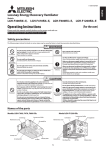
Technical manual detailing the control and operation of commercial-type Lossnay units (LGH-RX5-E Series).
Possible System Configurations
(1)
(2)
(3)
(4)
(5)
When using only the Lossnay remote controller.
Linking Lossnay and City Multi units.
Linking Mr. Slim.
Lossnay central control systems.
Linking with external equipment (BMS).
2. Applicable Models
● Lossnay (LGH-RX type)
These models have temperature sensors at return stale indoor air (RA) and outside air intake (OA) sides and can automatically switch to ventilation (Lossnay/By-pass) mode.
LGH-15RX5 -E
LGH-25RX5-E
LGH-35RX5-E
LGH-50RX5 -E
LGH-80RX5-E
LGH-100RX5 -E
LGH-150RX5-E
LGH-200RX5-E
LGH-65RX5-E
● Lossnay Remote Controller (PZ-60DR-E)
It is possible to control all of the function of LGH-RX5-E, such as, Extra-Low-fan speed, weekly timer.
Use when operating from 1 to 15 Lossnay units together at the same time.
PZ-60DR-E is not M-NET control, however, LGH-RX5-E can be use with PZ-60DR-E in the M-NET system. (Refer to page
C-78).
● Lossnay Remote Controller (PZ-41SLB-E)
Use when operating from 1 to 15 Lossnay units together at the same time. When using M-NET transmission to operate from
a centralized remote controller, use the PZ-60DR-E OR PZ-52SF-E.
It can start and stop the unit, change fan speed, and switch the ventilation mode. It also includes indicators that show errors
and when filter maintenance is required Function is limited in case of LGH-RX5-E (Refer to page C-91).
● Lossnay M-NET Remote Controller (PZ-52SF-E)
Use with Mitsubishi Electric Air conditioner Network system (MELANS) (Refer to page C-92). Because the remote controller
is power-supplied using the M-NET transmission line, it cannot be linked with Mr. Slim and other such systems that do not
use M-NET. It can start and stop the unit, change fan speed, and switch the ventilation mode. It also includes indicators that
show errors and when filter maintenance is required Function is limited in case of LGH-RX5-E (Refer to page C-92).
Please refer to the technical documentation for City Multi, Mr. Slim systems and the central controller (MELANS).
C-3
3. Terminology
● Interlocked Lossnay
A Lossnay linked to City Multi or Mr. Slim indoor units that has been set to interlocked group setting to receive signals and
operate via indoor unit’s remote controller. (Remote controller to indoor unit to Lossnay.)
● Non interlocked Lossnay
A Lossnay that is not set to interlocked group setting with City Multi or Mr. Slim indoor units. It operates using direct operating signals from the Lossnay remote controller and/or centralized remote controller.
● Ventilation Mode
Controls the Lossnay damper and permits selection of heat recovery (heat exchange), By-pass or auto modes.
● Timer control. (PZ-60DR-E)
PZ-60DR-E has weekly timer and simple timer.
• weekly timer : The operation pattern for each day of the week and the air-volume by time zone can be set (up to eight
zones per day).
• simple timer : Three setting is available , start-timer only, stop time only or start & stop.
● Delayed Operation
A Lossnay that has been set to interlocked group setting with the indoor unit will have its operation delayed for 30 minutes
after the operation of the indoor unit. When using PZ-41SLB-E, delayed operation can be set for 10, 20, 30, 40, 50 and 60
minutes.
● External Control Input
• An input signal from an external device used to operate Lossnay. It is compatible with 12V-24V DC or uncharged a-contact
signal.
• Switching High Low or Extra-Low fan speed is available by external input (CO2 sensor or other equipment is connected).
• Switching By-pass is available by external input.
● Operation Mode
Used for selecting enabling/disabling of the on/off control signal from an external device, and for setting interlocked operation
of the external device and Lossnay.
Please Refer to page C-23 for details.
(
ON/OFF interlock:
ON interlock:
OFF interlock:
External control priority:
Enables both “ON → OFF” and “OFF → ON” external signals.
Enables “OFF → ON” external signal. Disables “ON → OFF” external signal.
Enables “ON → OFF” external signal. Disables “OFF → ON” external signal.
Same as on/off interlock but the OFF signal from the remote controller is ignored when the
external control signal is ON.
● Setting Pulse Input
When the control signal from the external device outputs a pulse such as the one shown below, pulse input setting is performed by Lossnay. (Optional setting DIP switch 2-2 ON)
200 ms or more
● Operation in Cold Areas
When the outdoor air is less than -10°C, continuous fan operation for drawing in supply air is cancelled and intermittent operation is started.
● RA (Return Air)
Abbreviation for return air, which is the air drawn in from inside.
● OA (Outdoor Air)
Abbreviation for outdoor air, which is the air drawn in from outside.
C-4
4. System Features and Examples
4.1
Features
Classification
Control
Function
Item
Notes/Cautions
• Multiple unit operation
Maximum 15 units with PZ-60DR-E & PZ-41SLB-E; 16
units with PZ-52SF-E or other M-NET controllers.
• Remote controller operation
Last condition priority before turning off the unit.
• External device operation and external
pulse control
Signal : 12VDC, 24VDC, uncharged a-contact.
• External monitor signal output and supply air fan monitor output
Uncharged a-contact (external monitor/supply air fan
monitor change).
• External control operation mode setting
ON/OFF, ON, OFF and external control priority ON/OFF
mode.
• Timer control
Weekly timer & simple timer available for PZ-60DR-E.
• Delayed start
Delayed time can be varied only when the PZ-41SLB-E is
connected.
• Automatic recovery following power supply interruption (*1)
Automatic power recovery is fixed when PZ-60DR-E or
PZ-41SLB-E is connected.
• Power supply start/stop function
Function cannot be performed when PZ-41SLB-E is connected.
• High/low/Extra-Low change input
Uncharged a-contact (Remote display adaptor (PAC-SA88HA-E) is required.)
• Remote/local control change
Uncharged a-contact (Remote ON/OFF adaptor (PAC-SE55RAE) is
required.)(Function cannot be performed when using PZ-41SLB-E.)
• M-NET air conditioning operation.
Only when M-NET transmission cable is connected.
• System controller by Mitsubishi building
air control management system
Only when M-NET transmission cable is connected.
• Interlocked with Mr. Slim
Function cannot be performed with PZ-41SLB-E.
• Lossnay (heat recovery) ventilation/automatic By-pass ventilation switch
Also external By-pass switcing is available(Remote display adaptor (PAC-SA88HA-E) is required).
• For cold area operation
Installation
Maintenance
• Two non polar wires for remote controller
For PZ-60DR-E, PZ-41SLB-E connection: ø 0.65 to 1.2
PVC cable or 0.3 mm2 to 1.25 mm2 strand wire.
For M-NET connection: 1.25 mm2 to 2.00 m2 shielded
wire or equivalent.
• Address setting unnecessary
Excluding central controller system (except automatic
address).
• Test operation switch
For Lossnay single unit test operation.
• Filter maintenance display
(remote controller display)
Filter, core maintenance display for PZ-60DR-E.
• Inspection display
(remote controller, control board LED)
Error code indication for PZ-60DR-E.
• M-NET power supply display
(control board LED)
*1 The operation condition is saved, and when the power is turned off and then back on, the operation condition returns to the
previous requested condition. (When using PZ-60DR-E, PZ-41SLB-E, the start/stop condition from an external device is not
saved.)
C-5
4.2
System Examples
Basic System (Refer to page C-11)
One Lossnay with one remote controller
Multiple Lossnay units with one remote controller
Lossnay
Non-polar
Two wires
Lossnay
Non-polar
Two wires
Lossnay
Power supply
Lossnay
Remote
controller
PZ-60DR-E or
PZ-41SLB-E
Remote controller
PZ-60DR-E or PZ-41SLB-E
Power supply
(Sub)
Remote controller
PZ-60DR-E or PZ-41SLB-E
Power supply
● Up to 15 Lossnay units can be controlled at
one time with one remote controller.
● Lossnay can be controlled from two remote
locations.
● The remote controller gives priority to the last
operation function request.
Operating with an external device
Operating with Mr. Slim
Lossnay
Operating with an External Device
(Refer to page C-22)
Operation with an Air Conditioning Unit
(Refer to page C-13)
Non-polar
Two wires
(Main)
Power supply
● A simple system in which Lossnay is operated
independently with one remote controller.
Two remote controller system with one Lossnay
Power supply
Power supply
Remote
controller
Mr. Slim
(indoor unit)
● The Lossnay remote controller (PZ-60DR-E, PZ-41SLB-E) cannot be
used with this system.
● Use MA remote controller of Mr.Slim for switching Lossnay ON/OFF or
the fan speed.
● The ventilation mode is “automatic ventilation”.
● Selection of interlocked operation
mode is possible.
● Delayed start interlocked operation is
possible.
Lossnay
Non-polar
Two wires
Power supply
Remote controller
PZ-60DR-E or
PZ-41SLB-E
Power supply
Indoor unit
Remote controller
● Lossnay operation will be performed via the external device.
● Level signal or pulse signal input (12V DC, 24V DC, uncharged a-contact) is possible.
Air conditioning device and system control
C-6
City Multi and Lossnay Interlocked System
Indoor
unit
Lossnay
Indoor
unit
MA remote controller
Interlock-Group 1
Lossnay
Indoor
unit
MA remote controller
Indoor Lossnay
unit
MA remote controller
Interlock-Group 2
Interlock-Group 3
Refrigerant 1
Indoor
unit
Lossnay
MA remote controller
Interlock-Group 4
Indoor
unit
MA remote controller
Interlock-Group 5
・・・Group setting
Refrigerant 2
Outdoor unit
Outdoor unit
Interlocked
・・・
operation setting
Lossnay
Lossnay
Indoor
unit
MA remote
controller
Interlock-Group 1
Indoor
unit
Indoor
unit
MA remote controller
Interlock-Group 2
Indoor unit Indoor
unit
MA remotecontroller
Lossnay
Interlock-Group 3
● One Lossnay can be interlocked with 16 indoor units. In addition, PZ-60DR-E (non M-NET) can be connected for each Lossnay units.
Centralized controller
Centralized Management System
M-NET System
Outdoor unit
Power Lossnay
supply
unit
Lossnay
remote controller
PZ-60DR-E
Group 1
●
●
●
●
Lossnay
Group 2
Lossnay Lossnay Lossnay
Lossnay
Lossnay
Lossnay
Lossnay
remote controller
PZ-60DR-E
Group 3
Lossnay
remote controller
PZ-60DR-E
Group 4
Lossnay
remote controller
PZ-60DR-E
Group 5
Detailed control such as start/stop, fan speed Extra-Low and ventilation mode control is possible from the Lossnay remote controller PZ-60DR-E.
PZ-52SF-E (M-NET remote controller) can be used instead of PZ-60DR-E. However, function is limited and connecting position is different.
Start/stop, fan speed and ventilation mode control is possible from the centralized controller.
Controller can set up the group including maximum of 16 indoor or Lossnay units.
Two remote controller system with multiple Lossnay units
Use Lossnay remote controller PZ-60DR-E or PZ-41SLB-E .
(Do not use PZ-52SF-E).
Lossnay transmission connection terminal
Power supply
Remote controller input terminal
2
1
Power supply
TM4 PZ-60DR-E
Remote controller
PZ-60DR-E or
PZ-41SLB-E
Transmission wires
● It is also possible to operate two remote controller units when using multiple Lossnay units.
Setting
Change the setting on the main/sub switch (SW1) on the second
and subsequent Lossnay units to “Sub”.
Interlocking multiple units
When the operation signal is an uncharged a-contact signal
Lossnay
(Main)
Power
supply
Lossnay
A/C
Power supply
A/C
Power supply
A/C
Power supply
Remote controller
(PZ-60DR-E or PZ-41SLB-E)
Power
External
supply
device
Operating switch
for external device
Power supply
Main/Sub selection
switch
(SW1)
Main Sub
(Factory setting: main)
Lossnay (Sub)
Remote controller
PZ-60DR-E or
PZ-41SLB-E
Air conditioning
unit side remote
controller
Air conditioning Air conditioning
unit side remote unit side remote
controller
controller
First Lossnay
Power
supply
TM4
Lossnay (Sub)
● Interlocking is possible from multiple air conditioning units, etc.
(excluding pulse input)
(Separately sold parts are necessary depending on the operation signal).
TM4
1 2
1 2
Connect to
remote
controller
Second (PZ-60DR-E)
Lossnay
Connect
to third
Lossnay
Power
supply
MAX 15 units
Transmission cable
Interlocking/individual combined systems
Use Lossnay remote controller PZ-60DR-E .
Interlock settings are possible with the inclusion of a group setting.
(Joint use of the air conditioner remote controller and Lossnay remote
controller is possible.)
(Do not use PZ-41SLB-E).
Lossnay transmission connection terminal
M-NET transmission cable
input terminal block
TB5
A BS
Shielded wire
Operation settings
M-NET
transmission cable
and PZ-52SF-E
Centralized
controller
Outdoor
(000)
unit (51)
Indoor unit of
air conditioner
(01)
Remote controller
input terminal
2
1
Lossnay (02)
TM4 PZ-60DR-E
Transmission wires
MA remote
controller
Lossnay remote
controller
(PZ-60DR-E)
Group 1
Group 2
( ) address
Address Setting
SA1
SA2
10 digit
1 digit
Address setting switch
● Applicable indoor units are C type or later (for use with MA remote controller) models
● Set the different groups of indoor unit of air conditioner and Lossnay unit.
● When the address number has been changed, the data in the memory is
automatically reset.
C-7
4.3
System Selection
Interlocked with City Multi
(Refer to page C-14)
Lossnay operation when indoor unit is stopped
●
Lossnay stopping when indoor unit is operating
●
Switching Lossnay fan speed
When interlocked with indoor unit for compatibility with both R22, R407C and R410A
High/Low
When interlocked with indoor unit for other than the above
Fixed to high
Ventilation mode
Fixed to automatic
Filter maintenance indicator
●
Lossnay error indicator
●
Delayed operation
●
External control operating mode selection
×
Number of indoor units for interlocked group setting with one Lossnay unit
16 units
Number of Lossnay units for interlocked group setting with one indoor unit
One unit
* All Lossnay functions including Extra-Low fan speed can be controlled from PZ-60DR-E.
Interlocked with Mr. Slim
Incase of PZ-60DR-E
Air
conditioner
Air
conditioner
MA remote
controller
Lossnay
M-NET transmission cable
PZ-60DR-E can be used
Incase of PZ-52SF-E
Air
conditioner
Air
conditioner
MA remote
controller
Lossnay
M-NET transmission cable
PZ-52SF-E can be used
(Refer to page C-13)
When using A-control remote controller
Lossnay operation when indoor unit is stopped
Lossnay stopping when indoor unit is operating
Lossnay fan speed switching
Other common items
Lossnay error indicator
Ventilation mode
Filter maintenance indicator
Delayed operation
External control operating mode selection
Number of indoor units for interlocked group setting with one Lossnay unit
Number of Lossnay units for interlocked group setting with one indoor unit
●
×
High/Low
×
Fixed to automatic
×
●
×
One unit
One unit
Mr.Slim (A-control)
indoor unit
Lossnay unit
LGH-RX type
Remote controller
Lossnay remote
controller
PZ-60DR-E,
PZ-41SLB-E
cannot be used.
Slim-Lossnay connecting cable
(Enclosed accessory with Lossnay unit)
Independent Lossnay Unit (Not interlocked with
City Multi or Mr. Slim systems.) (Refer to page C-11)
●
High/Low/Extra Low
Heat ex. /
Ventilation mode
By-pass/ Auto
Filter maintenance indicator
●
Lossnay error indicator
●
Delayed operation
●
External control operating mode selection
●
Number of Lossnay units
15 units
Number of remote controllers
Two units
* All Lossnay functions including Extra-Low fan speed can be controlled from PZ-60DR-E.
Start/Stop
Fan speed switching
Lossnay unit
LGH-RX type
Lossnay remote controller
(PZ-60DR-E, PZ41SLB-E)
External signal source
for interlocking
to the Lossnay
Interlocked with external device (BMS) (Refer to page C-22)
Start/Stop
Fan speed switching
Ventilation mode switching
Filter maintenance indicator
Lossnay error indicator
Delayed operation
External control operating mode selection
* ● : Available
× : Not Available
C-8
●
Fixed to high
Fixed to automatic
×
×
●
●
External signal source
for interlocking
to the Lossnay
Lossnay unit
LGH-RX type
Centralized Controller System
Centralized controller
AG-150A
Outdoor unit
Interlocked with
City Multi indoor units
Indoor unit
LOSSNAY RX5
Indoor unit
Power supply unit
(PAC-SC51KUA)
M-NET remote
controller
M-NET remote
controller
LOSSNAY remote
controller
PZ-60DR-E
Interlocked with
Mr. Slim indoor units
Mr.Slim
outdoor unit
Mr.Slim
indoor unit
LOSSNAY RX5
Mr.Slim
remote controller
LOSSNAY units only
Central Controller System
LOSSNAY RX5
LOSSNAY RX5
LOSSNAY remote
controller
PZ-60DR-E
LOSSNAY remote
controller
PZ-60DR-E
Interlocked with
external devices
LOSSNAY RX5
Ext. signal source
LOSSNAY remote
controller
PZ-60DR-E
C-9
Reference: Remote controller for the Lossnay and indoor unit
Refer to the technical documentation related to the Remote controller for the indoor unit.
Remote controllers for Lossnay unit
Lossnay remote controller
(PZ-60DR-E)
Lossnay remote controller
(PZ-41SLB-E)
Lossnay M-NET remote controller
(PZ-52SF-E)
*non M-NET protocol
With Lossnay interlock switches
and indicators.
*non M-NET protocol
Advanced Lossnay remote controller.
Without Lossnay interlock switches
and indicators.
2CONTROLLERS INTERLOCKED
AUTO
BY-PASS HEAT EX.
CENTRAL INTERLOCKED
HEAT EX.
BY-PASS
AUTO
CHECK
NOT AVAILABLE FILTER
FILTER
MIN. DELAYED
CHECK
SETTING
ON/OFF
FILTER
DELAY START
FILTER
PZ-41SLB-E
Remote controllers for City Multi indoor unit
MA remote controller (PAR-21MAA)
ME remote controller (PAR-F27MEA)
*non M-NET protocol
With Lossnay interlock switches and indicators.
Without Lossnay interlock switches and indicators.
CENTRALLY CONTROLLED
ON OFF
DAILY
AUTO OFF
CLOCK
TIME SUN MON TUE WED THU FRI SAT
TIMER
Hr
AFTER
ON
AFTER OFF
ERROR CODE
TEMP.
MENU
PAR-21MAA
MONITOR/SET
STAND BY
DEFROST
ON/OFF
ON/OFF
1Hr.
FILTER
CHECK MODE
TEST RUN
REMAINDER
FILTER
WEEKLY
SIMPLE
AUTO OFF
ONLY1Hr.
BACK
FUNCTION
ERROR CODE
NOT AVAILABLE
TEMP.
CLOCK→ON→OFF
FILTER
FILTER
DAY
CHECK
TEST
CHECK TEST
CLOCK
OPERATION
CLEAR
PAR-F27MEA
TIMER SET
Remote controllers for Mr. Slim indoor unit
PAR-21MAA
TIME SUN MON TUE WED THU FRI SAT
TIMER
Hr
AFTER
ON
AFTER OFF
ERROR CODE
TEMP.
MENU
BACK
PAR-21MAA
MONITOR/SET
FUNCTION
FILTER
WEEKLY
SIMPLE
AUTO OFF
ONLY1Hr.
C-10
LIMIT TEMP.
ON/OFF
ON/OFF
ON/OFF
FILTER
DAY
CLOCK
CHECK
OPERATION
CLEAR
TEST
4.4
Basic System
4.4.1 System Summary
Design Example 1 Basic system
Non-polar
Two wires
Design Example 2 Lossnay control of multiple units
Non-polar
Two wires
Lossnay
● Up to 15 Lossnay units can be
controlled at one time with one
remote controller switch.
Lossnay
(Main)
Power supply
Lossnay
Power supply
Remote
controller
PZ-60DR-E or
PZ-41SLB-E
Remote controller
PZ-60DR-E or PZ-41SLB-E
● This is a simple system.
A Lossnay is operated independently
with one remote controller.
(Sub)
Power supply
Design Example 3 Two remote controllers system
Non-polar
Two wires
Lossnay
● The Lossnay can be controlled
from two remote locations.
● The remote controller gives priority to the last touch.
Power supply
Remote controller
PZ-60DR-E or PZ-41SLB-E
4.4.2 Operation of Multiple Units
Feature
Ordered part
Notes
One remote controller can operate from one to 15 Lossnay units. PZ-60DR-E has many functions.such
as Extra-Low fan speed, however, PZ-41SLB has limited function.
Remote controller
PZ-60DR-E, PZ-41SLB-E
• Also connect the power to the second and following Lossnay units.
• The maximum extension of the transmission cable is 500 m or less (between Lossnay and remote
controller switch, between Lossnay and Lossnay).
• The main or Sub setting on the Lossnay is necessary.
When operating multiple Lossnay units
Lossnay
(Main)
Power
supply
Remote controller
(PZ-60DR-E or PZ-41SLB-E)
Power
External
supply
device
Operating switch
for external device
Main/Sub selection
switch
(SW1)
Main Sub
(Factory setting: main)
Lossnay (Sub)
(1) Connect from Lossnay Unit 1 to Lossnay Unit 2, and from
Unit 2 to Unit 3 and so on up to a maximum of 15 units
using a transmission cable (PVC insulated PVC jacketed
and either between 0.65 and 1.2, or between 0.3 mm2 and
1.25 mm2 in cross section).
(2) Change the setting on the main/sub switch (SW1) on the
second and subsequent Lossnay units to “Sub”.
CAUTION:
Don’t tighten screws of terminal block with a torque larger than
0.5 Nm. It could damage the PCB.
First Lossnay
Power
supply
TM4
Lossnay (Sub)
TM4
1 2
1 2
Connect to
remote
controller
Second (PZ-60DR-E)
Lossnay
Connect
to third
Lossnay
Power
supply
MAX 15 units
Transmission cable
Note:
● Up to four 0.3 mm2 stranded wires or 0.65 PVC wires can
be connected to one input terminal.
● For other types of wire, up to two can be connected.
● The operation signal and pulse signal can be connected to
the external device of the main Lossnay only.
● Connect the power to each respective Lossnay unit.
● When the LGH-150RX5 and LGH-200RX5 types are connected, they operate at low fan speed even if extra low fan speed
is selected.
C-11
4.4.3 Operation with two Remote controllers
Characteristics
Remote controller
Note
• Lossnay can be operated from two remote locations.
• Lossnay conditions can be checked from two remote Lossnay remote controller
locations.
PZ-60DR-E, PZ-41SLB-E
• The remote controller gives priority to the last touch.
• Use only up to two remote controllers
(Operation will not go normally if three
remote controller switches are connected.)
System Example
Transmission
cable extension
is 500 m or less
0.65 to 1.2
PVC cable or
0.3 mm2 to 1.25 mm2
strand wire.
Lossnay
Lossnay
MAX 15 units.
Power supply
Power supply
Remote controller
PZ-60DR-E or PZ-41SLB-E
Lossnay
Lossnay
MAX 15 units.
Power supply
Transmission
cable extension
is 500 m or less
0.65 to 1.2
PVC cable or
0.3 mm2 to 1.25 mm2
strand wire.
Power supply
Remote controller
PZ-60DR-E or PZ-41SLB-E
Lossnay
Lossnay
Power supply
Remote controller
PZ-60DR-E or
PZ-41SLB-E
Power supply
Remote controller
PZ-60DR-E or
PZ-41SLB-E
Operation Method
The operation is the same with each remote controller. In this case, the Lossnay gives operating priority to the last button push.
C-12
4.5
Interlocking with Mr. Slim
4.5.1 Interlocked Mr. Slim and Lossnay System
Features
● It is possible to Interlock Mr. Slim indoor units with Lossnay operation.
System Example
Mr. Slim outdoor unit
Mr.Slim indoor unit
Lossnay unit
LGH-RX type
Remote controller
Slim-Lossnay
connection cable
(Enclosed accessory with Lossnay unit)
Lossnay Function Table (Interlocked settings)
Details
Item
Number of indoor units that can be set to interlocked operation with one Lossnay unit in each group
One unit
Number of Lossnay units that can be set to interlocked operation with one indoor unit
One unit
Operation of Lossnay unit only
(When indoor unit is stopped)
Possible
Independent Lossnay unit start and stop
(When indoor unit is operating)
Not possible
Delayed operation
(Optional setting)
30 minutes delayed operation of Lossnay when indoor unit
cooling/heating operation is started (Lossnay Dip-SW setting).
Switching fan speed
High/Low
Ventilation mode
Fixed to automatic
Filter indicator
Not possible
Error
Not possible
Restrictions and precautions
* The Lossnay remote controller (PZ-60DR-E, PZ-41SLB-E)
cannot be used on systems interlocked with Mr. Slim.
C-13
4.6
Combining with City Multi
4.6.1 Independent Lossnay System with Lossnay M-NET Remote
Controller and MELANS
Features
● The Mitsubishi Electric air-conditioner network system (MELANS) can operate and monitor each group of Lossnay units and
City Multi indoor units.
● Can also use the Lossnay M-NET remote controller to operate.
System Examples: 1 (Lossnay Non M-NET Remote Controller PZ-60DR-E)
The following groups can be configured.
Centralized controller (000)
( ) address
M-NET
Power
supply
unit
Lossnay
(001)
Lossnay
(002)
Lossnay remote
controller PZ-60DR-E
Group1
Lossnay
(003)
Lossnay
(004)
Lossnay
(005)
Lossnay remote
controller PZ-60DR-E
Group2
Lossnay
(006)
Lossnay
(007)
Lossnay remote
controller PZ-60DR-E
Group3
Group4
Lossnay
(008)
Lossnay remote
controller PZ-60DR-E
Group5
M-NET
Outdoor unit
(059)
Indoor
unit
(009)
Lossnay
(010)
Indoor
unit
(011)
MA Remote
MA Remote Lossnay remote
controller
controller PZ-60DR-E controller
Group7
Group6
Group 1
Group 2
Group 3
Group 4
Group 5
Group 6
Group 7
Group 8
Group 9
:
:
:
:
:
:
Indoor
unit
(012)
Lossnay
(013)
Lossnay
(014)
Lossnay
(015)
Lossnay remote
Lossnay remote
controller PZ-60DR-E controller PZ-60DR-E
Group8
One Lossnay unit and one Lossnay remote controller.
Without a Lossnay remote controller.
Multiple Lossnay units and one Lossnay remote controller.
One Lossnay unit and two Lossnay remote controllers.
Multiple Lossnay units and two Lossnay remote controllers.
One Lossnay unit is interlocked to one indoor unit(PZ-60DR-E is not
necesally).
: One Lossnay unit is interlocked to multiple indoor units(PZ-60DR-E is
not neccesally).
: Multiple Lossnay units connected to indoor unit transmission cable
side and one Lossnay remote controller.
: Without Lossnay units.
Indoor
unit
(016)
MA Remote
controller
Group9
・・・Group setting
Interlocked
・・・operation setting
Caution:
● Hard wire connection from PZ-60DR-E is required independent from M-NET line. If change the Group setting in the future, it
is required to change the wiring of PZ-60DR-E.
● In this application, Lossnay remote controller PZ-41SLB-E cannot be used.
C-14
System Examples: 2 (Lossnay M-NET Remote Controller PZ-52SF-E)
The following groups can be configured.
● Further information please refer LGH-RX4 Technical Manual.
Centralized controller (000)
Power
supply
unit
( ) address
Lossnay
(001)
Lossnay
(002)
(101)
Group1
Outdoor unit
(059)
Indoor
unit
(009)
MA Remote
controller
Group 7
Group 8
Group 9
:
:
:
:
:
:
Lossnay
(005)
Lossnay
(006)
Lossnay
(010)
(156)
Lossnay M-NET remote
controller PZ-52SF-E
Group3
Indoor
unit
(011)
Lossnay
(007)
(106)
Lossnay M-NET remote
controller PZ-52SF-E
Group2
Group6
Lossnay
(004)
(103)
Lossnay M-NET remote
controller PZ-52SF-E
Group 1
Group 2
Group 3
Group 4
Group 5
Group 6
Lossnay
(003)
Group4
Indoor
unit
(012)
Lossnay
(013)
MA Remote
controller
Group7
One Lossnay unit and one Lossnay M-NET remote controller.
Without a Lossnay M-NET remote controller.
Multiple Lossnay units and one Lossnay M-NET remote controller.
One Lossnay unit and two Lossnay M-NET remote controllers.
Multiple Lossnay units and two Lossnay M-NET remote controllers.
One Lossnay unit is interlocked to one indoor unit.(PZ-60DR-E is not
necesally)
: One Lossnay unit is interlocked to multiple indoor units.(PZ-60DR-E is
not neccesally)
: Multiple Lossnay units connected to indoor unit transmission cable
side and one Lossnay M-NET remote controller.
: Without Lossnay units.
Lossnay
(008)
(107)
(157)
Lossnay M-NET remote
controller PZ-52SF-E
Group5
Lossnay
(014)
Lossnay
(015)
Indoor
unit
(016)
MA Remote
controller
Lossnay M-NET remote
controller PZ-52SF-E (114)
Group8
Group9
・・・Group setting
Interlocked
・・・operation setting
Caution:
● If change the Group setting in the future, no need to change the M-NET wiring, Just change the address setting from centralized controller.
● In this application, Lossnay remote controller PZ-41SLB-E cannot be used.
C-15
Lossnay Function Table (Group Setting)
Item
Details
Number of Lossnay remote controllers and/or MELANS
remote controllers that can be connected to one Lossnay unit
Five units
(Number of Lossnay remote controller(PZ-60DR-E or PZ52SF-E) is two units max.)
Operation of two remote controllers in one group
Possible
Switching fan speed
High/Low (Extra-Low from PZ-60DR-E)
Ventilation mode
Heat exchange / By-pass / Automatic
Filter maintenance indicator
3000 hours / No display
Error
Display
Controller Function Table
Local Remote
Model
MELANS Series
Lossnay Lossnay
Simple
Group
System
ON/OFF
Remote
Centralized
Schedule
remote
remote
remote
remote
remote
remote
controller
controller
timer
controller controller
controller controller controller
controller
PZ-52SF-E PZ-60DR-E PAR-21MAA PAC-SE51CRA
PAC-SC30GRA PAC-SF44SRA PAC-YT34STA PAC-YT40ANRA
(M-NET)
PAR-F27MEA PAC-YT51CRA
Scheduling/
Recording
Monitoring
Operation
No. of controllable (Groups/Units)
1 Group/16 Units 1 Group/15 Units
AG-150A
50 Group/50 Units 50 Group/50 Units 16 Group/50 Units 50 Group/50 Units
n
n
×
×
«
n
n
n
×
×
n
n
n
×
×
n
*1
×
n
Status (Operation/Stop)
«
«
n
n
n
n
Switching air volume
«
«
«
×
×
«
Ventilation mode
«
«
«
×
×
«
Error
«
«
Error information
«
«
n
n
n
n
«
×
n
n
Start/Stop
«
«
Switching air volume
«
«
Switching Ventilation mode
«
Priority instructions to local remote
controller (Local permitted)
Not applicable with non-interlocked
Lossnay units
Filter maintenance indicator
«
«
«
×
×
«
Local permitted
«
«
«
×
×
«
Weekly
×
«
×
«
×
«
Stop/Starts per day
×
16
×
16
×
24
Stop/Starts per week
×
112
×
112
×
24x7*2
Minimum setting (minutes)
×
1
×
5
×
1
Error record
×
«
«
×
×
«
Switches and display
n: Group/batch
« : Group only (or function available)
: Available under some condition
× : Not available
*1 Available as a scheduled operation
*2 You can set a schedule for the year and a weekly schedule for individual seasons.
● For details about the operation and display of the Lossnay remote controller (PZ-60DR-E), Refer to page C-78.
● For details about the operation and display of the Lossnay M-NET remote controller (PZ-52SF-E), Refer to page C-92.
● For details about the operation and display of the centralized controller (AG-150A), Refer to page C-93.
C-16
4.6.2 City Multi and Lossnay Interlocked System
Characteristics
● It is possible to interlock City Multi indoor units with Lossnay operation.
● Independent Lossnay operation can also be performed using MA remote controller or ME remote controller.
● Non M-NET Lossnay remote controller PZ-60DR-E can be used with any Lossnay units in this application.
System Examples
The following groups can be configured.
Single Refrigerant System
Outdoor unit (051)
Non M-NET Lossnay remote controller PZ-41SLB-E
cannot be used with any group in this application.
( ) address
Indoor
unit
(001)
Lossnay
(002)
MA Remote
controller
MA Remote
controller
Group1
Group 1
Group 2
Group 3
Group 4, 5
Indoor Lossnay
(005)
unit
(004)
Indoor
unit
(003)
Lossnay
(007)
Indoor
unit
(008)
Lossnay
(009)
Indoor
unit
(010)
MA Remote
controller
MA Remote
controller
Group2
:
:
:
:
Indoor
unit
(006)
MA Remote
controller
Group4
Group3
・・・Group setting
Interlocked
・・・operation setting
Group5
One Lossnay unit is interlocked to one indoor unit.
One Lossnay unit is interlocked to multiple indoor units.
One indoor unit with two remote controllers is interlocked to one Lossnay unit.
Multiple groups are interlocked to one Lossnay unit.
Multiple Refrigerant Systems
( ) address
Refrigerant 1
Refrigerant 2
Outdoor unit (051)
Indoor
unit
(001)
MA Remote
controller
Group1
Group 1
Group 2
Group 3
Lossnay
(002)
Outdoor unit (055)
Indoor
unit
(003)
MA Remote
controller
Group2
Lossnay
(004)
Indoor
unit
(005)
Indoor
unit
(006)
Indoor Lossnay
(008)
unit
(007)
MA Remote
controller
・・・Group setting
Interlocked
・・・operation setting
Group3
: One Lossnay unit is interlocked to one indoor unit.
: One Lossnay unit is interlocked to multiple indoor units (with different refrigerants).
: One Lossnay unit is interlocked to multiple indoor units (with same refrigerant).
C-17
Lossnay Function Table (Interlocked Settings)
Details
Item
Number of indoor units that can be set to interlocked operation with one Lossnay unit in each group
16 units per group
Number of Lossnay units that can be set to interlocked operation with one indoor unit
one unit
Independent Lossnay start/stop operation
Possible
Delayed operation
(Optional setting by Lossnay PCB)
30-minutes delayed operation when indoor unit cooling/heating operation is started
Fan speed switching
Indoor unit compatible with both R22,
R407C and R410A
High/Low
Units other than the above
Fixed to high
Ventilation mode
Fixed to automatic
Filter maintenance indicator
3000 hours / No display
Error
Display
Restrictions and precautions
* Lossnays cannot be interlocked to the indoor units using
K-transmission converter.
Note:
● In case of PZ-60DR-E is installed, additional function is available.
Lossnay Controller Function Table
Local Remote
Model
MELANS Series
Lossnay Lossnay
Simple
Group
System
ON/OFF
Remote
Schedule
Centralized
remote
remote
remote
remote
remote
remote
controller
timer
controller
controller controller
controller controller controller
controller
PZ-52SF-E PZ-60DR-E
PAR-21MAA PAC-SE51CRA PAC-SC30GRA PAC-SF44SRA PAC-YT34STA PAC-YT40ANRA AG-150A
PAR-F27MEA PAC-YT51CRA
Scheduling/
Recording
Monitoring
Operation
No. of controllable (Groups (G)/Units) 1 Group/16 Units 1 Group/15 Units 1 Group/16 Units 1 Group/16 Units 8 Group/16 Units 50 Group/50 Units 50 Group/50 Units 16 Group/50 Units 50 Group/50 Units
Start/Stop
«
«
«
«
n
n
n
n
n
Switching air volume
«
«
«
×
«
«
×
×
«
Switching ventilation mode
«
«
×
×
×
×
×
×
×
Prohibit Local
×
×
×
×
×
n
×
n
Status (Operation/Stop)
«
«
«
×
«
*1
n
n
n
Switching air volume
«
«
«
×
«
×
×
×
«
Ventilation mode
«
«
×
×
×
×
×
×
×
Error
«
«
«
«
«
«
«
«
n
n
n
n
n
Error information
n
n
×
n
n
Filter maintenance indicator
«
«
«
×
«
«
×
×
«
Permit/Prohibit for remote control
×
«
«
«
«
«
×
×
«
Weekly
×
«
×
×
×
×
«
×
«
Stop/Starts per day
×
16
2
×
×
×
16
×
24
Stop/Starts per week
×
112
×
×
×
×
112
×
24x7*3
Minimum setting (minutes)
×
1
10
×
×
×
5
×
1
Error record
×
«
×
×
×
«
×
×
«
Switches and display
*2
n: Group/batch
« : Group only (or function available)
: Available under some condition
× : Not available
*1 Does not display which interlocked Lossnay unit is operating in which group
*2 Available as schedule operation
*3 You can set a schedule for the year and a weekly schedule for individual seasons.
● For details about the operation or display of the remote controller (PAR-F27MEA, PAR-21MAA), please refer to the specific
remote controller manuals.
C-18
4.6.3 MA Remote Controller/ME Remote Controller in Combination
with Lossnay Non-M-NET Remote Controller (PZ-60DR-E)
System
Combining MA, ME and Lossnay Non M-NET remote controllers is permitted.
● In case of combination with Lossnay M-NET remote controller (PZ-52SF-E) please refer LGH-RX4 Technical Manual.
Combining Indoor Unit of Air Conditioner Remote Control and Lossnay Remote Control
Indoor Unit
Lossnay LGH-RX5 type
Model for MA remote control (Type C or later)
«
Model for other than MA remote control (Type B or earlier)
×
« : Compatible × : Incompatible
System Examples: 1
Centralized controller (000)
Interlocked operation setting
Power
supply
unit
Indoor unit of
air conditioner
(001)
Outdoor unit
(051)
MA remote
controller
(101)
G
Lossnay
(002)
Lossnay remote
controller
PZ-60DR-E
G
( ) address
Setting Method
(1) Make the Group setting for the indoor unit.
(2) Make the Group setting for the Lossnay unit.
(3) Set the indoor unit and Lossnay unit for interlocked operation.
When using the centralized controller, make both the Group setting and operation setting with centralized controller.
Characteristics
(1) When the indoor unit is set for interlocked operation in one group:
Interlocked Lossnay operation is possible with indoor unit remote controller. In this case, operation can switch between
High/Low/Off. It is possible to switch Lossnay operation only between High/Low/Off with the indoor unit remote controller.
It is possible to controll the Lossnay unit from Lossnay remote controller PZ-60DR-E. More additional function such as Extra
Low fan speed is available.
(2) When two or more indoor units in different groups are set for interlocked operation, the Lossnay will operate if at least one
group operates. The Lossnay will stop operation if all groups stop operation.
It is possible to switch the Lossnay only between High/Low when other groups are operating with indoor unit remote controller.
It is possible to controll the Lossnay unit from Lossnay remote controller PZ-60DR-E. More additional function such as Extra
Low fan speed is available.
Note:
● If the display on the MA, ME or other indoor unit remote controllers is cancelled, the indoor unit remote controller will not
show the ventilation display even if Lossnay is operating via the Lossnay remote controller PZ-60DR-E.
Note:
Power supply limitation of transmission cable for indoor unit.
● Indoor units + ME remote controllers (compact remote controllers) is less than or equal to 40 units.
● Indoor units are less than or equal to 20 units.
(MA remote controllers and Lossnay units are not included in the 20 units, listed above.)
C-19
System Examples: 2
A sophisticated system including City Multi can also be configured.
Centralized controller (000)
( ) address
M-MET
Power
supply
unit
Outdoor unit
(059)
Lossnay
(001)
Lossnay
(002)
Lossnay remote
controller PZ-60DR-E
Group1
Lossnay
(003)
Lossnay
(004)
Lossnay
(005)
Lossnay
(006)
Lossnay remote
controller PZ-60DR-E
Group2
Lossnay
(007)
Lossnay remote
controller PZ-60DR-E
Group3
Lossnay(008)
Lossnay remote
controller PZ-60DR-E
Group4
Group5
M-MET
Indoor unit
(009)
Lossnay
(010)
Indoor unit
(011)
(109)
ME
remote controller
Group6
Lossnay remote
controller PZ-60DR-E
Indoor unit
(012)
Lossnay
(013)
Lossnay
(014)
Lossnay
(015)
(111)
ME
remote controller
Group7
Indoor unit
(016)
(116)
Lossnay remote
controller PZ-60DR-E
Lossnay remote
controller PZ-60DR-E
Group8
ME
remote controller
Group9
・・・Group setting
Interlocked
・・・operation setting
Group 1
Group 2
Group 3
Group 4
Group 5
Group 6
Group 7
Group 8
Group 9
:
:
:
:
:
:
:
:
One Lossnay unit and one Lossnay remote controller.
Without Lossnay remote controller.
Multiple Lossnay units and one Lossnay remote controller.
One Lossnay unit and two Lossnay remote controllers.
Multiple Lossnay units and two Lossnay remote controllers.
One Lossnay unit is interlocked to one indoor unit. (PZ-60DR-E is not necessary)
One Lossnay unit is interlocked to multiple indoor units. (PZ-60DR-E is not necessary)
Multiple Lossnay units connected to an indoor unit transmission cable
and one Lossnay remote controller.
: Without Lossnay units.
Note:
● Hard wire connection from PZ-60DR-E is required independent from M-NET line. If change the Group setting in the future, it
is required to change the wiring of PZ-60DR-E.
● Do not use Lossnay remote controller PZ-41SLB-E.
C-20
4.6.4 When Using the LONWORKS® Compatible Adaptor (LMAP02-E)
to Connect to LONWORKS®
By using the LON® adaptor (model name: LMAP02-E) to connect to LONWORKS®, it is possible to control and observe Lossnay
operation on a building management system.
* For specifications and functions of the LON® adaptor, refer to the materials regarding the LONWORKS® compatible adaptor.
Table of Functions
Individual Lossnay
(Lossnay not set
for interlocked
operation)
Contents
Operation
Monitoring
Interlocked Lossnay
(Lossnay set for
interlocked operation with City Multi)
«
«
«
«
«
«
«
«
«
«
ON/OFF
Switch fan to High/Low
Switch ventilation mode
Prohibit local ON/OFF operation
Operation condition
Fan speed
Ventilation mode (conditions)
Errors
Filter maintenance indicator
Prohibit local ON/OFF operation
« : Available
×
×
×
×
×
×
×
«
×
×
×: Not Available
System Example
(Using M-NET)
M-NET
Building
management
system
LMAP02-E
Lossnay
LONWORKS
Lossnay
remote controller
PZ-60DR-E
Lossnay
Lossnay
remote controller
PZ-60DR-E
LMAP02-E
M-NET
Lossnay
Lossnay
remote controller
PZ-60DR-E
Lossnay
Lossnay
remote controller
PZ-60DR-E
Connect the M-NET transmission cable to TB5 A,B of the Lossnay terminal block. (Refer to page C-71).
The Lossnay remote controller (PZ-41SLB-E) cannot be used with this system.
Up to 50 units can be connected with one LMAP02-E.
For details about the system or connection cables of the LMAP02-E, refer to its technical materials.
*
LONWORKS® is a registered international trademark, registered in the U.S.A. to the Echelon Corporation.
C-21
5. Examples of Applications Using Various
Input and Output Terminals
Various applications are possible by using the input/output terminals and connectors as shown below.
Input/Output Specifications
Terminal
Specification
Page
TM2 is the input terminal block for start/stop the Lossnay unit using external
equipment, such as a Mr. Slim (A-control) indoor unit or the BMS (Building
Management System).
Use voltage (12V-24V DC) or uncharged a-contact for signal input.
(Both voltage and no-voltage signals are compatible with pulse input; a pulse
signal duration of 200 ms or more is needed. Set DIP switch 2-2 to ON.)
C-26/C-27
C-28/C-73
Output terminal during Lossnay unit operation. (uncharged a-contact signal output.)
Output delay function 1 is possible by DIP switch 2-8
Contactor rating:
Max 240V AC, 2A
24V DC,
2A
Min 220V AC, 100mA
5V DC,
100mA
C-26/C-27
C-70/C-74
Output terminal during Lossnay unit malfunction. (uncharged a-contact signal output.)
Contactor rating:
Max 240V AC, 1A
24V DC,
1A
Min 220V AC, 100mA
5V DC,
100mA
C-26/C-27
C-26/C-27
C-75
(TM3 6 7)
Output terminal during Lossnay unit malfunction. (uncharged a-contact signal output.)
Output delay function 2 is possible by DIP switch 5-6
Contactor rating:
Max 240V AC, 1A
24V DC,
1A
Min 220V AC, 100mA
5V DC,
100mA
5
External control input
connector for By-pass
(CN 16)
Input connector for switching By-pass.
Establish the wire connection by inserting the optional remote display adaptor
(PAC-SA88HA-E) in the connector CN16 (Ventilation mode selector).
C-28/C-29
C-70
6
External control input
connector for fan speed
(CN 16)
Input connector for switching Hight/Low/Extra-Low fan speed.
Using marketed CO2 sensor, etc., make connection by inserting the optional
remote display adaptor (PAC-SA88HA-E) in the connector CN16.
C-28/C-70
1
External control input
terminal block for
start/stop the Lossnay
unit
(TM2 1 2 3)
2
Lossnay operation monitor output terminal block
or
Output delay function 1
(TM4 9 0)
3
Lossnay malfunction
monitor output terminal
block
(TM3 7 8)
4
By-pass monitor output
terminal block
or
Output delay function 2
Lossnay Main/Sub Setting
If multiple Lossnay system begin operation by one signal from an indoor unit of air conditioner or the like, make sure the unit
connected to the signal cable from the indoor unit of air conditioner is set to “Main,” and all the others are set to “Sub.”
Lossnay
(Main)
Power
supply
Remote controller
(PZ-60DR-E or PZ-41SLB-E)
Power
External
supply
device
Operating switch
for external device
Main/Sub selection
switch
(SW1)
Main Sub
(Factory setting: main)
Lossnay (Sub)
First Lossnay
Power
supply
TM4
Lossnay (Sub)
Power
supply
C-22
MAX 15 units
TM4
1 2
1 2
Connect to
remote
controller
Second (PZ-60DR-E)
Lossnay
Transmission cable
Connect
to third
Lossnay
5.1
External Control Operating Mode Selection
There are four modes when operating using signals from external equipment.
1. ON/OFF interlock (the chosen function from either external signal or remote control switch has priority)
2. ON interlock
3. OFF interlock
4. External priority ON/OFF interlock
Operating Signal
Mode
ON/OFF
interlock
ON
interlock
When external signal is level signal.
External signal
Remote controller
[ON/OFF] button pressed
Operating Operating
condition Stopped
Operating Operating
condition Stopped
External signal
Remote controller
[ON/OFF] button pressed
External signal
Remote controller
[ON/OFF] button pressed
Operating Operating
condition Stopped
External
priority
ON/OFF
interlock
External signal
Remote controller
[ON/OFF] button pressed
Operating Operating
condition Stopped
OFF
interlock
When external signal is pulse signal.
(Optional setting)
External signal
Remote controller
[ON/OFF] button pressed
Operating Operating
condition Stopped
External signal
Remote controller
[ON/OFF] button pressed
Operating Operating
condition Stopped
External signal
Remote controller
[ON/OFF] button pressed
This mode does not exist.
Operating Operating
condition Stopped
Setting Method
When PZ-41SLB-E is used, use the remote controller to set. (Refer to page C-91)
When PZ-41SLB-E is not used, use the DIP switch 5-7,8 to set. (Refer to page C-76)
C-23
5.2
Delayed Interlocked Operation
It is possible to delay operation of the Lossnay if an external device is operating. (Energy saving capability.)
<When PZ-41SLB-E is used> (Refer to page C-91, Remote controller to be set)
● Choose from 10, 20, 30, 40, 50, and 60 minute delayed Lossnay operation.
● Delayed operation does not occur if the Lossnay operation was cancelled within the last two hours.
(When turned off for a short time, during a lunch break, for example, if the direction to restart operation is given within two
hours, the Lossnay will restart immediately.)
● If an operation button is pressed on the remote controller while the delay timer is operating, the delayed operation is cancelled and normal operation begins.
<When PZ-41SLB-E is not used>
Delays Lossnay operation for 30 minutes.when City Multi or Mr.Slim starts operating or when a external device starts operating. (Refer to page C-74)
5.3
Multiple External Device Operation
(PZ-60DR-E, PZ-41SLB-E, M-NET)
When there are multiple air conditioners or other external devices
Characteristics
Ordered parts
Notes
Lossnay operates at the same time as
any of the external devices.
Remote controller
• Can receive level signal, uncharged
a-contact external signals.
• If the external device is a pulse signal or charged signal, multiple connections cannot be made.
System Example
When the Operation Signal is a Uncharged a-contact Level Signal.
(Signal cable between
Lossnay and remote
controller must be more
than 500 m.)
φ 0.65 to 1.2 PVC cable or
0.3 mm2 to 1.25 mm2 strand wire.
Lossnay
Uncharged a-contact
Uncharged a-contact
Indoor unit of
air conditioner 1
Power supply
Lossnay Remote
controller
PZ-60DR-E
Uncharged a-contact
Indoor unit of
air conditioner 2
Power supply
Indoor unit
remote controller
Indoor unit of
air conditioner 4
Power supply
Indoor unit
remote controller
Power supply
Indoor unit
remote controller
* Illustration shows an example when using PZ-60DR-E
C-24
5.4
Multiple Lossnay Units Interlocked with One
Indoor Unit (M-NET only)
[Example: System 1]
Set the Main/Sub switch of the Lossnay connected to the M-NET transmission cable to “Main,” set the other Lossnay units to
“Sub,” and connect 1 and 2 of the Lossnay remote controller (PZ-60DR-E or PZ-41SLB-E) transmission cable terminal
(TM4) to the corresponding terminal on the next unit.
M-NET transmission cable
Indoor unit
TM4
TM4
TM4
Lossnay
(Main)
Lossnay
(Sub)
Lossnay
(Sub)
MA remote
controller
Lossnay Remote controller
PZ-60DR-E or PZ-41SB-E
Note:
Make the setting of the first Lossnay unit and the indoor unit to be interlocked.
It is not necessary to set the address or control for other Lossnay units, directly.
Malfunctions of the Lossnay units for sub units will not appear on the remote controller.
[Example: System 2]
When you want to also monitor and manage the Sub set Lossnay malfunctions via a centralized controller, wire all of the TM4
of Lossnays, set the main/sub switch of the Lossnay of the smallest address to “Main”, and set other Lossnays at “Sub.”
From the centralized controller, set indoor unit and Lossnays group registration, respectively, and set the interlock with an
indoor unit and a Lossnay of the smallest address in a group.
Centralized controller
AG-150A
M-NET
transmission cable
Power
supply
unit
TB5
Indoor unit
(001)
Main
Lossnay
(010)
MA
remote
controller
Group1
Interlocked setting
Lossnay
remote
controller
PZ-60DR-E Group2
TB5
TB5
Sub
Sub
Local
Lossnay
Lossnay
(011) transmission (012)
cable
TM4
The inside of ( ) is an address number.
[Example: System 3]
Use the Lossnay remote controller to set the indoor units of air conditioner and Lossnay units to separate groups. Both interlocked operation of an indoor unit of air conditioner and Lossnay units can be performed independently by connecting the
remote display output for the indoor unit and the external control input for the Lossnay unit.
M-NET
transmission cable
Indoor unit
External control input (TM2)
Lossnay
Lossnay
Lossnay
Lossnay remote controller
(PZ-60DR-E)
MA remote
controller
Remote display output
Note:
Do not make the setting of the indoor and Lossnay units to be interlocked, because the ventilation switch on the MA remote
controller will become invalid, and the error indicator for the Lossnay unit will appear only on the Lossnay remote controller.
C-25
5.5
Operation monitor output (Refer to page C-70)
[Example System]
M-NET transmission cable
Lossnay
Indoor unit
Electrically operated damper/
Booster fan etc.
MA remote
controller
5.6
Operation monitor output (TM4
)
Malfunction monitor output (Refer to page C-69)
[Example System]
M-NET transmission cable
Lossnay
Indoor unit
Malfunction indicator (Lamp or monitoring unit)
Malfunction monitor output (TM3
MA remote
controller
5.7
)
By-pass operation monitor output (Refer to page C-69)
[Example System]
M-NET transmission cable
Lossnay
Indoor unit
By-pass operation indicator (Lamp or booster fan etc)
By-pass Operation monitor output (TM3
MA remote
controller
5.8
)
Connection Method
1. When using Mitsubishi Mr.Slim air conditioner with MA Remote controller. (Refer to page C-67)
Lossnay External controller input (TM2)
Slim-Lossnay connection cable
(Enclosed accessory)
123
CN2L
White
Mr. Slim (Indoor unit)
Connect the interlocking cable connector side to
CN2L on the circuit board for the indoor Mr.Slim
unit, then connect the lead wire side to the 1 and
2. of the input terminal block (TM2) for the Lossnay
external controller input. (No polarity)
Red
Printed circuit board
Within 500 m
2. When the external device has a charged operating signal of 12 VDC or 24 VDC. (Refer to page C-68)
Lossnay External control input (TM2)
123
0.5
mm 2
to 1
mm 2
sheathed PVC cable
External device
12 or 24 VDC
Overall connection extension length
(Follow the operation manual for the external equipment.)
C-26
Connect the operating signal (wire) from the external
device via the remote output to 1 and 2. on the
external control input terminal block (TM2). (No
polarity)
3. When the external device has an uncharged a-contact signal.(Refer to page C-68)
Connect the operating signal (wire) from the external device
via the remote output to 1 and 3 on the external control
input terminal block (TM2).
Lossnay External controller input (TM2)
0.5 mm2 to 1 mm2 sheathed PVC cable
123
External device
Caution:
● If an optocoupler or any othe type of polar coupler is
used at the uncharged a-contact, connect the positive
side to 3 and the negative side to 1.
Uncharge a-contact
Within 500 m
4. Multiple uncharged a-contacts.
Connect the operating signal (wire) from the external device
via the remote output to 1 and 3 on the external control
input terminal block (TM2).
Remote output component
External
device
Power
External device
operation switch
Lossnay
1
External control 2
input (TM2)
3
External
device
Caution:
Power
● If an optocoupler or any othe type of polar coupler is
used at the uncharged a-contact, connect the positive
side to 3 and the negative side to 1.
External device
operation switch
External
device
Power
External device
operation switch
External
device
Power
External device
operation switch
500 m or less
5. When connect to an Electrically operated damper, or take Operation monitor output.
Power Supply
Monitor output
terminal (TM4)
Electrically
operated
damper
Lamp
0
9
Contactor rating
Max 240 VAC, 2 A
24 VDC, 2 A
Min 220 VAC, 100 mA
5 VDC,
100 mA
Connect the power supply cable from the Electrically operated damper to 9 and 0 of the monitor output terminal block
(TM4) with reference to the wire connection diagram.
Operation monitor output with delay function 1 can be possible. (Refer to function setting 6 (refer to C-74) “Setting for
TM4 9 0”).
Note:
● Don’t tighten screws of terminal block with a torque larger than 0.5Nm. It could damage the PCB.
● Response times to external input signals are as shown
in the following table.
External Signal
Response Time
Level Signal
Max. 7 sec.
Pulse Signal
Max. 200 msec
6. When take Malfunction monitor output, or take By-pass operation monitor output (Refer to page C-75)
Bypass operation indicator
Lamp or
monitoring unit
Power
Supply
Monitor output terminal
TM3
By-pass operation signal
6
contactor rating
7
8
Malfunction indicator
Max 240 VAC, 1 A
24 VDC, 1 A
Min 220 VAC, 100 mA
5 VDC,
100 mA
Malfunction signal
C-27
7. ON/OFF power operation without using the remote controller.
Connect as shown in the wiring diagram to the left.
When the Switch ON, the LOSSNAY unit will begin to operate.
Switch
TM1
Power source
for LOSSNAY
*LOSSNAY FAN speed can be selected (High/Low) through
DIP switch 2-4 and 2-5.
*Ventilation mode (LOSSNAY/By-pass) is set to automatic.
Lossnay
TM2
123
5.9
When switching High/Low/Extra-Low fan speed
externally (when CO2 sensor or other equipment is connected)
Using marketed CO2 sensor, etc., make connection by inserting the optional remote display adaptor (PAC-SA88HA-E) in the
connector CN16 (High/Low selector) as shown by the figure.
● To force High fan speed externally
CO2 sensor , etc.
(When CO 2
increases: Closed)
Remote display
adaptor (Optional)
PAC-SA88HA-E
Lossnay
control board
Brown 1
SW1
Red 2
Orange 3
Yellow 4
Green 5
CN16
When SW1 is “ON”, fan speed of the Lossnay will be set to
“High”(Extra-High) regardless of the remote control setting.
Use this in such a way that it ventilates at Low or Extra-Low
fan speed normally, and when the external sensor detects
contamination of indoor air, it changes to High (Extra High)
fan speed operation.
Fan speed/
Ventilation
mode selection
SW1: High fan speed operation switch Not used. Insulate completely.
(When closed: For High fan speed operation) Max wiring length 10 m
● To force Low fan speed externally
CO2 sensor , etc.
(When CO 2
increases: Closed)
SW1
Remote display
adaptor (Optional) Lossnay
control board
PAC-SA88HA-E
Brown 1
Red 2
Orange 3
Yellow 4
Green 5
CN16
When SW1 is "ON", fan speed of the Lossnay will be set to
“Low” regardless of the remote control setting.
Use this in such a way that it ventilates at High fan speed
normally, and when the external sensor detect that the
indoor air contamination is low, it changes to Low fan speed
operation.
Fan speed/
Ventilation
mode selection
SW1: Low fan speed operation switch Not used. Insulate completely.
(When closed: For Low fan speed operation) Max wiring length 10 m
● To force Extra-Low fan speed externally
CO2 sensor , etc.
(When CO 2
increases: Closed)
Remote display
adaptor (Optional) Lossnay
control board
PAC-SA88HA-E
Brown 1
Red 2
Orange 3
SW1
Yellow 4
Green 5
SW1: Low fan speed operation switch Not used. Insulate completely.
(When closed: For Low fan speed operation)
Max wiring length 10 m
C-28
CN16
Fan speed/
Ventilation
mode selection
When SW1 is "ON", fan speed of the Lossnay will be set to
“Extra-Low” regardless of the remote control setting.
Use this in such a way that it ventilates at High fan speed
normally, and when the external sensor detects that the
indoor air contamination is low, it changes to Extra-Low fan
speed operation.
* For the LGH-150RX5 and LGH-200RX5 types, fan speed
of the Lossnay will be “Low”.
1 When using PZ-60DR-E or PZ-41SLB-E to connect multiple Lossnay units
●
●
●
●
Connect the sensor to the Lossnay set to “Main”.
It is not necessary to connect to any Lossnay with the “Sub” setting.
Connect any sensor, etc., with the external change input to the Lossnay unit set to “Main”.
Any Lossnay with the “Sub” setting will operate at the same High/Low setting as the Lossnay with the “Main” setting
when there is sensor signal input.
Main
Sub
Sub
Lossnay
(Main)
Lossnay
(Sub)
Lossnay
(Sub)
CO2 sensor
PZ-60DR-E or PZ-41SLB-E
2 When using M-NET for a group of multiple units
● Even if the units are in the same group, you can only change operation to High/Low for Lossnay units connected to the
sensor.
CASE 1 : PZ-60DR-E
CASE 2 : PZ-52SF-E
Main
Sub
Lossnay
Sub
Lossnay
Lossnay
CO2 sensor
PZ-60DR-E
Lossnay
PZ-52SF-E
Group
Lossnay
CO2 sensor
Lossnay
CO2 sensor
CO2 sensor
Group
Note:
● When using the M-NET system, the fan speed being input by the sensor signal will not be displayed on the remote controller.
5.10 When switching By-pass externally
Establish the wire connection by inserting the optional remote display adaptor (PAC-SA88HA-E) in the connector CN16 (Ventilation mode selector).
Remote display
adaptor (Optional) Lossnay
control board
PAC-SA88HA-E
Brown 1
Red 2
CN16
Orange 3
SW1
Yellow 4
Green 5
Fan speed/
Ventilation
mode selection
With SW1 is “ON”, the ventilation mode of Lossnay is
changed to the By-pass ventilation regardless of the setting
on the remote controller.
* When the outdoor air temperature drops lower than 8°C, it
changes to the heat exchanger ventilation. (Display of the
remote controller does not change.)
SW1: Bypass ventilation operation switch Not used. Insulate completely .
(When closed: For Bypass ventilation operation)
Max wiring length 10 m
5.11 When using the remote/local switching and
the ON/OFF input (level signal)
The remoto controller (PZ-41SLB-E) cannot be used.Insert the optional remote ON/OFF adaptor (PAC-SE55RA-E) in CN32 on
the Lossnay control PCB.
Relay power supply
Remote ON/OFF
Remote control
Lossnay control
adaptor
circuit
Relay circuit (PAC-SE55RA-E) board
Orange 1
SW2
X
X
SW1
Y
Y
Red 2
Brown 3
Max wiring length 10 m
CN32
SW1: When this is ON, Lossnay cannot turn ON/OFF by the
Remote Controller (PZ-60DR-E, PZ-52SF-E).
SW2: When SW1 is ON, Lossnay can be turned ON by setting SW2 at ON or turned OFF by setting SW2 at
OFF.
SW1: Remote/local selector switch
SW2: ON/OFF switch
X, Y : Relay (Contactor rating DC 1 mA)
C-29
5.12 When connecting to the City Multi, Lossnay
remote controller (PZ-52SF-E) or Mitsubishi
Electric Air-Conditioner Network System
(MELANS)
If centralized control is performed according the wire connection shown in this section, the remote controller (PZ-41SLB-E) cannot be used.
M-NET transmission cable input terminal block
TB5
A B S
Shielded wire
M-NET transmission cable
● One shielded wire is connected to TB5 S on the PCB on terminal.Address setting is required. (Refer to function setting section.)
M-NET transmission cable: Connect any of the City Multi indoor unit, or Mitsubishi Electric Air-Conditioner Network System
(MELANS) - to the Lossnay.
● Connecting positions are different for the Remote Controller PZ-60DR-E and PZ-52SF-E.
PZ-60DR-E:
Connect to TM4 1, 2 on the PCB. (Refer to page C-71 “When connecting with Remote Controller (PZ-60DR-E)”.)
PZ-52SF-E:
Connect to TB5 A , B on the same terminal block as for theM-NET transmission wires.
● Securely connect the M-NET transmission wires to TB5 A B .(No-Polar)
Type: (Shielded wire, CVVS/CPEVS)
Wire diameter: 1.25 mm2 to 2.0 mm2
When interlocking with Mitsubishi Free Plan air conditioner
● Incase of PZ-60DR-E
● Incase of PZ-52SF-E
Indoor unit
Indoor unit
of air conditioner of air conditioner
MA remote
controller
Indoor unit
Indoor unit
of air conditioner of air conditioner
Lossnay
Lossnay
M-NET transmission
cable
MA remote
controller
PZ-60DR-E
M-NET transmission
cable
PZ-52SF-E
When connecting to PZ-60DR-E and MELANS
● Connect the power feeding unit.
Power
(Optional) supply unit
MELANS
Lossnay
* Limit the total length of transmission wires no longer than 500 m.
Limit the wiring length between Lossnay and the power supply
unit (Optional) or the outdoor unit no longer than 200 m.
M-NET transmission cable
PZ-60DR-E
CAUTION:
● Don’t tighten screws on the terminal block with a torque larger than 0.5 Nm. It may damage the PCB.
● Always use shielded wires only for the M-NET transmission wires, and finish the shield properly.
C-30
6. Precautions When Designing M-NET
Systems
6.1
M-NET Transmission Cable Power Supply
On an M-NET system, the remote controller or central controller operate on power from the transmission cable. Accordingly,
there is need to provide power to the transmission cable.
Two systems are available for supplying power: the central system is supplied by a power supply unit; the indoor unit system is
supplied by an outdoor unit. The Lossnay unit and the Lossnay remote controller can be connected to either system.
The central system
Centralized controller
AG-150A
The indoor unit system
M-NET
Outdoor unit
TB7
TB3
Indoor unit transmission cable
24 VDC
Power supply unit
(PAC-SC51KUA)
Centralized controller
transmission cable
Indoor unit
of air conditioner
Lossnay
Lossnay
MA remote controller
Lossnay
remote controller
(PZ-60DR-E)
6.2
Restrictions When the Lossnay Units are Connected to the Central Controller M-NET Transmission Cable
The power supply unit has limited capacity; therefore, the number of Lossnay remote controllers is restricted when the Lossnay
M-NET remote controllers and Lossnay units are connected to the centralized controller transmission cable. The restriction does
not apply to Lossnay and G-50A units that do not receive power from the centralized controller transmission cable.
System controller Model
Number of Lossnay
M-NET remote controllers that can be
connected.
Power supply unit
PAC-SC50KUA
Transmission Booster
PAC-SF46EPA
Power supply unit
PAC-SC51KUA
Non
G-50A
One unit
Max. 24 units
Max. 22 units
Max. 22 units
Max. 20 units
Max. 40 units
Max. 39 units
Max. 39 units
Max. 39 units
Max. 18 units
Max. 16 units
PAC-SF44SRA PAC-YT40ANRA
One unit
One unit
Max. 20 units
AG-150A
One unit
Max. 18 units
Central remote controller
Transmission cable
Power supply unit
(PAC-SC50KUA)
Lossnay
Lossnay M-NET remote controller
(PZ-52SF-E)
Lossnay
Lossnay
Lossnay
Lossnay M-NET remote controller
(PZ-52SF-E)
• If a larger number of Lossnay remote controllers than that shown above is connected due to the addition a power supply unit
(PAC-SC50KUA, PAC-SC51KUA), a transmission booster (PAC-SF46EPA) is necessary.
• Transmission Booster (PAC-SF46EPA) can be used without a power supply unit (PAC-SC50KUA, PAC-SC51KUA) if TB2
(outdoor unit side) is opened, and the M-NET transmission cable is connected to TB3 (additional indoor unit side).
C-31
Power consumption of each central controller
Number of conversion as Lossnay remote controller
Model
Two units
G-50A
Centralized controller
Twelve units
GB-50A
System remote controller
PAC-SF44SRA
Two units
ON/OFF remote controller
PAC-YT40ANRA
Four units
Schedule timer
PAC-YT34STA
Two units
Centralized controller
AG-150A
Two units
6.3
Wiring Example
Example
<Centralized remote controller and Lossnay units>
%'
!()
#$ %
""
!
& !
Note:
● Transmission booster cannot be used to extend the transmission cable.
● PZ-52SLB-E can be connected instead of PZ-60DR-E. However, connecting point is different.
C-32
6.4
Power Supply to the Indoor Unit Transmission
Cable
The number of ME and Lossnay M-NET remote controllers that can be connected to one outdoor unit will depend on the type of
outdoor unit. See below for the general guidelines when connecting multiple indoor units of air conditioner and Lossnay units to
an outdoor unit.
Indoor units of air conditioner + Remote controllers (Simple remote controllers) + Lossnay M-NET remote controllers 32*2
*1 MA remote controllers and Lossnay units are not counted.
*2 The number of units varies depending on the functions of the indoor units and outdoor units. For details, refer to the documentation for CityMulti.
Centralized controller
AG-150A
M-MET
24 V DC
Power
supply unit
The number of indoor units of air conditioner
and remote controllers should not exceed 32.
Outdoor unit
Indoor unit
Indoor unit
of air conditioner of air conditioner
ME remote
controller
Indoor unit
of air conditioner
ME remote
controller
Lossnay
Lossnay M-NET
remote controller
(PZ-52SF-E)
C-33
7. M-NET Cable Installation
7.1
Precautions When Installing Wiring
1. When routing the transmission cable outside of all units, position it 5 cm or more away
cable for the power supply so that it will not pick up electrical noise. (Never use multicore cable or place the transmission cable in the same conduit as the power supply
cable.)
2. Never connect the power cable to the transmission cable terminal block; it will burn
out the circuit board.
3. Always use two-core cable for the transmission cable. Do not route this transmission
cable with the transmission cable from another system on the same multi-core cable;
it will result in signal error and cause the system not to operate properly.
Outdoor unit
Indoor unit
Indoor unit
of air conditioner of air conditioner
System
one
OK
Lossnay
Two-core cable
Outdoor unit
System
two
5cm
or
more
Air conditioner
remote controller
Indoor unit
Indoor unit
of air conditioner of air conditioner
Lossnay M-NET
remote controller
(PZ-52SF-E)
Lossnay
Two-core cable
Air conditioner
remote controller
Lossnay M-NET
remote controller
(PZ-52SF-E)
Outdoor unit
Indoor unit
Indoor unit
of air conditioner of air conditioner
Lossnay
System
one
Multi-core cable
Outdoor unit
Air conditioner
remote controller
Indoor unit
Indoor unit
of air conditioner of air conditioner
Lossnay M-NET
remote controller
(PZ-52SF-E)
Lossnay
System
two
Air conditioner
remote controller
C-34
Lossnay M-NET
remote controller
(PZ-52SF-E)
7.2
Electrical Wiring
Types of control cables
1. Wiring the M-NET transmission cables
• Types of transmission cables
Two-core shielded cable (CVVS, CPEVS).
• Diameter
1.25 mm2 to 2.00 mm2
• Maximum length from an end to the other end
Less than 200m
2. Remote controller
ME remote controller
Type of cables
Two-core shielded cable
(MVVS)
Diameter
0.5~0.75mm2
Note
Use 1.25~2.0mm2 cables for the portion
of exceeding 10m, and apply the rule of
“7.3 Length of Control Cable” on the next
page.
Lossnay remote controller
MA remote controller
0.75mm2~1.25mm2
0.3~1.25mm2
200m Max.
C-35
7.3
Control Cable Length
● Maximum power supply cable length (L1 + L2, L1 + L3, L1 + L4 + L5): the longest length of the cable from the power supply
unit or the indoor unit of air conditioner to the farthest terminal cannot be more than 200 m.
● Maximum distance between ends (L2 + L3 + L5, L2 + L4, or L3 + L4 + L5): the length of cable from end to end of units cannot be more
than 500 m.
● Remote controller cable length (R): The distance between the remote controller and the terminal connected to it cannot be
more than 10 m.
System Example
When using Lossnay remote controller or ME remote controller.
Power supply unit
L2
L1
Lossnay
Ground
L3
Lossnay
L5
L4
Lossnay M-NET
remote controller
(PZ-52SF-E)
T
T
B
B
2
3
Transmission
booster
Centralized remote controller
Lossnay
Lossnay
Lossnay M-NET
remote controller
(PZ-52SF-E)
Lossnay
Lossnay M-NET remote controller
(PZ-52SF-E)
Outdoor unit
L1
L2
L3
Lossnay
Ground
Lossnay
Lossnay
L5
Lossnay M-NET
remote controller
(PZ-52SF-E)
T
L3 T
B
B
2
3
Transmission
booster
Lossnay
Lossnay M-NET
remote controller
(PZ-52SF-E)
Indoor unit
Air conditioner M-NET
remote controller
Notes:
● Always install the ground cable for the transmission cables by routing the central control system through the power supply
unit, then routing the indoor unit system through the ground terminal on the outdoor unit.
● If the cable length (R) for the remote controller exceeds 10 m, use a cable with a 0.75 mm2 diameter, but change the section
exceeding 10 m to a cable with a diameter of 1.25 mm2 to 2.0 mm2. Cable length (R) exceeding 10m should be included in the “maximum power supply cable length” restriction of 200 m and the “maximum distance from ends to ends of units” restriction of 500 m.
● If the cable exceeds the maximum cable length and overall extended length, voltage will drop and cause the system to malfunction.
C-36
8. M-NET System Designs
8.1
Address Definitions
An address is a unique number used to identify each indoor unit of air conditioner and controller.
78
78
456
10
1
901
901
78
78
456
456
10
901
78
78
456
456
10
1
901
901
78
78
456
456
10
1
PZ-52SF-E
901
78
78
456
456
10
1
901
901
78
78
456
456
Fixed
78
78
456
901
456
901
901
78
78
456
78
456
456
Set up on display
Fixed
78
10
901
78
901
456
2
456
201 to 250
1
10
23
LMAP02-E
78
78
78
456
901
23
000, 201 to 250
456
1
23
10
23
AG-150A, G50-A
The smallest group No. to be managed +200.
901
100
100
The address of main remote controller +50.
*The address automatically becomes “200” if it is
set as “00”.
23
202 to 250
901
23
Schedule timer
The smallest address of indoor unit in the group +
100.
*The place of “100” is fixed to “1”.
1
23
000, 201 to 250
901
23
System controller
10
System remote
controller
ON/OFF remote
controller
23
2
456
Fixed
201 to 250
1
23
151 to 199, 200
1
10
23
Group remote
controller
1
Fixed
901
23
M-NET, LOSSNAY
Remote controller
(Sub)
101 to 150
901
23
M-NET, LOSSNAY
Remote controller
(Main)
PZ-52SF-E
23
Local remote controller
Smallest address within the indoor units connected
to the BC controller (Sub) plus 50.
23
53 to 99, 100
The address of outdoor unit +1.
*Choose another address between 01 and 50 if two
address overlap.
*The address automatically becomes “100” if it is set
as “01 to 50”.
23
901
52 to 99, 100
23
BC controller
(Sub)
1
23
BC controller
(Main)
The smallest address of indoor unit in same refrigerant system +50.
*The address automatically becomes “100” if it is set
as “01 to 50”.
23
51 to 99, 100
Use the smallest address within the same group of
indoor units. Make the address of the indoor units
connected to the sub BC controller larger than the
address of indoor units connected to the main BC
controller.
23
01 to 50
Note
901
23
Outdoor unit
901
23
Indoor unit of air conditioner
Lossnay unit
Example
Address setting
456
Unit
1
Note:
● There is no need to set the address unless the Lossnay is connected to the M-NET transmission cable.
C-37
System configuration example
Centralized controller
AG-150A
( ) address
M-NET
(051)
Outdoor unit
24 VDC
(101)
Power
supply
unit
(001)
(103)
(002)
(003)
(004)
Indoor unit
Indoor unit
Indoor unit
of air conditioner of air conditioner
of air conditioner
ME remote controller
ME remote controller
(005)
(105)
(106)
Lossnay
Lossnay M-NET
remote controller
(PZ-52SF-E)
Lossnay M-NET
remote controller
(PZ-52SF-E)
(007)
(107)
Lossnay
Lossnay M-NET
remote controller
(PZ-52SF-E)
(013)
(014)
Indoor unit
of air conditioner
Indoor unit
of air conditioner
(213)
K-transmission
converter
(006)
Lossnay
K-control
remote controller
K-control
remote controller
(015)
(016)
Indoor unit
of air conditioner
Indoor unit
of air conditioner
K-control
remote controller
Lossnay
K-control
remote controller
(010)
M-NET compatible
A-control Mr.Slim
outdoor unit
A-control Mr.Slim
indoor unit
Mr.Slim A-control
remote controller
Note:
● PZ-60DR-E can be connected instead of PZ-52SF-E. However connecting point is different. Address setting is not required
for PZ-60DR-E.
C-38
8.2
Precautions When Setting the Groups (when not
interlocked with City Multi indoor units)
Precautions
1
The maximum number of Lossnay units in one group is 16. (Refer to page C-16.)
2
When two remote controllers are used within the same group, set one remote controller as the main (address
101 to 150) and the other as the sub (address 151 to 200). (Refer to page C-15.)
3
Group settings:
1 Set the groups at the System Controller. If two or more System Controllers are used in combinations, perform them at the main one. (Refer to page C-93.)
2 If a System Controller is not being used, use the Lossnay remote controller to set the groups. (Refer to page
C-92.)
4
Do not set the indoor units of air conditioner and Lossnay units in the same group. If these units are set to the
same group, neither the indoor unit nor Lossnay will operate.
5
Turn on the power source for the Lossnay when setting the groups.
6
If MELANS is being used to set the groups, be sure to also set the address for the Lossnay remote controllers to the group
setting. If the remote controller address is not registered, “H0” is displayed and the system does not start up.
7
No more than three Lossnay remote controllers can be set to the same group in a system using a System Controller.
8.3
Precautions When Performing Interlock Settings
(when interlocked with City Multi indoor units)
Precautions
1
The maximum number of indoor units of air conditioner that can be interlocked is 16. (Refer to page C-18.)
2
One Lossnay can be interlocked with an indoor unit of air conditioner. (Refer to page C-18.)
3
Interlock settings:
1 Perform interlock settings at the System Controller. If two or more System Controllers are used in combinations, perform them at the main one. (Refer to page C-93.)
2 When MA or ME remote controllers are being used except above 1, use the MA or ME remote controller for
the interlock settings.
(If 1 or 2 does not apply, interlock settings cannot be made.)
4
Do not register the Lossnay units to the other Lossnay group.
In this case, the Lossnay units aren’t interlocked to the other Lossnay group.
5
When performing the settings using a MA or ME remote controller, always set for interlocked operation to the
smallest address indoor unit in a group. If the setting is not made in this manner, the message “This function is
not available” will appear when operating the ventilation button and interlocking with the Lossnay unit will not be
possible.
6
Turn on the power source for the Lossnay when performing interlock settings.
C-39
9. Automatic Ventilation Switching
9.1
Effect of Automatic Ventilation Mode
The automatic damper mode provides the correct ventilation for the room conditions. It eliminates the need for troublesome
switch operations when setting the Lossnay ventilator to “By-pass” ventilation. The following shows the effect “By-pass” ventilation will have under various conditions.
1. Reduces cooling load
If the air outside is cooler than the air inside the building during the cooling season (such as early morning or at night), “Bypass” ventilation will draw in the cooler outside air and reduce the cooling load on the system.
2. Cooling using outdoor air
During cooler seasons (such as between spring and summer or between summer and fall), if the people in a room cause the
temperature of the room to rise, “By-pass” ventilation draw in the cool outside air and use it as is to cool the room.
3. Night purge
“By-pass” ventilation can be used to release any accumulated hot air from inside the building during the hot summer season.
4. Office equipment room cooling
During cold season, outdoor air can be drawn in and used as is to cool rooms where the temperature has risen due to office
equipment use.
(Only when interlocked with City Multi and Mr. Slim indoor unit)
9.2
Ventilation mode control
Lossnay (heat exchange) ventilation or bypass (normal) ventilation is achieved by switching the air duct inside the
Lossnay unit with a damper.
1 Ventilation mode
There are 3 control modes.
● Lossnay ventilation (heat exchange ventilation) mode: Heat exchange ventilation is performed regularly via
the Lossnay core.
● Bypass ventilation (normal ventilation) mode
: Ventilation is performed regularly without going
through the Lossnay core.
● Automatic ventilation mode
: A temperature sensor built into the unit provides
automatic ventilation to a suitable ventilation mode.
In addition, energy saving ventilation is provided by
interlocking with a Mr. Slim or City Multi indoor unit.
2 Damper control for each system
The control indicated below can be performed according to the system that is paired
Caution
C-40
●Up to two of the Lossnay remote controllers PZ-60DR-E, PZ-41SLB-E, and PZ-52SF-E can
be used in the same group, but they cannot be used together with a different remote controller. When using two remote controllers, be sure to use the same model of remote controller.
●PZ-41SLB-E cannot be used in M-NET control. When controlling Lossnay in M-NET control,
use PZ-60DR-E or PZ-52SF-E.
Remote controllers
System controllers
Stand-alone/multi- Lossnay remote controller
ple Lossnay and
PZ-60DR-E
Lossnay remote
controller: PZ60DR-E
Stand-alone/multi- Lossnay remote controller
PZ-41SLB-E
ple Lossnay and
Lossnay remote
controller: PZ41SLB-E
System interlocked A-control remote controller
with Mr. Slim
K-control remote controller
(Remote controller connection
prohibited with Lossnay )
M- NET Control
Basic System
System
Ventilation mode
The “Function selector” button of the remote controller
permits ventilation mode switching for automatic, Lossnay, and bypass ventilation. Bypass ventilation is set at
the time of night purge operation, and ventilation mode
switching is not possible.
The “Function selector” button of the remote controller
permits ventilation mode switching for automatic, Lossnay, and bypass ventilation.
Fixed to automatic ventilation.
Level signal/pulse None
signal output
device and external
device only
Fixed to automatic ventilation.
Stand-alone/multiple Lossnay and
Lossnay remote
controller: PZ60DR-E
Stand-alone/multiple Lossnay and
Lossnay remote
controller: PZ52SF-E
M-NET
Lossnay central
control system
Lossnay remote controller
PZ-60DR-E
The “Function selector” button of the remote controller
permits ventilation mode switching for automatic , Lossnay, and bypass ventilation. Bypass ventilation is set at
the time of night purge operation, and ventilation mode
switching is not possible.
The “Function selector” button of the remote controller
permits ventilation mode switching for automatic , Lossnay, and bypass ventilation.
M-NET controller
The “Operation mode” button of the system remote controller and the centralized controller permits ventilation
mode switching for automatic , Lossnay, and bypass
ventilation.
(The schedule timer, ON/OFF remote controller, and the
group remote controller do not permit ventilation mode
selection.)
M-NET
System interlocked
with City Multi
indoor units
ME remote controller
PAR-F27MEA,
MA remote controller
PAR-20/21MAA
Fixed to automatic ventilation.
Lossnay remote controller
PZ-52SF-E
3 Bypass ventilation prohibited
When the conditions described below are applicable, the ventilation mode will be fixed at Lossnay ventilation.
When bypass ventilation has been set from the remote controller or the system controller, damper operation
will be set to Lossnay ventilation, even though bypass ventilation is displayed on the ventilation mode display.
● When the outdoor temperature is 8ºC or lower. (Product condensation prevention)
When bypass ventilation prohibition has been set under this condition, the prohibition will be cancelled
when the outdoor temperature goes from a temperature of less than 10 ºC to one higher than 10ºC.
● When there is an outdoor temperature (Outdoor Air) thermistor fault.
● When, in the automatic ventilation mode, there is an outdoor temperature (Outdoor Air) or indoor temperature (Return Air) thermistor fault.
● When Lossnay is set to the automatic ventilation mode and interlocked with Mr.Slim or City Multi indoor units
set to the fan operation mode.
4 Damper operation
The damper provides control with a 30 second period. Accordingly, a delay of 30 seconds maximum may be
generated from ventilation mode switching to damper operation.
5 Automatic ventilation algorithm temperature map
Ventilation mode switching of Lossnay ventilation/Bypass ventilation in the automatic ventilation mode is in
accordance with the following map.
C-41
a. Systems interlocked with Mr. Slim and City Multi indoor units
The map will differ depending on the operation mode that has been set with the A-control remote controller
or the K-control remote controller for Mr. Slim, or the MA remote controller or the ME remote controller for
City Multi indoor units. There will be switching to the ventilation mode in conjunction with the set temperature of the air conditioner remote controller. Note that the “b” map will be followed while Mr. Slim and City
Multi indoor units are stopped.
Cooling mode (Winter)
Heating mode (Summer)
40
40
30
Remote controller
Set temperature
25
20
Bypass
Ventilation
15
10
Bypass ventilation
Prohibition temperature 8ºC
5
Bypass
Ventilation
35
Outdoor temperature ºC
Outdoor temperature ºC
35
Undetermined area
Undetermined area
Lossnay
Ventilation
30
25
Undetermined area
20
Bypass
Ventilation
15
10
Lossnay
Ventilation
5
0
Remote controller
Set temperature
4ºC
0
0
5
10
15
20
25
30
Indoor temperature ºC
35
40
0
5
10
15
20
25
30
Indoor temperature ºC
35
40
Lossnay ventilation area
Bypass ventilation area
Undetermined area
When operation starts under this condition, Lossnay ventilation will be activated.
When this condition is reached after operation starts, the current ventilation mode is maintained.
b. When there is no interlocking with Mr. Slim and City Multi indoor units
Pattern 1. Normal ventilation mode
When PZ-60DR-E is used, operation will be at the setting of automatic ventilation adjustment pattern “1”
of the remote controller function selection. When PZ-60DR-E is not used, operation will be at the OFF
setting of function selection switch (SW2-7) on the Lossnay circuit board.
When an outdoor temperature of 28ºC has not
been detected within 24 hours
Lossnay
Ventilation
35
Outdoor temperature ºC
40
Bypass
Ventilation
30
25
20
15
Undetermined area
10
Bypass ventilation
Prohibition temperature 8ºC
5
When an outdoor temperature of 28ºC has been
detected within 24 hours
Lossnay
Ventilation
35
Outdoor temperature ºC
40
30
Undetermined area
25
20
Bypass
Ventilation
15
10
Bypass ventilation
Prohibition temperature 8ºC
5
24ºC
24ºC
0
0
0
5
10
15
20
25
30
Indoor temperature ºC
35
40
0
5
10
15
20
25
30
Indoor temperature ºC
Lossnay ventilation area
Bypass ventilation area
Undetermined area
When operation starts under this condition, Lossnay ventilation will be activated.
When this condition is reached after operation starts, the current ventilation mode is maintained.
C-42
35
40
Pattern 2. Outdoor cooling priority mode
When the outdoor temperature is lower than the indoor temperature, this mode actively takes in the outdoor air for cooling.
When PZ-60DR-E is used, operation will be at the setting of automatic ventilation adjustment pattern “2” of the remote controller function selection. When PZ-60DR-E is not used, operation will be at the ON setting of function selection switch
(SW2-7) on the Lossnay circuit board.
When an outdoor temperature of 17ºC has not
been detected within 24 hours
40
40
Lossnay
Ventilation
30
30
25
Bypass
Ventilation
20
15
10
Lossnay
Ventilation
35
Outdoor temperature ºC
Outdoor temperature ºC
35
When an outdoor temperature of 17ºC has been
detected within 24 hours
Undetermined area
5 Bypass ventilation
Prohibition temperature 8ºC 19ºC
0
0
5
10
15
20
25
30
Indoor temperature ºC
Undetermined area
25
Bypass
Ventilation
20
15
10
5
Bypass ventilation
Prohibition temperature 8ºC 19ºC
0
35
40
0
5
10
15
20
25
30
Indoor temperature ºC
35
40
Lossnay ventilation area
Bypass ventilation area
Undetermined area
When operation starts under this condition, Lossnay ventilation will be activated.
When this condition is reached after operation starts, the current ventilation mode is maintained.
6 Ventilation mode change recommendation (RECOMMENDED, VENTILATION MODE) display
When using PZ-60DR-E and the ventilation mode is set to Lossnay ventilation or bypass ventilation, “RECOMMENDED” and “VENTILATION MODE” may be displayed alternately (for 10 minutes maximum). This function
informs the user of the suitable ventilation mode according to the automatic ventilation algorithm. When a ventilation mode change recommendation has been displayed, more comfortable ventilation can be provided by
pressing the “Function selector” button of the remote controller and switching to another ventilation mode.
(We recommend that “AUTO” be selected for the ventilation mode; however, there is no problem in leaving the
ventilation mode unchanged with “RECOMMENDED” “VENTILATION MODE” displayed.)
C-43
10. Troubleshooting
n Work precautions
■
• When removing or touching a transformer, printed circuit board or other parts, make sure to turn off the power
supply isolator.
• When removing the circuit board, always hold it at both ends and remove carefully so as not to apply force to
the surface mounted parts.
• When removing the circuit board, be careful of the metal edges on the board.
• When removing or inserting the connectors for the circuit board, hold the entire housing section. Never pull on
the lead wires.
• When servicing, be sure to recreate the malfunction two to three times before starting repairs.
• If it is thought that there is a printed circuit board malfunction, check for disconnected wires in the print pattern,
burnt parts or discoloration.
• If the printed circuit board is replaced, make sure that the switch settings on the new board are the same as the
old board.
]* Part names used in the following text correspond to those listed in the parts catalog.
10.1 Service Flow
Confirmation items
1 Condition of trouble – remote controller display, etc.
2 Frequency of trouble – date of start of operation and occurrence
3 Occurrence timing
4 Existence of drawings, equipment (including
controllers), cables, wiring, and settings.
Applicable models
Lossnay
LGH-15 to 200RX5-E
Remote controller
PZ-60DR-E
PZ-41SLB-E
PZ-52SF-E
C-44
10.2 Checklist
10.2.1 Troubleshooting 1 : The system will not start properly
Initialization checklist from installation to operation (Table 1-1)
After checking the system, verify the checkpoints listed below.
Power supply (Table 1-1-1)
No.
1
Checkpoint
Action
Is the main power supply on?
Turn on the main power supply.
2
Do the main power supply switching capacity and wiring diameter meet
specification?
Use specified items.
3
Is the specified power supply of 220 to 240 V AC connected to the power
supply terminal (TM1)?
Connect the specified power supply.
4
Has the fuse (FUSE 1) on the circuit board blown?
Replace the circuit board.
5
Are connector CN1 of the transformer primary and connector CN2 of the
transformer secondary on the circuit board securely connected?
Connect them securely.
6
Is the power supply wiring incorrectly wired, or is there a faulty connection?
Make secure connections.
7
Is power display LED4 (red) on the circuit board unlit?
Check the above checkpoints.
Transmission cables (Table 1-1-2)
Check the following checkpoints when connecting with the remote controller, M-NET controller, or City Multi indoor units.
No.
1
Checkpoint
Action
Do the transmission cables meet regulations? (Type, diameter)
Use specified cables.
2
Is the transmission cable wired at least 5 cm away from the power supply
cable?
Wire the transmission cable at least
5 cm away from the power supply
cable.
3
Are multiple transmission or signal cables wired to the same power cable
duct?
Wire the transmission cables away
from the signal cables.
4
Are multiple transmission cables wired with multi core cables?
Using suitable cables, wire the
transmission cables so that they are
separated from one another.
5
Are the transmission cables securely connected to the terminals?
Connect them securely.
6
Are the transmission cables connected to the specified terminal blocks?
Connect them to the specified terminal blocks.
Basic system (PZ-60DR-E, PZ-41SLB-E): TM4 1, 2
M-NET control: TAB5 A , B
7
Is the wiring length of the transmission cable within the regulations?
Basic system (PZ-60DR-E, PZ-41SLB-E): Total extension within 500 m
M-NET control: Maximum extension within 200 m, total extension within 500 m
8
Is the Main/Sub selection switch (SW1) on the Lossnay circuit board set
correctly?
Wire within the regulations.
(Refer to page C-36)
Set the switches correctly.
When using one Lossnay unit: Set the unit to “Main”.
When using multiple Lossnay units: Set the first unit to “Main” and the
second and following units to “Sub”.
9
When using M-NET
Is the address setting on the Lossnay circuit board (SA1, SA2) set to the
correct number?
Make the setting so that the
address does not duplicate that of
other devices within M-NET control.
10
When PZ-60DR-E is not used, are the function selection switches (SW2,
SW5) on the Lossnay circuit board set correctly?
Set the switches correctly to correspond with the application.
(Refer to page C-72)
11
When PZ-60DR-E is used, is the function selection set correctly?
Set it correctly to correspond with
the application.
(Refer to page C-78 to C-90)
C-45
Signal cables from external devices (Table 1-1-3)
Check the following checkpoints when connecting with level signal/pulse signal output devices, and Mr. Slim units.
No.
1
Checkpoint
Action
Do the transmission cables meet regulations? (Type, diameter)
Use specified cables.
2
Is the signal cable wired at least 5 cm away from the power supply cable?
Wire the signal cable at least 5 cm
away from the power supply cable.
3
Are multiple transmission or signal cables wired to the same power cable
duct?
Wire the transmission cables away
from the signal cables.
4
Are multiple signal cables wired with multi core cables?
Using suitable cables, wire the signal cables so that they are separated from one another.
5
Are the signal cables securely connected to the terminals?
Connect them securely.
6
Are the signal cables connected to the specified terminal blocks?
Connect them to the specified terminal blocks.
Mr. Slim control signal
: TM2 1, 2
Charged signal
: TM2 1, 2
Uncharged a-contact signal: TM2 1, 3
7
Is the wiring length of the signal cable within the regulations?
Wire within the regulations.
Mr. Slim control signal
: Total extension within 500 m
Charged signal
: Within limitation of the external device
Uncharged a-contact signal: Total extension within 500 m
8
Do the external signals meet specifications?
Level signal: Charged 12 V DC/ 24 V DC, uncharged a-contact
Pulse signal: Charged 12 V DC/ 24 V DC, uncharged a-contact
(A pulse width of 200 ms or greater is required)
9
Are the type of input signal and the setting of the pulse input matched?
Pulse signal
: ON setting
Other than pulse signal: OFF setting
Input a signal that suits the specifications.
<When using PZ-60DR-E>
Check the pulse input setting from
the function selection. (Refer to page C-63)
<When not using PZ-60DR-E>
Check the setting of the pulse input
switch (SW2-2) on the Lossnay circuit board. (Refer to page C-63)
10
In a system with multiple Lossnay units, are the signal cables connected to
the specified Lossnay unit?
Connect the signal cables to the
specified Lossnay unit.
Basic system (PZ-60DR-E, PZ-41SLB-E):
Lossnay unit for which the Main/Sub selection switch (SW1) is set to “Main”
M-Net control:
Lossnay unit that is set to the address with the smallest number within the group
11
When PZ-60DR-E is not used, are the function selection switches (SW2,
SW5) on the Lossnay circuit board set correctly?
Set the switches correctly to correspond with the application.
(Refer to page C-72)
12
When PZ-60DR-E is used, is the function selection set correctly?
Set it correctly to correspond with
the application.
(Refer to page C-78 to C-90)
C-46
Signal cables to external devices (Table 1-1-4)
Check the following checkpoints when outputting the operation monitor, air supply fan operation monitor, malfunction monitor, bypass operation monitor, and operation monitor with delay function.
No.
1
Action
Checkpoint
Do the signal cables meet regulations? (Type, diameter)
Use specified cables.
2
Is the signal cable wired at least 5 cm away from the power supply cable?
Wire the signal cable at least 5 cm
away from the power supply cable.
3
Are multiple transmission or signal cables wired to the same power cable
duct?
Wire the transmission cables away
from the signal cables.
4
Are multiple signal cables wired with multi core cables?
Using suitable cables, wire the signal cables so that they are separated from one another.
5
Are the signal cables securely connected to the terminals?
Connect them securely.
6
Are the signal cables connected to the specified terminal blocks?
Connect them to the specified terminal blocks.
Operation monitor, operation monitor with delay function 1
: TM4 9, 0
Malfunction monitor
: TM3 7, 8
Bypass operation monitor, operation monitor with delay function 2 : TM3 6, 7
7
Are the output capacities of the operation monitor, malfunction monitor, and
bypass operation monitor within the ratings?
Output
8
Maximum rating
Use within the ratings.
Minimum rating
Operation monitor
240 V AC 2 A
Operation monitor with delay function 1 24 V DC 2 A
220 V AC 100 mA
5 V DC 100 mA
Malfunction monitor
240 V AC 1 A
24 V DC 1 A
220 V AC 100 mA
5 V DC 100 mA
240 V AC 1 A
Bypass operation monitor
Operation monitor with delay function 2 24 V DC 1 A
220 V AC 100 mA
5 V DC 100 mA
When using the operation monitor, is the setting of the output signal correct?
<When using PZ-60DR-E>
Check the operation monitor setting
from the function selection.
(Refer to page C-70)
<When not using PZ-60DR-E>
Check the setting of the operation
monitor (SW5-2) on the Lossnay circuit board. (Refer to page C-74)
9
When using the operation monitor with delay function, is the setting of the
output signal correct?
Check the settings of the TM4 9,
0 output setting (SW2-8), and the
TM3 6, 7 output setting (SW5-6)
on the Lossnay circuit board.
(Refer to page C-74 and C-75)
10
When PZ-60DR-E is not used, are the function selection switches (SW2,
SW5) on the Lossnay circuit board set correctly?
Set the switches correctly to correspond with the application.
(Refer to page C-72)
11
When PZ-60DR-E is used, is the function selection set correctly?
Set it correctly to correspond with
the application.
(Refer to page C-78 to C-90)
C-47
System checklist (Table 1-2)
When using PZ-60DR-E, PZ-41SLB-E, or interlocking with external devices (Table 1-2-1)
No.
1
Error
• Remote controller
display does not
appear.
• The power display
“ ” does not
appear on the
remote controller.
• The remote controller continues to
display “H0”.
2
3
Remote controller
does not operate.
(Communication error
display)
Interlock operation
with external device
does not occur.
Cause
Action
« Power is not supplied to the Lossnay, or power
that does not follow specifications is used.
« Check the power supply to the
Lossnay. (Refer to Table 1-1-1)
« When using only one Lossnay, the Main/Sub switch
(SW1) on the Lossnay circuit board is set to “Sub”.
« Set the Main/Sub (SW1) switch
to “Main”.
« The overall wiring length of the transmission cable
is longer than specified (longer than 500 m).
« Check the length of the transmission cable wiring.
« Is there a connection of 3 or more remote controllers, or 16 or more Lossnay units?
« Check the number of units connected.
« The remote controller is connected to TB5 (terminal block for M-NET transmission cable).
« Connect the transmission cable
to TM4 1, 2.
« PZ-52SF-E (Lossnay remote controller for M-NET)
is connected to the Lossnay remote controller.
« Change to the PZ-60DR-E or
PZ-41SLB-E remote controller.
« When using multiple Lossnay units, the Main/Sub
switch (SW1) on the Lossnay circuit board of the
second or following unit is set to “Main.”
« Set the Main/Sub switch (SW1)
of the second and following
Lossnay units to “Sub”.
« The overall wiring length of the transmission cable
is longer than specified (longer than 500 m).
« Check the length of the transmission cable wiring.
« Multiple transmission cables are wired with multi
core cables.
« Using suitable cables, wire the
transmission cables so that they
are separated from one another.
« When two remote controllers are used, are PZ60DR-E and PZ-41SLB-E being used together?
« Use the same type of remote
controller.
« Is the specified power being supplied to the
Lossnay unit?
« Refer to Table 1-1-1.
« Are the signal cables from the external devices
wired according to regulations?
« Refer to Table 1-1-3.
« The type of external signal does not match the
connected terminal unit (charged, uncharged, serial signal).
« Check the type of external signal
and the connections between the
external signal and external control input terminal (TM2).
« The type of external signal does not match the
pulse input setting (level signal, pulse signal).
« <When using PZ-60DR-E>
Check the type of external signal
and verify the pulse input setting
from the function selection.
(Refer to page C-66)
<When not using PZ-60DR-E>
Check the type of external signal
and the setting of the pulse input
switch (SW2-2) on the Lossnay
circuit board. (Refer to page C-73).
« The external device signal is not being input.
« Check the external device.
« The external device and signal cable wiring is
longer than specified.
« Check the length of the signal
cable wiring.
12 V DC, 24 V DC:
Longer than limitations of
external device
Uncharged a-contact: Longer than 500 m
Mr. Slim signal:
Longer than 500 m
« “DELAY OPERATION ‘ON’” (PZ-60DR-E) or
“Delay time” (PZ-41SLB-E) is set. (When using
PZ-60DR-E, during the delay operation, LED1
(green) on the Lossnay circuit board will be lit.)
C-48
« Check the Delay operation setting with the remote controller
(PZ-60DR-E or PZ-41SLB-E).
No.
3
Error
Interlock operation
with external device
does not occur.
Cause
Action
« The interlock mode is set to “ON Interlocked” or
“OFF Interlocked” with the remote controller (PZ60DR-E).
« Check the Interlock mode setting
with the remote controller (PZ60DR-E). (Refer to page C-78)
« The interlock mode is set to “2” (ON Interlocked) or
“3” (OFF Interlocked) with PZ-41SLB-E.
« Check the Interlock mode setting
with the remote controller (PZ41SLB-E). (Refer to page C-91)
« When not using PZ-60DR-E and PZ-41SLB-E, the
delay setting switch (SW5-1) on the Lossnay circuit
board is set to ON. (During the delay operation,
LED1 (green) on the Lossnay circuit board will be lit.)
« Check the setting of the delay
setting switch (SW5-1) on the
Lossnay circuit board. (Refer to
page C-74)
« When not using PZ-60DR-E and PZ-41SLB-E, the
interlock mode setting switches (SW5-7, SW5-8)
on the Lossnay circuit board are set to “ON
Interlocked” or “OFF Interlocked”.
« Check the setting of the interlock
mode setting switch (SW5-7,
SW5-8) on the Lossnay circuit
board. (Refer to page C-76)
« When using multiple Lossnay units, the external
control input signal is connected to a unit set to
“Sub”.
« Connect the external control
input signal to the Lossnay unit
set to “Main.”
« Remote/local switching (CN32) is used.
« When interlocked with external
devices, remote/local switching
(CN32) cannot be used.
Note: When two remote controllers are used, the combination of the PZ-60DR-E and PZ-41SLB-E cannot be used.
System checklist when using the M-NET (Table 1-2-2)
No.
1
Error
Lossnay does not interlock with City Multi indoor
unit. (Lossnay cannot be
operated by the ventilation button on the ME
remote controller, MA
remote controller or
MELANS.)
Cause
« Lossnay is not set for interlock operation, or is
set for interlock operation at the wrong
address.
« Check the Lossnay address, and
set for an address corresponding
to interlock operation.
« The length of the M-NET transmission cable
wiring from the outdoor unit or the system’s
overall wiring length is longer than specified.
(Longer than 200 m from the outdoor unit,
longer than 500 m between ends.)
« Check the length of the transmission cable wiring.
(Refer to page C-36.)
« PZ-41LSB-E is connected to Lossnay.
2
Cannot operate using
MELANS or the Lossnay
remote controller.
A Lossnay unit should
operate independently by
MELANS or the Lossnay
remote controller, but it
interlocks with different
City Multi units.
« Change to the PZ-60DR-E or PZ52SF-E remote controller.
(PZ-41SLB-E cannot be used
with the M-NET.)
« The address that has been set for the group in
MELANS and the address for the Lossnay are
different.
« Check the registered address in
MELANS.
« The length of the M-NET transmission cable
wiring from the power supply unit or the system’s overall wiring length is longer than specified. (Longer than 200 m from the power supply unit, longer than 500 m between ends.)
« Check the length of the transmission cable wiring.
(Refer to page C-36.)
« PZ-41LSB-E is connected to Lossnay.
3
Action
« It has been set for interlock operation with the
City Multi units.
« Change to the PZ-60DR-E or PZ52SF-E remote controller.
(PZ-41SLB-E cannot be used
with the M-NET.)
« Cancel the interlock operation
setting.
C-49
No.
4
Error
Cannot perform group
settings for the Lossnay
using MELANS, ME
remote controller, or MA
remote controller. (The
remote controller displays “88” at the time of
registration.)
Cause
Action
« Power is not supplied to Lossnay, or power that
does not follow specifications is used.
« Check the power supply to Lossnay
and perform the registration again.
« The M-NET transmission cable is connected to
TM4 1, 2.
« Connect the transmission cable
to TB5 A , B .
« The transmission cable is not properly connected to MELANS or City Multi.
« Check the transmission cable
connection.
« The length of the transmission cable wiring is
longer than specified (longer than maximum
200 m from the power supply unit, longer than
500 m between ends).
« Check the length of the transmission cable wiring.
(Refer to page C-36.)
« Lossnay address setting (SA1, SA2) is wrong.
5
6
7
« Check the setting of the address
setting switches (SA1, SA2) on
the Lossnay circuit board.
When power is supplied
to the system, the
Lossnay remote controller PZ-52SF-E continues to display “HO” and
does not start. (Group
registration information is
erased.)
« In a system connected to MELANS, the group
setting was performed from the Lossnay
remote controller PZ-52SF-E.
« In a system connected to MELANS,
perform the group setting with the
MELANS. (Do not perform the
group setting with PZ-52SF-E.)
« The length of the transmission cable wiring is
longer than specified (longer than maximum
200 m from the power supply unit, longer than
500 m between ends).
« Check the length of the transmission cable wiring.
(Refer to page C-36.)
When power is supplied
to the system, the display
of PZ-52SF-E goes blank
and the system does not
start.
« The restricted number of connected PZ-52SFE units have been exceeded.
« Check the restricted number of
remote controller units when
using the power supply unit.
(Refer to page C-31.)
« The length of the transmission cable wiring is
longer than specified (longer than maximum
200 m from the power supply unit, longer than
500 m between ends).
« Check the length of the transmission cable wiring.
(Refer to page C-36.)
The power display “ ”
does not appear on the
remote controller when
power is supplied to the
system.
« When using the Lossnay units connected to
indoor unit transmission cable side and
Lossnay M-NET remote controllers:
1PZ-52SF-E is not correctly connected to the
transmission cables of the indoor units.
1 Check the transmission cable
connection.
2The outdoor unit is not turned on.
2 Check the power of the outdoor unit.
3The length of transmission cable wiring from
the outdoor units is longer than specified
(longer than 200 m).
3 Check the length of the transmission cable wiring.
(Refer to page C-31.)
« When using a power supply unit
1The power supply unit is not connected with
the transmission cable.
1 Connect the power supply unit
with the transmission cable.
2The power supply unit is not turned on.
2 Check the power of the power
supply unit.
3The length of the M-NET transmission cable
wiring from the power supply unit is longer
than specified (longer than 200 m).
3 Check the length of the transmission cable wiring.
(Refer to page C-31.)
« The transmission cable power supply restrictions have been exceeded.
C-50
« Make connections within the
transmission cable power supply
restrictions of the outdoor units,
or the power supply units.
(Refer to page C-31.)
No.
8
Error
The remote controller
PZ-52SF-E continues to
blink “HO” when the
power is supplied to the
system.
Cause
« Check the power to Lossnay.
« Group setting of the PZ-52SF-E address has
not been performed with MELANS.
« Check the address registration
of PZ-52SF-E with MELANS
(“HO” displays for 3 to 10 minutes when power is supplied to
the system).
« Group setting has been performed with PZ52SF-E.
« The M-NET transmission cable is connected to
TM4 1, 2.
« Connect the transmission cable
to TB5 A , B .
« For a Lossnay individual system with no
MELANS, Lossnay registration has not been
performed by PZ-52SF-E.
« Check the Lossnay registration
with PZ-52SF-E.
« Lossnay address setting (SA1, SA2) is wrong.
« Verify the address (SA1, SA2)
and register them again.
« Lossnay address setting (SA1, SA2) was changed.
9
10
“LC 6608” appears on
the remote controller and
the Lossnay does not
operate.
The operation from
MELANS and Lossnay
operation differ.
Action
« The specified power is not supplied to Lossnay.
« The transmission cable power supply restrictions have been exceeded.
« Make connections within the
transmission cable power supply
restrictions of the outdoor units,
or the power supply units.
(Refer to page C-31.)
« Group setting has not been performed after
replacement of the circuit board.
« Perform group setting again.
« PZ-60DR-E is connected to the terminal block
(TB5 A , B ) for the M-NET transmission
cable.
« When using PZ-60DR-E, connect to the terminal block (TM4
1, 2) for the remote controller
transmission cable.
« Rather than PZ-52SF-E, PZ-41SLB-E is connected to the M-NET transmission cable.
« Change to the PZ-60DR-E or PZ52SF-E remote controller.
(PZ-41SLB-E cannot be used
with the M-NET.)
« PZ-41SLB-E is connected to Lossnay.
« Change to the PZ-60DR-E or PZ52SF-E remote controller.
(PZ-41SLB-E cannot be used
with the M-NET.)
« PZ-60DR-E is connected by crossover cable
with multiple Lossnay units of a separate
group.
« Do not connect PZ-60DR-E with
multiple Lossnay units of a separate group.
Note: PZ-60DR-E and PZ-52SF-E cannot be used in the same group.
C-51
10.2.2 Troubleshooting 2
● An error code displays on the remote controller.
l
● The LED on the Lossnay circuit board is blinking or lit up.
l
An error code displayed on the remote controller (PZ-60DR-E, PZ-41SLB-E, PZ-52SF-E) or the M-NET controller, and blinking or illumination of LED1 (green) or LED2 (red) on the circuit board shows the type of error.
The LED blink interval is 0.25 seconds for both on and off. The display duration is approximately 5 seconds.
0.25S 0.25S 0.25S
ON
OFF
5S
Error display example: (Two blinks)
Checklist of error codes displayed on the PZ-60DR-E (when not using M-NET) or PZ-41SLB-E, and LED displays (Table2-1)
Error code
LC 6608
RC6608
LED1 LED2
(green) (red)
—
—
—
—
SRC 6608
RC 6201,6202
SLC 3126
Action
« When using multiple Lossnay units, the
Main/Sub setting has not been made
for the second unit and following units.
« Turn off the main power supply and set the
Main/Sub selection switch (SW1) (first unit to
“Main”, second and following units to “Sub”).
« Multiple transmission cables are
wired using multi core cables.
« Using suitable cables, wire the
transmission cables so that they are
separated from one another.
« Transmission cable and power cable
are too close.
« Wire the transmission cable at least 5
cm away from the power supply cable.
« Transmission cable is not securely connected.
« Check the transmission cable connection.
« The length of the transmission cable
wiring is longer than specified
(longer than 500 m).
« Check the length of the transmission
cable wiring.
Communica
tion error
between
remote controllers
(when two
remote controllers are
connected)
« Multiple transmission cables are
wired using multi core cables.
« Using suitable cables, wire the
transmission cables so that they are
separated from one another.
« Transmission cable and power supply cable are too close.
« Wire the transmission cable at least 5
cm away from the power supply cable.
« Transmission cable is not securely connected.
« Check the transmission cable connection.
« The length of the transmission cable
wiring is longer than specified
(longer than 500 m).
« Check the length of the transmission
cable wiring.
Lossnay
communication
error
—
Remote
controller
error
« The remote controller has broken
down.
« Replace the remote controller.
—
—
Lossnay
trial operation
« Trial operation switch on the
Lossnay circuit board (SW2-1) is set
to ON.
« Check the trial operation switch.
(Refer to page C-76)
8
blinks
—
External
device
error
« When the TM3 6, 7 output setting
switch (SW5-6) is ON, the following
conditions are applied.
« When external devices are connected, check the external devices.
SLC 0900
LC 3126
Cause
—
SRC 6201,6202
LC 0900
Error
• OA temperature is still -10°C or lower,
60 minutes after the output started
• OA temperature is 15°C or higher within 15 minutes after the output started
• OA temperature is 70°C or higher
C-52
« When external devices are not connected, check the TM3 6, 7 output
setting switch (SW5-6). (Refer to
page C-75)
Error code
LC 3602
SLC 3602
LC 4116
SLC 4116
LC 5101
SLC 5101
LC 5102
SLC 5102
———
LED1 LED2
(green) (red)
3
blinks
—
Error
Cause
Action
« Damper board operation is not correct.
« Remove the rod, and check whether the
damper board can be moved manually.
« Connectors for the damper unit are
not correctly connected.
« Check the connection of the lead wire
connectors and the circuit connector.
« The switch (SW5-10) setting is
incorrect.
« Check the switch (SW5-10) setting.
(Refer to page C-72)
LGH-15 to 100 types: OFF
LGH-150 and 200 types: ON
Fan motor
operation
drive error
« The Lossnay fan does not stop due
to a breakdown of the fan motor
operation drive of the circuit board.
« Check and replace the circuit board.
Damper
related
error
2
blinks
—
*1
« Fan motor error
« Check and replace the fan motor.
4
blinks
—
OA thermistor related
error
« Connectors for the thermistor are
not correctly connected.
« Check the connection of the lead
wire connectors and the circuit connectors.
5
blinks
—
RA thermistor related
error
« Connectors for the thermistor are
not correctly connected.
« Check the connection of the lead
wire connectors and the circuit connectors.
9
blinks
—
Remote
controller
communication
error
« No Lossnay unit is set to “Main”.
« Turn off the main power, and set the
Main/Sub selection switch (SW1).
(Set the first unit to “Main” and the
second and following units to “Sub”.)
« Multiple transmission cables are
wired using multi core cables.
« Using suitable cables, wire the
transmission cables so that they are
separated from one another.
« Transmission cable and power supply cable are too close.
« Wire the transmission cable at least 5
cm away from the power supply cable.
« Transmission cable is not securely connected.
« Check the transmission cable connection.
« The length of the transmission cable
wiring is longer than specified
(longer than 500 m).
« Check the length of the transmission
cable wiring.
“CLEANING”
“FILTER”
blinking
—
—
Filter cleaning warning according to total
hours of operation
« It is time to clean the Lossnay air filter.
« After cleaning the air filter, press the
“FILTER” button of the remote controller two times.
“CLEANING”
“CORE”
blinking
—
—
Lossnay core cleaning
warning according to
total hours of operation
« It is time to clean the Lossnay core.
« After cleaning the Lossnay core,
press the “FILTER” button of the
remote controller two times.
« LED1 blinks at 1 second intervals during
starting operation (maximum of 45 seconds).
« This is not an error.
« This is not an error.
(PZ-60DR-E)
“PLEASE WAIT” blinkblinking
ing
—
“HO” blinking blinking
—
System is starting
(PZ-41SLB-E)
« LED1 blinks at 1 second intervals during
starting operation (maximum of 45 seconds).
—
In delay
operation
« “DELAY OPERATION ‘ON’” is set
from PZ-60DR-E.
« This is not an error.
« Delay setting switch (SW5-1) on the
Lossnay circuit board is set to ON.
« This is not an error.
« LED2 will be lit when M-NET is not
used.
« This is not an error.
———
———
Lit
—
System is starting
(PZ-60DR-E)
Lit
No M-NET connection information
Note: LC: “Main” Lossnay SLC: “Sub” Lossnay RC, SRC: remote controller (PZ-60DR-E or PZ-41SLB-E)
*1 The LGH-150 and 200 types do not display errors.
C-53
Checklist of error codes displayed on PZ-60DR-E (when using M-NET), PZ-52SF-E or M-NET controllers, and LED displays(Table2-2)
Error code
LED1 LED2
(green) (red)
Error
Cause
Action
6600
—
Multiple
6
blinks address error
« There is another unit with the same
address setting.
« Check the addresses of devices in
the system.
6607
—
8
No ACK error
blinks *2
No answer
error
(M-NET
communication
error)
« Power is not supplied to Lossnay.
« Check the power supply to Lossnay.
« Lossnay address was changed.
« Check the Lossnay address.
« Multiple transmission cables are
wired using multi core cables.
« Using suitable cables, wire the
transmission cables so that they are
separated from one another.
« Transmission cable is not securely connected.
« Check the transmission cable connection.
« The length of the transmission cable
wiring is longer than specified (longer
than maximum extension 200 m,
longer than 500 m between ends).
« Check the length of the transmission
cable wiring. (Refer to page C-36.)
6608
0900
—
—
Lossnay trial
operation
« Trial operation switch on the Lossnay
circuit board (SW2-1) is set to ON.
« Check the trial operation switch.
(Refer to page C-68)
3126
8
blinks
—
External
device
error
« When the TM3 6, 7 output setting
switch (SW5-6) is ON, the following
conditions are applied.
« When external devices are connected, check the external devices.
• OA temperature is still -10°C or lower,
60 minutes after the output started
• OA temperature is 15°C or higher within 15 minutes after the output started
« When external devices are not connected, check the TM3 6, 7 output
setting switch (SW5-6). (Refer to
page C-75)
• OA temperature is 70°C or higher
3602
4116
3
blinks
2
blinks
—
—
« Damper board operation is not correct.
« Remove the rod, and check whether the
damper board can be moved manually.
« Connectors for the damper unit are
not correctly connected.
« Check the connection of the lead wire
connectors and the circuit connector.
« The switch (SW5-10) setting is
incorrect.
« Check the switch (SW5-10) setting.
(Refer to page C-72)
LGH-15 to 100 types: OFF
LGH-150 and 200 types: ON
Fan motor
operation
drive error
« The Lossnay fan does not stop due
to a breakdown of the fan motor
operation drive of the circuit board.
« Check and replace the circuit board.
*1
« Fan motor error
« Check and replace the fan motor.
Damper
related
error
5101
4
blinks
—
OA thermistor related
error
« Connectors for the thermistor are
not correctly connected.
« Check the connection of the lead
wire connectors and the circuit connectors.
5102
5
blinks
—
RA thermistor related
error
« Connectors for the thermistor are
not correctly connected.
« Check the connection of the lead
wire connectors and the circuit connectors.
6602
—
1 to 4 communiblinks cation circuit section
error
« Controller where error originally
occurred is defective.
« Check the controller where the error
occurred.
« Lossnay circuit board is defective.
« Replace the circuit board.
5
Transmissi
blinks on cable
error
« Power is supplied to the same transmission cable from two or more
power supply units.
« Adjust the wiring of the power supply unit.
6604
6603
—
« The power supply unit is connected
to the TB3 side of the power supply
expansion unit.
« The power supply unit is connected
to the indoor and outdoor transmission cables.
C-54
Error code
6801
LED1 LED2
(green) (red)
9
blinks
—
Error
Cause
Action
PZ-60DR-E
communication error
« When using multiple Lossnay units, the
Main/Sub setting has not been made
for the second unit and following units.
« Turn off the main power supply and set the
Main/Sub selection switch (SW1) (first unit to
“Main”, second and following units to “Sub”).
« Multiple transmission cables are
wired using multi core cables.
« Using suitable cables, wire the
transmission cables so that they are
separated from one another.
« Transmission cable and power cable
are too close.
« Wire the transmission cable at least 5
cm away from the power supply cable.
« Transmission cable is not securely connected.
« Check the transmission cable connection.
« The length of the transmission cable
wiring is longer than specified
(longer than 500 m).
« Check the length of the transmission
cable wiring.
“CLEANING”
“FILTER”
blinking
—
—
Filter cleaning warning according to total
hours of operation
« It is time to clean the Lossnay air filter.
« After cleaning the air filter, press the
“FILTER” button of the remote controller two times.
“CLEANING”
“CORE”
blinking
—
—
Lossnay core cleaning
warning according to
total hours of operation
« It is time to clean the Lossnay core.
« After cleaning the Lossnay core,
press the “FILTER” button of the
remote controller two times.
« LED1 blinks at 1 second intervals during
starting operation (maximum of 45 seconds).
« This is not an error.
« LED1 blinks at 1 second intervals during
starting operation (maximum of 45 seconds).
« This is not an error.
(PZ-60DR-E)
“PLEASE WAIT” blinkblinking
ing
—
“HO” blinking blinking
—
System is starting
System is starting
(PZ-60DR-E)
(PZ-52SF-E)
———
—
Lit
No M-NET
connection
information
« The Lossnay units have not been
set to group setting (registration).
« Check the Lossnay address and
confirm that the group setting has
been made.
———
Lit
—
In delay
operation
« “DELAY OPERATION ‘ON’” is set
from PZ-60DR-E.
« This is not an error.
« Delay setting switch (SW5-1) on the
Lossnay circuit board is set to ON.
« This is not an error.
Note: The “LC” characters that are displayed simultaneously with the error code indicate the Lossnay attributes in the M-NET device.
*1 The LGH-150 and 200 types do not display errors.
*2 ACK: Acknowledgement signal from other communicating devices.
C-55
10.2.3 Troubleshooting 3 : The remote controller operation is disabled or irregular
Checklist for PZ-60DR-E or PZ-41SLB-E (Table 3-1)
No.
1
2
3
4
Error
Cause
Action
« Transmission cable is connected to the wrong
terminal block.
« Check the transmission cable connection. (TM4 12
1, 2 for the transmission cable from the remote controller)
« No Lossnay unit is set to “Main”.
« Turn off the main power supply and
set the Main/Sub selection switch
(SW1) (first unit to “Main”, and second and following units to “Sub”).
« Power is not supplied to Lossnay.
« Check the power supply to Lossnay.
« Power that does not follow specifications is
used.
« Check the power supply.
« Transmission cable is not securely connected.
« Check the transmission cable connection.
« The length of the transmission cable wiring is
longer than specified (longer than 500 m).
« Check the length of the transmission cable wiring.
« Multiple transmission cables are wired using
multi core cables.
« Using suitable cables, wire the
transmission cables so that they
are separated from one another.
« Transmission cable and power supply cable
are too close.
« Wire the transmission cable at least 5
cm away from the power supply cable.
Displays an error code
that is not in the check
list.
« Liquid crystal display characters on the remote
controller are missing.
« Replace the remote controller.
« Poor return action of the remote controller buttons.
« Replace the remote controller.
Cannot stop the Lossnay
with the remote controller.
« Operation of the remote controller has been
prohibited by MELANS.
« Check the setting of the
MELANS.
(“CENTRAL” is displayed)
« “INTERLOCK MODE” is set to “oUT” (external
input given priority).
« Check the interlock mode setting. (Refer to page C-76)
« Remote/local switching (CN32) is set to
“Remote.”
« Check the remote/local switching
(CN32). (Refer to page C-71)
Nothing displays on the
LCD.
Starts or stops, or the
display changes, by
itself.
5
Cannot stop the Lossnay
with PZ-60DR-E. (“24HR
VENTILATION” is displayed).
« 24-hour ventilation is set to “on” with the PZ60DR-E function selection.
« Check the 24-hour ventilation
setting with the PZ-60DR-E function selection. (Refer to page C-89)
6
Cannot switch fan speed
with the remote controller.
« High/Low/Extra Low fan speed switching external input (CN16) is ON.
« Check the High/Low/Extra Low
fan speed switching input (CN16).
(Refer to page C-70 and C-73)
« When using PZ-60DR-E, “POWER VENT
START” is set to “on” with the function selection of the remote controller.
« Check the setting of “power supply/exhaust when operation
starts” with the PZ-60DR-E function selection. (Refer to page C-90)
« When not using PZ-60DR-E, the function
selection switch for “Power supply/exhaust
when operation starts” (SW2-3) on the
Lossnay circuit board is set to ON.
« Check the function selection
switch (SW2-3).
(Refer to page C-73)
« When using PZ-60DR-E, the supply fan speed
setting and the exhaust fan speed setting are
set to “L” with the function selection of the
remote controller.
« Check the supply fan speed setting and the exhaust fan speed
setting with the PZ-60DR-E function selection. (Refer to page C-90)
« When not using PZ-60DR-E, the function selection
switches for “Supply fan fixed at Low speed”, and
“Exhaust fan fixed at Low speed” (SW2-4, SW2-5)
on the Lossnay circuit board are set to ON.
« Check the function selection
switches (SW2-4, SW2-5).
(Refer to page C-73)
« In a mixture of the LGH-15 to 100 types and the
LGH-150 and 200 types, the 150 and 200 types
are set to “Main”. (Extra Low fan speed operation
is not available.)
« Set the LGH-15 to 100 types to
“Main” and the LGH-150 and
200 types to “Sub”.
(Refer to page C-69)
C-56
No.
7
8
9
Error
Cause
Action
The ventilation mode
cannot be switched with
the remote controller.
« The bypass ventilation switching external input
(CN16) is set to ON.
« Check the bypass ventilation
switching input (CN16).
(Refer to page C-70)
When the main power
supply is turned on, the
remote controller display
will indicate and Lossnay
will start.
« When using PZ-60DR-E, “RECOVERY SETTING” is set to “on” or “AUTo” with the function
selection of the remote controller.
« Check the power supply
ON/OFF/AUTO setting with the
PZ-60DR-E function selection.
(Refer to page C-90)
« When not using PZ-60DR-E, the function
selection switch (SW2-6 or SW5-4) on the
Lossnay circuit board is set to ON.
« Check the function selection
switch (SW2-6 or SW5-4). (Refer
to page C-73 and C-75)
« When using PZ-41SLB-E, the main power supply was turned off during operation.
« When using PZ-41SLB-E, the
operation prior to switching off the
power will return when the main
power supply is turned on. Switch
off the main power supply approximately 10 seconds after Lossnay
stop with the remote controller.
« When using PZ-60DR-E, “RECOVERY SETTING” is set to “oFF” with the function selection
of the remote controller.
« Check the power supply ON/OFF/AUTO
setting with the PZ-60DR-E function
selection. (Refer to page C-90)
« When not using PZ-60DR-E, the function
selection switch (SW5-4) on the Lossnay circuit board is set to ON.
« Check the function selection
switch (SW5-4) on the Lossnay
circuit board. (Refer to page C-75)
There is no power failure
automatic return.
10
The fan does not stop
even though the remote
controller is set to stop.
« Operation monitor with delay function is set to
ON. (Function selection switch SW2-8 or SW56 is set to ON)
« Check the function selection
switch (SW2-8 or SW5-6).
(Refer to page C-74 and C-75)
11
When using PZ-60DR-E,
Lossnay starts or stops
operating, or the fan
speed changes, by itself.
« Timer function has been set with PZ-60DR-E.
« Check the timer function setting
with PZ-60DR-E.
« “NIGHT PURGE” is set to “on” with PZ-60DR-E.
« Check the night purge setting of
PZ-60DR-E. If enabled, this is
not an error. (Refer to page C-90)
12
When PZ-60DR-E is
used, Lossnay does not
operate in accordance
with the timer setting.
« When a different timer has been set with each
remote controller in a two remote controller
system, the resultant operation will not be in
accordance with the setting.
« Perform the timer setting with
one remote controller only, and
use the other remote controller
as “(
Timer off indicator)”.
13
“CLEANING” “FILTER” /
“CLEANING” “CORE” (PZ60DR-E), or “FILTER” (PZ41SLB-E) continues to
blink and the display cannot be reset.
« The display is reset incorrectly.
« During Lossnay operation, press
the “FILTER” button two times
(within 3 seconds).
« The remote controller has broken down.
« Replace the remote controller.
Note: When two remote controllers are used, the combination of the PZ-60DR-E and PZ-41SLB-E cannot be used.
Checklist for PZ-52SF-E (Table 3-2)
No.
1
Error
Nothing displays on the
LCD.
Cause
Action
« Transmission cable is connected to the wrong
terminal block.
« Check the transmission cable
connection (TB5 A , B for MNET transmission cables).
« There is no power supply unit (for Lossnay only systems).
« Install the power supply unit.
« The power supply unit is not turned on.
« Check the power to the power supply unit.
« Transmission cable is not securely connected.
« Check the transmission cable connection.
« Wiring length of the transmission cable from the
power supply unit or the outdoor unit is longer
than specified (maximum extension 200 m).
« Check the length of the transmission cable wiring. (Refer to
page C-31.)
C-57
No.
2
3
Error
Continues to display
“HO” and does not start.
Cannot register the
Lossnay with PZ-52SF-E
or MELANS.
Cause
Action
« It is less than 10 minutes since the power was
supplied to the system.
« After supplying power to the system, “HO” blinks for a maximum
of about 10 minutes.
(This is not an error.)
« Group setting (registration) has not been performed.
« Perform the group setting (registration). If using MELANS, register
with the MELANS. If there is only
PZ-52SF-E, register with it.
« The PZ-52SF-E address has not been registered in the group setting by MELANS.
« Check the group setting with the
MELANS.
« Power supply to the Lossnay is not turned on.
« Check the power supply to
Lossnay.
« Power that does not follow specifications is
used.
« Check the power supply.
« Transmission cable is connected to the wrong
terminal of the Lossnay unit.
« Check the transmission cable
connection (TB5 A , B for MNET transmission cables).
« Lossnay address was changed.
« Check the Lossnay address.
« Lossnay circuit board was replaced.
« If the circuit board has been
replaced, perform the group settings again.
« The length of the transmission cable wiring is
longer than specified (longer than maximum
extension 200 m, longer than 500 m between
ends).
« Check the length of the transmission cable wiring. (Refer to
page C-36.)
« Power is not supplied to Lossnay.
« Check the power supply to
Lossnay.
« Power that does not follow specifications is
used.
« Check the power supply.
« Transmission cable to the Lossnay is not connected.
« Check the transmission cable
connection.
« Transmission cable is connected to the wrong
terminal of the Lossnay unit.
« Check the transmission cable
connection (TB5 A , B for MNET transmission cables).
« Lossnay address was changed.
« Check the Lossnay address.
« The length of the transmission cable wiring is
longer than specified (longer than maximum
extension 200 m, longer than 500 m between
ends).
« Check the length of the transmission cable wiring. (Refer to
page C-36.)
4
Starts or stops, or the display changes, by itself.
« The Lossnay unit is set for interlock operation
with City Multi.
« Cancel the interlock mode setting.
5
Displays an error code
that is not in the checklist.
« Liquid crystal display characters on the remote
controller are missing.
« Replace the remote controller.
6
Cannot stop Lossnay with
the remote controller.
(“CENTRAL” is displayed)
« Operation of the remote controller has been
prohibited by MELANS.
« Check the settings of the
MELANS.
« “INTERLOCK MODE” is set to “oUT” (external
input given priority).
« Check the interlock mode setting. (Refer to page C-76)
« Remote/local switching (CN32) is set to
“Remote.”
« Check the remote/local switching
(CN32). (Refer to page C-71)
Note: PZ-60DR-E and PZ-52SF-E cannot be used in the same group.
C-58
10.2.4 Troubleshooting 4 : The Lossnay operation is disabled or irregular
Lossnay checklist (Table 4)
No.
1
Error
The fan does not operate.
The fan does not operate
normally.
2
Interlocked operation
with external devices
(air conditioners) does
not occur.
Cause
« Check the lead wire connectors
and the Lossnay circuit board
section connectors.
« Power is not supplied to the Lossnay, or power
that does not follow specifications is used.
« Check the power supply.
« When using M-NET, Lossnay group setting is
not performed. (LED2 lights)
« Check the Lossnay address and
the group setting. (LED2 lights
when not using M-NET. This is
not an error.)
« The type of external signal does not match the
connected terminal block (charged, uncharged,
Mr. Slim signal).
« Check the external signal type
and the external control input terminal (TM2) connection.
« The type of external signal does not match the
pulse input setting (level signal, pulse signal).
« <When using PZ-60DR-E>
Check the external signal type
and the pulse input setting from
the function selection.
<When not using PZ-60DR-E>
Check the external signal type
and the pulse input setting
switch (SW2-2) on the Lossnay
circuit board. (Refer to page C-73).
« The external device signal is not being input.
« Check the external device.
« The external device and signal cable wiring is
longer than specified.
« Check the wiring length of the
signal cable.
12 V DC, 24 V DC:
Uncharged a-contact:
Mr. Slim signal:
3
Fan will not stop.
Action
« Connectors for the fan or connectors for the
Lossnay circuit board section are not correctly
connected.
Longer than limitations
of external device
Longer than 500 m
Longer than 500 m
« The Delay operation is set with the function
selection of PZ-60DR-E or PZ-41SLB-E, or the
function selection switch (SW5-1) on the
Lossnay circuit board.
« Check the delay operation setting
of PZ-60DR-E or PZ41SLB-E,
and the function selection switch
(SW5-1) on the Lossnay circuit
board. (Refer to page C-74)
« The ON Interlocked or OFF Interlocked is set
with the function selection of PZ-60DR-E or PZ41SLB-E, or the function selection switches
(SW5-7, SW5-8) on the Lossnay circuit board.
« Check the interlock mode setting
of PZ-60DR-E, PZ41SLB-E, or
the function selection switches
(SW5-7, SW5-8) on the Lossnay
circuit board. (Refer to page C-76)
« When using multiple Lossnay units, the external control input signal is connected to a “Sub”
Lossnay.
« Connect the external control
input signal to the “Main”
Lossnay.
« In a group of multiple Lossnay units with MNET, the external control input signal is connected to a Lossnay unit other than the one
with the smallest address.
« Connect the external control
input signal to the Lossnay unit
with the smallest address in the
group.
« There is a communication error with the
remote controller or MELANS.
« Check the remote controller or
MELANS.
« Trial operation switch (SW2-1) on the Lossnay
circuit board is set to ON.
« Check the trial operation switch
(SW2-1). (Refer to page C-76)
« The TM4 9, 0 output setting switch (SW2-8)
or the TM3 6, 7 output setting switch (SW56) on the Lossnay circuit board is set to ON.
« When SW2-8 or SW5-6 is ON,
the fan will stop 3 minutes after
OFF operation of the remote
controller. (Refer to page C-74 and C-75)
C-59
No.
4
Error
Cause
Action
Lossnay operates when
the main power is turned
on.
« When using PZ-60DR-E, “RECOVERY SETTING” is set to “on” or “AUTo” with the function
selection of the remote controller.
« Check the power supply
ON/OFF/AUTO setting with the
PZ-60DR-E function selection.
(Refer to page C-90)
« When not using PZ-60DR-E, the function
selection switches (SW2-6 or SW5-4) on the
Lossnay circuit board are set to ON.
« Check the function selection
switches (SW2-6 or SW5-4)
(Refer to page C-73 and C-75)
« When using PZ-41SLB-E, the main power supply was turned off during operation.
« When using PZ-41SLB-E, the
operation prior to switching off the
power will return when the main
power supply is turned on. Switch
off the main power supply approximately 10 seconds after Lossnay
stop with the remote controller.
5
Takes in air from outdoors during interlocked
operation with a Mr. Slim
or a City Multi, but supply
air fan does not stop
when defrosting.
« The outdoor air intake setting of the PAC
indoor unit or the PAC remote controller is not
enabled.
« Set the outdoor air intake to
“ON” with the indoor unit or the
PAC remote controller.
6
The supply air fan and
exhaust air fan both periodically stop operating.
« In a system that Lossnay has duct connections
and interlocked with Mr. Slim or City Multi
indoor units, when “EA SETTING DEFROST”
is set to “oFF” with PZ-60DR-E, or when the
function selection switch (SW5-3) on the
Lossnay circuit board is ON, the fans will stop
during air conditioner defrosting.
« Check the exhaust operation
setting for air conditioner defrosting with the PZ-60DR-E function
selection, or the function selection switch (SW5-3). (Refer to
page C-75 and C-90)
7
Fan speed will not
change.
« High/Low/Extra Low fan speed switching external input (CN16) is ON.
« Check the High/Low/Extra Low
fan speed switching input (CN16).
(Refer to page C-62)
« When using PZ-60DR-E, “POWER VENT
START” is set to “on” with the function selection of the remote controller.
« Check the setting of “power supply/exhaust when operation
starts” with the PZ-60DR-E function selection. (Refer to page C-90)
« When not using PZ-60DR-E, the function
selection switch for “Power supply/exhaust
when operation starts” (SW2-3) on the
Lossnay circuit board is set to ON.
« Check the function selection
switch (SW2-3).
(Refer to page C-73)
« When using PZ-60DR-E, the supply fan speed
setting and the exhaust fan speed setting are
set to “L” with the function selection of the
remote controller.
« Check the supply fan speed setting and the exhaust fan speed
setting with the PZ-60DR-E function selection. (Refer to page C-90)
« When not using PZ-60DR-E, the function selection
switches for “Supply fan fixed at Low speed”, and
“Exhaust fan fixed at Low speed” (SW2-4, SW2-5)
on the Lossnay circuit board are set to ON.
« Check the function selection
switches (SW2-4, SW2-5).
(Refer to page C-73)
« Trial operation switch (SW2-1) on the Lossnay
circuit board is set to ON.
« Check the trial operation switch
(SW2-1). (Refer to page C-76)
« In a mixture of the LGH-15 to 100 types and the
LGH-150 and 200 types, the 150 and 200 types
are set to “Main”. (Extra Low fan speed operation
is not available.)
« Set the LGH-15 to 100 types to
“Main” and the LGH-150 and
200 types to “Sub”.
(Refer to page C-69)
C-60
No.
8
Error
The damper board does
not operate.
Cause
Action
« The outdoor air temperature is 8°C or lower.
« Check the outdoor air temperature.
« The bypass ventilation switching external input
(CN16) is set to ON.
« Check the bypass ventilation
switching input (CN16). (Refer to
page C-70)
« During the night purge operation
« Check the display of the PZ60DR-E. (“ ” is displayed)
« Damper board operation is not correct.
« Remove the rod, and check
whether the damper board can
be moved manually.
« Connectors for the thermistor are not correctly
connected.
« Check the connections of the
lead wire connectors and the circuit connectors.
« Connectors for the damper are not correctly
connected.
« Check the connections of the
lead wire connectors and the circuit connectors.
« The trial operation switch (SW2-1) on the
Lossnay circuit board is turned ON.
« Check the trial operation switch
(SW2-1) on the Lossnay circuit
board. (Refer to page C-76)
9
Operation monitor output
is OFF during operation.
« When the “OPERATION MONITOR” is set to
“2” with the PZ-60DR-E function selection, or
when the function selection switch (SW5-2) on
the Lossnay circuit board is ON, because there
is operation monitor output interlocked with the
air supply fan, the operation monitor output will
turn OFF when the outdoor temperature is 10°C or less, or at the time of air conditioner
defrosting.
« Check the operation monitor output setting with the PZ-60DR-E
function selection, or the function
selection switch (SW5-2) on the
Lossnay circuit board.
(Refer to page C-72 and C-90)
10
Delay operation does not
work even though Delay
operation is set.
« Pulse input setting is set to ON.
« <When using PZ-60DR-E>
Check the pulse input setting
from the function selection.
(Refer to page C-90)
<When not using PZ-60DR-E>
Check the setting of the pulse
input switch (SW2-2) on the
Lossnay circuit board.
(Refer to page C-73).
11
Night purge operation
does not work even
though Night purge operation is set.
• The night purge conditions have not been satisfied.
• Lossnay has been started or stopped during
the display of “
(Night purge)”.
• Night purge operation will not be performed
when “CENTRAL” is displayed.
• Check whether these are the
night purge operation conditions.
(Refer to page C-82 and C-90)
• When Lossnay has been started
or stopped during the display of
“ ”, the night purge operation
will not be performed until 1:00 of
the next day.
12
The fan does not stop
even though the remote
controller is set to stop.
« Operation monitor with delay function is set.
(Function selection switch (SW2-8 or SW5-6) is
set to ON)
« Check the setting of the function
selection switch (SW2-8 or SW56). The fan will stop 3 minutes
after the remote controller OFF
operation. (Refer to page C-74
and C-75)
13
The damper board does
not operate correctly.
« The switch (SW5-10) setting is incorrect.
« Check the switch (SW5-10) setting.
LGH-15 to 100 types: OFF
LGH-150 and 200 types: ON
(Refer to page C-72)
C-61
It is normal in the following cases.
No.
1
Error
Cause
Immediately after turning on
the main power, LED1 (green)
on the Lossnay circuit board
blinks.
LED1 blinks at 1 second intervals during starting operation (maximum of 45 seconds).
2
LED1 (green) on the Lossnay
circuit board is lit.
LED1 will be lit during the delay operation when the delay operation setting is
enabled.
3
LED2 (red) on the Lossnay
circuit board is lit.
LED2 will be lit when M-NET is not used.
4
When PZ-60DR-E is used, the
operation will not be in accordance with the setting of the
function selection switch on
the Lossnay circuit board.
As for the Lossnay function selection, the function selection setting by PZ-60DR-E
will have priority.
5
When PZ-60DR-E is used,
button operations of the
remote controller will result in
a display of “NOT AVAILABLE”.
“NOT AVAILABLE” will be displayed in the following circumstances:
• When the ““Extra Low” fan speed” button has been operated with the LGH-150 or
200 type connected.
• When the “timer menu” button or the “timer on/off” button has been operated with
timer function set to “TIMER MODE OFF”.
• When the operation lock setting (i.e., pressing “FILTER” and “ON/OFF” buttons at
the same time) has been performed with the “LOCKING FUNCTION” is set to
“oFF”.
Button operations are not
accepted immediately when
the function selection mode or
the maintenance mode is
entered from the normal display of PZ-60DR-E, or when
returning to the normal display
from the function selection
mode or the maintenance
mode.
Button operations may not be accepted immediately depending on communication
processing.
7
“24 HR VENTILATION” is not
displayed on the PZ-60DR-E
function selection.
This is not displayed because the LGH-150 and 200 types do not have a 24 hour
ventilation function.
8
When two PZ-60DR-E remote
controllers are used, “24HR
VENTILATION”, “LOSSNAY
FUNCTION”, and “INTERLOCK SETTING” of the function selection mode can be set
only from one of the remote
controllers.
When two remote controllers are used, “24 HR VENTILATION”, “LOSNNAY FUNCTION”, and “INTERLOCK SETTING” can be set only with the “Main” remote controller. The “Main” and “Sub” remote controller will be determined automatically by
communication when the main unit power is turned on. The remote controller on
which “24HR VENTILATION”, “LOSSNAY FUNCTION”, and “INTERLOCK SETTING” are displayed is the “Main” remote controller.
9
Even when the clock use setting is set to “on” with PZ60DR-E, the day of the week
and time are not displayed.
When “SIMPLE TIMER” has been set with the timer function setting, the day of the
week and time are not displayed.
10
When two PZ-60DR-E remote
controllers are used, the display of the day of the week
and time differs.
When a remote controller has been replaced or added, the day of the week and time
display will not match; therefore, perform a day of the week and time setting with
either one of the remote controllers.
6
C-62
When an operation has not been accepted, perform the operation after several seconds have passed.
No.
11
Error
When PZ-60DR-E is used, the
timer operation does not work.
Cause
Timer operation does not work in the following circumstances:
• When the timer function is set to OFF.
• During the day of the week and time setting / During function selection / During
timer setting
• When “CENTRAL” is displayed.
12
When PZ-41SLB-E is used,
the operation will not be in
accordance with the setting of
the function selection switch
on the Lossnay circuit board.
The settings will be disabled for switches (SW2-6, SW5-1, SW5-4, SW5-5, SW5-7,
and SW5-8).
13
When PZ-60DR-E is used,
“
(“Locked” indicator)” is displayed, and the
remote controller cannot be
operated.
In the following circumstances “
(“Locked” indicator)” is displayed, and the
applicable function button cannot be operated.
• The operation lock is enabled. (Buttons other than the “ON/OFF” button, or all buttons)
• When operating with the High / Low / Extra Low fan speed switching input (“Fan
Speed Adjustment” button, and “Extra Low fan speed” button)
• When operating with the bypass ventilation switching input. (“Function selector”
button)
• During the night purge operation. (“Function selector” button)
• When two remote controllers are used, one of the remote controllers is set to the
function selection mode or the maintenance mode. (All buttons)
14
The supply air fan periodically
stops operating.
• When the outdoor temperature is -10°C or lower, the fan is periodically stopped for
approximately 10 minutes to prevent freezing of the Lossnay core. (Cold region
specifications)
• When the Lossnay unit has duct connections and interlocked with Mr. Slim or City
Multi indoor units, the fan will stop during air conditioner defrosting.
15
The Lossnay unit starts by
itself at night.
When the night purge setting is set to “on”, the night purge operation will be performed at nighttime.
16
Night purge operation does
not work even though Night
purge operation is set.
The night purge operation will not be performed in the following circumstances:
• The night purge conditions have not been satisfied.
• Lossnay has been started or stopped during the display of “
(Night purge)”.
• Night purge operation will not be performed when “CENTRAL” is displayed.
17
Damper board does not operate.
When switching the ventilation mode with the remote controller, a maximum delay of
30 seconds will be generated depending on the timing.
18
Delay operation does not work
even though Delay operation
is set.
• Delay operation will not start until 2 hours after the Lossnay stopped.
19
Operation monitor output will
not be output until several
seconds after the fan started
operation.
When the TM4 9, 0 output setting is set to operation monitor with delay function 1
(SW2-8 is ON), the operation monitor will be output 10 seconds after the fan started
operation.
20
After operation has been
stopped with the remote controller, the fan continues to run
for a while.
When the TM4 9, 0 output setting is set to operation monitor with delay function 1
(SW2-8 is ON), or when the TM3 6, 7 output setting is set to operation monitor
with delay function 2 (SW5-6 is ON), the fan will stop 3 minutes after stop with the
remote controller.
• When the pulse input setting is set to “on”, delay operation will not start.
• When using PZ-60DR-E and PZ-41SLB-E, operation will be according to the setting of the remote controller.
C-63
11. Installation method
11.1 Electrical installation
With this product, the wiring installation method will vary according to the design of the system.
Perform electrical installation to meet local electrical regulations.
* Always use double insulated PVC cable for the transmission cables.
* Wiring work must be performed by qualified professionals.
* All supply circuits must be disconnected before obtaining access to the terminal devices
11.1.1 Names of components in control box
LGH-15 to 100 RX5
TM1
LED1
LED4
LED2
SW1
TM4
SW2, SW5
TB5
SA1, SA2
TM2
TM3
11.1.2 Wire connection diagram
Definitions of symbols
M1:
M2:
C:
GM:
LS:
TH1:
TH2:
SW1:
SW2,5:
TM1:
Motor for exhaust fan
Motor for supply fan
Capacitor
Motor for By-pass movement
Microswitch
Thermistor for outside air
Thermistor for return air
Switch (Main/Sub change)
Switch (Function selection)
Terminal block
(Power supply)
TM2: Terminal block
(External control input)
TM3: Terminal block
(Monitor output)
TM4: Terminal block
(Transmission cable and
monitor output)
TB5:
Terminal block
(M-NET Transmission cable)
TAB1,TAB2:Connector (Power supply)
TR:
Control circuit transformer
X10:
Relay contact
X11:
Relay contact
X12:
Relay contact
CN1: Connector
(Transformer primary)
CN2: Connector
(Transformer secondary)
* Connect the wires shown as thick lines.
* Be sure to connect the ground wire.
* A power supply isolator must be installed when wiring power supply to unit.
* Always use a single pole isolator for the main switch power connection.
POWER SUPPLY
GREEN/YELLOW
220-240V 50Hz
BROWN
RED
BLACK
GREY
YELLOW
M2
TM1
L
TAB5
TAB3
BLUE
TAB1
CN10
TAB2
N
BROWN
L
N
PE
C
SUPPLY
FAN MOTOR
Isolator
(*2)
BLUE
CN1
RED
TR
ORANGE
BLUE
WHITE
M1
CN9
CN7
C
EXHAUST
FAN MOTOR
YELLOW
GM
(*2)
RED
LS
BROWN
CN32
TH1(OA)
ORANGE
ORANGE
ORANGE
ORANGE
CN16
SW2
CN2
BROWN
CN6
ORANGE
ORANGE
SW1
CN5
SW5
TM4
10
SA1 SA2
TH2(RA)
X10
9
X12 X11
TM3
2
6
7
8
1
1
TB5
TM2
2
3
A
B
S
Sheild Wire
12V or 24V DC
By-pass or Delay2
monitor output 6 , 7 Mr.Slim
Malfunction monitor
(non-polar)
MELANS
output 7 , 8
MAX 240VAC 1A
External control input
24VDC 1A
1
3
MIN 220VAC 100mA
5VDC 100mA
Unchanged a-conntact
C-64
M-NET
transmission
cable
CN5:
CN6:
CN7:
TAB3:
TAB5:
CN9:
CN10:
CN16:
CN32:
SA1:
SA2:
LED1:
LED2:
LED4:
SYMBOL
Operation or Delay1
monitor output
MAX 240VAC 2A MIN 220VAC 100mA
24VDC 2A
5VDC 100mA
*When the optional Remote Controller PZ-60DR-E
is used as the M-NET System ,connect it to 1
PZ2 of TM4 terminal block,and connect M-NET
60DR-E
transmission wire to A , B on TB5 terminal
2nd remote controller
block.
(Max.2remote controllers installable cable) TM4
(*1)
2nd LOSSNAY unit (Up to max 15 units)
Optional Remote controller
Transmission
2
(PZ-60DR-E)
cable
(non-polar)
1
2nd remote controller
(Max.2 remote controllers
TB5(M-NET)
installable)
(*1)
A
M-NET
transmission
cable
B
S
Sheild Wire
2nd or later main units
(*1)PZ-41SLB-E and PZ-52SF-E cannot
be used when using PZ-60DR-E
Connector (Thermistor)
Connector (Microswitch)
Connector
(Motor for By-pass operation)
Tab connector
(Fan motor)
Tab connector
(Fan motor)
Connector (Fan motor)
Connector (Fan motor)
Connector
(High/Low/Extra-Low/BYPASS switch)
Connector
(Remote control selection)
Address setting rotary
switch (10 digit)
Address setting rotary
switch (1 digit)
Inspection indicator lamp
Inspection indicator lamp
Power supply indicator
lamp
:Terminal block
: Connector
: Board insertion
connector or fastening connector
of control board.
(*2) LGH-100RX5 has 2
capacitors per mortor
as following drawing.
M
C
C
CN16
(Unchanged a-conntact)
BROWN
HI
LO
EXTRA-LO
By-pass
RED
ORANGE
YELLOW
GREEN
11.1.3 Wire connection diagram ----- Models LGH-150 and 200 RX5
*
*
*
*
Connect the wires shown as thick lines.
Be sure to connect the ground wire.
A power supply isolator must be installed when wiring power supply to unit.
Always use a single pole isolator for the main switch power connection.
POWER SUPPLY
220-240V 50Hz
GREEN/YELLOW
BROWN
BLACK
GREY
YELLOW
M2
SUPPLY
FAN MOTOR
x103
x103
x102
x102
C
(*2)
TAB2
BROWN
x101
EXHAUST
FAN MOTOR
TR1
BLUE
CN1
x203
x203
x202
C
(*2)
x202
ORANGE
BLUE
WHITE
RED
RED
CN9
CN7
RED
x201
WHITE
CN32
TH1(OA)
ORANGE
ORANGE
ORANGE
ORANGE
(*2)
RED
ORANGE
BLUE
WHITE
M1
EXHAUST
FAN MOTOR
BY-PASS
SW2
SW1
CN2
TR3
LS
GM MG
BLACK
TM4
7
X10
9
1
By-pass or Delay2
monitor output 6 , 7
Malfunction monitor
output 7 , 8
MAX 240VAC 1A
24VDC 1A
MIN 220VAC 100mA
5VDC 100mA
1
TB5
2
3
12V or 24V DC
Mr.Slim
(non-polar)
A
B
2nd remote controller (Max.2remote controllers installable cable)
2nd LOSSNAY unit (Up to max 15 units)
S
MELANS
Sheild Wire
M-NET
transmission
cable
(*1)
PZ60DR-E
2
8
GM MG
Operation or Delay1
monitor output
MAX 240VAC 2A MIN 220VAC 100mA
24VDC 2A
5VDC 100mA
10
TM2
6
LS
BLACK
SW5
SA1 SA2
TM3
(*2)
BROWN
CN5
X12 X11
C
RED
ORANGE
YELLOW
GREEN
CN16
TH2(RA)
CN16
(Unchanged a-conntact)
BROWN
HI
LO
BLACK
TR2
BROWN
C
SUPPLY
FAN MOTOR
BLACK
WHITE
x201
BROWN
BLACK
GREY
YELLOW
M2
PE
BLUE
TAB1
CN10
x101
RED
ORANGE
BLUE
WHITE
M1
L
N
N
TAB5
TAB3
BLACK
GREY
YELLOW
Isolator
TM1
L
BROWN
RED
Transmission
cable
(non-polar)
External control input
1
3
Unchanged a-conntact
M-NET
transmission
cable
*When the optional Remote Controller PZ-60DR-E
is used as the M-NET System ,connect it to 1
2 of TM4 terminal block,and connect M-NET
transmission wire to A , B on TB5 terminal
block.
(*1)
TM4
Optional Remote controller
2
(PZ-60DR-E)
1
2nd remote controller
(Max.2 remote controllers
TB5(M-NET)
installable)
S
A B
(*2) LGH-200RX5 has 2
capacitors per mortor
as following drawing.
M
C
C
(*1)PZ-41SLB-E and PZ-52SF-E cannot
be used when using PZ-60DR-E
Sheild Wire
2nd or later main units
Definitions of symbols
M1:
M2:
C:
GM:
LS:
TH1:
TH2:
SW1:
SW2,5:
TM1:
TM2:
TM3:
Motor for exhaust fan
Motor for supply fan
Capacitor
Motor for By-pass movement
Microswitch
Thermistor for outside air
Thermistor for return air
Switch(Main/Sub change)
Switch (Function selection)
Terminal block (Power supply)
Terminal block
(External control input)
Terminal block (Monitor output)
TM4:
Terminal block (Transmission
cable and monitor output)
TB5:
Terminal block
(M-NET Transmission cable)
TAB1,TAB2:Connector(Power supply)
TR1: Control circuit transformer
TR2,TR3:By-pass movement transformer
X10,X11,X12:
Relay contact
X101,X102,X103:
Relay Supply fan speed control
X201,X202,X203:
Relay Exhaust fan speed control
CN1:
CN2:
CN5:
CN7:
TAB3:
TAB5:
CN9:
CN10:
CN16:
Connector
(Transformer primary)
Connector
(Transformer secondary)
Connector (Thermistor)
Connector
(Motor for By-pass operation)
Tab connector(Fan motor)
Tab connector(Fan motor)
Connector (Fan motor)
Connector (Fan motor)
Connector (High/Low/By-pass
switch)
CN32: Connector
(Remote control selection)
SA1: Address setting rotary switch
(10 digit)
SA2: Address setting rotary switch
(1 digit)
Symbol
: terminal block
: Connector
: Board insertion connector
or fastening connector of
control board
• PZ-41SLB-E and PZ-52SF-E cannot be used simultaneously.
C-65
11.2 Connecting the power supply cable
1. Remove the screws and the control box cover
LGH-15 to 100 RX5
LGH-150 and 200 RX5
Control box cover
Control box cover
Screw
Screw
Control box cover
2. Connecting the power supply cable and transmission cable
LGH-15 to 100 RX5
Power supply cable
PG connector
Power supply cable
Pass the power cable through the bush* and connect to the
TM1 terminal block using the round terminals. Connect the
ground wire to the ground terminal and secure tightening the
bush. (*: for PG connector or the like)
TM1
Cord clip
Transmission cable
Ground wire
Bush
Insert the cutting
LGH-150 and 200 RX5
CAUTION:
• Always separate the power supply cable and transmission
cable by 5 cm or more to prevent malfunctioning of the unit.
• If the length of the stripped power cables wires is too long,
the conductors may touch and short out.
• Power supply cable size : 1.5mm2 or more.
Cord clips
Bush
Insert the cutting
(1) Tighten the ground wire and transmission cables to the terminal block.
(2) Secure the transmission cables using the cord clips.
PG connector
TM1 Ground wire
Power supply cable
Upon completion of the wiring connections, replace the control
box cover.
11.3 System configuration
The following system configuration can be created. Connect the necessary parts.
1.
2.
3.
4.
5.
6.
7.
8.
9.
10.
When connecting with remote controller (PZ-60DR-E, PZ-41SLB-E).
When interlocked with indoor unit of air conditioner or other external device including other manufactures.
When interlocking with a pulse output device.
When operating multiple Lossnay units.
When take malfunction monitor output, or take By-pass operation monitor output.
When connect to an Electrically operated damper, or take operation monitor output.
When switching High / Low / Extra-Low speed externally (when CO2 sensor or other device is connected).
When switching By-pass externally.
When using the remote/local switching and the ON/OFF input (level signal)
When connecting to the City Multi, Lossnay remote controller (PZ-52SF-E) or Mitsubishi Electric Air-Conditioner
Network System (MELANS).
CAUTION:
• When connecting external devices (electrically operated damper, lamp, monitoring unit, etc.) using output signals of the
Lossnay unit, make sure to install safety equipment for the external devices. (It could cause fire, damage, etc. without safety
equipment.)
C-66
1. When connecting with remote controller (PZ-60DR-E, PZ-41SLB-E)
* When controlling Lossnay units with the central control, connect wires according to 10 (Refer to C-71).
Lossnay
Up to two remote controllers
(PZ-60DR-E or PZ-41SLB-E)
can be used.
Power supply
Securely connect the transmission cable (PVC insulated PVC
jacketed and either between ø 0.65 and ø 1.2, or between 0.3
mm2 and 1.25 mm2 in cross section) from the remote controller
to 1 and 2 of the input terminal block (TM4). (No polarity)
• If there are two remote controllers, connect them in the same way.
Note:
Remote controller input terminal
• Don’t tighten screws of terminal block with a torque larger
than 0.5 Nm. It could damage the PCB.
• Number of transmission wires which can be connected to single input terminal is up to 4 wires for ø 0.65 PVC wire or 0.3
mm2 stranded wire. It is up to 2 wires for any other wires.
• PZ-41SLB-E cannot be used when MELANS centralized control of the Lossnay is used.
• PZ-60DR-E and PZ-41SLB-E cannot be installed simultaneously.
2
1
TM4
Transmission wires
2. When interlocked with indoor unit of air conditioner or other external device including
other manufactures
(1) Connect the output signal cable from the external device to
the input terminal block (TM2) of the external controller.
Remote controller
(PZ-60DR-E or
PZ-41SLB-E)
Lossnay
External
device
Power supply
Power supply
Operating switch for
external device
CAUTION:
• The connection may vary according to the output signal type
of the external unit.
• Don’t tighten screws of terminal block with a torque larger
than 0.5 Nm. It could damage the PCB.
(2) Confirm that the pulse input switch (SW2-2) is set to “OFF”.
(Set to “OFF” at time of shipment.)
When using Mitsubishi Mr. Slim air conditioner with MA Remote controller
It is possible to interlock the operation between LGH and Mr.Slim by connecting TM2 - 1and 2 (Lossnay side) and CN2L
(Mr.Slim side).
Following table shows the Lossnay operation conjunction with Mr.slim operation.
Function
Lossnay Supply duct
connection to the Indoor
unit.
Mr.Slim indoor unit
setting
(MA Remote
controller setting)
Lossnay LGH Unit
setting
Lossnay operation with
Mr.Slim
Lossnay
Connectivity
(Fresh Air Intake)
Exhaust fan
operation when
Defrosting Air
conditioner
During Mr.Slim defrost
operation
Mode No. Setting No.
Dip SW Setting
Not connected
(Factory setting)
Lossnay
Connectivity
Connected
(indoor unit is not equipped
with outdoor air intake)
Connected
(indoor unit is not equipped
with outdoor air intake)
1
03
2
3
−
−
OFF
(Factory Setting)
ON
Lossnay
SW5-3
OFF
(Factory Setting)
ON
N/A
Lossnay keep the fans
on.
Lossnay stop the
supply fan.
Lossnay stop both of the
supply fan and Exhaust fan.
C-67
Lossnay
External controller input (TM2)
Slim-Lossnay connection cable
(Enclosed accessory)
123
CN2L
White
Mr. Slim
(Indoor unit)
Red
Printed circuit
board
Within 500 m
(1)Connect the interlocking cable connector side to CN2L on
the circuit board for the indoor Mr. Slim unit, then connect the
lead wire side to the 1 and 2 of the input terminal block
(TM2) for the Lossnay external controller input. (No polarity)
• Always separate the power supply cable and the SlimLossnay connection cable by 5 cm or more to prevent the
unit from malfunctioning.
• The Slim-Lossnay connection cable is 0.25 m long. When
wiring, extend it as far as necessary.
Note:
• The Lossnay remote controller (PZ-60DR-E, PZ-41SLB-E)
cannot be used with this system.
• Use MA remote controller of Mr. Slim for switching
Lossnay ON/OFF or the fan speed.
• The ventilation mode is “automatic ventilation”.
• The Slim-Lossnay connection cable may be extended to a
maximum length of 500m. (Extension cable specifications
are as detailed below)
Ensure that all connections are secure and that the appropriate insulation is provided. Use extension cable
sheathed PVC cable or cable 0.5 mm2 to 1.0 mm2.
Lossnay
(Main)
Remote controller
(PZ-60DR-E or PZ-41SLB-E)
Power
supply
Power
supply
Exter nal
device
Main Sub
(2)Multiple Lossnay units connection
Connect from Lossnay unit 1(First Lossnay unit) to Lossnay
unit 2, and from unit 2 to unit 3 and so on up to 15 units by
TM4 1and2. Change the setting on the main /sub
switch(SW1) on the second and subsequent Lossnay units to
sub.
Operating switch for
external device
(Factory setting: main)
Lossnay (Sub)
First Lossnay
Power
supply
Lossnay (Sub)
Power
supply
MAX 15 units
TM4
1 2
TM4
1 2
Second
Lossnay
Transmission cable
Connect to remote
controller
(PZ-60DR-E or
PZ-41SLB-E)
Connect
to third
Lossnay
When the external device has a charged operating signal of 12 VDC or 24 VDC
Lossnay External control input (TM2)
0.5 mm2 to 1 mm2 sheathed PVC cable
• Connect the operating signal (wire) from the external device
via the remote output to 1 and 2 on the external control
input terminal block (TM2). (No polarity)
External device
Overall connection extension length
12 or 24 VDC
(Follow the operation manual for the external equipment.)
When the external device has an uncharged a-contact signal
Lossnay External controller input (TM2)
0.5 mm 2 to 1 mm 2 sheathed PVC cable
• Connect the operating signal (wire) from the external device
via the remote output to 1 and 3 on the external control
input terminal block (TM2).
External device
Uncharge a-contact
Within 500 m
C-68
CAUTION:
• If an optocoupler or any other type of polar coupler is used at
the uncharged a-contact, connect the positive side to 3 and
the negative side to 1.
3.When interlocking with a pulse output device
ON
1
2 3
4
5
6
7
8
9 10
SW2
ON
OFF
(1) Move the pulse input switch [SW2-2] to the ON
position.(Refer to function settings 1 (Refer to C-73)
“Settings for pulse input”.)
(2) Connect the pulse output device (i.e., building management
system) to the external control input terminal block [TM2].
• A pulse width of at least 200 msec will be needed.
• When using PZ-60DR-E, it can be set also from the remote controller.
Connecting methods vary depending on the types of pulse signal
Refer to Section 2 (Refer to C-67) “When the external device
has a charged operation signal of 12 VDC or 24 VDC” or “When
the external device has an uncharged a-contact signal”.
4.When operating multiple Lossnay units
Lossnay
(Main)
Power
supply
Remote controller
(PZ-60DR-E or PZ-41SLB-E)
Power
supply
Exter nal
device
Main Sub
Operating switch for
external device
(Factory setting: main)
(1) Connect from Lossnay Unit 1 to Lossnay Unit 2, and from
Unit 2 to Unit 3 and so on up to a maximum of 15 units
using a transmission cable (PVC insulated PVC jacketed
and either between ø 0.65 and ø 1.2, or between 0.3 mm2
and 1.25 mm2 in cross section).
(2) Change the setting on the main/sub switch (SW1) on the
second and subsequent Lossnay units to “Sub”.
Lossnay (Sub)
First Lossnay
Power
supply
Lossnay (Sub)
Power
supply
MAX 15 units
TM4
1 2
TM4
1 2
Second
Lossnay
Transmission cable
Connect to remote
controller
(PZ-60DR-E or
PZ-41SLB-E)
Connect
to third
Lossnay
CAUTION:
• Don’t tighten screws of terminal block with a torque larger
than 0.5 Nm. It could damage the PCB.
Note:
• Up to four 0.3 mm2 stranded wires or ø 0.65 PVC wires can
be connected to one input terminal.
• For other types of wire, up to two can be connected.
• The operation signal and pulse signal can be connected to
the external device of the main Lossnay only.
• Connect the power to each respective Lossnay unit.
• When the LGH-150RX5 and LGH-200RX5 types are connected, they
operate at low fan speed even if extra low fan speed is selected.
5.When take Malfunction monitor output, or take By-pass operation monitor output
Bypass operation indicator
Monitor output terminal
Power
TM3
Bypass operation signal
Supply
Lamp or
contactor rating
6
monitoring unit
Max 240 VAC, 1 A
7
24 VDC, 1 A
Min 220 VAC, 100 mA
8
5 VDC,
100 mA
Malfunction indicator
Malfunction signal
Connect to 6 and 7, or 7 and 8 of the monitor output terminal block (TM3) with reference to the wire connection diagram.
Note:
•
Don’t tighten screws of terminal block with a torque larger
than 0.5Nm. It could damage the PCB.
By-pass or Delay 2 monitor output with delay function 2 can be
possible.
(Refer to function settings 13 (Refer to C-75) “Setting for TM3
67”)
C-69
6. When connect to an Electrically operated damper, or take Operation monitor output
Power Supply
Electrically
operated
damper
Monitor output
terminal (TM4)
0
9
Lamp
Contactor rating
Max 240 VAC,
24 VDC,
Min 220 VAC,
5 VDC,
2A
2A
100 mA
100 mA
Connect the power supply cable from the Electrically operated
damper to 9 and 0 of the monitor output terminal block (TM4)
with reference to the wire connection diagram.
Operation monitor output with delay function 1 can be possible.
(Refer to function settings 6 (Refer to C-74) “Setting for TM4 90”)
Note:
•
•
Don’t tighten screws of External Signal Response Time
terminal block with a
Level Signal
Max. 7 sec.
torque larger than
0.5Nm. It could damage Pulse Signal
Max. 200 msec
the PCB.
Response times to external input signals are as shown in
the following table.
7.When switching High/Low/Extra-Low fan speed externally (when CO2 sensor or other
equipment is connected)
Using marketed CO2 sensor, etc., make connection by inserting the optional remote display adaptor (PAC-SA88HA-E) in the
connector CN16 (High/Low selector) as shown by the figure.
CO2 sensor, etc.
Remote display
adaptor (Optional) Lossnay
(When CO2
increases: Closed) PAC-SA88HA-E control board
Brown 1
SW1
CN16
Red 2
Orange 3
Yellow 4
Green 5
Fan speed/
Ventilation
mode selection
SW1: High fan speed operation switch Not used. Insulate completely.
(When closed: For High fan speed operation) Max wiring length 10 m
CO2 sensor, etc.
(When CO2 dec
increases: Closed)
SW1
Remote display
adaptor (Optional) Lossnay
PAC-SA88HA-E control board
Brown 1
Red 2
Orange 3
CN16
Yellow 4
Green 5
Fan speed/
Ventilation
mode selection
SW1: Low fan speed operation switch Not used. Insulate completely.
(When closed: For Low fan speed operation) Max wiring length 10 m
Remote display
adaptor (Optional) Lossnay
PAC-SA88HA-E control board
SW1
Brown 1
Red 2
Orange 3
Yellow 4
Green 5
CN16
Fan speed/
Ventilation
mode selection
SW1: Low fan speed operation switch Not used. Insulate completely.
(When closed: For Low fan speed operation) Max wiring length 10 m
■ To force High fan speed externally
When SW1 is "ON", fan speed of the Lossnay will be set to
"High"(Extra-High) regardless of the remote control setting.
Use this in such a way that it ventilates at Low or Extra-Low
fan speed normally, and when the external sensor detects
contamination of indoor air, it changes to High (Extra High)
fan speed operation.
■ To force Low fan speed externally
When SW1 is "ON", fan speed of the Lossnay will be set to
"Low" regardless of the remote control setting.
Use this in such a way that it ventilates at High fan speed
normally, and when the external sensor detect that the indoor
air contamination is low, it changes to Low fan speed operation.
■ To force Extra-Low fan speed externally
When SW1 is "ON", fan speed of the Lossnay will be set to
"Extra-Low" regardless of the remote control setting.
Use this in such a way that it ventilates at High fan speed
normally, and when the external sensor detects that the
indoor air contamination is low, it changes to Extra-Low fan
speed operation.
* For the LGH-150RX5 and LGH-200RX5 types, fan speed of
the Lossnay will be “Low”.
8.When switching By-pass externally
Establish the wire connection by inserting the optional remote display adaptor (PAC-SA88HA-E) in the connector CN16
(Ventilation mode selector).
With SW1 is “ON”, the ventilation mode of Lossnay is changed
Lossnay
Remote display adaptor
(Optional) PAC-SA88HA-E control board
to the By-pass ventilation regardless of the setting on the
Brown 1
remote controller.
CN16
Red 2
* When the outdoor air temperature drops lower than 8°C, it
Orange 3
changes to the heat exchanger ventilation. (Display of the
Yellow 4
SW1
Fan speed/
remote controller does not change.)
Green 5
Ventilation
mode selection
SW1: Bypass ventilation operation switch Not used. Insulate completely.
(When closed: For Bypass ventilation operation)
Max wiring length 10 m
C-70
9.When using the remote/local switching and the ON/OFF input (level signal)
The remoto controller (PZ-41SLB-E) cannot be used.
Insert the optional remote ON/OFF adaptor (PAC-SE55RA-E) in CN32 on the Lossnay control PCB.
Relay power supply
Remote control
Relay circuit
board
Remote ON/OFF
adaptor (Optional) Lossnay
control board
PAC-SA88HA-E
Orange 1
SW2
X
Red 2
Y
Brown 3
X
SW1
Y
CN32
SW1: When this is ON, Lossnay cannot turn ON/OFF by the
RemoteController (PZ-60DR-E, PZ-52SF-E).
SW2: When SW1 is ON, Lossnay can be turned ON by setting
SW2 at ON or turned OFF by setting SW2 at OFF.
SW1: Remote/local selector switch
SW2: ON/OFF switch
X, Y : Relay (Contactor rating DC 1 mA)
Max wiring length 10 m
10.When connecting to the City Multi, Lossnay remote controller (PZ-52SF-E) or
Mitsubishi Electric Air-Conditioner Network System (MELANS)
* If centralized control is performed according the wire connection shown in this section, the remote controller (PZ-41SLB-E)
cannot be used.
• One shielded wire is connected to TB5 S on the PCB on terM-NET transmission cable input terminal block
minal. Address setting is required. (Refer to function setting
TB5
section C-72.)
A B S
M-NET transmission cable:Connect any of the City Multi indoor
unit, or Mitsubishi Electric AirConditioner Network System
(MELANS) - to the Lossnay.
Shielded wire
• Connecting positions are different for the Remote Controller
M-NET transmission cable
PZ-60DR-E and PZ-52SF-E.
When interlocking with Mitsubishi Free Plan air conditioner
• Incase of PZ-60DR-E
Air
conditioner
Air
conditioner
MA remote
controller
PZ-60DR-E:
Connect to TM4 1, 2 on the PCB. (Refer to C-67) “When
connecting with Remote Controller (PZ-60DR-E)”.)
Lossnay
M-NET transmission cable
PZ-60DR-E
• Incase of PZ-52SF-E
Air
conditioner
MA remote
controller
Air
conditioner
PZ-52SF-E:
Connect to TB5 A , B on the same terminal block as for
the M-NET transmission wires.
Lossnay
M-NET transmission cable
PZ-52SF-E
When connecting to PZ-60DR-E and MELANS
• Connect the power feeding unit.
(Optional)
Power
supply unit
MELANS
• Securely connect the M-NET transmission wires to TB5 A B
. (No-Polar)
Type: (Shielded wire, CVVS/CPEVS)
Wire diameter: 1.25 mm2 to 2.0 mm2
Lossnay
M-NET transmission cable
PZ-60DR-E
* Limit the total length of transmission wires no longer than
500 m. Limit the wiring length between Lossnay and the
power supply unit (Optional) or the outdoor unit no longer
than 200 m.
CAUTION:
• Don’t tighten screws on the terminal block with a torque larger than 0.5 Nm. It may damage the PCB.
• Always use shielded wires only for the M-NET transmission
wires, and finish the shield properly.
C-71
11.4 Function settings
Address setting is requiered when connecting to City Multi, Lossnay remote controller (PZ-52SF-E) and MELANS.
11.4.1 Setting the address
LGH-50 and 100RX types
SA1
SA2
10 digit
1 digit
Address setting switch
* When the address number has been changed, the
data in the memory is automatically reset.
Use the following procedure when setting the address for dedicated Lossnay.
(The method in determining the addresses will depend on the
existing system. Refer to the appropriate technical documents
for details.)
(1) Remove the control box cover.
(1) Use a flatblade screwdriver to turn the address setting
switch on the circuit board.
• SA1 indicates the 10 digit and SA2 indicates the 1 digit.
• The factory setting is "00"
11.4.2 Changing the function selection switches (SW-2 and 5)
Set the selection switches (SW-2 and 5) to perform the appropriate function.
* The function marked (*) above can be set also from the remotecontroller (PZ-60DR-E). If the function is switched later using
the remote controller, it operates according to the setting on the remote controller.
(SW2)
1.
2.
3.
4.
5.
6.
7.
8.
9.
10.
11.
12.
13.
14.
15.
C-72
(SW5)
Trial operation
Pulse input setting *
Power supply/exhaust when operation starts *
SA fan fixed at Low speed *
EA fan fixed at Low speed *
Power supply ON/OFF *
Bypass ventilation priority at Automatic mode *
Setting for TM4 9 10 output
Supply Extra High/High *
Exhaust Extra High/High *
1
2
3
4
5
6
7
8
9
10
1
2
3
4
5
6
7
8
9
10
Delay setting *
Operation monitor output *
Exhaust fan stop during defrosting *
Exhaust fan at Low speed at outdoor air lower than -15 C
Auto restoration after power failure *
Filter maintenance indication setting *
Setting for TM3 6 7 output
} Interlock mode setting *
Exhaust fan stop at outdoor air lower than -15 C
Not used OFF: LGH-15 to 100RX5
ON : LGH-150 and 200RX5
Settings for pulse input
Switching to power supply/exhaust when operation starts
Switching to the multi ventilation mode
Power supply ON/OFF function (cannot be set when PZ-41SLB-E is used)
By-pass automatic ventilation priority setting *
Setting for TM4 90 output
Extra High/High switch setting
Set for delay operation at heating or cooling start-up
Operation output monitor
Exhaust fan stop during defrosting, exhaust fan Low speed operation at outdoor air lower than -15°C
Settings for automatic recovery following power supply interruption (cannot be set when PZ-41SLB-E is used)
Settings for filter cleaning (cannot be set when PZ-41SLB-E is used)
Setting for TM3 67 output
Settings for interlock mode
Exhaust fan stop at outdoor air lower than -15°C *
1. Settings for pulse input
Set as shown when connecting the pulse signal equipment from a building maintenance system to an external input.
OFF
SW2
ON
Mode
2
No pulse input (factory setting)
2
Pulse input
2. Switching to power supply/exhaust when operation starts
This sets the fan to run forcibly for 30 minutes when operation starts to ventilate the indoor area. After 30 minutes, the system switches to enable fan speed adjustment from the remote controller. Use this setting if the indoor air is contaminated at
night when the system is shut down and you desire to ventilate the indoor area quickly when operation is started in the
morning.
OFF
SW2
ON
Operation
3
Normal (factory setting)
3
Runs the fan forcibly for 30 minutes when operation starts.
3. Switching to the multi ventilation mode
This sets the ventilation system to in the case that ventilation balance in accordance with the use environment and installation location is selected. There are four possible setting modes.
OFF
ON
Mode
4
5
Power Ventilation
Normal (factory setting)
4
5
Power Supply
4
5
Power Exhaust
4
5
Power Save
Ventilation
SW2
*
Operation
The fan speed alternates between the High (Extra high)
and Low instead of the remote controller setting.
Runs the exhaust fan (EA) at Low speed constantly.
Alternates the supply fan (SA) speed between the High
(Extra high) and Low.
Runs the supply fan (SA) at Low speed constantly.
Alternates the exhaust fan (EA) speed between the High
(Extra high) and Low.
Runs the supply fan (SA) and exhaust fan (EA) at Low
speed constantly.
Switches to the Power Save Ventilation setting regardless
of the remote controller’s High or Low.
When using the Remote Controller (PZ-60DR-E), operation of the Extra Low fan speed button initiates the Extra Low fan
speed operation both at the supply (SA) and exhaust (EA) sides. Independent operation of the supply (SA) or exhaust
(EA) side is prohibited when it is set at the Extra Low fan speed.
4. Power supply ON/OFF function (cannot be set when PZ-41SLB-E is used)
Controls stop and start operation by turning the power supply (220-240 V) for the Lossnay on and off.
OFF
SW2
ON
Mode
6
OFF
(factory setting)
6
ON
Operation
Stop and start is performed according to SW5-4 settings
when the power is on.
Operation possible by turning power on and off.
C-73
5. By-pass automatic ventilation priority setting
Two thermistors in the Lossnay unit detect the indoor (RA) and outdoor (OA) air temperatures and automatically select the
“Lossnay ventilation” or “By-pass ventilation”. With this mode, however, priority is given to the “By-pass ventilation”.
* This setting reflects to the night purge operation condition.
OFF
ON
Operation
7
When outdoor temperature (OA) is 28°C or higher within 24 hours, then By-pass ventilation starts by the comparison OA and RA temperature. The lowest RA temperature
of By-pass operation is 24°C (factory setting) When the night purge is set by the
remote controller PZ- 60DR-E, night purge operation starts at a temperature of 28°C
(within 24 hours).
7
When outdoor temperature (OA) is 17°C or higher within 24 hours, then By-pass ventilation starts by the comparison OA and RA temperature. The lowest RA temperature
of By-pass operation is 19°C When the night purge is set by the remote controller PZ60DR-E, night purge operation starts at a temperature of 17°C (within 24 hours).
SW2
6. Setting for TM4 90 output
OFF
ON
Operation
Operation monitor output
Corresponds to operation mode output (TM490) based on SW5-2 setting. (factory setting)
Operation monitor output with delay function 1
Corresponds to operation mode output (TM490) supply fan with following function.
• Starts the output (TM490) 10 seconds after supply fan operates.
• Lossnay continues to operate for 3minutes after stopping the output (TM490)
Caution : Fan may be operating after turn off the switch of the remote controller.
8
SW2
8
7. Extra High/High switch setting
Select this function when increased air volume is required or when the duct piping is longer.
OFF
SW2
ON
Operation
9
Supply fan (SA) - High fixed (factory setting)
9
Supply fan (SA) - Extra High fixed
10
Exhaust fan (EA) - High fixed (factory setting)
10
Exhaust fan (EA) - Extra High fixed
8. Set for delay operation at heating or cooling start-up
Delays Lossnay operation for 30 minutes when City Multi or Mr. Slim starts operating or when a external device starts operating. (If the PZ-41SLB-E is used, set it at the remote control. )
OFF
SW5
ON
Mode
1
No operation delay (factory setting)
1
Operation delay of 30 minutes
* This function is invalid within 2 hours’ restart
9. Operation output monitor
This setting is available when SW2-8 is OFF.
OFF
Mode
2
Corresponds to operation mode output (TM4 90)
exhaust fan (factory setting)
2
Corresponds to operation mode output (TM4 90) supply fan
(The operation monitor output is off when the supply fan is stopped for operation in
cold regions or during the City Multi or Mr. Slim defrost mode.)
SW5
C-74
ON
10.Exhaust fan stop during defrosting, exhaust fan Low speed operation at outdoor air
lower than -15°C
Sets the operation of the exhaust fan (when the air supply fan is stopped) during defrosting of the air conditioner when Mr.
Slim or City Multi indoor unit is connected to a duct.
When the outdoor air is lower than -15°C, stop the operation of exhaust fan. (OA stop operation at cold region)
OFF
SW5
ON
Operation
3
Exhaust fan operation (factory setting)
3
Exhaust fan stop, exhaust fan operation at Low speed at outdoor air lower than -15°C
11.Settings for automatic recovery following power supply interruption
(cannot be set when PZ-41SLB-E is used)
Sets for automatic recovery following power supply interruption.
OFF
SW5
ON
Mode
Operation
4
No automatic recovery
(factory setting)
Stop after recovery
4
Automatic recovery
Recover to operate in mode used before power outage
12.Settings for filter cleaning (cannot be set when PZ-41SLB-E is used)
Set the schedule for filter cleaning based on the estimated concentration of dust in the air. Factory setting is unlimited.
* When using PZ-60DR-E, it is also possible to indicate the cleaning cycle of filter (3,000 hours).
OFF
SW5
ON
Maintenance time
5
Unlimited (No “FILTER” display on remote controller) (factory setting)
5
3000 hours
CAUTION:
• When the setting for the cumulative operation time of the Lossnay is exceeded, the filter cleaning display will appear on the
indoor unit remote controller or the Lossnay remote controller. After cleaning the filter, the filter cleaning display can be
reset. Refer to the operating instructions for the remote controller.
13.Setting for TM3 67 output
OFF
6
ON
Operation
By-pass ventilation operation monitor output.
Corresponds to operation mode output (TM3 67) of By-pass damper. (factory setting)
Operation monitor output with delay function 2. Corresponds to operation mode output
(TM3 67) supply fan with following function.
• Start the output (TM3 67) 10 seconds after supply fan operates but also when the
thermistor for outside air (TH1) detect -5°C or lower.
SW5
6
• Stop the output (TM3 67) ,when thermistor for outside air (TH1) detects a temperature higher than 15°C or stop the supply fan or malfunction of TH1.
• Lossnay continues to operate for 3 minutes, after stopping the output (TM3 67)
• Error code is shown on the remote controller and stop the output in case of followings.
1) TH1 detects higher than 15°C within 15 minutes after the output starts.
2) TH1 detects -10°C or lower, 60 minutes after the output starts.
3) TH1 detects continuously 70°C or higher for more than 1 minute.
Caution: Fan may be operating after turn off the switch of the remote controller.
C-75
14.Settings for interlock mode
These settings indicate how Lossnay should operate when external devices are started or stopped. (If the PZ-41SLB-E is
used, set it at the remote control.)
OFF
ON
Mode
Operation
The Lossnay will start and stop according to the operation
of the external devices. Subsequent operation will be
possible using the remote controller for the Lossnay or
MELANS.
7
8
On/Off interlock
(factory setting)
7
8
On interlock
The Lossnay will operate whenever external devices
are operated. Lossnay stop operation will be possible
using its remote controller or MELANS.
7
8
Off operation
The Lossnay will stop whenever external devices are
stopped. Lossnay start operation will be possible using its
remote controller or MELANS.
7
8
External input given
priority
The Lossnay will start and stop according to the operation
of the external devices. Control via the Lossnay remote
controller or MELANS will only be possible when external
devices are stopped.
SW5
15.Exhaust fan stop at outdoor air lower than -15°C
Set the exhaust fan operation when the outdoor air is lower than -15°C. (Suction stop operation at cold region)
OFF
SW5
ON
Operation
9
Supply fan stop, exhaust fan normal operation (factory setting)
9
Supply fan stop, exhaust fan stop
11.5 Trial operation
After the system has been installed and before the ceiling panel is installed, make sure that wires are properly connected, then
test the system’s operation, referring to the operation manual for the remote controller.
11.5.1 Trial operation using the remote controllers
(PZ-60DR-E, PZ-41SLB-E and PZ-52SF-E)
Follow the procedure shown in the operation manual for the remote controller the functions below.
(1) Start operation.
(2) Fan speed selection.
(3) Function selection.
(4) Stop operation.
11.5.2 Stand-alone Lossnay trial operation
(1) Supply power to the Lossnay trial operation.
(2) Turn the trial operation switch (SW2-1) “ON.”
• Operation will start with the “High” setting and with By-pass ventilation operating. (This will take approximately 1 minute
after the power is turned on.)
(3) Confirm that the By-pass damper plate in the Lossnay unit is operated.
(4) Turn the trial operation switch (SW2-1) “Off.”
OFF
SW2
1
C-76
ON
Operation
Power will be supplied to the motor for the Lossnay fan and operation will be performed
at the “High” setting. Power will be supplied to the motor for the Lossnay By-pass and
operation of the damper plate will be performed. (Approximately 1 minute)
11.5.3 Complete system trial operation
■ Interlock system containing an indoor unit and/or external device
• Use the remote controller for the indoor unit or the operating switches for the external device and confirm that the
indoor unit and Lossnay are interlocked.
• If delay time has been set, check that the Lossnay operates after the delay time has passed.
■ If MELANS System
• Use MELANS to confirm the operation of the Lossnay.
11.5.4 If trouble occurs during trial operation
Symptom
Remedy
Will not operate even when
the operation switch for the
remote controller (PZ-60DRE, PZ-41SLB-E) and/or operation switch for the Lossnay
remote controller (PZ-52SFE)
is pressed.
• Check the power supply. (The specified power supply is single-phase 220-240V ~ 50Hz.)
• Check for a short circuit or disconnection in the transmission cable. (Check that the voltage between terminals in the transmission cables is 9 to 15 VDC for the PZ-60DR-E or PZ-41SLB-E and 20 to 30 VDC for the PZ-52SF-E.)
• Check that the there is 5 cm or more separating the transmission cable from the power supply cable and any other transmission cables.
• Run the Lossnay independently using the trial operation switch (SW2-1) and check if it runs.
Lossnay runs
→
Check the signal lines
Lossnay doesn’t run
→
Check the power supply
“HO” flashes in remote controller for Lossnay (PZ-52SF-E).
When using M-NET, the operation switch of Remote Controller
(PZ- 60DR-E), Lossnay remote
controller (PZ-52SF-E) or
MELANS is dead.
• Check if there are three or more remote controller connected (PZ-60DR-E or PZ-41SLB-E). (The maximum is two.)
• Perform the registration operation using the remote controller for the Lossnay (PZ-52SF-E) or MELANS. (Refer to the installation instructions for the remote controller for the Lossnay or MELANS.)
• Check the power supply. (Specified power supply: single-phase 220-240V, wire dia. ø1.6, switch capacity
• Check if the power supply unit is connected or not, and if the power is supplied or not (For a system with Lossnay only, it is necessary to install the power supply unit.)
• Check the transmission wire for short-circuit or broken wire (Check if DC 20 - 30 V is detected between the terminals of transmission wire).
• Check if a clearance of 5 cm is secured between the transmission wire and the power cable and other transmission wires.
• Run Lossnay independently to see if it operates properly or not.
Lossnay operates
→
Lossnay doesn’t operate →
Inspect the transmission wire
Check the power supply
Does not operate even when
the operation switch for
remote controller for Lossnay
(PZ-52SF-E) or MELANS is
pressed.
• Check whether or not there is a power supply unit and that the power has been turned on. (On systems with only a Lossnay, a
power supply unit is required.)
Indoor unit or external device
does not interlock.
• Check if the pulse input switch (SW2-2) is off. (Can be set from PZ-60DR-E)
• Check the overall cable length between the indoor unit or external device and Lossnay. (Refer to technical publication or other
such documents.)
• Check the connections at the external control input terminal block (TM2).
In the case of voltage charged 12 or 24 VDC output device: Connect to external control input terminals 1 and 2.
In the case of uncharged a-contact output device: Connect to external control input terminals 1 and 3.
In the case of Mr. Slim (A control or K control): Connect to external control input terminals 1 and 2.
• Perform the registration operation using the remote control for the air conditioner or MELANS. (Refer to the installation instructions for the remote controller for the indoor unit or MELANS.)
• Check if the delay has been set.
• Check the overall length of the transmission cable between the external device and Lossnay. (Refer to technical publications or
other such documents.)
• Check if the transmission cable from the external device has come off of the external control input terminal. not interlock.
Charged 12 or 24 VDC output device
Uncharged a-contact output device
Mr. Slim
Lossnay does not stop.
The inspection indicator lamp
(LED 1 Green) in the control
box flashes.
Stop signal
0 VDC
Unlimited resistance
2 to 6 VDC (pulse signal)
• Check, in the case of multiple units, whether the Main/Sub selection switch on the Lossnay unit which is connected to the external control input terminal is set on the Master setting, and check whether the Main/Sub selection switch on other Lossnay units are set to Sub.
• Check that the trial operation switch (SW2-1) is set to off.
2 flashes
3 flashes
4 flashes
5 flashes
8 flashes
On
The inspection indicator lamp
(LED 2 Red ) in the control
box flashes.
Operation signal
12 or 24 VDC
Resistance: 0
2 to 6 VDC (pulse signal)
1 to 8
flashes
ON
Fault on Lossnay circuit
Fault on Damper devices
Fault on Lossnay thermostat (OA side)
Fault on Lossnay thermostat (RA side)
Improper OA temperature (outside the range)
Turn the power off and consult your dealer.
Operating
Unless the Remote Controller (PZ-60DR-E) or remote
controller switch (PZ-41SLB-E, etc) is used, the lamp
extinguishes (operation stops) 30 minutes later.
Error in M-NET communication
Turn off the power and immediately contact your dealer.
Registration operation has not been performed.
Use the controller to perform the registration.
● When an inspection number blinks on the remote controller, follow the procedures shown in the installation and operating
manuals provided with the remote controller.
● If the remote controller is not used, operate after approximately 45 seconds of turning on the power for the Lossnay.
C-77
12. Lossnay Remote Controller (PZ-60DR-E)
12.1 Parts Names
Display Section
For purposes of this
explanation, all parts of the
display are shown as lit.
During actual operation, only
the relevant items will be lit.
Identifies the current
operation
Day-of-Week
Shows the current day of the week.
TIME/TIMER Display
Shows the current time, unless the simple timer is
set.
If the simple timer is set, shows the time remaining.
“Locked” indicator
Indicates that remote controller
buttons have been locked.
“Clean The Filter and The
Lossnay Core” indicators
Shows the operating mode, etc.
* Multilanguage display is
supported.
Comes on when it is time to clean
the filter and Lossnay core.
“CENTRAL” indicator
Timer indicators
Indicates that operation of the
remote controller has been
prohibited by a main controller.
The indicator comes on if the
corresponding timer is set.
“Automatic Fan Speed” indicator
“INTERLOCKED” indicator
Displayed during automatic fan
speed operation
Displayed when the Lossnay
starts off by interlocked Lossnay
unit or external signal.
“Timer Off” indicator
Indicates that the timer is off.
“Night Purge” indicator
Displayed during Night Purge
mode
“Fan Speed Adjustment” indicator
Ventilation-tilstande
“ERROR CODE” indicator
Indicates the ventilation mode
status.
Heat exchange
Displayed together with the
malfunctioning unit (3 digits) and
an error code (4 digits).
By-pass
Used to select the fan of either Extra
Low, Low, High, Extra High.
Extra Low Low
High
Extra High
(Power On indicator)
Indicates that the power is on.
Automatic
(Heat ex./By-pass)
or
Operation Section
Operation lamp
ON/OFF button
On during operation. Flashes
when a malfunction occurs.
Switches between “run” and “stop”.
Switches between “Operation” and “24hour Ventilation (Extra Low fan speed)”
when 24-hour Ventilation is set.
Function selector
button
Used to select the ventilation
mode from among Heat exchange.
By-pass or automatic.
Fan Speed Adjustment button
Used to select the fan of either Low or
High (Extra High).
MENU button
(MONITOR/SET button)
button
(<ENTER> button)
BACK button
FILTER button
Press two times to reset the filter
sign display.
CLOCK button
Back
Ahead
CLEAR button
ON/OFF button
(DAY button)
“Extra Low” fan speed
button (OPERATION button)
OPERATION button
Opening the
door.
To preceding operation number.
Selects Extra low fan speed operation
To next operation number.
Note:
● If you press a button for a feature that is not installed at the Lossnay unit, the remote controller will display the “NOT
AVAILABLE” message.
If you are using the remote controller to drive multiple Lossnay units, this message will appear only if the feature is not
present at the main unit.
C-78
12.2 Setting the Day of the
Week and Time
12.3 Using the Remote Controller
■ Use this screen to change the current day of the week and time setting.
In either case, up to two remote controllers can be used.
Two remote controller operation
• When two individual remote controllers have been installed, the most recent
control signals will be given priority.
Typical System Setup
Note:
The day and time will not appear if clock use has been disabled or the simple timer
has activated at Function Selection of remote controller.
Independent operation of the Lossnay unit:
Dot display
Day of the Week &
Time display
Lossnay
Remote controller(s)
Up to two remote controllers can be used
Power supply
Interlocked operation with an air conditioners, etc.:
Lossnay
<How to Set the Day of the Week and Time>
3
Remote controller(s)
Day of the Week Setting
2
4
Power
supply
Power supply
Indoor unit
Time Setting
Lossnay
or
[
CLOCK] button A to show display 2 .
1. Press the
ON/OFF (DAY)] button 9 to set the day.
2. Press the [
* Each press advances the day shown at 3 : SUN MON ... FRI TSA
CLOCK] button A as necessary to set the time.
3. Press the appropriate [
* As you hold the button down, the time (at 4 ) will increment first in minute
intervals, then in 10-minute intervals, and then in 1-hour intervals.
button 4 to
4. After making the appropriate settings at Steps 2 and 3, press the
lock in the values.
Power
supply
The Lossnay can
be controlled same
as in independent
Lossnay operation.
Operation switch
for the external
device
The Lossnay can
be started and
stopped via external
equipment.
A maximun of up to 15 Lossnay units
may be connected.
Note:
Your new entries at Steps 2 and 3 will be cancelled if you press the BACK button 2
button 4.
before pressing the
5. Press the BACK button 2 to complete the setting procedure.This will return the
display to the standard control screen, where 1 will now show the newly set day
and time.
* To change the time or day of the week, start from Step 1 above.
Note:
If you are using two remote controllers, setting the time and day of the week in one
remote controller will cause the new setting to be applied to the other as well.
Dot display
ON/OFF button
Fan Speed Adjustment button
Function selector button
“Extra Low” fan speed button
Operation
Relevant button
Relevant display items
1. Starting the Lossnay unit
Press the [
Operation lamp
ON/OFF] button and confirm that the Operation lamp turns on.
“High”
2. Setting the ventilation mode
“HEAT EX.” non-automatic
Press the Function selector button: Each time it is pressed, the corresponding display will
change in accordance with the sequence [HEAT EX.] (non-automatic) --> [BY-PASS] (nonautomatic) --> [AUTO].
Press the Fan Speed Adjustment button to select either Low or High (Extra High) fan
speed. High and Extra-High can be selectable by initial setting.
3. Selecting the fan speed
“Low”
“Extra High”
4. Selecting the Extra Low fan
speed*1*2
“Extra Low”
5. Stopping the Lossnay unit
Sequence
Press the “Extra Low” fan speed button.
Extra low operation will begin. Pressing the Fan Speed Adjustment button will cause the
fan speed to revert to its original speed (before the Extra low mode began).
Pressing the Extra Low fan speed button again will return operation to Extra low mode.
Press the [
(Press the [
ON/OFF] button.*2
ON/OFF] button to turn off the Operation lamp.)
Operation lamp
*1 If you press a button for a feature that is not installed at the Lossnay unit, the remote controller will display the “NOT AVAILABLE” message.
ON/OFF] button will cause this to be displayed in the dot display “24HR VENTILATION”, and the operation will switch to
*2 If set to “24-hour Ventilation”, pressing the [
ON/OFF] button twice within 3 seconds, or press and hold the [
ON/OFF] button for 5 seconds.
Extra low fan speed mode. To stop operation, press the [
C-79
Pressing Function Selector button
Ventilation mode
Display
Display will change
automatically depending
on environmental
circumstances.
AUTO
HEAT EX.
* If either “HEAT EX.” or “BY-PASS” is selected and 1 and 2 blink alternately
at an interval of five seconds in the dot display, it is recommended to select
“AUTO”. (The display blinks for a maximum of 10 minutes.)
BY-PASS
Using the Timer
This section explains how to set and use the timer. You can use Function Selection of remote controller to select which of three types of timer to use: 1 Weekly timer, 2
Simple
. timer
For information about how to set the Function Selection of remote controller, refer to section “Installation Manual”, item [5]–3 (2).
Note:
• Weekly Timer and Simple Timer cannot be used at the same time.
• If two remote controllers are connected to one machine or group and the timer is used, set the timer only in one remote controller, and set “Timer disabled” in the other. The
system will not operate correctly if two different timers are set in the two remote controllers.
1 Using the Weekly Timer
■ The weekly timer can be used to set up to eight operations for each day of the week.
• Each operation may consist of any of the following: ON/OFF time together with fan speed setting, or ON/OFF time only, or fan speed setting only.
• When the current time reaches a time set at this timer, the Lossnay unit carries out the action set by the timer.
■ Time setting resolution for this timer is 1 minute.
Examples
8:00 9:00
7Low
12:00 13:00
1High 2Low
17:00
3High
20:00
4Low
22:00
5Extra 6Stop
Low
Note:
*1. The weekly timer will not operate when any of the following conditions is in effect.
The timer feature is off; the user is in the process of setting a function; the user is in the process of setting the timer; the user is in the process of setting the current day
of the week or time; the system is under central control. (Specifically, the system will not carry out operations (unit on, unit off setting) that are prohibited during these
conditions.)
*2. The Weekly timer may be used if the clock use setting is ON (use clock) in Function Selection.
2
3
Setup Matrix
Day Setting
4 Operation No.
Op No.
Sunday
No. 1
• 9:00
• ON
• High
No. 2
• 10:00
• OFF
Monday
• 10:00
• OFF
...
Saturday
• 10:00
• OFF
• 10:00
• OFF
...
1
No. 8
<Operation 1 settings
for Sunday>
Start the Lossnay
unit at 9:00, with fan
speed set to High.
<Operation 2 settings
for every day>
Turn off the Lossnay
unit at 10:00.
Note:
By setting the day to “Sun Mon Tue Wed Thu Fri Sat”,you can set the same
operation to be carried out at the same time every day.
(Example: Operation 2 above, which is the same for all days of the week.)
<How to set the Weekly Timer>
Shows the time setting
5
6
Shows the selected operation (ON or OFF)
* Does not appear if operation is not set.
7
<How to Set the Weekly Timer>
1. Be sure that you are at a standard control screen, and that the weekly timer
indicator 1 is shown in the display
.
MENU] button B, so that the“TIMER SET” appears on the screen
2. Press the [
(at 2 ). (Note that each press of the button toggles the display between“TIMER
SET” and “TIMER MONITOR”.)
ON/OFF (DAY)] button 9 to set the day. Each press advances the
3. Press the [
display at 3 to the next setting, in the following sequence: “SUN MON TUE WED
THU FRI SAT”
“SUN”
...
“FRI”
“SAT”
“SUN MON TUE WED THU
FRI SAT”...
or
OPERATION buttons (7 or 8) as necessary to select the
4. Press the
appropriate operation number (1 to 8) 4 .
* Your inputs at Steps 3 and 4 will select one of the cells from the matrix
illustrated below.
(The remote controller display at left shows how the display would appear when
setting Operation 1 for Sunday to the values indicated below.)
C-80
Shows the fan speed setting
5. Press the appropriate [ CLOCK] button A as necessary to set the desired time (at 5 ).
* As you hold the button down, the time first increments in minute intervals, then in
10-minute intervals, and then in 1-hour intervals.
6. Press the [ ON/OFF] button 1 to select the desired operation (ON or OFF), at 6 .
* Each press changes the next setting, in the following sequence: No display (no setting)
“ON” “OFF”
Note:
The timer will not function when not displayed.
7. Press the Fan Speed Adjustment button 3 to set the fan speed (at 7 ).
* Each press changes the setting, in the following sequence: No display (no setting)
Extra High High Low Extra Low No display.
Note:
When not displayed, the system will operate at the currently set fan speed (other than Extra
Low)
For the Lossnay models without extra low fan speed, the speed will not be displayed.
8. To clear the currently set values for the selected operation, press and quickly release the
CLEAR button 0 once.
* The displayed time setting will change to “—:—”, and the On/Off and fan speed settings
will all disappear. (To clear all weekly timer settings at once, hold down the CLEAR
button 0 for two seconds or more.The display will begin flashing, indicating that all
settings have been cleared.)
9. After making the appropriate settings at Steps 5, 6, 7. and 8, press the
button 4 to
lock in the values.
* “TIMER SET” indicator flashes three times.
Note:
Your new entries will be cancelled if you press the BACK button 2 before pressing the
button 4. If you have set two or more different operations for exactly the same time, only
the operation with the highest Operation No. will be carried out.
10. Repeat Steps 3 to 9 as necessary to fill as many of the available cells as you wish.
11. Press the BACK button 2 to return to the standard control screen and complete the
setting procedure.
12. To activate the timer, press the [ ON/OFF] button 9, so that the “Timer Off” indication
disappears from the screen. Be sure that the “Timer Off” (at 10 ) indication is no
longer displayed.
* If there are no timer settings, the “Timer Off” (at 10 ) indication will flash on the screen.
<How to View the Weekly Timer Settings>
8
9
Timer Settings
1
1. Be sure that the weekly timer indicator is visible on the screen (at 1 ).
MENU] button B so that “TIMER MONITOR” is indicated
2. Press the [
on the screen (at 8 ).
ON/OFF (DAY)] button 9 as necessary to select the day
3. Press the [
you wish to view (at 3 ).
or
OPERATION buttons (7 or 8) as necessary to
4. Press the
change the timer operation shown on the display (at 9 ).
* Each press will advance to the next timer operation, in order of time
setting.
5. To close the monitor and return to the standard control screen, press the
BACK button 2.
<To Turn Off the Weekly Timer>
Press the [
ON/OFF] button 9 so that “Timer Off” indication appears at 10 .
10
<To Turn On the Weekly Timer>
Press the [
ON/OFF] button 9 so that the “Timer Off” indication (at 10 )
goes dark.
<How to Set the Simple Timer>
2
4
Timer Setting
3
Action (ON or OFF)
1
1. Be sure that you are at a standard control screen, and that the simple timer
indicator is visible in the display (at 1 ).
When something other than the Simple Timer is displayed, set it to SIMPLE
TIMER using the function selection of remote controller, refer to section
“Installation Manual” [5. Function selection [3] Mode selection (2) Timer function
setting].
2. Press the [
MENU] button B, so that the “TIMER SET” appears on the screen
(at 2 ). (Note that each press of the button toggles the display between “TIMER
SET” and “TIMER MONITOR”.)
3. Press the [
ON/OFF] button 1 to display the current ON or OFF simple timer
setting. Press the button once to display the time remaining to ON, and then
again to display the time remaining to OFF. (The ON/OFF indication appears at
3 ).
• “ON” timer: The Lossnay unit will start operation when the specified number of
hours has elapsed.
• “OFF” timer: The Lossnay unit will stop operation when the specified number of
hours has elapsed.
4. With “ON” or “OFF” showing at 3 : Press the appropriate [
CLOCK] button A
as necessary to set the hours to ON (if “ON” is displayed) or the hours to OFF (if
“OFF” is displayed) at 4 .
• Available Range: 1 to 72 hours
• Pressing and holding the button will fast-forward the display.
5. To set both the ON and OFF times, repeat Steps 3 and 4.
* Note that ON and OFF times cannot be set to the same value.
6. To clear the current ON or OFF setting: Display the ON or OFF setting (see step
3) and then press the CLEAR button 0 so that the time setting clears to “—” at
4 . (If you want to use only an ON setting or only an OFF setting, be sure that the
setting you do not wish to use is shown as “—”.)
7. After completing steps 3 to 6 above, press the
button 4 to lock in the value.
* “TIMER SET” indicator flashes three times.
Note:
Your new settings will be cancelled if you press the BACK button 2 before pressing
the
button 4.
8. Press the BACK button 2 to return to the standard control screen.
9. Press the [
ON/OFF] button 9 to start the timer countdown. When the timer is
running, the timer value is visible on the display. Be sure that the timer value is
visible and appropriate.
<Viewing the Current Simple Timer Settings>
5
6
Timer Setting
10
2 Using the Simple Timer
■ You can set the simple timer in any of three ways.
• Start time only:
The Lossnay unit starts when the set time has elapsed.
• Stop time only:
The Lossnay unit stops when the set time has elapsed.
• Start & stop times: The Lossnay unit starts and stops at the respective elapsed
times.
■ The simple timer (start and stop) can be set only once within a 72 hours period.
The time setting is made in hour increments.
■ When a 24-hour Ventilation setting is specified (Extra low operation set by
ON/OFF] button while running), when the timer expires the
pressing the [
system will go to Extra low operation instead of stopping.
Note:
*1. Weekly Timer/Simple Timer cannot be used at the same time.
*2. The simple timer will not operate when any of the following conditions is in effect.
The timer is off; the user is in the process of selecting a function; the user is in
the process of setting the timer; the system is under central control. (Under these
conditions, On/Off operation is prohibited.)
*3. When using a simple timer, the time will not be displayed on the screen, even if
the clock use setting is ON (use clock).
2
4
1
1. Be sure that the simple timer indicator is visible on the screen (at 1 ).
MENU] button B so that the “TIMER MONITOR” appears
2. Press the [
on the screen (at 5 ).
• If the ON or OFF simple timer is running, the current timer value will
appear at 6 .
• If ON and OFF values have both been set, the two values appear
alternately.
3. Press the BACK button 2 to close the monitor display and return to the
standard control screen.
<To Turn Off the Simple Timer>
Press the [
ON/OFF] button 9 so that the timer setting no longer appears
on the screen (at 7 ).
7
1
3
<To Turn On the Simple Timer>
Press the [
ON/OFF] button 9 so that the timer setting becomes visible
at 7 .
7
1
1
C-81
Examples
If ON and OFF times have both been set at the simple timer, operation and display are as
indicated below.
Example 1:
Start the timer, with ON time set sooner than OFF time
ON Setting: 3 hours
OFF Setting: 7 hours
Night Purge mode is active; no operation
1:00 A.M.
No
The outdoor temperature (OA) setting can
be selected either 17°C or 28°C by using
Dip-Switch (SW2-7) in the Lossnay control
box. Refer to the remote controller instillation
manual for more information.
Yes
No
Outside
temperature 17°C/28°C
or more (within 24
hours)
At Timer Start Display shows the timer's ON
Yes
setting (hours remaining to ON).
Display changes to show the
timer's OFF setting (hours
remaining to OFF).
The time displayed is OFF setting
(7 hours) – ON setting (3 hours)
= 4 hours.
At 3 hours after
timer start
At 7 hours after The Lossnay unit goes off, and
will remain off until someone
timer stop
restarts it.
Temperature monitoring
operation (5 minutes)
Indoor > 22°C
and
Indoor - Outdoor > 5°C
No
Yes
Night Purge operation
(By-pass ventilation)
Example 2:
Start the timer, with OFF time is sooner than ON time
ON Setting: 5 hours
OFF Setting: 2 hours
6:00 A.M.
Yes
55-minute stop
No
Night Purge
operating
Yes
At Timer Start Display shows the timer's OFF
setting (hours remaining to OFF).
Display changes to show the
timer's ON setting (hours
remaining to ON).
The time displayed is ON setting
(5 hours) – OFF setting (2 hours)
= 3 hours.
At 2 hours after
timer start
At 5 hours after The Lossnay unit comes on, and
will continue to run until someone
timer start
turns it off.
Using the operation lock
Locking the remote controller buttons (Operation Lock)
■ If you wish, you can lock the remote controller buttons. You can use the Function
Selection of remote controller to select which type of lock to use. (For information
about selecting the lock type, see section “Installation Manual” [5. Function
Selection [2] (1)]
Specifically, you can use either of the following two lock types.
1 Lock All buttons:
2 Lock All Except [
Using the Night Purge
Night purge operation is used in the summer to automatically ventilate a room
at night while the air conditioner is stopped, to discharge accumulated heat and
thereby reduce the air conditioning load the next morning.
If Night purge is enabled per the “Installation Manual” [5. Function Selection [5] (8)],
night purge operation will be performed based on the flowchart shown at right.
From 1:00 A.M. to 6:00 A.M, “Night Purge” indicator is shown on the screen (at 1 ).
1
No
Finish Night Purge
operation (Stop)
2
Locks all of the buttons on the remote controller.
ON/OFF] button:
ON/OFF]
Locks all buttons other than the [
button.
Note:
The “Locked” indicator appears on the screen to indicate that buttons are currently
locked.
“Locked” will be displayed when operation is locked via Function Selection.
In addition,“Locked” will be displayed during Night purge, external fan speed
adjustment input (automatic fan speed), fan speed and function selector adjustment
input, Function Selection mode when using two remote controllers, and also in
maintenance mode.
1
•
•
1
2
3
4
“Locked”
Indicator
The fan speed will revert to the last setting before the Lossnay unit was
stopped.
Night purge operation is terminated in any of the following conditions (1 to
4), and is not resumed until the start conditions of the next day are reached.
Between 6:00 and 0:59
When the operation is stopped between 1:00 and 6:00 with a deluxe remote
controller or system controller
When the operation is switched on or off between 1:00 and 6:00 by a
scheduled timer (Weekly timer)
When the operation is switched on or off between 1:00 and 6:00 by an air
conditioner, an external control input or a remote input
Note:
• Night purge can be performed when the clock use setting is ON (use clock) in
Function Selection.
• The Function Selector cannot be switched during Night purge operation.(“Locked”
2 will blink.)
• Night Purge cannot be used with the Simple timer.
• Night purge settings can be checked in the Function Selection mode.
• When more than one Lossnay units are running, the temperature is measured by
the main Lossnay.
• Night purge is not performed when “CENTRAL” is displayed.
• Do not use the night purge function if fog or heavy rain is expected.
Rain water may enter the unit during the night.
C-82
<How to Lock the buttons>
1. While holding down the FILTER button 4, press and hold down the [
ON/OFF]
button 1 for 2 seconds.The “Locked” indication appears on the screen (at 1 ),
indicating that the lock is now engaged.
* If locking has been disabled in Function Selection of remote controller, the
screen will display the “NOT AVAILABLE” message when you press the buttons
as described above.
2
1
• If you press a locked button, the “Locked” indication (at 1 ) will blink on the
display.
1
<How to Unlock the buttons>
1. While holding down the FILTER button 4, press and hold down the [
ON/OFF]
button 1 for 2 seconds-so that the “Locked” indication disappears from the
screen (at 1 ).
When the operation of Lossnay unit is started by external device,“INTERLOCKED”
1 is displayed on the remote controller display
.
Timer mode is cancelled when the Lossnay unit is started by external device while
the operation start timer has been set, or when the Lossnay unit is stopped by
external device while the operation stop timer has been set.
• E xternal device interlocking is given priority over timer setting.
If delayed operation is set for the Lossnay unit, the interlocking start time will be
“After 0:30 hours” 2 . (Operation will start after 30 minutes, and thereafter the time
display will decrement each minute.)
To set Ventilation mode, Fan Speed Selection, Timer Operation Lock
Settings are the same as for a single Lossnay unit. (see page C-79.)
1
12.4 Care and Maintenance
Button
Centrally Controlled
“CENTRAL” will be displayed when operation is locked in the centralized controller
or REMOTE is ON in Remote Input, and also during the external interlocking priority
mode (during interlocking, when the interlocking mode is “External Signal Priority.”)
The following operations are locked:
• Clear Filter (only when the operation is prohibited by the centralized controller)
• ON/OFF (including timer operation)
Cleaning of the
Lossnay unit's
filter*
(i.e., resetting the
total Lossnay-unit
operating time)
Cleaning the
Lossnay core*
Cleaning the
remote controller
Note:
May also be individually restricted.
When interlocked with external device
Sequence
Clean the air filter, Press the FILTER
button twice and confirm that the
“FILTER” “CLEANING” display turns
off.
(Displayed after every 3,000 hours of
cumulative operation time.)
Clean the Lossnay core, Press the
FILTER button twice and confirm that
the“CORE” “CLEANING” display
turns off. (Displayed after every
6,000 hours of cumulative Lossnay
ventilation time.)
To remove dirt from the remote controller’s display window,
Use a mild detergent on slightly damp cloth, wipe with a dry
cloth to remove any detergent residue.
• P aint thinner, alcohol, benzene, gasoline, kerosene, spray
cleaner, cleaning alkali, etc.
● Clean, check and replace according to the Operation Manual provided with the
Lossnay unit.
* Factory default setting is for no remote controller.
The Lossnay unit can be started and stopped by external equipment.
1
Display
2
12.5 Servicing
<Flashing Error Codes>
Basic System
M-NET System
Operation lamp
(Flashing)
ERROR CODE
Unit No.
Alternating Display
Operation lamp
(Flashing)
ERROR CODE
Unit address No.
Unit No.
Alternating Display
The contact telephone number will be displayed if CALL has been set. Pressing the CLEAR button
once will display the contact telephone number even when an error code is not displayed. See the
Installation Manual for the setup method.
● If the Operation lamp and error code are both flashing: This means that the Lossnay unit is out of order and operation has been stopped (and cannot resume). Take note of
the indicated unit number and error code, then switch off the power to the Lossnay unit and call your dealer or servicer.
C-83
12.6 How to Install
•
Extra space
around remote
controller
External size
of remote
controller
6
25
25
15 or less
46
102
•
•
•
83,5±0,4
102
73
6
20
20
1. Choose a place in which to install the remote controller (switch box).
Be sure to observe the following steps:
(1) When installing on either the switch box or the wall, allow extra space around the remote controller as
shown in the figure at the right.
(2) Parts which must be supplied on site.
• Switch box for two units
• Thin-copper wiring pipe
10
• Lock nut and bushing
30
30
• Surface raceways
7
20
10
44
Switch box two units
Construction precautions
Do not connect a wire exceeding the specified thickness to the terminal block. (This can lead to damage.)
Do not run together with other wiring in a wiring conduit. (This can cause communication errors.)
Do not connect multiple communication lines using a single multicore cable. (This can cause
communication errors.)
The total length of the communication line must be 500 m or less. (This can cause communication errors.)
2. Seal the remote controller cord with putty in order to prevent the possible entry of dew, water droplets, cockroaches, other insects, etc.
When using the switch box
• When installing on the switch box, seal the
connections between the switch box and wiring
pipe with putty.
Wall
Wiring pipe
When installing directly on the wall
• When opening a hole using a drill for the remote controller cord (or when taking the cord out
of the back of the remote controller), seal the hole with putty.
• When routing the cord via the portion cut off from the upper cover, similarly seal that portion
with putty.
• When taking the remote controller cord from back of the controller, use surface raceways.
Lock nut
Use surface
raceways
Remote control cord
Switch box
Bushing
Seal around here
with putty.
Seal around here
with putty.
Remote control
cord
For taking
cord out from
back of remote
controller
For taking cord out of top of
remote controller
3. Remove the remote controller cover.
• Insert a flathead screwdriver into one of the open slots and move the screwdriver in the arrow direction.
CAUTION • Remove the cover carefully so as to avoid any damage.
• Do not turn the screwdriver in the slot. Doing so may
damage the slot.
4. Install the lower case on the switch box or directly on the wall.
When using the switch box
Switch box for two units
When installing directly on the wall
Remote control cord
(See 5 below)
Cross recessed pan
head screw
Remote control cord
(See 5 below)
Wood screw
Seal the remote
control cord lead-in
hole with putty.
(See 2 above)
CAUTION Do not tighten the screws too tight. Doing so may deform or crack the lower cover.
NOTE: • Choose a flat plane for installation.
• Fasten the switch box at more than two places when installing directly on the wall.
• When reinstalling on the wall, fasten securely using anchors.
5. Connect the remote control cord to the remote controller terminal block.
For the remote control, obtain a 2-core cable
To Lossnay unit A controller
terminal block
between 0.3 and 1.25 mm2 at the site.
There is no polarity.
To connect the
remote control cord,
peel 6mm of coating.
CAUTION Do not use crimp terminals to connect to remote controller terminal blocks. The terminals may contact the board and
cause trouble or contact the cover and damage the cover.
CAUTION Prevent remote cord chips from getting into the remote controller. Electric shock or malfunction may result.
C-84
6. Wiring hole for installing directly on the wall (or open wiring)
• Cut of f the shaded area from the upper cover using a knife, nippers, etc.
• Take out the remote control cord connected to the terminal block via this portion.
7. Install the cover to the remote controller.
First, hook the cover to the two upper claws and then fit it to the remote controller.
CAUTION Press the cover until it snaps shut. If not, it may fall off.
NOTE: A protection sheet is stuck to the operation section. Peel off this protection sheet before use.
12.7 Test Run
Operation
Relevant button
Relevant display items
Operation lamp
“High”
1. Starting the Lossnay unit
Sequence
Press the [
2. Setting the ventilation mode
“HEAT EX.” non-automatic
ON/OFF] button and confirm that the Operation lamp turns on.
Press the Function selector button: Each time it is pressed, the corresponding display
will change in accordance with the sequence [HEAT EX.] (non-automatic) --> [BYPASS] (non-automatic) --> [AUTO].
Press the Fan Speed Adjustment button to select either Low or High (Extra High) fan
speed. High and Extra-High can be selectable by initial setting.
3. Selecting the fan speed
“Low”
“Extra High”
4. Selecting the Extra Low fan
speed*1*2
“Extra Low”
5. Stopping the Lossnay unit
Operation lamp
Press the “Extra Low” fan speed button.
Extra low operation will begin. Pressing the Fan Speed Adjustment button will cause
the fan speed to revert to its original speed (before the Extra low mode began).
Pressing the Extra Low fan speed button again will return operation to Extra low mode.
Press the [
(Press the [
ON/OFF] button.*2
ON/OFF] button to turn off the Operation lamp.)
*1 If you press a button for a feature that is not installed at the Lossnay unit, the remote controller will display the “NOT AVAILABLE” message.
ON/OFF] button will cause this to be displayed in the dot display “24HR VENTILATION”, and the operation will switch to
*2 If set to “24-hour Ventilation”, pressing the [
ON/OFF] button twice within 3 seconds, or press and hold the [
ON/OFF] button for 5 seconds.
Extra low fan speed mode. To stop operation, press the [
If error code is displayed, refer to the following table.
Error code
Cause
0900
The SW2 trial-operation switch from the Lossnay controll box
is On.
Turn off the trial-operation switch.
If two or more Lossnay units are used together, “6608” may
indicate that the correct setting has not been performed using
the main/sub switches.
Turn off the power supply and use the main/sub switches to
specify one Lossnay unit as the main and the others as sub.
Turn the power supply back on. Note that all Lossnay units are
specified as main before shipment from the manufacturing plant.
If two remote controllers are used together, “6608” may
indicate that one of the controllers is not connected.
Turn off the power supply, connect the remote controller, then turn
the power supply back on.
If two remote controllers are used together, “6608”
may indicate that both of these controllers are not set
automatically when the power is turned on.
Turn off the power supply, then turn it back on.
Multiple transmission cables are wired with multi core cables.
For the applied transmission cable, wire the transmission cables
away from the other transmission cable.
6608
Action
Communication error (M-NET side)
4116
A circuit error has occurred in the Lossnay unit.
3126
Temperature error (OA side).
5101
An error has occurred in the Lossnay thermistor (OA side).
5102
An error has occurred in the Lossnay thermistor (RA side).
3602
An error has occurred in the damper motor.
6600
Multiple address error (M-NET side)
6602
6603
6606
6607
Communication error (M-NET side)
Turn off the power supply and contact the distributor.
C-85
12.8 Function Selection
Function selection of remote controller
The setting of the following remote controller functions can be changed using the remote controller function selection mode. Change the setting
when needed.
Item 1
[1] Change Language
(“CHANGE LANGUAGE”)
[2] Function limit
(“FUNCTION
SELECTION”)
[3] Mode selection
(“MODE SELECTION”)
[4] Display change
(“DISP MODE SETTING”)
Item 2
Item 3 (Setting content)
Language setting to display
Display in multiple languages is possible.
(1) Operation function limit setting (operation lock)
(“LOCKING FUNCTION”)
(2) 24-hour ventilation setting*2*6
(“24HR VENTILATION”)
Setting the range of operation limit (operation
lock)
Sets whether the [ ON/OFF] button stops
operation completely or initiates Extra low operation.
(1) Use of clock setting*3
(“CLOCK”)
(2) Timer function setting
(“WEEKLY TIMER”)
(3) Contact number setting for error situation
(“CALL.”)
(1) Filter cleaning setting
(“MAINTENANCE SIGN”)
(2) Lossnay cores cleaning setting
(“MAINTENANCE SIGN”)
(3) SA (Supply Air) Temperature display setting
(“TEMPERATURE DISP”)
(4) OA (Outdoor Air) Temperature display setting
(“TEMPERATURE DISP”)
(5) RA (Room Air) Temperature display setting
(“TEMPERATURE DISP”)
(6) Temperature cxchange efficiency setting
(“EXCHANGE EFFICIENCY”)
[5] Installation settings*12
*
(“LOSSNAY FUNCTION”)
[6] Interlocking settings*12
*
(“INTERLOCK SETTING”)
Setting the use or non-use of clock function
Setting the timer type
(SW5-5)*5
Contact number display in case of error
Setting the telephone number
Set the schedule for “FILTER” indicator to appear
after 3000-hour use, or no indication
Set the schedule for “CORE” indicator to appear
after 6000-hour use, or no indication
Sets whether the SA (Supply Air) Temperature
(Calculated value) display or not.
Sets whether the OA (Outdoor Air) Temperature (measured
at the sensor in the LOSSNAY unit) display or not.
Sets whether the RA (Room Air) Temperature (measured
at the sensor in the LOSSNAY unit) display or not.
Sets whether the temperature exchange
efficiency.
(SW2-4,9)*5 Sets Extra High/High fan speed selection , and
Multi Ventilation modes
(SW2-5,10)*5 Sets Extra High/High fan speed selection , and
(2) Exhaust fan speed setting
(“EA SETTING”)
Multi Ventilation modes
(SW2-3)*5 Switching to power supply/exhaust when
(3) Power supply/exhaust when operation starts
operation starts
(“POWER VENT START”)
Enable/disable subordinate Lossnay unit supply
(4) Subordinate Lossnay settings*4
and exhaust fan speed settings.
(“ SUB SET”)
(SW2-6)*5 Controls stop and start operation by turning the
(5) Power supply ON/OFF/AUTO
(SW5-4)*5 power supply (220-240 V) for the Lossnay on and off.
(“RECOVERY SETTING”)
(SW5-2)*5 Sets whether the operation monitor will apply to
(6) Operation monitor output selection
(“OPERATION MONITOR”)
the exhaust fan or the supply fan.
(SW5-9)*5 Sets exhaust fan speed for cold region
(7) Exhaust fan speed selection for cold region
intermittent operation (“EA SETTING INTERMIT”)
intermittent operation.
(8) Night purge setting*3
Enables/disables Night purge.
(“NIGHT PURGE”)
5
(SW2-7)* Selects the auto ventilation adjustment (AUTO)
(9) Bypass automatic ventilation priority setting
(“BYPASS SETTING”)
pattern.
(SW5-7,8)*5 These settings indicate how Lossnay should operate
(1) Interlock mode setting
(“INTERLOCK MODE”)
when external devices are started or stopped.
(SW2-2)*5 Set when pulse signal equipment is connected to
(2) Pulse input setting
(“INPUT SIGNAL”)
an external input.
(SW5-1)*5 Setting for delay (of operation at startup of
(3) Delayed operation settings
(“DELAY OPERATION”)
heating or cooling)
(SW5-3)*5 Stopping exhaust fan when defrosting air
(4) Exhaust operation settings for air conditioner
defrosting (“EA SETTING DEFROST”)
conditioner
(1) Supply fan speed setting
(“SA SETTING”)
[5] Installation settings and [6] Interlocking settings are selection modes that allow overriding of Lossnay unit Dip switches settings via remote
controllers.
*1 When a remote controller is set to factory setting, the system operates according to the main unit Dip switch settings. When the remote controller settings are changed
from the defaults, the system operates according to those settings. (The main unit switch settings are overridden.)
*2 If two remote controllers are used, these settings can be performed only for the “main” remote controller. These settings will be skipped for the “sub” remote controller
and may not be modified. The designation of main and sub remote controller and are determined automatically upon main unit power-up. The remote controller for
which [5] and [6] are displayed in the Function Selection mode is the main remote controller.
*3 Clock use must be set for Weekly timer and Night purge operation.
4
* Applies only to the following functions:
[Supply fan], [Exhaust fan], [Start up power supply and exhaust]
*5 Indicates Dip switches in the Lossnay control box.
*6 For the Lossnay models without those functions, those setting items will be nondisplay.
NOTE
When the functions of the Lossnay unit were changed by function selection after installation, always indicate the set contents by entering
other mark in the appropriate check field of the tables shown in page 7 and 8. (Settings may be lost if the remote controller malfunctions.)
When replacing a remote controller, specify the same settings as before the replacement.
C-86
or
Dot display
The language that is selected
in CHANGE LANGUAGE
mode appears on this display.
English is set in this manual.
Temperature
display
(calc)
A
C
L
ON/OFF button
E Fan speed
Adjustment button
F
Button
M CLEAR button
K “Extra Low” fan
J OPERATION buttons
Back
speed button
OPERATION button
Ahead
D Function selector button
C
G
B
ON/OFF (DAY) button
CLOCK buttons
Back
Ahead
MENU (MONITOR/SET) button
A BACK button
[Function selection flowchart]
[1] Normal display
(Display when the Lossnay unit is not running)
[1] Stop the Lossnay to start remote controller function selection mode.
[2] A C
Hold down the A button and press
the C button for 2 seconds.
[2] Select from item1.
[3] B
[3] Select from item2.
[4] B
[4] Make the setting. (Details are specified in item3)
[5] C
Select from
item1.
[5] Setting completed.
A
[6] Change the display to the normal one. (End)
[6] A C
or L
Hold down the A button
and press the C button
for 2 seconds.
C-87
• If the remote controller Function Selection mode is entered during timer operation, the timer operation will be cancelled. Set timer operation after
completing the remote controller Function Selection mode.
• When using two remote controllers, if one remote controller is set to remote controller Function Selection mode, “
” will be displayed in
the other remote controller and its operation will be disabled.
• Button response may at times be slow due to communication processing; this is not a malfunction.
Normal display (Display when
the Lossnay unit is not running)
(Hold down the A button and press
the C button for 2 seconds.)
Item 1
Press the
B button.
Change Language
(“CHANGE LANGUAGE”)
(Hold down the A button
and press the C button for
2 seconds, or L button)
NOTE
To return to the normal display,
hold down the A button and press
the C button for 2 seconds.
Dot display
The language that is selected
in CHANGE LANGUAGE
mode appears on this display.
English is set in this manual.
Remote Controller Function Selection Mode
See [1] (1)
Item 3
(Setting content)
See [2] (1)
Item 2
Function limit
(“FUNCTION
SELECTION”)
Operation function limit setting (“LOCKING FUNCTION”)
Press the
B button.
Press the
A button.
Mode selection
(“MODE
SELECTION”)
See [2] (2)
Use of clock setting (“CLOCK”)
Press the
B button.
Press the
A button.
Display change
(“DISP MODE
SETTING”)
Press the B button.
*1*2*3 24-hour ventilation setting (“24HR VENTILATION”)
See [3] (1)
Press the B button.
Timer function setting (“WEEKLY TIMER”)
See [3] (2)
Contact number setting for error situation (“CALL.”)
See [3] (3)
Filter cleaning setting (“MAINTENANCE SIGN”)
Press the
B button.
Press the
A button.
See [4] (1)
Press the B button.
Lossnay cores cleaning setting (“MAINTENANCE SIGN”)
See [4] (2)
Press the E button.
SA (Supply Air) Temperature display setting (“TEMPERATURE DISP”)
See [4] (3)
Press the B button.
OA (Outdoor Air) Temperature display setting (“TEMPERATURE DISP”)
See [4] (4)
Press the B button.
RA (Room Air) Temperature display setting (“TEMPERATURE DISP”)
See [4] (5)
Press the B button.
Temperature exchange efficiency setting (“EXCHANGE EFFICIENCY”)
3
Installation settings *
(“LOSSNAY
Press the
FUNCTION”)
B button.
Press the
A button.
3
Interlocking settings *
(“INTERLOCK
SETTING”)
Press the
B button.
Press the
A button.
Press the
A button.
Change Language
(“CHANGE LANGUAGE”)
Supply fan speed setting (“SA SETTING”)*1
See [5] (1)
Press the B button.
Exhaust fan speed setting (“EA SETTING”)*1
See [5] (2)
Power supply / exhaust when operation starts (“POWER VENT START”)
See [5] (3)
Subordinate Lossnay settings (“ SUB SET”)
See [5] (4)
Power supply ON/OFF/AUTO (“RECOVERY SETTING”)
See [5] (5)
Operation monitor output selection (“OPERATION MONITOR”)
See [5] (6)
Exhaust fan speed selection for cold region intermittent operation (“EA SETTING INTERMIT”)
See [5] (7)
Night purge setting (“NIGHT PURGE”)*2
See [5] (8)
Bypass automatic ventilation priority setting (“BYPASS SETTING”)
See [5] (9)
Interlock mode setting (“INTERLOCK MODE”)
See [6] (1)
Press the B button.
Pulse input setting (“INPUT SIGNAL”)
See [6] (2)
Delayed operation settings (“DELAY OPERATION”)
See [6] (3)
Exhaust operation settings for air conditioner defrosting (“EA SETTING DEFROST”)
See [6] (4)
*1 For the Lossnay models without those functions, those setting items will be nondisplay.
*2 Those settings can be disabled depending on the other setting conditions.
*3 When two remote controllers are used, the settings will be displayed only in the main remote controller.
C-88
See [4] (6)
[1] Change Language
[4] Display change
The language that appears on the dot display can be selected.
• Press the [ MENU] button to change the language.
Japanese (
) (ja), English (en), German (de), Spanish (es),
Russian (ru), Italian (it), Chinese (zh), French (fr)
(1) Filter cleaning setting
Set to OFF to disable Filter maintenance display.
To switch the setting, press the [ ON/OFF] button.
Dot display
[2] Function limit
on
(1) Operation function limit setting (operation lock)
To switch the setting, press the [ ON/OFF] button.
Dot display
Display
oFF
no1
no2
Function
Check
Operation lock setting is not made.
(Factory setting)
Operation lock setting is made on all buttons
other than the [
ON/OFF] button.
Operation lock setting is made on all
buttons.
* To make the operation lock setting valid on the normal screen, it is necessary to
ON/OFF] buttons at
press buttons (Press and hold down the FILTER and [
the same time for 2 seconds.) on the normal display after the above setting is
made.
* The same operation is used to cancel the lock.
(2) 24-hour ventilation setting
Sets whether to stop operation completely or initiate Extra low
operation by pressing the [ ON/OFF] button during operation. 24hour Ventilation cannot be set when the pulse input setting is ON in
the interlocking settings.
To switch the setting, press the [ ON/OFF] button.
Dot display
Display
oFF
on
Function
Check
Pressing the [
ON/OFF] button during
operation stops operation. (Factory setting)
Pressing the [
ON/OFF] button during
operation initiates Extra low operation.
ON/OFF] button twice
Pressing the [
within three seconds, or pressing and
holding it for five seconds, stops operation.
* When 24-hour Ventilation is set to on, “24HR VENTILATION” will be displayed
in the dot display during Extra low operation. The supply fan will stop and the
exhaust fan will perform low notch operation if the system enters cold region
intermittent mode during 24 hours operation.
* For the Lossnay models without those functions, those setting items will be
nondisplay.
[3] Mode selection
(1) Use of clock setting
To switch the setting, press the [
Dot display
Display
oFF
on
Check
* For Extra low fan speed, half of the actual operation time is added to the normal
cumulative time.
(2) Lossnay cores cleaning setting
Set to on to enable Lossnay core maintenance display.
To switch the setting, press the [ ON/OFF] button.
Dot display
Check
The simple timer can be used.
Function
With maintenance sign
(cumulative operation
time: 6000 hours)*
Check
No maintenance sign
(Factory setting)
oFF
* For Extra low fan speed, half of the actual operation time is added to the normal
cumulative time.
(3) SA Temperature Display Setting
Set whether or not to display the SA temperature. Press the [
button to switch between the following settings.
Dot display
Display Other indicators
ON/OFF]
on
SA
Function
Temperature displayed
(factory setting)
oFF
SA
Temperature not displayed
Check
* The indicated temperature is the value of the Lossnay set as the main unit.
* During By-pass operation, the SA temperature is not indicated even if display is set to on.
(4) OA Temperature Display Setting
Set whether or not to display the OA temperature. Press the [
button to switch between the following settings.
Dot display
Display Other indicators
on
OA
oFF
OA
ON/OFF]
Function
Check
Temperature displayed
(factory setting)
Temperature not displayed
(5) RA Temperature Display Setting
(3) Contact number setting for error situation
To switch the setting, press the [ ON/OFF] button.
Function
Check
The set contact numbers are not displayed in case of
error. (Factory setting)
The set contact numbers are displayed in case of
error.
* Setting the contact numbers
To set the contact numbers, follow the following procedures.
Move the flashing cursor to set numbers. Press the OPERATION buttons to
CLOCK] buttons to set the
move the cursor to the right (left). Press the [
numbers.
Pressing the CLEAR button will clear the set number.
Display Other indicators
on
RA
oFF
RA
ON/OFF]
Function
Check
Temperature displayed
(factory setting)
Temperature not displayed
* The indicated temperature is the measured RA intake temperature in the Lossnay
unit set as the main unit. The indicated RA temperature may differ from the actual
RA temperature.
* During By-pass operation, the RA temperature is not indicated even if display is set to on.
(6) Exchange Efficiency Correction
Correct the exchange efficiency for calculating the SA temperature (calculated
value). Use the [ G CLOCK buttons
Back] to chage the value by -1%,
and use the [ G CLOCK buttons
Ahead] to change the value by +1%.
* Setting range: 30 to 99%
Dot display
The timer mode cannot be used.
Dot display
Display Other indicators
on
Dot display
(2) Timer function setting
Selects whether to use a Weekly timer, Simple timer, or not to use
any timer.
To switch the setting, press the [ ON/OFF] button.
Function
The weekly timer can be used. (Factory setting)
When the use of clock setting is OFF, the “WEEKLY
TIMER” cannot be used.
Check
No maintenance sign
(Factory setting)
oFF
Set whether or not to display the RA temperature. Press the [
button to switch between the following settings.
The clock function can be used.
(Factory setting)
* Set to ON to enable Weekly timer and Night purge.
Dot display
Function
With maintenance sign
(cumulative operation
time : 3000 hours)*
* The indicated temperature is the measured OA intake temperature in the Lossnay
unit set as the main unit. The indicated OA temperature may differ from the actual
OA temperature.
ON/OFF] button.
Function
The clock function cannot be used.
Display Other indicators
(SW5-5)
Display
Function
Check
30~99 Factory setting: 70(%)
[5] How to Display the Temperature
Each press of the Return button switches between the display and non-display of the
OA/RA inlet temperature*1 and heat-exchanged SA temperature (calculated value)*2 .
(the temperature is not displayed when the temperature display setting is seto to OFF.)
Ventilation - tilstande Operation Section
Display(example)
(calc)
*1 The temperatures displayed on the remote controller are the temperatures
detected at the inlet port of the product main unit, and may differ from the actual
OA temperature and RA temperature.
C-89
*2 The calculated value for standard exchange efficiency is displayed, so the indicated
temperature may differ from the actual SA temperature. If you want to display a value
that is closer to the actual temperature, perform exchange efficiency correction.
•During By-pass operation, the temperature is not displayed for the RA and SA
(calculated value).
Note:
If a temperature display setting is set to OFF (not displayed) in the switch display settings of
the remote controller function selector, the temperature for that location is not displayed.
•If the temperature sensor detection temperature becomes 40°C or more or -10°C
or less, the indications for both RA and OA become “- -”, and the indication for SA
also becomes “- -“.
•If an error occurs, the correct temperature may not be displayed.
Dot display
Display
1
2
Dot display
[5] Installation settings
Dot display
Display
Function
Check
SH : L Used at “Extra High” and “Low” fan speed
Used at “High” and “Low” fan speed
H:L
(Factory setting)
Fixed at “Low” fan speed (multi ventilation
L
mode)
(2) Exhaust fan speed setting
(SW2-5,10)
Set exhaust to Extra High/High fan speed notch selection or Low
fixed (multi ventilation mode).
To switch the setting, press the [ ON/OFF] button.
Dot display
Display
Function
Check
Display
Used at “High” and “Low” fan speed
H:L
(Factory setting)
Fixed at “Low” fan speed (multi ventilation
L
mode)
Display
oFF
on
Function
Normal (Factory setting)
on
Check
Power supply / exhaust is performed at
start-up (After 30 minutes, the system
switches to enable fan speed adjustment
from the remote controller)
Dot display
Dot display
Display
RC
dIP
Function
Enables function settings for the
subordinate Lossnay via the remote
controller. (Factory setting)
Disables function settings for the
subordinate Lossnay via the remote
controller.
Display
oFF
on
AU o
Function
Stop when the power is on
(Factory setting)
Start when the power is on
Check
on
Display
1
2
Function
Night purge mode is inactive.
(Factory setting)
Night purge mode is active.
Check
Function
Normal (Factory setting)*1
(SW2-7)
Check
Outdoor air cooling priority mode*2
* When the night purge is set by the remote controller, night purge operation
starts at a temperature of 28°C (within 24 hours).
*2 When the night purge is set by the remote controller, night purge operation
starts at a temperature of 17°C (within 24 hours).
1
[6] Interlocking settings
(1) Interlock mode setting
(SW5-7,8)
These settings indicate how Lossnay should operate when external
devices are started or stopped.
To switch the setting, press the [ ON/OFF] button.
Display
onoF
on
oFF
oU *
Function
ON/OFF interlock (Factory setting)
Check
ON interlock
OFF interlock
External input given priority
* External input signal priority cannot be set when the pulse input setting is on.
(2) Pulse input setting
(SW2-2)
Set as shown when connecting the pulse signal equipment from a
building maintenance system to an external input.
To switch the setting, press the [ ON/OFF] button.
Dot display
Display
oFF
on
Function
No pulse input (Factory setting)
Check
Pulse input
* 24-hour Ventilation cannot be set when the pulse input setting is on.
(3) Delayed operation settings
(SW5-1)
Selects whether or not to perform delayed operation when either an
air conditioner or external equipment is running.
To switch the setting, press the [ ON/OFF] button.
Dot display
Resume at the same operation mode (stop
or start) before power off
Display
oFF
on
Check
(6) Operation monitor output selection
(SW5-2)
Selects whether the operation monitor output will apply to the
exhaust fan (duing operation) or the supply fan.
To switch the setting, press the [ ON/OFF] button.
C-90
Exhaust fan operates at “Low” (fixed) fan
speed.
Exhaust fan operates normally (with no
notch Change). (Factory setting)
* See page 14 of the Operation Manual for details on Night purge.
* Night purge cannot be used with the Simple timer.
Dot display
(5) Power supply ON/OFF/AUTO
(SW2-6) (SW5-4)
Controls stop and start operation by turning the power supply (220240V) for the Lossnay on and off.
To switch the setting, press the [ ON/OFF] button.
Dot display
Display
oFF
* If power supply / exhaust is performed at start-up, the notch can be changed
with the Fan speed Adjustment button.
(4) Subordinate Lossnay settings
Enables/disables usage of the supply and exhaust fan speed
[ [5] (1) to (3) above] remote controller settings for the subordinate
Lossnay. If set to “dIP”, only the main Lossnay will operate at the
remote controller fan speed settings. The subordinate Lossnay will
operate using the main unit Dip switch settings.
To switch the setting, press the [ ON/OFF] button.
Check
(8) Night purge setting
Night purge operation is used in the summer to automatically
ventilate a room at night while the air conditioner is stopped, to
discharge accumulated heat and thereby reduce the air conditioning
load the next morning. Enables or disables Night purge operation.
To switch the setting, press the [ ON/OFF] button.
Dot display
(3) Power supply / exhaust when operation starts
(SW2-3)
Set whether or not to perform power exhaust (30 minutes of fixed
High (Extra High) fan speed) at start-up. When set to 24-hour
Ventilation, pressing the [ ON/OFF] button stops and re-starts
operation.
To switch the setting, press the [ ON/OFF] button.
Dot display
Lo
Function
Exhaust fan stops.
(9) Bypass automatic ventilation priority setting
Selects the auto ventilation adjustment (AUTO) pattern.
To switch the setting, press the [ ON/OFF] button.
SH : L Used at “Extra High” and “Low” fan speed
Check
(7) Exhaust fan speed selection for cold region intermittent operation
(SW5-9)
Selects the exhaust fan speed during cold region intermittent operation.
To switch the setting, press the [ ON/OFF] button.
oFF
(1) Supply fan speed setting
(SW2-4,9)
Set supply to Extra High/High fan speed notch selection or Low
fixed (multi ventilation mode).
To switch the setting, press the [ ON/OFF] button.
Function
Corresponds to opertation mode output
exhaust fan (Factory setting)
Corresponds to operation mode output
supply fan
Function
No operation delay (Factory setting)
Check
Operation delay of 30 minutes
* Delayed operation cannot be used when the pulse input setting is on.
(4) Exhaust operation settings for air conditioner defrosting
(SW5-3)
Set the operation of the exhaust fan (with the air supply fan is
stopped) during Mitsubishi air conditioner defrost mode when the
Lossnay unit is connected to the air conditioner with a duct.
To switch the setting, press the [ ON/OFF] button.
Dot display
Display
oFF
on
Function
Stop
Operation (Factory setting)
Check
13. Lossnay Remote Controller (PZ-41SLB-E)
Operation
[2CONTROLLERS] Display
[INTERLOCKED] Display
Displayed when two Lossnay remote
controllers operate the Lossnay unit(s).
Note that the most recent operation request
from either controller is given priority.
Displayed when the Lossnay operates via
interlocked indoor unit or external signal.
Fan Speed Display
Displays the selected fan speed.
Ventilation Modes
Indicates the ventilation mode status.
Energy recovery
(Heat exchange) HEAT EX.
Bypass
BY-PASS
Automatic
(Heat ex./Bypass)
BY-PASS
AUTO
HEAT EX.
or
BY-PASS
AUTO
2CONTROLLERS INTERLOCKED
AUTO
BY-PASS HEAT EX.
Power Display
Displayed while the Lossnay remote
controller is on.
CHECK
SETTING
FILTER
MIN. DELAYED
[FILTER] Display
Displayed when the accumulated operating
time reaches the time set for air filter
maintenance.
[CHECK] Display
Operation lamp
Displayed together with the malfunctioning
unit (three digits) and an error code (four
digits).
On during operation. Flashes when a
malfunction occurs.
[ON/OFF] Button
Delay time Display
Switches between run and stop. The lamp
on the button stays lit during operation.
Displays delay time.
Delay setting SETTING
XX MIN.DELAYED (XX:0-60)
During delay operation
XX MIN.DELAYED (XX:1-60)
DELAY START
FILTER
PZ-41SLB-E
Fan Speed Adjustment Button
Used to select the fan speed of either "Low"
or "High".
Ventilation Mode Selector Button
Used to select the ventilation mode from
Energy recovery (Heat exchange),
Bypass or automatic.
Low
High
[FILTER] Button
[DELAY START] Button
Sets delay time.
Press two times to reset the filter sign
display.
Note:
● When power is restored after an outage or when the breaker for an electric junction box is reset, all modes will return to the
condition before the supply of power was interrupted.
(For details, refer to the PZ-41SLB-E Instruction Book and Installation Manual or LGH-RX4 Technical Manual.)
C-91
14. Lossnay M-NET Remote Controller
(PZ-52SF-E)
Operation
[INTERLOCKED] Display
[CENTRAL] Display
Displayed when remote operation is
prohibited by a centralized control unit, etc.
Displayed when the Lossnay unit starts
operation via interlocked indoor unit or
external signal.
Ventilation Modes
[Fan speed] Display
Indicates the ventilation mode.
Displays the selected fan speed.
Energy recovery
(Heat exchange.)
HEAT EX.
Bypass
BY-PASS
Automatic
(Heat ex./Bypass)
AUTO
CENTRAL INTERLOCKED
HEAT EX.
BY-PASS
AUTO
Power Display
CHECK
NOT AVAILABLE FILTER
Indicates that the Lossnay remote controller
is on.
[FILTER] Display
Displayed when the operating time reaches
the time scheduled for air filter maintenance.
[CHECK] Display
Displayed with the address of the
malfunctioning unit (three digits) and the
error code (four digits). (For details, refer to
the “11.Troubleshooting” section)
ON/OFF
[ON/OFF] Button
Switches between start and stop. The lamp
on the button stays lit during operation.
[NOT AVAILABLE] Display
Displayed when the Lossnay unit cannot
perform the function that has been
requested. Display flashes simultaneously
with the display of the unavailable function.
Operation lamp
FILTER
On during operation; flashes when a
malfunction occurs.
[Fan Speed Adjustment] Button*
[Function Selector] Button
Used to select the fan speed of either "Low"
or "High".
Used to select the ventilation mode from
among energy recovery (Heat exchange),
bypass, or automatic.
Low
High
[FILTER] Button
Press two times to reset the filter display.
*Note:
● If this button is pressed when trying to
switch the fan speed of a Lossnay unit not
equipped with the fan speed adjustment,
the fan speed display and the “NOT
AVAILABLE” display flash and the fan
speed does not change.
(For details, refer to the PZ-52SF-E Instruction Book and Installation Manual or LGH-RX4 Technical Manual.)
PZ-52SF-E remote controller cannot be used on Lossnay units set for interlocked operation with Mr. Slim units.
C-92
15. Appendix
15.1 Centralized Controller (AG-150A)
* For details on other function settings, refer to the manual for the AG-150A.
C-93
C-94
5
C-95
C-96
C-97
5
C-98
3
C-99
15.2 Remote Controllers for Mr. Slim indoor units
MA remote controller (PAR-21MAA)
Without Lossnay interlock and indicators.
[Ventilation] Display
Displayed during ventilation
(Lossnay) operation.
TIME SUN MON TUE WED THU FRI SAT
TIMER
Hr
AFTER
ON
AFTER OFF
ERROR CODE
TEMP.
B
MENU
BACK
PAR-21MAA
MONITOR/SET
FUNCTION
FILTER
WEEKLY
SIMPLE
AUTO OFF
ONLY1Hr.
ON/OFF
ON/OFF
FILTER
DAY
CLOCK
CHECK
OPERATION
TEST
CLEAR
A
C
15.2.1 Method for operating Lossnay with A-control remote controller (when interlocked with Mr. Slim)
When operating Lossnay separately
● Press the “ON/OFF” button
A.
B
● Press the “Selecting operation” button . The display will show
.
• Use this function when only ventilation is necessary and there isn’t a need for heating or cooling.
• The
does not display when the unit is not interlocked with a ventilation unit.
When changing Lossnay fan speed
● Press the “Ventilation” button
Lossnay fan speed
“Low”
C.
Lossnay fan speed
“High”
• The setting changes each time the button is pressed.
When running interlocked ventilation operation
A
C
● Press the “ON/OFF” button .
• If there is an interlocked Lossnay unit, it will start operating automatically.
● Press the “Ventilation” button .
• The Lossnay fan speed can be set to High or Low.
C-100
15.2.2 Function Selection
! ! " # ! #$% "&$ ! '
"
$ (% '
! '
(& $ )
&*! ' +)' !
, ,
-
() " '
.
(' 7 8 ! /
.
'
./
9 /
./
: 9 0
./
.0
! ) 6
/
.0
! ) 6
0
.0
/1. ;
.1
//. ; /0. ;
/
.1
+)' .2
+)' /
.2
.. ,
.3
/2.. ,
/
.3
0
.3
<
.4
, 1
,() (( /
.4
, , 2
0
.4
.5
/
.5
! 0
.5
.
/
.
'
+ ! ' /
+ ! ' / 0
-
/
+
/
/
0
/
0
#
6
& & ..
)
& . .1 (
+= $ ! ! ! 6 6 >
!6!?
! 8 @: A > ? 1 0 1 #
6 2 !
& #$ ++#$ A B ! 3 : .. &
4 & .. $ B C D 5 : E 6 " 7 B F G ./ : 0 8
8 : E
+C
0 + %+
#
C
9
$"+ &
$"+:
(+:
F
%+
" &+ 7+- ,& :$ (
,
(+: +::: #-+
+" A B E
G
"+ &
B(#D
(:)/"((
" $:*+
& #$
$+:
7++D%
$" +
(& %,
*
*
-(%
##D
I
$+:
#,+#D
+:($
#+(:
A
+
B
H
C
D
C-101
[Procedure] (Set only when change is necessary.)
1 Check the settings of each mode. When the mode settings were changed by function selection, the functions of that mode also change.
Check the settings as described in steps 2 to 7 and change the setting based on the entries in the Table 1 function selection. For factory settings, see the indoor unit installation manual.
2 Set the remote controller to OFF.
Press and hold down the A [FILTER] and B [TEST] buttons
simultaneously for at least two seconds.
“FUNCTION” blinks for a while, then the remote controller display
changes to the display shown below.
3 Set the outdoor unit refrigerant address number.
When the C [TIMER SET ( ) and ( )] buttons are pressed,
the refrigerant address number decreases and increases between 00 and 15.
Set it to the refrigerant address number that has function you want to select.
(This step is unnecessary for a single refrigerant system.)
Refrigerant address
display
FUNCTION
FUNCTION
* If the remote controller turns OFF after the “FUNCTION” and room temperature displays “
” have flashed for two seconds, there probably is an
error in the communication. verify that there are no sources of electronic noise near the transmission line.
NOTE: If you make a mistake during operation, end function selection by step 0 and repeat selection from step 2 .
4 Set the indoor unit address number.
Press the D [Timer selection] button. The unit address number
display “– –” flashes.
When the C [TIMER SET ( ) and ( )] buttons are pressed, the unit address number changes in 00
01
02
03
04 AL order. Set it to
the unit address number of the indoor unit whose functions you want to set.
Unit address number display
FUNCTION
FUNCTION
* When setting mode 1 to 3, set the unit address number to “00”.
* When setting modes 7 to 11:
- When setting for each indoor unit, set the unit address number to “01-04”.
- When batch setting for all indoor units, set the unit address number to “AL”.
5 Refrigerant address and unit address number registration
Press the E [Mode selection] button. The refrigerant address and
unit address number are registered.
The mode number display “– –” will flash
Mode number display
FUNCTION
* When “
” flashes at the room temperature display, the selected refrigerant address is not in the system.
When “F” is displayed at the unit address number display, and when it
flashes with the refrigerant address display, the selected unit address
number does not exist. Reset the refrigerant address and unit address number by repeating steps 2 and 3 .
When registered via the E [Mode selection] button, the registered
indoor unit begins fan operation. When you want to know the location of
the indoor units of the unit address number whose functions were selected, check here. When the unit address number is 00 or AL, all the
indoor units of the selected refrigerant address perform the fan operation.
Ex) When refrigerant address 00, unit address number = 02 registered
Refrigerant address 00
Outdoor unit
Indoor unit
Unit address Unit address Unit address
number 01 number 02 number 03
Fan operation
Registration
Remote Controller
* If different refrigerant systems are grouped and an indoor unit other
than the specified refrigerant address performs the fan operation, the
refrigerant address set here is probably duplicated.
Recheck the refrigerant address at the outdoor unit rotary switches.
6 Mode number selection
Select the mode number you want to set with the F [TEMP. (
) and (
)] buttons. (Only mode numbers that can be switched are able to be selected.)
Mode number display
FUNCTION
Mode number 02 = Room temperature detection position
7 Select the functions of the selected mode
.
When the G [Timer selection] button is pressed, the current setting number flashes. Use this to check the currently set contents.
Select the setting number using the F [TEMP. (
) and (
)] buttons.
Setting number display
FUNCTION
Setting number 1 = Simultaneous operation of indoor units
FUNCTION
Setting number 3 = Remote controller built-in sensor
8 The contents set at steps 3 to 7 are registered.
When the E [Mode selection] button is pressed, the mode number and setting number flash and registration begins. The flashing mode number
and setting number change to a steady light and setting ends.
FUNCTION
FUNCTION
” flashes at the room temperature display, here is probably an error in the
* When “– –” appears at the mode number, setting number displays, and “
communication. Verify that there are no sources of electronic noise near the transmission line.
9 To select more functions, repeat steps 3 to 8 .
0 End function selection.
Press and hold down the A [FILTER] and B [TEST] buttons simultaneously for at least two seconds.
The function selection display will disappear and the remote controller returns to the air conditioner off display.
* Do not operate the air conditioner from the remote controller for 30 seconds after function selection is complete.
NOTE: When the functions of an indoor unit were changed by function selection after installation is complete, always indicate the set contents
by entering
or other mark in the appropriate field of Table 1 function selection.
C-102
15.3 ME Remote Controller (PAR-F27MEA)
F
CENTRALLY CONTROLLED
ON OFF
DAILY
AUTO OFF
CLOCK
1Hr.
FILTER
CHECK MODE
TEST RUN
REMAINDER
STAND BY
DEFROST
C
G
ERROR CODE
TEMP.
NOT AVAILABLE
LIMIT TEMP.
ON/OFF
CLOCK→ON→OFF
FILTER
CHECK TEST
A
TIMER SET
PAR-F27MEA
EH B
D
15.3.1 Operating Lossnay with ME remote Controller
(When Interlocked with City Multi Indoor Unit)
Operation method is same as A-control remote controller. Refer to page C-100.
15.3.2 Initial registration mode
Register the address of the indoor unit with the remote controller.
1 Stop the remote controller by pressing the [ON/OFF] button.
• If the indoor unit is not registered, “HO” appears in the room temperature display. Follow step 2.
2 Display “INDOOR UNIT ADDRESS NO.”
• Press and hold down the [FILTER] button (shown as ) and the “Louver” button (shown as ) simultaneously for two
seconds.
A
B
INDOOR UNIT
ADDRESS NO.
15.3.3 Interlocked registration
3 Display the “OA UNIT ADDRESS NO.”
• Press the “Operation mode” button (shown as ).
Press once again to return to “INDOOR UNIT ADDRESS NO.” shown in Step 2.
G
Both “INDOOR UNIT ADDRESS NO.” and “OA
UNIT ADDRESS NO.” will appear simultaneously.
INDOOR UNIT
ADDRESS NO.
•
Use the
and
•
Use the
tered.
and
OA UNIT ADDRESS NO.
C) to select the address of the indoor unit to be interlocked.
[TIMER SET] buttons (shown as H) to select the address of the Lossnay unit to be regis-
[TEMP] buttons (shown as
INDOOR UNIT
ADDRESS NO.
OA UNIT ADDRESS NO.
C-103
4 To register the interlocked operation of the Lossnay unit and the indoor unit.
• Use the [TEST RUN] buttons (shown as D) to register the interlock between the Lossnay indicated in “OA UNIT
ADDRESS NO.” and the indoor unit indicated in “INDOOR UNIT ADDRESS NO.”
•
INDOOR UNIT
ADDRESS NO.
OA UNIT ADDRESS NO.
•
(Alternation)
INDOOR UNIT
ADDRESS NO.
When registration has been completed successfully, the display alternates between the
two displays shown in the figure.
If there is an error in the registration, “
”
will flash to indicate the number of the unit.
OA UNIT ADDRESS NO.
5 To return to the normal operation mode.
• Press and hold down both the [FILTER] button (shown as A) and the “Louver” button (shown as B) at the same time.
The function returns the unit to the normal operation mode. (OFF)
Note:
● Set the indoor unit to the smallest address number in a group followed by the Lossnay unit. If this is not performed, the
Lossnay unit will not operate.
● If there are multiple indoor units to be interlocked with the Lossnay unit, perform Steps 3 and 4 above for each.
15.3.4 Searching for interlocked registered units
6 Display the indoor unit address number at “OA UNIT ADDRESS NO.”
• Press the “Operation mode” button (shown as G).
Press once again to return to “INDOOR UNIT ADDRESS NO.” shown in Step 2.
INDOOR UNIT
ADDRESS NO.
7 Use the
and
OA UNIT ADDRESS NO.
[TIMER SET] buttons (shown as H) to select the address of the indoor unit to be registered.
INDOOR UNIT
ADDRESS NO.
OA UNIT ADDRESS NO.
8 Press the “Timer/continuous” button (shown as E) to alternate between the two displays.
Address of the
registered unit
INDOOR UNIT
ADDRESS NO.
(Alternation)
INDOOR UNIT
ADDRESS NO.
C-104
OA UNIT ADDRESS NO.
OA UNIT ADDRESS NO.
9 Press the “Timer/continuous” button (shown as E) again. The display will now alternate between the registered unit and the
address of the next registered unit. (Display is the same as in step 8.)
Address of another
registered unit
INDOOR UNIT
ADDRESS NO.
OA UNIT ADDRESS NO.
(Alternation)
INDOOR UNIT
ADDRESS NO.
OA UNIT ADDRESS NO.
0 To return to the normal operation mode.
Press and hold down the [FILTER] button (shown as A) and the “Louver” button (shown as B) simultaneously to return the
unit to the normal operation mode (OFF).
15.3.5 To delete linked unit entries
A From the initial registration mode display, perform an address search for linked units. Display the addresses of the Lossnay
units to be deleted. Press the “Time conversion” button (shown as F) twice to delete these units, which are displayed
according to their address number with the indoor unit.
Address of the
registered unit
INDOOR UNIT
ADDRESS NO.
OA UNIT ADDRESS NO.
(Alternation)
INDOOR UNIT
ADDRESS NO.
OA UNIT ADDRESS NO.
When the above is displayed, press the “Time conversion” button (shown as F) twice.
Address of the
registered unit
INDOOR UNIT
ADDRESS NO.
OA UNIT ADDRESS NO.
(Alternation)
INDOOR UNIT
ADDRESS NO.
If there is a transmission error, the properties will flash as “
again.
OA UNIT ADDRESS NO.
”. Check the wiring and the address, then perform step A
B To return to the normal operation mode.
Press and hold down the [FILTER] button (shown as A) and the “Louver” button (shown as B) simultaneously to return the
unit to the normal operation mode (OFF).
C-105
Y08-004 Jan.2009 <MEE>