1
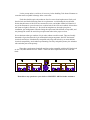
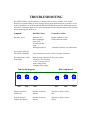
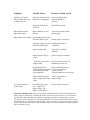
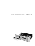
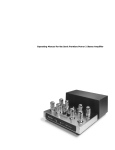
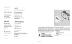
MANLEY
LABORATORIES, INC.
OWNER'S MANUAL
MANLEY STEELHEAD
MM/MC GRAMOPHONE CARTRIDGE PREAMPLIFIER
MANLEY LABORATORIES, INC
13880 MAGNOLIA AVE.
CHINO, CA. 91710
TEL: (909) 627-4256
FAX: (909) 628-2482
[email protected]
http://www.manleylabs.com
CONTENTS
SECTION
PAGE
INTRODUCTION
3
INSTALLATION PRECAUTIONS
4
FEATURES AND APPLICATIONS
5
OPERATIONAL NOTES
9
TROUBLESHOOTING
12
SPECIFICATIONS
14
WARRANTY
15
WARRANTY REGISTRATION
16
INTRODUCTION
THANK YOU!...
...for choosing The MANLEY STEELHEAD phono preamplifier. Please read over this
manual carefully as it contains information essential to the proper operation and maximum
enjoyment of this instrument.
The MANLEY STEELHEAD is designed to provide that rare combination of maximized
sonic performance coupled with a generous ability to adapt to any moving magnet, moving coil or
iron vane phono cartridge you may wish to use. With the STEELHEAD’s feature compliment,
you no longer have to settle for what a given cartridge sounds like with a fixed predetermined
preamp load impedance, or wonder what that same cartridge might sound like when presented
with different loading arrangements. What best suits your particular phono cartridge, system,
listening room and personal preference is now merely a flick of a switch away! The
STEELHEAD adapts to accommodate your situation, rather then the other way ‘round.
To this end you will notice that it is the anticipation of your preamplifier needs which has
driven every detail of the STEELHEAD’s planning, engineering, styling, operating convenience
and adaptability.
UNPACKING
Unpack the preamplifier carefully and make sure that all supplied accessories are present.
Examine all items for any possibility of shipping damage. All six tubes should be standing at
attention in their sockets. If the preamplifier is damaged or fails to operate, notify the shipper and
your dealer or us immediately. Or if the preamp was shipped to you directly, notify the shipping
company without delay.
Your STEELHEAD preamp was packed with the following accessories:
a)
b)
c)
1 each Power supply unit with interconnect cable.
1 each 6 foot IEC 3-conductor power cable.
1 each Owner’s manual.
It is prudent to retain the shipping materials for future use, as these materials are
custom formed for the preamp and will greatly minimize the chance of shipping-related
damage.
INSTALLATION PRECAUTIONS
a)
Avoid locating the preamp where it will be exposed to direct sunlight, excessive humidity, dust or moisture.
Extreme environments may temporarily or permanently degrade preamp performance.
b)
Keep the preamp housing away from sources of strong magnetic field radiation, such as large video display
CRTs, large power lines or power/audio transformers in nearby equipment. Extra measures have been taken to
shield the magnetically sensitive bits inside the preamp housing. Nevertheless these measures can be
overwhelmed by strong outside influences. Keep in mind that the tiniest disturbance along with the desired
signals will be amplified many hundreds or thousands of times.
c)
Locate the preamp away from heat-radiating sources, such as other large amps, political demagogues or
space-heating equipment.
d)
Make sure the preamp and power supply is off before making any system connections. Do not remove or
insert the large 16-pin circular power supply connector when the power supply mains switch is in the on (|)
position. Do not hot plug the system.
e)
Dissipate any static electric charge build-up on your body by touching the enclosure before making or
changing any system connections. The preamp electronics are fairly robust as far as immunity to damage from
static charge is concerned, but total immunity cannot be had without unacceptable compromise of audio
performance.
f)
Be careful to feed only low-level phono cartridge signals to the preamp input connectors. Sustained line-level
signals above 15 volts peak may cause damage to sensitive MC input stages even when the preamp is in the
standby mode or when the power is off.
AC VOLTAGE SELECTION
The STEELHEAD system may be set to operate on either 117 or 234 volts A.C. by means of a rotary switch
located on the power supply P.C. board. The power supply's mains-voltage selector switch is normally preset to the
mains voltage at the customer's location prior to shipment. If, however, the preamp provenance is unknown then the
mains-voltage selector switch should be checked and reset to the correct voltage if necessary. The mains fuses must
also be checked for proper ratings and changed if necessary. Failure to correctly set the mains selector switch or use
properly rated fuses can cause extensive damage to the system which is of course not covered by the warranty.
The mains fuse may be checked by first disconnecting the IEC mains cord from the power supply’s power inlet plug.
Then gently press the small leaf spring on the side of the rectangular gray fuse retainer cap. The fuse and cap should
spring outward toward your fingers. Inspect the fuse for the proper rating; change if necessary. Refer to the fuse-rating
chart in the specifications section of this manual.
To inspect or adjust the mains-voltage selector switch it will be necessary to remove the top cover of the
power supply enclosure. For this you will need a #1 Philips screwdriver, and a 3/16 inch flat blade driver to change
the selector switch setting.
Before opening make sure that the power supply is unplugged from mains power and the STEELHEAD
preamp. Once inside you will see tall cylindrical high voltage energy-storage capacitors, which can be a shock
nuisance even when the supply is not energized. Therefore, if the supply has been recently power cycled, let the
supply capacitors discharge for 15 minutes prior to opening. Then remove 8 Philips 4x40 retaining screws from the
cover, followed by the cover. Locate the voltage selector switch near the mains power entry / fuse / power switch
module. The switch face is the black round object, about 1/2 inch in diameter, with white voltage numbers “110” and
“220” on the rotor and a white triangular selection indicator on the stator. Notice that the “110” and “220” markings
on the switch should not be interpreted as being the precise voltage needed to operate the preamp system. Using the 3/
16 inch screwdriver rotate the switch, if necessary, so that the mains voltage you intend to feed the power supply lines
up under the selection indicator. Be sure to replace all screws when reassembling.
FEATURES AND APPLICATIONS
1.
HIGH PERFORMANCE FRONT END
The STEELHEAD preamplifier makes the best use of active and passive component and
circuit developments generated over the past half-century. The hybrid cascode gain blocks
simultaneously deliver wide-band high-gain, low noise and low distortion performance without
having to resort to heavy-handed amounts of negative feedback. Or overly complex circuit
topology. The multiplicative aspect of the cascoded device’s output (anode) impedance means that
the most important characteristics of each gain stage are preserved even though the local negative
feedback present in each block is very small. This approach makes the amplification factor of each
stage insensitive to tube gain or transconductance variations which occur due to device production
tolerance allowances or aging.
Other uncommon traits include high quiescent and operating current in each gain stage. This
lowers the static and dynamic impedances found within each stage and raises system bandwidth.
Musical material which would cause a cave-in of the typical current-starved 12AX7-based
preamplifier circuit are conveyed unflinchingly by these amplifier stages.
2.
ACCURATE “4-CORNER” RIAA EQUALIZATION
In the spirit of high fidelity, all four RIAA phono equalization corner frequencies or time
constants have been specifically addressed in the STEELHEAD preamplifier. Historically most
designs have concentrated on the “big three” time constants of 3180, 318 and 75 microseconds.
This ignores the fourth corner of about 3.2 us, which when ignored causes most phono stages to
continue rolling off the highest octave signals coming from the phono pickup, rather than turning
the final “corner” and shelving to flat response at about 50 kHz. Careless removal of upper octave
bandwidth causes the recovered audio to become somewhat lifeless and remote, with needless loss
of impact, detail and percussiveness. Ironically this signal content is precisely what is omitted from
all currently popular digital audio delivery formats, and is one of the chief culprits behind the
homogenous upper octave sonic characteristics of those formats.
As with all equalizing amplifiers intended to correct a given form of frequency-selective
emphasis curve, care must be used when building the restorative compensation networks. Great
care must be exercised if the goal is to produce a highly accurate passive network coupled to lowfeedback amplifiers. And experience has shown that the effort spent in faithfully adhering to the
inverse RIAA equalization curve produces results that easily justify the additional procurement and
manufacturing costs. To this end, only hand-selected and/or1% tolerance components are used
throughout the RIAA equalization network. Add to that the factory-set variable capacitors, and the
result is very high equalization accuracy where small component and circuit layout variations that
other manufacturers ignore are netted out. This yields impeccable inter-channel phase and gain
matching at any gain setting. In short, the STEELHEAD will magnify the differences in the
character and personality of your vinyl recording collection, cartridge, tonearm and turntable. A
microscope for the ear! Be prepared to hear previously undiscovered musical content as you play
back your favorites!
3.
SWITCH-SELECTABLE CARTRIDGE LOAD IMPEDANCE
An effective means of varying the load seen by the MC cartridge has been included in the
form of a 5-position rotary switch. This switch selects various taps on a specially manufactured
dual-primary bi-filar wound, high-bandwidth low-resistance and multiple-shielded nickel-core
step-up autoformer. A drama to make, the autoformer permits the minute MC cartridge signal
power to be efficiently and transparently transformed from low-volts/high-current to high-volts/
low-current. By avoiding conventional parasitic cartridge termination resistors, none of the MC
cartridge’s tiny signal power is thrown away before amplification. This results in improved system
signal-to-noise ratio. Quite worthwhile provided, as in the STEELHEAD, the autoformer has the
necessary performance for the job. This pivotal component has had engineering attention lavished
upon it in the only way possible or practical: The Manley Labs magnetics department. In-house
transformer prototyping and manufacturing capabilities permit realization of extraordinary
transformer designs.
You may now audition your MC cartridge at or near the manufacturer’s specified loading
resistance without sacrificing any signal power through a parasitic load resistor. And explore the
interesting tonal shifts caused by intentional mild or severe mis-termination of the cartridge. The
“right” setting will ultimately depend on the cartridge in use, type of music being heard, other
downstream equipment and, most importantly, your personal preference. There will no doubt be
moments when a technically “wrong” setting will be musically “right” for a given situation. Do
rest assured that, in this instance, a technically wrong setting is completely harmless for all
equipment involved.
In the case of the MM input, the typically higher cartridge output levels allow fixed resistor
termination, with clockwise-most switch setting being the standard 47k-ohm load resistance. Those
MM cartridges capable of properly driving low impedance loads between 25 and 400 ohms should
be auditioned through both the MM and MC inputs. By doing so you may find the most
appropriate sonic character through the use of unconventional input arrangements. In short,
experiment; don’t let the control labeling stop you. On the contrary, we invite you to tweak away!
4.
SWITCH-SELECTABLE CARTRIDGE TERMINATION CAPACITANCE on the
front panel yet!
Termination capacitance may be applied to each channel independently in 10 pF steps, up to
1100 pico-Farads. The termination capacitance is present at the gain-stage inputs, and is not affected
by input selector or gain switch changes. For best accuracy consult your phono interconnect cable
literature or manufacturer to determine how much of the termination capacitance may be attributed to
the cable. Then subtract at least that amount from the target capacitive termination value.
If the interconnect manufacturer does not know the amount of capacitance per unit length that
their wire presents (!), then refer to the following example for a starting point: Typical phono
interconnect cables will exhibit self-capacitance on the order of about 30 pF per foot. If the
interconnect cable is 3 feet (~ 1 meter) in length, you may expect about 90-100 pF of input
capacitance to be present due to the interconnect cable alone. If the cartridge manufacturer specifies a
load capacitance of 150 pF then it is best to subtract the cable’s portion, i.e. 90 pF. This yields a
balance of 40 pF. Thus, the audition should start with the termination capacitance switches set to 40
pF.
Each cartridge manufacturer’s product will work best in a laboratory sense when
terminated (loaded) with a certain amount of resistance and capacitance. By lab sense it is meant
that the signal developed by the cartridge is at maximum power transfer into the pre-amp, with
minimum overshoot and ringing, flattest frequency response and gentle roll-off characteristics. But
it is those settings that create the most musically satisfying results for you that are of uppermost
importance. And your termination preferences may rightly deviate unpredictably from some labbased norm. A good place to start is with those values recommended by the cartridge
manufacturer, less the interconnect cable capacitance. A good default value, if the recommended
cartridge load capacitance is unknown, is 150 pF, the sum of cable and termination capacitance
switch settings. This value reflects a de facto standard as used by pre-amp manufacturers past and
present. From there we encourage you to scrutinize a range of switch settings until you find those
values which best suit you and your accompanying components.
Also notice that the audible affects of varying the termination capacitance can differ
substantially between cartridge types and brands. This is to be expected due to the greatly varying
source impedance characteristics of the cartridges available today. In general you may expect the
termination capacitance value to alter, at one extreme, subtle imaging and spatial cues, and at the
other high-frequency content, forwardness and speed of the reproduced sound. As with the load Z
switch, feel free to tune the termination capacitance switches for maximum sonic satisfaction even
though the final setting differs from the cartridge manufacturer’s specs.
5.
SWITCH-SELECTABLE AMPLIFIER GAIN
Cartridge output levels and downstream line-level interconnect drive voltage requirements
can vary greatly between manufacturers. Hence a four-step amplifier-block gain control has been
included to accommodate these differences, as well as differing cartridge sensitivities. You may
select from 50 to 65 dB of gain in 5 dB steps. The gain figure is referred to amplifier gain at 1
kHz. Notice that the pre-amp gain is about 20 dB higher (10 times) at 20 Hz and about 20 dB
lower (0.1 times) at 20,000 Hz. The MC step-up autoformer may also provide approximately 2 to
12 dB of additional voltage gain depending on cartridge source impedance and load switch setting.
6.
PUSH-BUTTON SWITCH FUNCTIONS
Four feature switches have been provided for a variety of utility functions.
STANDBY toggles the STEELHEAD between normal operating state and a near zeropower sleep mode. No operating voltages are present when in sleep mode, except for some keepalive CMOS system control logic, energized by a separate small mains transformer in the power
supply.
SUM combines the amplified audio into a binaural signal, present at the VARIable outputs
only. Monophonic or the lateral-only modulation content of your stereo records may now be
heard. True mono may be experienced if the feed to one of your two loudspeakers is cut.
DIM reduces the output level by 20 dB, or about 1/4 previous volume. The DIM function is
effective at the VARIable outputs only. Notice that preamp specifications at the VARIable output
may be slightly compromised with the DIM feature engaged. This feature should be treated as a
convenience for use when, for example, cueing up a record. System-menacing pops and thumps
due to needle-drop are held at bay yet sound from the pick-up may still be heard.
MUTE kills audio signals present at both the FIXED and VARIABLE outputs.
7.
BUFFERED VOLUME CONTROL
The STEELHEAD is equipped to drive external power amplifiers directly via low output
impedance VARIable line drivers. Purists may easily bypass other outboard preamplifier circuitry
by connecting power amplifier inputs directly to the STEELHEAD’s VARIable output jacks.
8.
SEPARATE BUFFERED FIXED AND VARIABLE OUTPUTS
Choice of constant-level source for interconnection to a line-level-only preamp or recorder,
and variable outputs for direct connection to power amplifiers.
9.
DISCRETE CIRCUIT AND CHASSIS GROUND POINTS
Breakable link between electronics common “zero volts” point and chassis ground allows
great flexibility in grounding arrangements.
10.
REMOTE HIGH PERFORMANCE POWER SUPPLY
Multiple channel power supply in separate enclosure eliminates supply proximity-based noise
intrusions into the signal path. Robust and regulated ultra quiet high-voltage rail maintains
electrical quiet for sensitive gain input stages. Each voltage channel is conveyed to the preamplifier
via separate source and sink lines; no common supply points except at the star-grounding point on
the amplifier boards. Multi-core interconnect cable is screened via tinned overall shield braid.
OPERATIONAL NOTES
VOLUME
INPUT
GAIN dB
MC LOAD Z, ohms
LOAD
CAP,
pF
x 100
3
2
1
0
4
5
6
3
7
8
9
10
2
1
0
100
100
x 10
4
5
3
7
8
MMMC
LOAD
CAP,
pF
x 100
6
MC MM
2
4
5
6
x 10
3
7
8
9
1
9
10
0
10
2
1
0
4
5
6
7
8
9
10
PREPARATION FOR INSTALLATION
Budget a suitable space in which to place the preamplifier, power supply and associated
interconnect cable. This space should be free of strong external magnetic and RF fields, and
reasonably removed from strong loudspeaker-generated acoustical fields. This space should also
be free of excessive heat or dust and large enough to permit easy flow of cool air to the top, bottom
and sides of the preamp and power supply.
Make sure the power supply’s mains voltage selector switch is set to match the local line
voltage, and the wire link is present between the preamp’s green CHASSIS and black CIRCUIT
ground mini binding posts on the rear panel.
Try to position the power supply away from any interconnect cables which may be carrying
audio signals.
BEFORE POWER-UP
Once placed, join the power supply cable to the pre-amplifier via the large16-pin circular
connector. The 16-pin connectors are keyed and can only be mated when both halves are lined up
correctly. Check and make sure the power supply is switched off, then attach the grounded IEC
power cable jack to the IEC plug. Keep the power off until all other system connections are
completed.
Proceed by connecting the input and output cabling to the signal sources and loads as
desired. Tie any separate turntable or tonearm ground lead to the gold CHASSIS ground binding
Set the GAIN dB control to 55 dB and VOLUME control to about 9 o’clock. Choose the
MM or an MC input, as necessary, with the INPUT control. Place the LOAD Z switch to a value
at or near that recommended by the cartridge manufacturer. Adjust the LOAD CAP switches to a
value at or near that recommended by the cartridge manufacturer less any interconnect cable
capacitance. Select and clean, if necessary, your favorite gramophone record....
Plug the power cable in and place the power supply’s mains power switch in the on (|)
position. The STANDBY switch should glow. Push the STANDBY switch. The STANDBY
switch will go dark, selected INPUT and GAIN blue LED’s will illuminate, the MUTE switch
lamp will start flashing and the power supply pilot LED and the MANLEY STEELHEAD badge
will light up.
The winking MUTE lamp indicates the beginning of a 30 second warm-up mute delay,
during which time the muting relay is engaged; no output will be heard from the preamp.
DURING OPERATION
Once audio is heard from the STEELHEAD the exploration for the ideal control settings can
begin. However it would be best to allow about 15 minutes of warm-up time for the system to
reach thermal equilibrium.
Again, notice that the MUTE function operates over both FIXED and VARIable outputs,
while the DIM and SUM functions are only available at the VARIable output jacks.
RETURNING TO STANDBY MODE
At the conclusion of your listening session press the STANDBY switch again to cut power
to the preamp. Notice that effort has been made to keep power engagement and cessation noise
generated by the preamp to a minimum. Nevertheless it is wise to remove power mains and signal
feed to your power amps when the preamp is undergoing a power state change.
Additionally, it is best to return the STEELHEAD to the STANDBY mode when not in use
rather then leaving the power on indefinitely. This will enhance tube and system life. The tubes
should last thousands of hours under normal conditions.
REPLACING A TUBE OR ILLUMINATED BADGE LAMP
Yes there are user-servicable parts inside! But, as with other vacuum tube based products,
there is also high voltage present. Therefore caution must be used when covers are removed;
otherwise there could be shock hazard. As with all mains-powered gear make sure the mains power
is off and mains cords are unplugged. Then unplug the power supply from the preamp. If the
preamp has been powered up within the last 15 minutes stop! and let the large internal capacitors
finish discharging. Wait about 5 minutes before opening the preamp once the 16-pin connector is
unplugged.
You will need a #1 Philips screwdriver and a small slot driver.
FUSE-LAMP REPLACEMENT: After removing the cover use the small slot driver to help
pry the badge’s fuse-lamp out of the clip holder. Use one hand only when reaching into the
enclosure or touching any components inside. Keep the other hand away from the preamp,
preferably in your pocket.
TUBE REPLACEMENT: Increased noise level whether gradual or abrupt can generally be
attributed to aging tubes. Gradual noise increase from weakened tube cathode emission is the chief
symptom of an aging tube, which may be accompanied by exaggerated distortion or loss of
headroom. The noise may be a variation in the level of hiss, or the noise may develop a more
granular “large-curd” quality. Should these symptoms appear, unplug the tubes in the offending
channel and replace with new devices of known-good quality. If the front-end 6922 tube is being
replaced in one channel it is wise to replace the same tube in the alternate channel, preferably with
matching manufacturer and date code if possible.
Let the preamp tube(s) cool down, if necessary, before handling. Tube heater filaments are
somewhat more suceptable to damage when warm or hot.
Each tube should require only moderate force for removal and replacement. Gently rock
the tube back and forth a bit during removal or replacement. Avoid bending the circuit board.
Notice that the heaters of the 6922s are connected in series, and neither channel will function if
one of the filaments is open or burned out, or unless both of the 6922s are installed. Akin to those
old Xmas tree lights in the attic, no? Be careful to straighten any bent tube pins prior to
installation; pin misalignment will make fitting the replacement tube difficult or impossible, and
may damage the socket. Be careful to put replacement tubes in the proper sockets.
Never substitute other type numbers of 9-pin tubes without careful research. There are literally
thousands of types that share the 9-pin mechanical basing arrangement, but NOT the internal
electrical connections! Mechanically compatible tube plugs and sockets by no means indicate
electrical compatibility! And random experimenting can easily and quickly destroy the substitute
tube and other parts of the preamp!
Three tube types that are electrically and plug-socket compatible with the 6922 dual triode
are the 7308, 6DJ8 and the ECC88 / E88CC. There is no direct replacement for the 7044 dual
triode.
MC-2
RIGHT OUTPUTS
GROUND
RIGHT INPUTS
LEFT INPUTS
CHASSIS
LEFT OUTPUTS
CHASSIS
VARI
FIXED
MM
MC-1
MC-1
MM
FIXED
VARI
CIRCUIT
Please direct any questions to your dealer or MANLEY LABS for further assistance.
TROUBLESHOOTING
The STEELHEAD’s system architecture is designed with a variety of features so as to allow
flexibility in accommodating as many cartridges and as much downstream gear as possible. Access
to these capabilities rest on the assumption that all STEELHEAD systems are functioning properly.
If trouble is encountered please review the following short list of symptoms and corrective remedies
before contacting your dealer or us.
Symptom
Possible Cause
Corrective Action
NO lights, power.
Bad mains fuse.
Bad or unplugged
power cable.
AC outlet not energized.
Rolling Grayout®™
Replace with correct fuse.
Check cables and outlets.
Power supply pilot ON,
‘HEAD not responding.
Dim badge lamps, LEDs.
Weak output.
Abandon California, elect Libertarians.
16-pin connector not seated. Check for proper connection.
Mains Voltage selectorCheck for proper setting.
switch set to 220 V instead
of 110 V. Be sure of local
mains voltage before
changing switch setting!
Tube locator diagram
7044
7044
6922
RIAA amp board
6922
7044
Output heard in one
channel only.
Bad tube in affected
channel.
Alternate or replace suspect
tube.
Weak or distorted
output in one channel.
Bad tube in affected
channel.
Alternate or replace suspect
tube(s).
7044
Symptom
Possible Cause
Lights ON, no output
either channel after warm
up delay times out.
Open 6922 filament, either
channel. 6922 unplugged.
Check for glowing 6922
filaments. Replace if
necessary.
Output MUTE function
activated.
UnMUTE the preamp.
Input connectors are nonshorting.
Avoid unused inputs; install
shorting plugs.
Hum heard on unused
MM or MC inputs.
Corrective Action, cont’d
Hum heard on active inputs. Ground link between CHASSYS and CIRCUIT open.
Replace jumper if necessary
Turntable / tonearm ground Establish inter-chassis
link to CHASSIS open.
connection.
Open cartridge leads.
Check lead / head-shell
continuity.
Phono plugs not fully inserted.
Check for proper connection.
‘Table lines close to hum
magnetic field.
Keep source lines away from
transformers, motors, etc.
Ground loop between
STEELHEAD and turntable
or downstream pre-amp/
power amplifiers.
Break ground connection of
one or two of the three
system elements.
Experimentation may be necessary.
Faulty shield connection,
Roll or swap cables, or
input or output interconnect replace cables.
cables.
No or bad sound heard
on MC2 input.
Check DIN plug wiring
Left: 1high, 4 low.
Right: 3 high, 5 low,
Shield: 2 earth, chassis.
Re-wire plug for continuity.
Remarks on hum pick-up: Please be aware that the STEELHEAD can develop voltage amplification
factors as high as 30,000 times, or 90 dB at the 50-60 Hz power line “hum” frequencies. It is of the utmost
importance that cables handling the tiny signals from the phono cartridges be of high quality, with good
screening and connection properties, if the single-ended signal is to have any chance of being received by the
preamp reasonably free from hum and noise intrusions. This is especially true formoving coil pickups. Please
use the shortest practical interconnects and carefully route these away from all possible electrical or magnetic
hum or interference sources.
SPECIFICATIONS
Vacuum tube compliment: 6922 x 2 (gain) plus 7044 x 4 (output buffers)
Fuse type and ratings:
117 VAC: 1.5 Amp 3AG slow-blow main
0.5 Amp 3AG slow-blow logic
234 VAC: 0.75 Amp 3AG slow-blow main
0.25 Amp 3AG slow-blow logic
Moving Magnet input impedance:
5-step user adjustable via fixed low-noise resistors.
25, 50, 100, 200 and 47000 ohms.
Moving Coil input impedance:
5-step user adjustable via multi-tap autoformer:
25, 50, 100, 200 and 400 ohms.
Input Termination Capacitance:
Variable in 10 picofarad steps from 10 to 1100 pF.
(1.1 nF). Residual input capacitance less than 40 pF.
Gain Steps: 4-step user adjustable, 50, 55, 60 and 65 dB active gain at 1 kHz referred to FIXED
output jack, 10 k-ohm load. Additional gain available via MC step-up autoformer.
Deviation from RIAA curve: Less than +0.5 / -0.3 dB from 20 Hz to 20 kHz, any gain setting.
Typically less than +/- 1 dB from 10 Hz to 100 kHz
Inter-channel differential phase: Less than 4 degrees from 20 Hz to 20 kHz, any gain setting.
Typically less than 2 degrees.
Inter-channel differential gain: Less than +/- 0.5 dB from 20 Hz to 20 kHz, any gain setting.
Dynamic Range:
101 dB @ 1 kHz, 1% THD
200 ohm source, 47 k-ohm input, @55dB Gain
97 dB @ 1 kHz, 0.1% THD
Maximum Output:
+27dBm @ 1KHz with 3% THD into 100Kohm load
FIXed Output impedance:
150 ohms. Minimum suggested load greater than 1500 ohms.
VARIable Output impedance:
75 ohms. Minimum suggested load greater than 600 ohms.
MM Noise (S+N+D) / (N+D):
200 ohm source, 47 k-ohm input
A-weighted Referred to 2.54 mV
rms @ 1 kHz.
GAIN setting
50 dB:
55 dB:
60 dB:
65 dB:
MC Noise (S+N+D) / (N+D):
100 ohm source, 100 ohm input
A-weighted Referred to 0.5 mV
rms@ 1KHz and rated input impedance
50 dB:
55 dB:
60 dB:
60 dB:
Fixed Ouptut
Vari O/P
86 dB
108dB 99dB 86dB
84 dB
108dB 99dB 85dB
80 dB
108dB 94dB 80dB
75 dB
108dB 89dB 75dB
9:00 12:00 V/C FULL
84 dB
108dB 98dB 85dB
80 dB
108dB 95dB 81dB
75 dB
108dB 90dB 76dB
70 dB
107dB 85dB 71dB
WARRANTY
All Manley Laboratories equipment is covered by a limited warranty against defects in
materials and workmanship for a period of 90 days from date of purchase to the original
purchaser only. A further optional limited 5 year warranty is available to the original purchaser
upon proper registration of ownership within 30 days of date of first purchase.
Proper registration is made by filling out and returning to the factory the warranty card
attached to this general warranty statement, along with a copy of the original sales receipt as
proof of the original date of purchase. Only 1 card is issued with each unit, and the serial
number is already recorded on it.
If the warranty registration card has already been removed then this is not a new unit, and is
therefore not warranted by the factory. If you believe this to be a new unit then please contact
the factory with the details of purchase.
This warranty is provided by the dealer where the unit was purchased, and by Manley
Laboratories, Inc. Under the terms of the warranty defective parts will be repaired or replaced
without charge, excepting the cost of tubes. No warranty is offered on tubes, unless:
1. a Manley Laboratories preamplifier is used with a Manley Laboratories amplifier, and
2. the warranty registration card is filled out.
In such a case a 6 month warranty on tubes is available with the correct recording of the serial
number of the preamplifier on your warranty registration card.
If a Manley Laboratories product fails to meet the above warranty, then the purchaser's sole
remedy shall be to return the product to Manley Laboratories, where the defect will be repaired
without charge for parts and labour. The product will then be returned via prepaid, insured
freight, method and carrier to be determined solely by Manley Laboratories. All returns to the
factory must be in the original packing, (new packing will be supplied for no charge if needed),
accompanied by a written description of the defect, and must be shipped to Manley
Laboratories via insured freight at the customer's own expense. Charges for unauthorized
service and transportation costs are not reimbursable under this warranty, and all warrantees,
express or implied, become null and void where the product has been damaged by misuse,
accident, neglect, modification, tampering or unauthorized alteration by anyone other than
Manley Laboratories.
The warrantor assumes no liability for property damage or any other incidental or
consequental damage whatsoever which may result from failure of this product. Any and all
warrantees of merchantability and fitness implied by law are limited to the duration of the
expressed warranty. All warrantees apply only to Manley Laboratories products purchased and
used in the USA.
Some states do not allow limitations on how long an implied warranty lasts, so the above
limitations may not apply to you. Some states do not allow the exclusion or limitation of
incidental or consequential damges, so the above exclusion may not apply to you.
This warranty gives you specific legal rights and you may also have other rights which vary
from state to state.
WARRANTY REGISTRATION
We ask that you please fill out this registration form and send the bottom half to:
MANLEY LABORATORIES
REGISTRATION DEPARTMENT
13880 MAGNOLIA AVE.
CHINO CA, 91710
or FAX it
(909) 628-2482
or email
[email protected]
with all the info requested below and
a note stating this is Warrantee Registration.
Registration entitles you to product support, full warranty benefits, and notice of product
enhancements and upgrades. You MUST complete and return the following to validate
your warranty and registration. Thank you again for choosing Manley Laboratories.
MODEL _______________SERIALNo.______________________
PURCHASE DATE __________ SUPPLIER __________________
--------------------------------------------------------------------------------------------PLEASE DETACH THIS PORTION AND SEND IT TO MANLEY LABORATORIES
MODEL _________________SERIAL No. __________________
PURCHASE DATE ________ SUPPLIER ___________________
NAME OF OWNER____________________________________________
ADDRESS___________________________________________________
CITY, STATE, ZIP _____________________________________________
TELEPHONE NUMBER ________________________________________
FAX _________________________________________________________
EMAIL______________________________________________________
COMMENTS?_________________________________________________