1
Pin Assignments
5.3.1
SCON Header (J7)
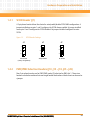
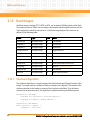
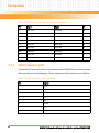
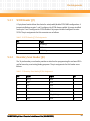
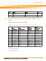
A 3-pin planar header allows the choice for auto/enable/disable SCON VME configuration. A
jumper installed across pins 1 and 2 configures for SCON always enabled. A jumper installed
across pins 2 and 3 configures for SCON disabled. No jumper installed configures for auto
SCON. The pin assignments for this connector are as follows:
Table 5-16 SCON Header (J7) Pin Assignments
5.3.2
Pin
Signal
1
SCONEN_L
2
GND
3
SCONDIS_L
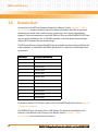
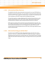
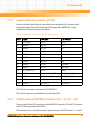
Boundary Scan Header (J8)
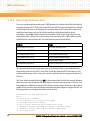
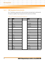
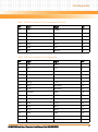
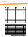
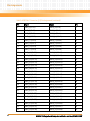
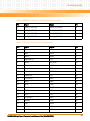
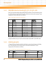
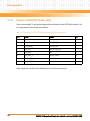
The 14-pin boundary scan header provides an interface for programming the on-board PLDs
and for boundary scan testing/debug purposes. The pin assignments for this header are as
follows:
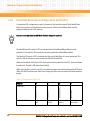
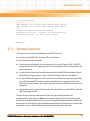
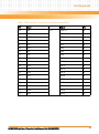
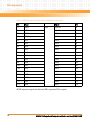
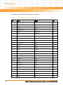
Table 5-17 Boundary Scan Header (J8) Pin Assignments
Pin
Signal
Signal
Pin
1
TRST_L
GND
2
3
TDO
GND
4
5
TDI
GND
6
7
TMS
GND
8
9
TCLK
GND
10
11
NC
CPU_BSCAN_L
12
13
AW_L
GND
14
MVME6100 Single Board Computer Installation and Use (6806800D58E)
97