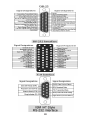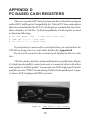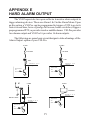
1
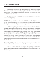
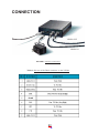
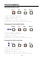
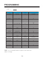
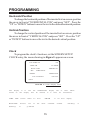
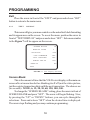
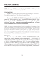
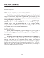
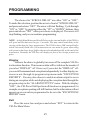
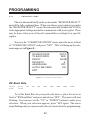
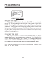
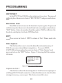
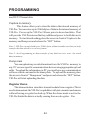
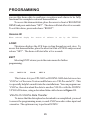
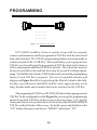
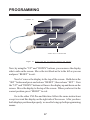
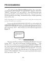
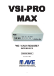
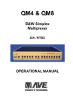
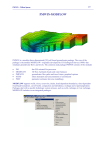
VSI-Pro Cash Register Interface Operation Manual Version 12.00 1 VSI-Pro IS YEAR 2000 FCC CE COMPLIANT CAUTION! RISK OF ELECTRICAL SHOCK! DO NOT OPEN! CAUTION! TO PREVENT ELECTRIC SHOCK, DO NOT REMOVE COVER. NO USER SERVICEABLE PARTS INSIDE. REFER SERVICING TO QUALIFIED PERSONNEL. WARNING: TO PREVENT FIRE OR ELECTRIC SHOCK, DO NOT EXPOSE THIS APPLIANCE TO RAIN OR MOISTURE! WARNING! THIS EQUIPMENT GENERATES, USES, AND CAN RADIATE RADIO FREQUENCY AND IF NOT INSTALLED AND USED IN ACCORDANCE WITH THE INSTRUCTIONS MANUAL, MAY CAUSE INTERFERENCE TO RADIO COMMUNICATIONS. IT HAS BEEN TESTED AND FOUND TO COMPLY WITH THE LIMITS FOR A CLASS A COMPUTING DEVICE PURSUANT TO SUBPART J OF PART 15 FCC RULES, WHICH ARE DESIGNED TO PROVIDE REASONABLE PROTECTION AGAINST SUCH INTERFERENCE WHEN OPERATED IN A COMMERCIAL ENVIRONMENT. OPERATION OF THIS EQUIPMENT IN A RESIDENTIAL AREA IS LIKELY TO CAUSE INTERFERENCE IN WHICH CASE THE USER AT HIS OWN EXPENSE WILL BE REQUIRED TO TAKE WHATEVER MEASURES MAY BE REQUIRED TO CORRECT THE INTERFERENCE. Copyright (C) 2002 AVE Thailand Co., Ltd. 2 CONTENTS 1. INTRODUCTION ..................................................................... 4 2. FEATURES ................................................................................ 5 3. CONNECTION ......................................................................... 6 4. PROGRAMMING..................................................................... 9 4.1 FRONT CONTROL PANEL .................................................. 9 4.2 GETTING STARTED ........................................................... 1 1 4.3 MAIN PROGRAMMING MENU ........................................ 1 1 4.3.1 REGISTER SELECT ................................................... 1 2 4.3.2 SCREEN SETUP .......................................................... 1 4 4.3.3 TEXT DISPLAY ........................................................... 1 8 4.3.4 COMMUNICATION .................................................... 2 2 4.3.5 EXCEPTION REPORTS ............................................. 2 5 4.3.6 ALARM OUTPUTS / INPUT ...................................... 3 6 4.3.7 TEST/DEMO MODE ................................................... 4 1 4.3.8 DOWN/UP LOAD SETUP .......................................... 4 5 4.3.9 HELP ............................................................................. 4 9 APPENDIX A - Problem Solving ................................................ 5 0 APPENDIX B - Triports / Adapters / Cables ............................ 54 APPENDIX C - PinOuts .............................................................. 6 7 APPENDIX D - PC Based Cash Registers ............................... 71 APPENDIX E - Hard Alarms ..................................................... 73 APPENDIX F - Master Reset .................................................... 76 Warranty ...................................................................................... 7 7 Exception Record ........................................................................ 7 9 Index ............................................................................................. 8 0 3 1. INTRODUCTION The Video Serial Interface (VSI-Pro) allows characters to be inserted into any video source via an RS-232 link. This allows computers, cash registers, ATM's and any RS-232 communicating device to display alphanumerics in the video picture of a CCTV system. Simple front panel push-buttons allow the user to interactively on-screen program this powerful device. Whether used with a cash register providing real time data on a RS-232 port or tapping off a serial printer, the VSI-Pro is a valuable tool in loss prevention. When used in conjunction with other AVE interface devices like the Parallel to Serial converter (P2RS), the VSI-Pro can be connected to any computer printer port for a video display of what the printer is outputting. Additional interface modules convert for many other standard and nonstandard communication formats. Consult the AVE catalog or visit www.americanvideoequipment. com to choose the proper interface to meet your need. The VSI-Pro via its powerful internal processing of exceptions actually intelligently monitors the data stream coming from the cash register and alerts the user to “exceptional” or out of the ordinary transactions. The VSI-Pro then can be used to trigger switchers, Time Lapse VCR's or other alarming devices to mark these events for future or instantaneous review. The auxillary RS-232 output port of the VSI-Pro can be used to send serial data to modems, logging PCs and PTZ controllers to do any desired function. Multiple alarm outputs and alarm inputs allow triggers from and to other equipment. The internal on-screen Time & Date automatically locks to most incoming data streams that include this information. This allows the Time & Date of the CCTV system to synchronized to the POS or ATM system to give legal evidence. 4 2. FEATURES • 45 Different Cash Register Selections. • Easy On-screen Menu driven Setup and Programming. • 24 Field Programmable Exceptions with Numeric Range. • Programmable Time-Stamp on Exception Output. • Universal or American Time/Date format. • 100 lines Exception History Buffer. • 16 Triggered Text associated with 16 alarms. • 2 built-in Programmable Alarm Outputs. • Alarm Input for Drawer Open, Safe Open, etc. • Serial Output of all data or Exceptions to Printers, Computers, or Modems • Powerful Data Filtering Algorithms. • Larger data buffers for input/output to accommodate newer, faster registers. • Auto Baud Rate Detection. • On-screen Flagging of Exceptions with Asterisk or Reverse text. • Programmable Delay Screen Blanking. • Choice of 1 to 9 lines displayed on-screen. • On-screen Titler up to 20 Characters and up to 10 Character sizes. • Gray Scale and Border Selection from front panel • Built-in Test Mode • Built-in Cash Register Demo • Upload/Download Programming to a PC or another VSI-Pro • Data dumped either to the memory or to the port 5 3. CONNECTION The VSI-Pro will overlay the characters on any input video source. The video input can be virtually any base band or composite video source. The VSI-Pro will accept NTSC, RS-170, RS-330, CCIR, PAL or SECAM video formats. The Video input to the VSI-Pro is a standard BNC connector, terminated at 75 [ohms]. NOTE: The input video level must be 1[V] Peak to Peak. If this level is not maintained within +/- 20%, the VSI-Pro will have difficulty locking the character display over the input video source. After completing the interface installation as described in the separate Installation Guide for your specific Cash Register, Computer, Radar Gun or other serial device. Connect the video input source to the video input BNC on the rear of the VSI-Pro. The BNC video output goes out to the video system (VCR, Quad, switcher, Multiplexer, or monitor). This connection is shown in figure 1. The video output from the VSI-Pro is 1[V] Peak to Peak into a 75 [ohm] load. Most monitors or televisions with direct video inputs are terminated with a 75 ohm load. If the monitor is not terminated, the VSI-Pro will still output 1[V] Peak to Peak. Note: The VSI-Pro will not enter the programming mode unless it is connected to a video source. Included with the VSI-Pro is a 9 [V] DC @300 [mA] UL/CSA power supply which must be plugged into the POWER Input on the VSIPro’s real panel. 6 CONNECTION VIDEO OUT VIDEO IN FIGURE 1: VSI-Pro Connections Table 1 :Pin-out of the DB-9 connector on the VSI-Pro 80 CONNECTION 3.1 RS232 SERIAL INPUT The VSI-Pro accepts serial data via DB-9 female connector located on the rear of VSI-Pro. This Connector is similar to “AT” type computer RS232 serial ports and the pin out is identical. Table 1 shows the standard pin out for VSI-Pro RS-232 female connector. On the other hand Table 2 compares the VSI-Pro RS-232 with standard “AT” computer’s RS232 connector Table 2: RS 232DB9 pin out vs VSI-Pro DB 9 Pin out PIN # SIGNAL NAME (RS 232) VSI- PRO 1 CD (Carrier Detect) Alarm Out 1 2 RxD (Recieve Data) RxD 3 TxD (Transmit Data) TxD 4 DTR (Data Terminal Ready) Always True 5 SG (Signal Control) GND 6 DSR (Data Set Ready) Always True 7 RTS (Request to Send) CTS (Optional) 8 CTS (Clear to Send) RTS (Optional) 9 RI (Ring Indicator) Alaram Out 2 8 4. PROGRAMMING The VSI-Pro is programmed by pressing and releasing specific combinations of the four front panel push-buttons. Via these four simple buttons, all of the powerful programming features of the Text Inserter are available. A video source and a monitor must be connected in order to see the programming menus. Figure 2: Four Front P annel Push Buttons of VSI-Pro 4.1 FRONT CONTROL PANEL The front panel controls are provided to allow simple changing of the display’s vertical and horizontal position and the gray scale or border. This eliminates the need of the user to enter the main menu and inadvertently change important programming setups. 9 PROGRAMMING Changing the Gray scale Down 1) 2) 3) 4) 5) Up Set Reset Press and hold the Down button Press and release the Reset button Release the Down button Press Down or Up to select the Gray scale When choice is made, press and release the Reset button Changing the Horizontal Position Down 1) 2) 3) 4) 5) Up Set Reset Press and hold the Up button Press and release the Reset button Release the Up button Press Down or Up to move the text block When choice is made, press and release the Reset button Changing the Vertical Position Down 1) 2) 3) 4) 5) Up Set Reset Press and hold the Set button Press and release the Reset button Release the Set button Press Down or Up to move the text block When choice is made, press and release the Reset button 10 PROGRAMMING 4.2 GETTING STARTED To access the main menu of the VSI-Pro, simultaneously hold down the “DOWN” & “UP” buttons and press & release the “RESET” button and then release the “DOWN” & “UP” buttons. This will take you to the main programming menu as appeared in the Figure 3. To navigate through this menu, simply use the “DOWN” & “UP” buttons to position the arrow in front of the desired function, then press “SET” to access that section. If you have difficulty entering the Main Menu, try the following procedure exactly: With your left thumb lightly press and hold in the 2 buttons to the left (Up & Down). While holding down these buttons, press and release the Reset button with your right thumb. Then release the other buttons. If a problem still persists do a Master Reset. See Master Reset in Appendix F, Page 75. Note: If a sub menu has an "EXIT" selection, always go there and press "SET". Pressing "RESET" at the main menu exits you from the programming mode. 4.3 MAIN PROGRAMMING MENU Following is a detailed description of the Menu selections and the programming capabilities of the VSI-Pro. REGISTER SELECT SCREEN SETUP TEXT DISPLAY COMMUNICATION EXCEPTION REPORT ALARAM OUTPUT TEST/ DEMO MODE DWN/ UP LOAD SETUP HELP Figure 3: VSI-Pro main menu 11 PROGRAMMING 4.3.1 REGISTER SELECT To select a specific register place the arrow cursor in front of “REGISTER SELECT “ of the “MAIN MENU” and press and release “SET” button. The “REGISTER SELECT” will bring up a sub-menu consisting of registers shown in the Table 3. You can go to the next or previous page by placing the cursor in front of “NEXT” or “PREVIOUS “and then press and release “SET” button. To select desired register place the cursor in front of that register and then again press and release the “SET” button. After selecting the register, exit out of “ REGISTER SELECT” menu by placing cursor in front of exit and then press and release “SET’ button In the main menu press and release “RESET” button to activate the programing for that specific register. Register Select menu automatically formats the VSI-Pro to match your register’s communications settings However, if you need to change these settings, you can do so through the “COMMUNICATIONS” menu described later in this manual. NOTE: Whenever you select a register in this menu certain programming features are reset to the default settings. Always set the register selection first, get data onscreen, then proceed with additional programming. TABLE 3: VSI-Pro register Menu R E G I ST E R M O D EL SPECI AL CABLE SPECI AL M OD GENERIC X X X ADDRESSABLE VSI X X PASSIVE TAP PC COM1,2,3,4 X X X DELTA SONO 3.1 X X X DRESSER WAYNE X X X EDACOM 90 X X X ELCA X X G2 MOD FUJITSU 9920 X CABLE FUJ 9920 X GASBOY X X X 12 PROGRAMMING TABLE 3 : Continued REGISTERS MO DEL SPEC IAL C ABLE GILBARC O G- SITE X X GILBARC O TC R G/2 X G2 MO D SPEC IAL MO D GILBARC O TC R 15 (O LD) X SPEC IAL MO D IBM 3151 TERMIN AL X X IBM RDS X X MEM5 X X X MIC RELEC MASTER SERISE X X 9500 X X MIC RO PO S X X X MIC RO MAX X X X MIC RO S LO C AL VSS X MAX232 O R MO D 485 IDN N ETWO RK X X ISN N ETWO RK X X NCR 2113,3000 X N C R 2113 MO D N IXDO R BEETLE X X N O RAN D 12 0 0 X X PAN ASO N IC 5000 X X 7000 X X 8000 X X PO LE DISPLAY X X X SHARP 3100,3110 X X 3220,3221,3250 X X A- 460,A- 470 X X A- 550,A- 570 X X A- 610,A- 650 X X A- 750 X X SIC O M X C ABLE SIC O M MO D 485 SUN TRO N IC 890,891,960 X X 2000 X X SWEDA 54XX X X SWIN TEC 2250 X X TC I X X X UN ITO UC H DSP 800 X X UN IWELL UN 4025 X X VERIFO N E X X X VSI- DRSX X X X NOTE: As we continually add new registers, these menus are subject to change. 13 PROGRAMMING 4.3.2 SCREEN SETUP Place the arrow cursor in front of SCREEN SETUP and press and release “SET”. Screen set up menu will appears on the monitor as shown in Figure 4. . CHARACTER SIZE . BORDER/ GRAY SCALE . HORIZONTAL POS . VERTICAL POS . CLOCK . ONSCREEN TITLER . EXIT FIGURE 4: VSI-Pro screen set up menu Character Size To change the size of the characters on the screen, position the arrow cursor in front of “ CHARACTER SIZE” and press and release “SET”. A grid of character blocks will appear on the screen. Use “UP” or “DOWN" buttons to cycle through the selections. There are 10 character sizes to choose from. The character block is 9 lines by 20 characters for a total of 180 characters displayed on screen, however choosing a larger display size may not display all characters on screen. If the screen skews during this setup mode, this is normal. Large characters off screen will effect most monitors this way. Border Gray Scale To change the display border and/or the gray scale of the text on screen, position the arrow cursor in front of “BORDER/GRAY SCALE” and press and release “SET”. Cycle through the selections by pressing the “UP” or “DOWN” buttons. There are 10 settings to choose from. Make your selection and press and release “SET” to return to the main menu. 14 PROGRAMMING Horizontal Position To change the horizontal position of the inserted text on-screen, position the arrow in front of “HORIZONTAL POS” and press “SET”. Press the “UP” or “DOWN” buttons to move the text to the desired horizontal position. Vertical Position To change the vertical position of the inserted text on-screen, position the arrow in front of “VERTICAL POS” and press “SET”. Press the “UP” or “DOWN” buttons to move the text to the desired vertical position. Clock To program the clock's functions, set the SCREEN SETUP/ CLOCK entry, the menu showing in Figure 5 appears on screen. T/D DISPLAY TIME FM DATE FMT SET TIME/DATE RESET T/D LOCKING EXIT ON 12 HOUR MM/DD/YY TIME/DATE ON/OFF FIGURE 5: Clock Display menu T/D display is to turn the TIME/DATE display ON or OFF. When turned on the display will be limited to 8 lines for transactions. TIME FMT selects either 12 hour DATE/FMT chooses one of dd/mm/yy or yy/mm/dd the AM/PM three 15 or 24 hour display. available formats. mm/dd/yy or PROGRAMMING RESET TIME /DATE resets the clock to the default value. T/D the LOCKING turns time/date locking on/off. If the T/D Locking is turned on, make sure that the time format selected is the same as the registers time/date format. If the T/D LOCKING is turned on, the VSI-Pro will monitor the incoming data string. If it finds a valid time and date in one or two consecutive lines, it will set the clock to whatever time/date it finds. A valid time has the following formats: hh:mm, hh:mm:ss hh:mm AM, hh:mm:ss AM hh:mm PM, hh:mm:ss PM where hh is a number between 0 and 12 (24 if either AM or PM not present). A valid date has the same format as for date display and has either '/ ' ' or '-" as separator. On Screen Titler Place the arrow in front of “ON SCREEN TITLER” and press and release “SET”. A sub-menu similar to Figure 6 will be appears on monitor. . TITLER . TITLE . EXIT OFF FIGURE 6: ON SCREEN TITLER SUB MENU 16 PROGRAMMING Titler To change the status of the on-screen titler, position the arrow in front of “TITLER” and press “SET”. The arrow will start flashing. Select either “ON” or “OFF” by pressing “UP” or “DOWN” button. After making selection press and release “SET” button, this will return the arrow to the non-flashing mode. Now select Exit to exit from titler sub-menu Title The VSI-Pro gives you the option of a 20 Character display for easy register identification in addition to the actual register transaction data. To create a title, position the arrow in front of “TITLE” and press and release “SET”. You will see a row of 20 boxes and the first box will by flashing. To change the character in the first position, press the “UP” or “DOWN” buttons to cycle through the alphanumeric selections from the following list of available characters: ABCDEFGHIJKLMNOPQRSTUVWXYZ 0123456789*-+.,:'=!?&][ The solid white box is used for a blank space. Make your selection and press and release “SET”. This will advance to the next block, repeat until you have entered the desired title. When finished, simultaneously press and release the “DOWN” & “UP” buttons to enter your title into memory. The white boxes will disappear and your title will be displayed as it will appear on screen. To return to the sub-menu and continue programming place the arrow in front of exit and press and release “SET”. Note: Remember, enabling the TITLE will limit text insertions to 8 lines maximum and if Time / Date enabled also this will reduce to 7 lines total. 17 PROGRAMMING Exit Place the arrow in front of the “EXIT” and press and release “SET” button to return to the main menu. 4.3.3 TEXT DISPLAY This menu will give you more control over the actual text block formatting and its appearance on the screen. To acess the menu position the arrow in front of “TEXT DISPLAY” and press and release “SET”. Sub-menu similar to the Figure 7 will be appear on the screen. . SCREEN BLANK . DISPLAY LINES . TRUNCATE . LINE COMPRESS . LEFT JUSTIFIED . SCROLL DELAY . DISPLAY . EXIT 20 9 OFF OFF OFF OFF ON FIGURE 7: Text Display Sub-menu Screen Blank This is the amount of time that the VSI-Pro text display will remain onscreen after a transaction before blanking itself off (not the video picture, just the register transaction data) until the next transaction. The choices are (in seconds): NONE, 6, 12, 20, 30, 60, 120, 180, 300. To change the “SCREEN BLANK” setting, place the arrow in front of SCREEN BLANK and press “SET”. The arrow will begin flashing. Now, by pressing the “UP” or “DOWN” buttons, you can cycle through the selections. Press and release “SET” when the desired time is displayed. The arrow stops flashing and you may continue programming. 18 PROGRAMMING NOTE: Choosing “NONE” means No Blanking. The VSI-Pro will display the last transaction until a new transaction is performed. Display Lines You have the choice of how many lines of text to display on-screen for register transactions. The choices are upto 9 lines. To change the “DISPLAY LINES” setting, place the arrow in front of DISPLAY LINES and press “SET”. The arrow will begin flashing. Now, by pressing the “UP” or “DOWN” buttons, you can cycle through the selections. Press “SET” when the desired number is displayed. The arrow stops flashing and you may continue programming. NOTE: All register transaction data will scroll up regardless of the number of lines you choose to display on-screen and the more lines you display on-screen, the greater the amount of time that the transaction data will be recorded. However, some applications may limit the number of lines and the size of the on-screen display. Note: If you are using an on-screen title, it will occupy Line 1, leaving 8 lines for the text insertion and if you enable the Time / Date display this will further reduce one line to a total of 7 lines available for transactions. Truncate Truncate can be either “ON” or “OFF”. If “TRUNCATE” is ON, then all text over 20 characters will be chopped off. If TRUNCATE is “OFF” then text will be wrapped to the next line. Position the arrow in front of TRUNCATE and press and release “SET”; the arrow will start flashing. Cycle between ON & OFF by pressing either the “UP” or “DOWN” buttons. After making your choice and it is displayed, press and release “SET”. The arrow will stop flashing and you can continue programming your VSI-Pro. 19 PROGRAMMING Line Compress NOTE: Set your Exceptions first, before enabling this feature. The VSI-Pro automatically compresses the spaces in a line first as it reaches 20 characters. With LINE COMPRESS “ON” the VSI-Pro will additionally remove multiple spaces and then vowels from the text to further compress the display as necessary. To make this selection, position the arrow in front of “LINE COMPRESS” and press and release “SET”; the arrow will start flashing. Cycle through “ON” or “OFF” by pressing either the “UP” or “DOWN” buttons, and press and release “SET” when your choice is displayed. The arrow will stop flashing, and you can continue programming. Left Justification When “LEFT JUSTIFIED” is on, the VSI-Pro will start each line of text with no leading spaces from the left margin of the text display block. Scroll Delay Scroll delay ensures that lines of text remain on screen a minimum of 0.5 seconds. This is specially useful with registers that run at a high Baud Rate or Time-lapse VCRs in extended record modes, switchers, or multiplexers. Sometimes, the register can produce characters so quickly that they can scroll up too fast on the screen to be recorded. When “SCROLL DELAY” is “ON”, the VSI-Pro slows down this data feed just enough to insure that each line of text is recorded. 20 PROGRAMMING The choices for “SCROLL DELAY” are either “ON” or “OFF”. To make this selection, position the arrow in front of “SCROLL DELAY” and press and release “SET”. The arrow will start flashing. Cycle through “ON” or “OFF” by pressing either the “UP” or “DOWN” buttons, then press and release “SET” when your choice is displayed. The arrow will stop flashing, and you can continue programming. NOTE: At high Baud Rates and Scroll Delay on the internal buffer of theVSI-Pro will spool out the data one line per .5 seconds. This may cause some delay in the viewing of the data for large transactions. The VSI-Pro has a 28K internal buffer which can usually hold over 100 transactions so care must be given when using with printers that have large buffers that are downloaded quickly at the end of the transaction. Normally the VSI-Pro will display as fast as the receipt printer can print. Display You have the choice to globally turn on or off the complete VSI-Pro text insertion function. This means no data will be visible on the monitor if you select “DISPLAY” off. However, if you select the “DISPLAY” off, you can still command each exception independently to either display onscreen or not, through its program setup menu under “EXCEPTION REPORTS”. You may also choose to enable an alarm output to occur during an exception while not displaying the exception data through the program setup in the "ALARM OUTPUTS" menu. With the display “OFF” , the VSI-Pro will still perform all functions as programmed, for example; exception reporting will still function, but the information will not appear on screen unless programmed to do so in the "EXCEPTIONS REPORT" menu. Exit Place the arrow here and press and release “SET” to return to the VSI-Pro Main Menu. 21 PROGRAMMING 4.3.4 COMMUNICATION This was discussed briefly in the section under “REGISTER SELECT” and will be fully explained here. When you choose your register type under the “REGISTER SELECT” menu, this automatically formats the VSI-Pro to the appropriate settings needed to communicate with your register. There may be times when you will need to amend these settings for a specific register. To access the “COMMUNICATIONS” menu, place the arrow in front of “COMMUNICATION” and press “SET”. This will bring up the submenu appears in Figure 8.: RX BAUD RATE TX BAUD RATE PARITY DATA BITS HANDSHAKE AUTO LINE FEED EXIT AUTO 2400 NONE 8 OFF ON Figure 8: Communication Main Menu RX Baud Rate Choices: 19.2K, AUTO, 28.8K 150, 300, 600, 1200, 2400, 4800, 9600, 14.4K, To set the Baud Rate for your particular device, place the arrow in front of “RX Baud Rate” and press and release “SET”. The arrow will start flashing. You can now use the “UP” or “DOWN” buttons to make your selection. When your selection appears, press “SET again. The arrow stops flashing and you can proceed to the next menu item for programming. 22 PROGRAMMING TX Baud Rate Choices: 28.8K AUTO, 150, 300, 600, 1200, 2400, 4800, 9600, 14.4K, 19.2K, This feature allows you to set the transmit baud rate to a separate device of a different baud rate than the connection to the cash register. When the register input baud rate is much higher than the output baud rate the VSI-Pro internal 28K buffer will hold the data until the printer is ready. To set the TX Baud Rate for your particular device, place the arrow in front of “TX BAUD RATE” and press and release “SET”. The arrow will start flashing. You can now use the “UP” or “DOWN” buttons to make your selection. When your selection appears, press “SET”; the arrow stops flashing and you can proceed to the next menu item for programming. Parity Choices: NONE, ODD, EVEN Place the arrow in front of “PARITY” and press and release “SET”. The arrow will start flashing. You can now use the “UP” and “DOWN” arrows to make your selection. When your selection appears, press “SET”; the arrow stops flashing and you can proceed to the next menu item for programming. Data Bits Choices: 7 or 8 If you select 7 Data Bits, you must select “ODD” or “EVEN” Parity in the Parity menu. Place the arrow in front of “DATA BITS” and press and release “SET”. The arrow will start flashing. You can now use the “UP” & “DOWN” arrows to make your selection. When your selection appears, press “SET”; the arrow stops flashing and you can proceed to the next menu item for programming. 23 PROGRAMMING Hand Shake Choices ON, OFF Handshaking is an electrical signal that tells the Cash Register or Computer that the VSI-Pro is ready to receive data. This signal is called “CTS” or Clear to Send. When the VSI-Pro asserts this signal the transmitting device should not send more data. It is not be necessary to connect this signal from the Cash Register or Computer since the VSI-Pro does not require Handshaking and contains a very large 28K data buffer. When the serial output of the VSI-Pro is connected to a printer or other device this other device may control the “RTS” input signal to the VSIPro. When this other device asserts this signal the VSI-Pro stops send serial data. The data is then buffered internally. This allows the useage of a low cost serial printer with no internal buffer operating at a slow baud rate. The “RTS” input signal of the VSI-Pro can be programmed as an external alarm input. You can not use the handshaking function when you are using this as an alarm input. See Alarm Trig Page 37. Auto Linefeed Choices: ON, OFF Auto Linefeed makes the VSI-Pro send out CR/ LF after each line. The default of this function is “ON”, but if you would like to disable it then place the arrow in front of “AUTO LINEFEED” and press and release “SET”. The arrow will start flashing . You can now use the “UP” & “DOWN” arrows to make your selection. When your selection appears, press “SET”; the arrow stops flashing and you can proceed to the next menu item for programming. Exit Place the arrow in front of “EXIT” and press and release “SET” to return to Main menu. 24 PROGRAMMING Exception Report Overview The Exception Report gives you the option to assign an on-screen flag, trigger an alarming device, or send data to another serial device on any questionable transaction that you have preprogrammed into the VSI-Pro. The VSI-Pro will allow programming of up to 24 separate exceptions. These exceptions can be VOIDS, REFUNDS, COUPONS, PAID OUT, RETURNS, Individual Departments, Specific Items, or any transaction that you determine (by programming) to be “exceptional” or questionable. You may even set ranges for the exceptions; For example: All transactions over $100; between $8.00 to $25.00; or lower than .10 and greater than $25.00, all transactions by a specific cashier, or whatever transactions you need to watch “exceptionally” close. On Screen Flags You have several options for programming your Exception Report. The first option typically has all programmed exceptions display a flashing asterisk in the upper right corner of the on-screen display, or Reversing the entire Text Display. This ON-SCREEN FLAG is controlled through the “ALARM OUTPUTS” menu. You assign a corresponding Alarm to an Exception and set the parameters for the FLAG in this menu. You do this by choosing “DISPLAY” for the corresponding Exception No. and selecting “ON”. With this option, all questionable transactions (exceptions) will be “flagged” with the flashing asterisk. You can then review these exceptions by putting your VCR in play and pressing the FF button. This will give you a fast scan of the tape and you can go into normal play when you see the flashing asterisk and view that transaction in real time or slow play or frame by frame, depending on the type of playback options of your particular VCR. 25 PROGRAMMING Hard Alarm Output The VSI-Pro allows you to program exceptions to trigger external alarming devices such as Time-Lapse VCR’s, Quads, Enunciators, LED’s etc. Using the Alarm Output you can have your time-lapse VCR record only exceptions, or have an alarming Quad go to full screen on an exception, or even trigger a buzzer to alert you that an exception has occurred. PRINTER OUTPUT There may be situations where you do not want cashiers or other employees to know what triggers an exception. In this case, the VSI-Pro provides a separate output that will send data to a remotely located serial printer. If you turn the on-screen display off and the output on and you have a remote serial printer hooked up to the VSI-Pro, then, whenever an exception is reported, it is sent out to the serial printer only. The printer will give you a hard copy printout of the questionable transaction with the time and date. With this hard copy printout of the exception report, you can then review the tape by going directly to that exception’s time. The serial printer output of the VSI-Pro can be programmed to send out the entire transction. The output can be connected to the other equipment such as computers, phone line transmissions or digital storage devices for later retrieval 26 PROGRAMMING Programming Your Exception Report From the main programming menu, place the arrow in front of “EXCEPTION REPORT” and press and release “SET”. This will take you to the Exception Reports' menu, which is shown in Figure 9. EXCEPTION HISTORY SET EXCEPTION OUTPUT ON TIME STAMP O F F EXIT Figure 9: Exception Report Sub Menu Exception History Selecting this item displays the following submenu as appeared in Figure 10. TOTAL EXCEPTION 000 VIEW EXCEPTION OUTPUT EXCEPTIONS CLEAR HISTORY EXIT Figure 10: Exception History Submenu Total Exception will tell you that how many exception stored in the buffer. Total Exception would be between 000 to999. Select 'VIEW EXCEPTIONS' to display buffered exceptions 27 PROGRAMMING on the screen, starting with the oldest exception in the buffer. Once in the exception displaying screen, pressing DOWN or UP keys scrolls to next screen. Press the SET button to return to main menu. Select OUTPUT EXCEPTIONS to have the buffered exceptions sent out for printing. Select CLEAR HISTORY to clear all the buffered exceptions and reset the TOTAL EXCEPTIONS Counter. Selecting ''EXIT' brings you back to the Exception Report main menu. Set Exception On this main menu: Select 'SET EXCEPTIONS' to bring you to the SET EXCEPTION setup menu appeared in Figure 11. EXCEPTION NO. 1 DISPLAY ON OUTPUT ON EXCEPTION STRING NO SALE RANGE 0000.00 <-> 0000.00 OPERATOR NONE EXIT Figure 11: Set Exception Sub menu Exception No. Choices: 1, 2, 3, 4, 5, 6, 7, 8, 9, 10, 11, 12, 13, 14, 15, 16, 17, 18, 19, 20, 21, 22, 23, and 24. To select the Exception No. that you wish to program, place the arrow in front of “EXCEPTION NO.” and press and release “SET”. The arrow will start flashing . Use the “UP” & “DOWN” buttons to 28 PROGRAMMING sequence through the choices. Make your selection and press and release “SET”. The arrow will stop flashing and you may continue to the next menu item. NOTE: Two Exception strings 23 and 24 are pre-programmed for beginning and ending transaction with DISPLAY OFF. The display messages for these two transaction are “TRANSACTION BEGIN” and “TRANSACTION END”, which means that when a transaction starts, an on screen alarm is triggered and the “TRANSACTION BEGIN” message will be sent out, but not displays, and the same will occur at the end of transction. You can display either of these messages by turning the numbers for these numbers ON. Display Choices: ON or OFF The “DISPLAY” item lets you control whether or not this particular exception is displayed on the video monitor. Please understand that you are not using a remote serial printer and if you do not turn on the Exceptions display here, you will not have the on-screen flag and consequently no record of the exception when it occurs. To make your selection, place the arrow in front of “DISPLAY” and press and release “SET”. The arrow will start flashing. Use the “UP” or “DOWN” buttons to toggle between “ON” or “OFF”. Make your selection and press and release “SET”; the arrow will stop flashing and you may continue to the next menu item. Application Note: If the display of the Exception is turned off here, the exception data will actually be erased from the screen. This feature can be used to generate what we refer to as “negative exceptions,” allowing the removal of unwanted text from the screen. See “Negative Exceptions” on Pg. 32 of this manual. 29 PROGRAMMING Output The “OUTPUT” controls the RS-232 data from the VSI-Pro. Typically this is sent to a remote Serial Printer to provide a hard copy of Exceptions with time and date on it. This data can also be sent out to a computer with appropriate software and give you the ability to analyze data. You could also use an auto answer modem and have the data sent to a central office or even to your home. The serial devices must have the same Baud Rate, Parity, and Data Bits as the VSI-Pro for optimum performance of data transfer. To make your selection, place the arrow in front of “OUTPUT” and press and release “SET”. Use the “UP” and “DOWN” buttons to toggle between “ON” OR “OFF”. Display your selection and press and release “SET”. The arrow will stop flashing and you may continue to the next menu item. PROGRAMMING NOTE: The following sections defines the Exceptions Strings, the operator and the Range. The Exception Strings is programmed first, then Range is defined and finally the Operator is selected. The VSI-Pro looks at the Exceptions Strings first, and if there is data that matches, it then check to see if a range has been defined. Exception String The VSI-Pro compares the data that is printed to video to the data entered in the Exception String. The Exception String can also be used without a defined range. Example of this would be to assign a word “ VOID” as an exception. VSI-Pro will look for that string so range definition is not necessary. However, exception string “ Void” could be further defined by assigning a Range, i.e., all “VOID” over $20. You can also define a “Global” exception to flag all negative transactions. An example of this using the Samsung ER-4715 would be the following exception to flag any transaction that contains a “-” or negative sign. 30 PROGRAMMING For example in Samaung ER-4715 register an assign Exception string “..” will flag all Void, Refund, Merchandise Return and Paid out to the monitor. You can also use wild card symbol “.” a centered dot on any data location. Example of this would be instead of assigning eight different exception string for dept 00 to dept07 you can assign only one exception string e.g. “dept . .”. That wild card exception string will handle exception for all eight departments. To program the “EXCEPTION STRING” place the arrow in front of it and press and release “SET”. The first 20 character exception will become active after flashing. Program in your exception string Note: Remember to enter your Exception String based on the way that data prints to video, including spaces. Also remember “SET” advance to the next position. Pressing “DOWN” and “UP” at the same time enters the string into memory and returns to the sub menu for further programing. TIP: If you make a mistake and need to erase a character, pressing the “UP” and “SET” same time will change the character back to black. Negative Exception You can remove unwanted text from the screen using VSI-Pro. The VSI-Pro displays data in the text block 9 lines by 20 characters wide for total of 180 characters. To remove unwanted messages from the register data you first determine how the unwanted messages prints to the video. For example, a typical message which scrolls on the customer display or appears on the video monitor: WELCOME TO XYZ SUPER STORE The removing of above string is referred as the Negative Exception. To program the negative exception chose available. Turns 31 PROGRAMMING the display off for that exception. In the Exception Strings enter the words “ WELCOME TO XYZ SUPER ”. Exactly as they appears on the screen, including spaces. ( Note: Only 20 characters are allowed in each exception string, including blank spaces ). OPERATOR The “OPERATOR” determines the behavior of the “RANGE”. Think of the OPERATOR in mathematical terms. Setting the correct range and specifying IN or OUT will make the OPERATOR perform Greater Than, Less Than, Equal To, IN the Range, or OUT of the RANGE calculations. With this version of the VSI-Pro, you can define ranges for your Exceptions and have the VSI-Pro alarm when an Exception falls within the range’s parameters or outside the range of the two numbers. The choices are: IN, OUT, and NONE. To Program the operator , place the arrow in front of “OPERATOR” and press and release “SET” button. The arrow will start flashing. Use the “UP” and “DOWN” buttons to make your selection. When your selection is displayed, press and release the “SET” button. The arrow will stop flashing and you may continue to the next menu item. RANGE The range defines the limits of the operator. These are numeric only. As you can see from the previous examples, the range has two separate fields that are separated by a double-sided arrow. This format must be followed. To program Range place the arrow in front of “RANGE” and press and release the “SET” button, the first “0” in the“ Range” starts to flash. This means it is active and ready for programming. To change the value of 32 PROGRAMMING this character, use the “UP” or “DOWN” buttons to move between 0-9. To move to the next block, press and release the “SET” button. This will advance the active block to the next block immediately to the left . This is how you move through the “RANGE” field. While you are on an active block, pressing the “UP” and “SET” buttons simultaneously will return that block back to a blank, which is designated by a solid white box. You can follow this format to program your “RANGE”. When you have finished and wish to set this range into the VSI-Pro memory, simultaneously press and release the “UP” and “DOWN” buttons. When you are ready to exit and continue on, simultaneously press and release the “UP” and “DOWN” buttons; this will set the range in the VSIPro memory and exit you back to the Exception Report Sub-Menu. OUTPUT This is global output to send data to the serial printer. When “ON” is selected all the data will be send to the serial printer regardless of what setting of out put has selected in the individual output in set exception menu. When “ OFF” is selected only those exception will send to the serial printer whose out put is “ON” under set exceptions menu for individual exceptions. To turn output “ON” or “OFF” place the arrow cursor in front of out put and press and release “SET” button. After selecting a choice again press and release “SET” button , arrow will stop blinking and ready for your next command. Time Stamp If Time Stamp is selected “ON” then printer will print the exception with time stamp flag, otherwise just print the Exception. 33 PROGRAMMING To turn Time Stamp “ON” or “OFF”, place the arrow cursor in front of Time Stamp and press and release “SET” button. After selecting a choice again press and release “SET” button , arrow will stop blinking and ready for your next command. Exit Place the cursor in front of Exit and press and release set button to exit out of Exceptions Report sub menu. Examples for Setting Exception EQUAL Suppose Exception #2 would be flag all $10 sales on Register Department 1. This would be the settings for this Exception: (For these examples, we are using the Samsung ER-4715 Electronic Cash Register): Exception No. 2 Display O N Output ON or OFF (depending on presence of serial printer) Exception String 1 . . . Range 0010.00<->0010.00 Operator IN Out Range Suppose Exception #3 would FLAG every transaction on Department 2 that is under 10 cents and over $100 dollars. This would be the settings for this Exception: Exception No. 3 Display O N Output ON or OFF (Depending on presence of serial printer). Exception String 2 . . . Range 0000.10 <-> 0099.99 Operator OUT 34 PROGRAMMING In Range Suppose Exception #5 would flag all transactions between $50.00 & $100.00 on Department 3: Exception No. 3 Display O N Output ON or OFF (Depending on presence of serial printer). Exception String 3 ... Range 0049.99<->0099.99 Operator IN With this exception all sales between $50 and $100 dollars will be flagged. GREATER THAN This example will show you how to program an exception to flag all sales in department 5 greater than $100 dollars Exception No. 2 Display O N Output ON or OFF Exception String 5... Range 0000.01<-> 0099.99 Operator OUT Now whenever anyone rings a sale of $100 or more on Department 5, the transaction will be flagged. Less Than This example will show you how to program sales in Department 6 of less than $100. 00: Exception No. 4 Display O N Output ON or OFF Exception String 6 Range 0000.01<->0099.00 Operator IN 35 an exception to flag all PROGRAMMING 4.3.6 ALARM OUTPUTS To access alarm output, place the arrow in front of “ALARM OUTPUTS” and press and release “SET”. You will be presented with the following sub-menu shown in Figure 12. ALARM NO. ALARM TRIG NORMAL STATE ALM DURATION FLAG TYPE FLAG DURATION RTS TRIGGERED TEXT EXIT Figure 12: Sub menu for Alarm Output The ALARM OUTPUTS menu controls not only the formatting of the external alarms, but also the formatting of the on-screen flags assigned to individual exceptions. ALARM NO The VSI-Pro allows you up to 16 alarms that may be used with any of the user programmed exceptions. To select the Alarm Number that you want to program, place the arrow in front of “ALARM NO.” and press and release “SET”. The arrow will start flashing . By using the “UP” & “DOWN” buttons, toggle through and make your selection. When you have made your selection, press and release “SET”; the arrow will become solid and you may continue programming your VSI-Pro. There are actually only two hard alarm outputs. These are assigned to Alarm 1 & 2. Alarms 3-16 are virtual alarms and can be programmed to do various other functions in the VSI-Pro like send data out, display exceptions flashing or set alarm dwell times. See Appendix E. 36 PROGRAMMING ALARM TRIG An ALARM TRIGGER is the source of activity programmed to activate a certain alarm. The Alarm Trigger tells the VSI-Pro what exception to use to trigger the alarming device or the on-screen flag. The choices are: Exceptions 1, 2, 3, 4, 5, 6, 7, 8, 9, 10, 11, 12, 13, 14, 15, 16, 17, 18, 19, 20, 21, 22, 23, & 24: (alarms when data is received that matches what you have set in these exception strings). Exceptions 1-12: set in Exception alarms 1-12. when Exceptions 13-24: alarms when set in Exception 13-24. Exceptions 1-24: in Exception. alarms when data data data is is is received that matches any data received that matches any data received RTS: External alarm input. The VSI-Pro has using the handshaking function. A contact (pin 5 is ground) will trigger this alarm. text, you can now display a 20 character input. that matches any data set 1 alarm input, if you are not closure to ground on pin 7 Coupled with the RTS Triggered message from an external alarm RTS Application Note: The RTS alarm input can be connected to a timer on the drawer of a cash register to alarm and send the message "DRAWER OPEN" to the screen if the drawer is open too long. To select the Alarm Trigger that you want to program, place the arrow in front of “ALM TRG” and press and release “SET”. The arrow will start flashing . By using the “UP” & “DOWN” buttons, toggle through and make your selection. When you have made your selection, press and release “SET”. The arrow will become solid and you may continue programming your VSI-Pro. 37 PROGRAMMING NORMAL STATE There are two choices: NO (normally open) or NC (normal closed). These selections determine whether the alarm outputs will act as a normally open switch or a normally closed switch. To select the Normal State that you want to program, place the arrow in front of “NORMAL STATE” and press and release “SET”. The arrow will start flashing . By using the “DOWN” & “UP” buttons, toggle through and make your selection. When you have made your selection, press and release “SET”; the arrow will become solid and you may continue programming your VSI-Pro. ALARM DURATION This is the amount of time in seconds that the alarm will remain activated once it is triggered. The selections for alarm duration are: PULSE, 6, 12, 20, 30, 60, 120, 180, and 300 seconds. (PULSE sends a 200mS alarm pulse to the alarm device.) To select the amount of time in seconds that you want to program the alarm duration, place the arrow in front of “ALM DURATION” and press and release “SET”. The arrow will start flashing . By using the “DOWN” & “UP” buttons, toggle through and make your selection. When you have made your selection, press and release “SET”; the arrow will become solid and you may continue programming your VSI-Pro. FLAG TYPE This feature allows you to insert a visual alarm flag on each exception that you program to aid in the review of the video tape. This flag can appear as an asterisk “*” , a flashing asterisk, reverse text, or flashing reverse text. 38 PROGRAMMING To make your selection place the arrow in front of “ FLAG TYPE” and press and release “SET”. The arrow will start flashing . By using the “DOWN” or “UP” buttons, toggle between the choices and make your selection. When you have made your selection, press and release “SET”; the arrow will become solid and you may continue programming your VSIPro FLAG DURATION This is the amount of time in seconds that the on-screen FLAG, either the Asterisk or the Reverse mode, will remain activated once it is triggered. NOTE: Flag duration is independent of the Alarm Duration. Flag Duration is the amount of time the On-Screen flag will remain on after activation, while, ALARM DURATION is the amount of time that the HARD WIRE Alarm ourputs remain activated after it is triggered. The selections for FLAG DURATION are: 6, 12, 30, 60, 120, 180, and 300 seconds. To select the amount of time in seconds that you want to program for the flag duration, place the arrow in front of “FLAG DURATION” and press and release “SET”. The arrow will start flashing. By using the “DOWN” & “UP” buttons, toggle through and make your selection. After you have made your selection, press and release “SET”; the arrow will become solid and you may continue programming your VSI-Pro. TRIGGERED TEXT A Triggered Text is a data string that associates with one of the 16 alarms or with external RTS alarm. When the alarm is triggered by a source, the associated string is sent out and/or displayed, if enabled respectively. 39 PROGRAMMING Each Triggered Text can contain up to 40 printable ASCII data. If nonprintable data (control code) is included, each control code occupies 3 printable spaces. Therefore, only 13 control codes maximum can be programmed in one Triggered Text. To program the TRIGGERED TEXT, go to the ALARM OUTPUTS sub-menu. Select desired ALARM NO or RTS for external alarm. Then go to the TRIGGERED TEXT sub-menu this is same as what appeared in figure 13. DISPLAY TEXT OFF OUTPUT TEXT OFF SET TRIGGERED TEXT EXIT Figure 13: Triggered text sub menu Display Text Place the arrow in front of “Display Text” and press and release the “SET” button. Arrow cursor will start blinking. Now select either “ON” or “OFF” by pressing “UP” or “DOWN” button. Selecting “OFF” will not display any exception text on the video out put. Output Text Place the arrow in front of “Out Put Text” and press and release the “SET” button. Arrow cursor will start blinking. Now select either “ON” or “OFF” by pressing “UP” or “DOWN” button. Selecting “OFF” will not 40 PROGRAMMING Set Triggered Text Place the arrow in front of Set Triggered Text and press and release “SET” button. You can enter 2 lines with 20 alpha numeric text on each line. To set the trigger text to output a “Control Character” you must first program the up-arrow “#“, and then two digits for the HEX code value. e.g. tp put ^A (HEX code 01H), program in #01. Press “UP” and “DOWN” at the same time to exit out of Set triggered text . This will save the trigger text to memory. Exit Selecting “Exit” will return to VSI-Pro main menu. 4.3.7 TEST/DEMO MODE The TEST /DEMO MODE provides you with several ways to test the VSI-Pro and demonstrate its capabilities as a cash register interface. To access this section, place the arrow in front of TEST DEMO MODE and press and release the SET button . You will be presented with the submenu appeared in Figure 13: PORT 1 TEST DATA CAPTURE REGISTER DEMO VERSION ID LOGO EXIT Figure 14: Test / Demo mode sub-menu PORT 1 TEST Sending and Receiving data performance can be analyze under Port 1 test sub menu. To access port 1 test sub menu, place the arrow in front of “PORT 1 TEST” and press and release “SET”. This will take you to the following PORT 1 TEST sub-menu as shown in Figure 14. 41 PROGRAMMING RECEIVE (RX) TEST TRANSMIT (TX) TEST RX/TX TEST BAUD RATE SCAN EXIT Figure 14: Port test 1 sub menu RECEIVE (RX) TEST The purpose of this test is to determine that if VSI-Pro receiving the data or not. To test that move the cursor in front of “RECEIVE (RX) TEST” Receiving data will be appear in three sperate lines, scrolling from right to left. First line is the actual ASCII data coming from the register while last two lines are HEX conversion of ASCII data. If you don not receive any data, check all the connection between VSI-Pro and Register or any additional interfacing device. TRANSMIT (TX) TEST The purpose of this test is to determine that if the VSI-Pro able to transmit data or not. To test place arrow in front of “TRANSMIT (TX) TEST” and press and release if “SET” button. If VSI transmitting data you will see some predefined ASCII character on the screen. If you don’t see any characters on the screen than check the connection and try again. Notes: In any of the above test you can stop the scrolling data by holding down either “up” or “down” button. 42 PROGRAMMING RX/ TX TEST In the RX/ TX test VSI-Pro echo whatever it receives. To proceed with test, place the arrow in front of “RX/TX TEST” and press and release SET. Baud Rate Scan Baud Rate scan test can scan the baud rate of your register. To proceed with the test, place the arrow in front of baud rate scan and press and release “SET” button. Enter a transaction from the register, VSI-Pro will detect the baud rate and display it in front of RX Baud rate. EXIT Place arrow in front of EXIT to return to Test / Demo mode sub menu. Data Capture This feature allow user to store the data either internal memory of VSI-Pro or some external data storing device. To access DATA CAPTURE sub menu place the arrow in-front of “ Data Capture” and press and release the “SET” button. Figure 15 showing the Data capture sub menu. CAPTURE TO PORT 1 CAPTURE TO MEM DUMP MEM EXIT Figure 15: Sub menu of Data Capture Capture to Port 1 This feature redirect the incoming data to VSI-Pro to its output (pin 3 of AT type RS 232 female connector ) where that data can be stored to data storing devices (e.g. com scope). This feature is useful to store 43 PROGRAMMING non RS 232 format data. Capture to memory This feature allow you to store the data in the internal memory of VSI-Pro. You can store up to 28 kilobytes of data in the internal memory of VSI-Pro. Power up the VSI-Pro 24 hour prior to down load data. That will provide VSI-Pro internal battery additional power to hold data in its memory. To start downloading place the arrow in-front of Capture to the memory and than press and release the “SET” button. Note 1: VSI-Pro can only hold up to 28 kilo bytes of data to make sure that you only transfer the data which is in correct format. Note 2: Any Programming or data transfer of any kind can over write the saved data in memory. Dump mem You can upload any saved information from the VSI-Pro memory to any PC or some specific communication devices using appropriate up load cable. To upload the information in PC you must have any communication software which can transfer the binary data. To up load the memory place the arrow in front of “Dump mem” and press and release the “SET” button. VSI-Pro will start uploading the data. Register Demo This demonstration simulates transaction data from a register. This is used to demonstrate the VSI-Pro’s capabilities with just a monitor and camera without having a register hooked up. When the demo mode is active the VSI-Pro thinks the data is actually coming from a real register. You 44 PROGRAMMING can use this demo data to configure exceptions and alarms to be fully functional for a complete customer demonstration. To access this demonstration, place the arrow in front of REGISTER DEMO and press and release “SET”. The demo will start after a few seconds. To exit this demo, press and release “RESET”. Version ID When selected display the version of software in use by the VSI-Pro. LOGO This demo displays the AVE logo cycling through several sizes. To access this demonstration, place the arrow in front of LOGO and press and release “SET”. The demo will start after a few seconds. EXIT Selecting EXIT returns you to the main menu for further programming. 4.3.8 DOWN/UP LOAD SETUP This feature lets you UPLOAD or DOWNLOAD data between two VSI-Pro’s of the same Version and Release or a VSI-Pro and a PC. This is especially helpful on multi-interface installations. You can program one VSI-Pro, then download the data to another VSI-Pro with the DOWN/ UPLOAD feature, using a download data cable shown in Figure 15. VSI-Pro To VSI-Pro Data Transfer To insure that the data upload or download is accomplished, you need to access the programming menu, so each VSI-Pro needs a video input and a monitor. The optimum way to perform DOWN/ 45 PROGRAMMING 3 --------------2 2 --------------3 5---------------5 Figure 15: download data cable UP LOADS would be to have a system set up with two separate cameras and monitors and the programmed VSI-Pro with the down load data cable attached. The VSI-Pro programming data is stored internally in a battery backed 32K x 8 SRAM. This would allow you to program one VSI-Pro on site and bring the programmed VSI-Pro back to the shop or office and program additional VSI-Pros quickly. We realize this may not always be possible to do, and that there may be a need for field programming. To field Down/Up load a VSI-Pro the need to access the programming menu of each VSI-Pro is required. The use of a portable monitor and diagram in Figure 16 will let you perform the Down/Upload in the field. For this, you will need a short BNC to BNC cable approximately a foot long, the data cable and a monitor that can be used next to the VSI-Pro. The programmed VSI-Pro will UPLOAD data to the unprogrammed VSI-Pro. In the configuration on the Figure 16, you can get the programming menus from both VSI-Pros on the screen at the same time. Let’s use the front panel shortcut to position the text block from the PROGRAMMED VSI-Pro on the left side of the screen. To do this, press and hold down the “UP” button, then press and release “RESET” and release “UP”. 46 PROGRAMMING CAMERA IN VIDEO OUT TO MONITOR Figure 16: Down Load Set Up Between VSI-Pro and VSI-Pro Now, by using the “UP” and “DOWN” buttons, you can move the display side to side on the screen. Move the text block as far to the left as you can and press “RESET” to exit. Now let’s move the display to the top of the screen. Hold down the “SET” button and press and release “RESET”, then release “SET”. Now the “UP” and “DOWN” buttons will move the display up and down on the screen. Move the display to the top of the screen. When you have it in the correct position, press “RESET” to exit. Go to the other VSI-Pro and this time follow the same instructions except we want this display on the right side of the screen. After you have both displays positioned properly, we need to bring up both programming menus. 47 PROGRAMMING Let’s bring up the PROGRAMMED VSI-Pro first. To do this, simultaneously press and hold “UP” and “DOWN” and press and release “RESET” , then release “UP” and “DOWN”. This will bring up the main menu and it should be on the left half of the screen. Now go to the other VSI-Pro and do the same thing. You should now have both programming menus side by side. NOTE: Depending on the size of the monitor you are using, these two menus may overlap, but should not be a problem. To proceed with the DOWNLOAD/UPLOAD, we will configure the UNPROGRAMMED VSI-Pro first. To do this, place the arrow in front of “DWN/UP LOAD SETUP” on the main menu on the right side of the screen. Press and release “SET”. This will take you to the sub-menu appeared in Figure 17. : DOWNLOAD SETUP UPLOAD SETUP EXIT BNC to BNC Cable Figure 17: Down/Up Load Sub Menu The arrow should be pointing to “DOWNLOAD SETUP”. Press and release “SET”. You will see the prompt “DOWNLOADING ...”. This VSI-Pro is now waiting to receive data from the PROGRAMMED VSIPro. Now go to the menu of the PROGRAMMED VSI-Pro and follow the instructions above to get to the “DOWN/UP LOAD SETUP”. Press and release the “SET” button to go to the sub-menu. Now place the arrow in front of “UPLOAD SETUP”. We are now ready to perform the data transfer. Press and release “SET”. The 48 PROGRAMMING data transfer will start and you will have a screen count down of the status that reads: Programmed UPLOADING VSI ...1 Unprogrammed DOWNLOADING VSI ...1 The count will end at 99. When this prompt clears the screen, the data transfer is complete. Press Reset to exit this menu on both VSI-Pro’s. Now go to the main programming menu of the previously unprogrammed VSI-Pro on the right side of the screen. Enter the EXCEPTIONS menu. You should see your exceptions and other programmed data just as they were on the original programmed VSI-Pro. NOTE: For locations or companies with a large number of interfaces, we strongly advise that you keep one programmed VSI-Pro as a master and a backup to insure your system integrity. This will also aid in reprogramming any changes and protect against any catastrophic events. UPLOADING/DOWNLOADING VIA A PC You can use a Laptop PC and AVE’s IC or equivalent communications program to store data from a VSI-Pro to a file. This file can then be uploaded to other VSI-Pro units with the same software revision level. Use 4800 baud for the PC’s baudrate. 4.3.9 HELP HELP in the Main Menu provides a quick reference guide of the function of the UP and DOWN and SET button. 49 APPENDIX A PROBLEM SOLVING GUIDE No 1. 2. 3. 4. 5. data on screen. Press the reset button on Incorrect register selected Data cable is miswired. Data cable is too long or May be connected to the the VSI-Pro front panel. in the Register Select Menu. did not use shielded cable. wrong port. Problems With CR boards 1. Check that the board is seated properly in the register. 2. Check jumper settings on the CR board if applicable. 3. On CR-700, 800 and 900 series boards, make sure the 2 pin data cable is plugged in correctly. 4. On CR-220 series board, make sure the 2 pin data cable is plugged in correctly. Problems With N2RS, NCR2RS, DTS2RS,B2RS 1. Check the cable to the register. 2. If VSI was working and stopped, power cycle the register, unplug the power to the N2RS, unplug VSI. Now power up the system, plug in the VSI & the register and do a transaction. The data should 3. Check the cable between the VSI and the N2RS. ETC.. thesystem. Turn off the power to the the N2RS Turn on reappear. No video on monitor. 1. VSI transformer not plugged in, or is malfunctioning. 2. Video In/Out connectors reversed, or BNC connector is not wired. 3. No video input signal. 4. Bad video cable or connector. 5. Camera Iris is closed. 6. Other video device in system is off or malfunctioning. 50 correctly PROBLEM SOLVING GUIDE Characters Jitter, Jump or Skew Note: The VSI requires 1V p-p +/- 20 percent, terminated @ 75 ohms. 1. Darken the gray scale of the characters. 2. Video Input level less than 1VP-P - use an amplifier to get the proper level. 3. Poor input sync signals - too many AC coupled amplifiers in the video input signal. 4. Noisy or poor quality video sourceReplace with better source. 5. Check for double termination. 6. Video level too high; VSI-Pro will clip video. 7. Text is too close to the edge of the screen. Try repositioning the text. 8. Too much light in the video picture may cause character distortion. Reposition the camera or reduce the amount of light to which the camera view is exposed. Funny characters or 1. Power disconnected 2. Lightning strike , 3. CR boards- make 4. Ground and Data wiring. garbage on screen. for too long and memory power line noise or power sure data cable is plugged wires are reversed. Verify How to do a Master Reset on VSI-Pro. is lost. surge. in correctly. correct DB-9 cable 1. Press and hold in simultaneously the DOWN, UP and SET 2. While holding those three buttons in, press and release the button and then release the other three. 3. This will display copyright notice. 4. VSI-Pro restore all the factory default settings. 51 buttons. RESET PROBLEM SOLVING GUIDE My customer is changing registers; will the VSI they have work on the new register? This is a tricky one. We interface to over 400 different registers and as a result, there are several versions of software needed to work with all these different systems. The probability the VSI will work with a new system is relatively high, specially if its Version 11 based. The chances any additional boards or boxes will work is lower, unless your customer is staying with the same manufacturer and within the same register series. Call AVEs Product Support Specialists for additional help along these lines. If I install your interface board into a new register, will it void my customers warranty? If you are connecting to an external RS 232 port of the Register, generally it does not void the warranty. But if you want to add the interface board in your new cash registrer, we will highly recommend you to see call the Manufacture of you cash register. I installed a VSI-Pro and the On-screen Text jumps or jitters. Our VSI-Pro text inserter requires the input video signal to be 1V P-P +/ -20%, terminated @ 75ohms. If this voltage varies either too high or too low, then the VSI has trouble syncing the text to the video. There are a couple of things you can try to help settle the text down. Change the gray scale level of the text block from the whitest level to one of the slightly lower gray levels. Changing the size of the text block may help. Sometimes moving the text block away from the edge of the screen may help settle the text down too. If these dont seem to have an effect then try using a distribution amp like AVEs VDA-601 to properly adjust the video level. If the camera youre using has an auto iris lens, try adjusting the iris to average and then reduce or increase the level. 52 APPENDIX B Triports / Adaptors / Cables 53 TRIPORT AND ADAPTER CABLE Generic Cable: Dresser Wayne DB-9M DB-9M DB-9F DB 9 DB9(M) 3 2 5 5 Addressable VSI Note: Consult Factory PC COM 1,2,3,4 Note: Consult Factory Delta Sono Note: Consult Factory Dresser Wayne Cable: Dresser Wayne DB-9M DB-9M DB-9F DB 9 DB9(M) 3 2 5 5 54 TRIPORT AND ADAPTER CABLE Edacom 90 Note: Consult Factory Ecla Note: Consult Factory Fujitsu 9920 Note : Consult Factory Gasboy Cable : Cable Gas boy DB 9 (MALE) RJ 45 (FEMALE) RJ 45 DB9(M) 4 3 6 4 RJ 45 (MALE) Gilbarco PC G-site Cable: Gilbarco Triport DB 25 DB 9 (m) 55 TRIPORT AND ADAPTER CABLE DB 25 (F) DB9(M) 2 2 7 5 PC©G- Site Customer Display Unit Cable: (1) (2) (3) 1. RJ -45 2. Dual RJ-45 Jack 3. RJ-45 to DB-9 converter RJ 45 DB9(M) 2 2 4 5 Gilbarco TCR -G/ G2 Cable: G 2 cable DB 37 (M) DB 9(M) DB 37 (M) DB9(M) 4 3 6 4 56 TRIPORT AND ADAPTER CABLE Gilbarco TCR 15 Cable : Gilbarco Triport IBM 3151 Terminal DB 25 DB9(M) 2 2 7 5 Cable: Micromax triport DB 25 DB9(M) 3 2 5 7 MEM 5 Cable: Gilbarco Triport DB 25 (F) DB9(M) 2 2 7 5 57 TRIPORT AND ADAPTER CABLE Micrelec Note: consult Factory MicroPos Cable: Triport Micropos (1) (2) (3) 1. RJ -45 2. Dual RJ-45 Jack 3. RJ-45 to DB-9 converter RJ 45 DB 9 1 4 2 3 3 8 4 2 5 7 MicroMax Cable: Micromax Triport DB 25 (F) DB9(M) 3 2 7 5 58 TRIPORT AND ADAPTER CABLE Micro, Local VSS Cable: Consult factory Micro IDN Network Cable: Micro IDN cable RJ 11 DB 9(M) 4 7 3 8 2 3 1 2 Micro ISN Network Cable: Micro ISN Cable RJ 11 DB9(M) 2 3 4 2 59 TRIPORT AND ADAPTER CABLE NCR 2113, 3000 cable: Consult factory Nixdof Beetle Cable: Consult factory Norand Cable: Cable Norand Tap DB 25 (F) DB9(M) 1 5 2 2 DB 25 DB9(M) 1 5 2 3 3 3 Emulator 60 TRIPORT AND ADAPTER CABLE Panasonic Cable: micromax cable DB 25 (F) DB9(M) 3 2 7 5 Pole Display Cable: PC Com 2 DB 25 (F) DB9(M) 2 2 7 5 61 TRIPORT AND ADAPTER CABLE Sharp 3110, 3100 DB 9 DB9(M) 5 5 2 2 Sharp 3220 DB 25 DB 9 2 2 3 3 7 5 4,5 6,8,20 62 TRIPORT AND ADAPTER CABLE Sharp A-460, A-470, A550, A-570, A610, A650 DB 9 (F) DB 9 (M) 2 3 3 2 5 5 7,6 1,4,8 SiaCom Cable : cable Siacom RJ 45 DB9(M) 7 2 3 3 Suntronic Cable: Consult factory Sweda Cable: Consult factory SwinTec Cable: Contract Factory 63 TRIPORT AND ADAPTER CABLE TCI Cable: Micromax DB 25 (F) DB9(M) 3 2 7 5 DB 25 (F) DB9(M) 3 2 7 5 Unitouch Cable : Consult Factory Verifone cable: Micromax, 64 TRIPORT AND ADAPTER CABLE Verifone cable: Micromax, RJ 45 DB 9 1 2 2 3 3 8 4 7 5 4 6 5 7 4 8 6 VSI DRS Cable: Contract factory 65 APPENDIX C Pinout For Standard Connectors 66 67 68 69 APPENDIX D PC BASED CASH REGISTERS There are myriad of PC based systems out there which do not appear on the AVE Cash Register Compatibility list. Most of PC base cash register that was not included in the AVE’s Cash Registers compatibility list can be able to interface to VSI-Pro. To find compatibility of cash register we need to determine following: If the Cash Register using a stand alone receipt printer. If YES then if it is a serial printer. If No then if it is a Parallel printer. If your printer is connected to a serial port then you can interface the VSI-Pro by using Com1 or com2 cable listed in the Appendix B. If you want to connect to the customer pole display the above is also true. VSI-Pro can also interface with parallel printer or parallel pole display ,if a high speed parallel to serial converter is connected either with either cash register or with the printer. You can also use AVE’s high speed serial to parallel converter “P2RS” for interfacing VSI-Pro to the parallel port. Figure 1a shows AVE’s high speed P2RS converter. Figure 1a. P2RS Parallel to Serise Converter 70 APPENDIX E HARD ALARM OUTPUT The VSI-Proprovides two open collector transistor alarm outputs to trigger alarming devices. These are Alarm 1 & 2 in the Alarm Menu. Upon an Exception, a VSI-Pro can be programmed to trigger a VCR to go to its fastest record time, have a Quad go full screen, home a switcher, trigger a preprogrammed PTZ, or provide visual or audible alarms. VSI-Pro provides two alaram output and VSI-Pro 16 provides 16 alarm outputs. The following are some basic circuit designs to take advantage of the Alarm Output option of your VSI-Pro. 12 VDC 5 VDC 470 OHM 1K OHM LED LED Alarm 1 or 2 Output Alarm 1 or 2 Output Internal To VSI-Pro Internal To VSI-Pro 5 VDC 5 VDC BUZZER Alarm 1 or 2 Output RELAY SPDT 1N4001 Internal To VSI-Pro Alarm 1 or 2 Output Internal To VSI-Pro 71 HARD ALARM OUTPUT 1 GROUND 14 GROUND 2 N/C 15 N/C 3 N/C 16 ALARM 1 (TTL COMPATIBLE) 4 ALARM 12 (TTL COMPATIBLE) 17 N/C 5 ALARM 15 ALARM 13 18 6 ALARM 14 19 ALARM 16 7 GROUND 20 ALARM 10 8 ALARM 9 21 ALARM 11 9 ALARM 8 22 ALARM 5 10 ALARM 7 23 ALARM 6 11 ALARM 4 24 ALARM 2 12 ALARM 3 25 3-12 VDC 13 3-12 VDC 1 6 2 7 3 8 4 9 5 ALARM 1 DSR RXD RTS TXD CTS DTR ALARM 2 GND DB9 (MALE) DB25 (MALE) VSI-PRO +16 DB 25 IN OUT VSI-PRO DB9 PINOUT 72 APPENDIX F MASTER RESET WARNING: DOING A MASTER RESET CLEARS ALL PROGRAMMING AND THE VSI-PRO DEFAULTS TO THE FACTORY SETTINGS If you have difficulty entering the Main Menu or you changed EPROMS in your VSI-Pro, do the following procedure exactly: With your left thumb lightly press and hold in the 3 buttons to the left (Up, Down & Set). While holding down these buttons, press and release the Reset button with your right thumb. Then release the other buttons. Wait a few seconds and the Copyright notice will appear on the screen along with the version of software installed in your VSI-Pro. 73 LIMITED WARRANTY (Terms and Conditions) For 2 Years from the date of shipment, Seller warrants to Buyer that the Product is free from defects in material or workmanship under normal use and service. Equipment manufactured by other than Seller but furnished by Seller carries the same warranty to Buyer as Seller receives from the other manufacturer, notwithstanding any provision to the contrary. If Buyer has specified a particular manufacturer’s product which is not the brand standardly supplied by Seller, Buyer shall look only to the other manufacturer’s warranty and Seller shall not warrant such item. EXCLUSIONS. Seller’s warranty does not cover the following: (1) (2) (3) (4) (5) (7) (9) (10) in-transit damage claims, improper handling by carrier or post office (Note: only the consignee of the shipment can file a claim with the common carrier) damages caused by incorrect use, modification, carelessness, improper storage, hostile operating conditions, or unauthorized service, installation or repairs without proper training from the Seller damages caused by fire, flood, lightning, collision, acts of God or other events beyond the control of Seller products or parts thereof that have had serial numbers removed, altered or defaced products returned without an RMA number and sales or delivery receipt showing the date of original purchase use of components that do not meet Seller’s specifications external parts such as cabinets or keypads periodic maintenance and adjustments resulting from normal use WARRANTIES EXCLUDED, SELLER EXPRESSLY DISCLAIMS AND EXCLUDES ANY EXPRESS OR IMPLIED WARRANTY OR MERCHANTABILITY OR FITNESS FOR A PARTICULAR PURPOSE WHICH EXCEEDS OR IS INCONSISTENT WITH THE WARRANTY HEREIN EXPRESSLY SET FORTH. NON-WARRANTY CLAIMS. In the event Buyer makes a warranty claim and Seller’s warranty does not apply, Buyer shall reimburse Seller for all reasonable expenses incurred by Seller in diagnosing the installation/repair problem. 74 BUYER’S EXCLUSIVE REMEDIES. If the Product supplied shall fail to conform to the contract or any applicable warranty, Buyer shall immediately notify Seller of such condition and afford Seller a reasonable opportunity to inspect said Product. Seller shall, at its option, either repair or replace such nonconforming Product. Seller shall not be responsible for labor charges for removal or installation of such equipment or material or charges for transportation, handling and shipping except as provided in Seller’s written service policy. No Product shall be returned without Seller’s prior written consent. SELLER SHALL NOT BE LIABLE FOR ANY SPECIAL, DIRECT INCIDENTAL OR CONSEQUENTIAL DAMAGES OF A COMMERCIAL NATURE ARISING OUT THE USE OF OR INABILITY TO USE SELLER’S PRODUCT BY REASON OF THE FACT THAT SUCH PRODUCT DOES NOT CONFORM TO THE CONTRACT OR TO ANY EXPRESS OR IMPLIED WARRANTY. SELLER’S MAXIMUM LIABILITY SHALL BE LIMITED TO THE COST OF REPAIR AND/OR REPLACEMENT OF THE PRODUCT CLAIMED TO BE DEFECTIVE OR NONCONFORMING, SUBJECT TO SELLER’S RIGHT OF REMOVAL AND RETURN OF PRODUCT. All of the foregoing constitute Buyer’s sole and exclusive remedy and Seller’s sole and exclusive liability for supplying nonconforming or defective Product. RETURNS. AVE products are fully inspected and carefully packed to ensure you are delivered a quality product in good condition. If you are not fully satisfied with our product, returns of standard stocking items with no restocking fee can be made within thirty (30) days of invoice to Buyer. All such returns must have prior consent of Seller by obtaining an RMA number and must include the sales or delivery receipt showing the date of original purchase and be in an unused condition contained in its original packaging. Any other returns must have prior written consent of Seller and are subject to a restocking fee of fifteen percent (15%) and freight charges. RMA NUMBER. The RMA (Return Material Authorization) number must be obtained by contacting Seller prior to the shipment of the the product for return. The RMA number is valid only for 15 days from the date of issue. The RMA number must be clearly displayed on all shipping labels. 75 DISPLAY ON OFF ON OFF ON OFF ON OFF ON OFF ON OFF ON OFF ON OFF ON OFF ON OFF ON OFF ON OFF ON OFF ON OFF ON OFF ON OFF ON OFF ON OFF ON OFF ON OFF ON OFF ON OFF ON OFF ON OFF EX.NO 1 2 3 4 5 6 7 8 9 10 11 12 13 14 15 76 16 17 18 19 20 21 22 23 24 ON OFF ON OFF ON OFF ON OFF ON OFF ON OFF ON OFF ON OFF ON OFF ON OFF ON OFF ON OFF ON OFF ON OFF ON OFF ON OFF ON OFF ON OFF ON OFF ON OFF ON OFF ON OFF ON OFF ON OFF OUTPUT EXCEPTION STRING RANGE Use this page to make a written record of Exception Strings. INDEX A DISPLAY 21 DISPLAY LINES 19 DOWN LOAD SETUP ALARM OUTPUT 36 ALARAM DURATION 38 ALARM NO. 36 ALARM TRIG 37 FLAG DUATION 39 FLAG TYPE 38 NORMAL STATE 38 TRIGGERED TEXT 39 ATM 4 E EXCEPTION REPORT PROGRAMING 27 EXAMPLES 33 EXCEPTION HISTORY 27 OUTPUT 33 SET EXCEPTION DISPLAY 29 EXCEPTION NO 28 EXCEPTION STRING 30 NEGATIVE EXCEPTION 31 OPERATOR 32 OUTPUT 30 TIME STAMP 33 EXCEPTIONS REPORTS 25 ON SCREEN FLAG 25 OVER VIEW 25 PRINTER OUT PUT 26 B BAUD RATE SCAN 43 C CABLES AND TRIPORTS CLOCK 15 DATE FORMAT 15 TIME DATE DISPLAY TIME DATE LOCKING TIME FORMAT 15 COMMUNICATION 22 AUTO LINEFEED 24 DATA BITS 23 HAND SHAKE 24 PARITY 23 RX BAUD RATE 22 TX BAUD RATE 23 CONTROL CHARACTERS 45 51 15 16 H HARD ALARM OUTPUT 73 L 41 LEFT JUSTIFICATION LINE COMPRESS 20 D DATA CAPTURE 43 CAPTUTE TO PORT 43 DUMP MEMORY 44 TO MEMORY 44 77 20 INDEX M MAIN MENU 11 MASTER RESET 52, TRIGGER TEXT 39 TRUNCATE 19 75 U P PC BASE CASH REGISTER PINOUTS 67 PROBLEM SOLVING GUIDE P2RS 4 UPLOAD SETUP 71 W 50 WARRANTY R REGISTER DEMO REGISTER SELECT RS-232 4, 8 44 12 S SCREEN BLANK 18 SCREEN SETUP 14 BORDER GRAY SCALE 10, 14 CHARACTER SIZE 14 HORIZONTAL POSITION 10, 15 VERTICLE POSITION 10, 15 SCROLL DELAY 20 T TEST MODE 41 PORT 1 TEST 41 RX TEST 42 TX TEST 42 TEXT DISPLAY 18 TIME LAPSE VCR 4 TITLER ON SCREEN TITLE 17 TITLER 17 TRIGGER SWITCHER 45 16 4 78 80 NOTES 79 ASIA AVE (Thailand) Co., Ltd. 147 Soi On-Nuch 44 Sukhumvit 77 Rd. Suan Luang Bangkok 10250 Thailand Tel: 662-331-9364 Fax: 662-331-9365 Email: [email protected] http://www.ave.co.th (Thai) http://www.avethailand.com (English) NORTH AMERICA AVE USA 2000 West Governors Circle, Suite E Houston, Texas 77092 Tel: 281-443-2300 Fax: 281- 443-8915 Email: [email protected] www.americanvideoequipment.com WESTERN EUROPE AVE Multiview Unit 1C, The Potteries, Woodgreen Road, Waltham Abbey Essex, EN9 3SA, UK Tel: 440-870-770-9323 Fax: 440-870-770-9363 Email: [email protected] www.multiview.net 80