1
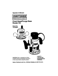
OPERATOR'S MANUAL
7-1/4 in. CIRCULAR SAWWITH LASER GUIDE
DOUBLE INSULATED
Model No.
315.108620
WARNING: To reduce_herbk of injury,
the user must read and understand the
operator's manual before using this product.
Customer Help Line: 1-800-932-3188
Sears, Roebuck and Co., 3333 Beverly Rd., Hoffman Estates, IL 60179 USA
Visit the Craftsman web page: wwwosears.com/craftsman
983000-B17
9-05 (REV:01)
Save this manual for future reference
m Warranty .............................................................................................................................................................................
2
m Introduction .....................................................................................................................................................................
2
[] General Safety Rules ....................................................................................................................................................
3-4
u Specific Safety Rules .....................................................................................................................................................
4-5
[] Symbols ........................................................................................................................................................................
6-7
[] Electrical ..........................................................................................................................................................................
8
B Features ........................................................................................................................................................................
9-10
[] Assembly ..................................................................................................................................................................
10-12
[] Operation ..................................................................................................................................................................
13-20
[] Adjustments ...................................................................................................................................................................
21
m Maintenance ....................................................................................................................................................................
22
nl Exploded V_ewand Parts List.........................................................................................................................................................................................
23-24
[] Parts OrderinglService ........................................................................................................................................
Back Page
ONE-YEAR FULL WARRANTY ON CRAFTSMAN TOOL
If this Craftsman tool fails to give complete satisfaction within one year from date of purchase, RETURN IT TO ANY
SEARS STORE OR PARTS AND REPAIR CENTER OR OTHER CRAFTSMAN OUTLET IN THE UNITED STATES FOR
FREE REPAIR.
If this Craftsman tool is used for commercial or rental purposes, this warranty applies for only 90 days from the date of
purchase,
This warranty gives you specific regal rights, and you may a|so have other rights whtch vary from state to state,
Sears, Roebuck and Co., Dept. 817WA, Hoffman Estates, IL 6017g
This tool has many features for making its use more pleasant and enjoyable. Safety, performance, and dependability
have been given top priority in the design of this product making it easy to maintain and operate.
A
WARNING! Read and understandall instrue'dons.Failureto follow aJlinstructions listedbelow,
may resultIn electricshock,fire and/or serious
personal
injury_
SAVE THESE INSTRUCTIONS
before plugging In. Carrying tools with your finger on
the switch or plugging in tools that have the switch on
invitesaccidents.
•
I
WORK AREA
[] Keep your work area clean and well lit. Cluttered
benches and dark areas invite accidents_
B Do not operate power tools in explosive atmospheres, such as In the presence of flammable liquids, gases, or dust. Powertoolscreatesparkswhich
may ignitethe dust or fumes.
[] Keep bystanders,children, and visitors away while
operating a power toot. Distractions can causeyou to
lose control,
ELECTRICAL
SAFETY
[] Double insulated tools are equtpped with a polarized plug (one blade is wider than the other), This
plug will fit in a polarized outlet only one way. If the
plug does not fit fully in the outlet, reverse the plug,
If it still does not fit, contact a qualified electrician
to install a polarized outlet. Do not change the plug
in anyway. Double Insulation [] eliminates the need
for the three-wire grounded power cord and grounded
power supply system.
= Avoid body contact with grounded surfaces such as
pipes, radiators, ranges and refrigerators. There is an
increased risk of electric shock if your body is grounded°
II Don't expose power tools to rain or wet conditions.
Water entering a power tool will increase the riskof
electric
shock,
[] Do not abuse the cord. Never use the cord to carry
the tools or pull the plug from an outlet. Keep cord
away from heat, oil, sharp edges or moving parts.
Replace damaged cords immediately. Damaged
cords increase the risk of eiectdc shock.
[] When operating a power tool outside, use an outdoor
extension cord marked "W-A" or WV". These cords
are rated for outdoor use and reduce the risk of electric
shock.
PERSONAL SAFETY
[] Stay alert, watch what you are doing and use common sensewhen operating a powertool Do not
use toot while tired or under the influenceof drugs,
alcohol, or medication.A momentof inattentionwhile
operdtingpower tools mmyresult inserious personai
injury.
[] Dress properly. Do not wear loose clothingor
jewelry. Contain long hair. Keep yourhair, clothing,
and glovesaway from moving parts. Looseclothes,
jewelry,or long hair canbe caught in moving parts.
• Avoidaccidentalstarting. Be sure switchIs off
•
•
Remove adjusting keys or wrenches before turning
the too! on. A wrench or a key that is left attached to a
rotating par_ of the tool may result in personal lnjury.
Do not overreach. Keep proper footing and balance
at all times, Proper footing and balance enables better
control of the too_ in unexpectedmtualicnso
Use safety equipment. Always wear eye protection.
Dust mask, non-skid safety shoes, hard hat, or hearing
protection must be used for appropriate conditions
Do not wear loose clothing or Jewelry. Contain long
hair. Loose clothes, jewelry, or long hair can be drawn
into air vents.
[] Do not use on a ladder or unstable support. Stable
footing on a solid surface enables better control of the
tool in unexpected siluations.
TOOL USE AND CARE
B Use clamps or other practical way to secure and
support the workpiece to a stable platform. Holding
the work by hand or against your body is unstable and
may lead to loss of control
[] Do not force tool, Use the correct tool for your application. The correct tool will do the job better and
safer at the rate for whJch it is designed.
u Do not use tool if switch does not turn it on or off.
Any t_l that cannot be controlled w(th the switch is
dangerous and must be repaired,
[] Disconnect the plug from power source before
making any adjustrnentsj changing accessories,
or storing the tool. Such preventive safety measures
reduce the risk of starting the too! accidentally.
[] Store Idle tools out of reach of children and other
untrained persons. Tools are dangerous In the hands
of untrained users.
[] Maintain tools with care. Keep cutting tools sharp
and clean. Property maintained tows with sharp cutting edges are tess likely to bind and are easier to
control.
[] Check for misalignment or binding of moving parts,
breakage of parts, and any other condition that
may affect the tool's operation. If damaged, have
the tool serviced before using, Many accidents are
caused by poody maintained
tools,
[] Use cnhJaccessories that are recommended by the
manufacturer for your model. Accessories that may
be suitable for one toot, may become hazardous when
used on another tool
I Keep the tool and its handle dry, clean and free
from og and grease. Always use a clean cloth when
clBaning_ Never use brake fluids, gasoline, petroleumbased products, or any strong solvents to clean your
too!. Following this rule will reduce the risk of loss of
con_oland delefioration
oftheenclosureplastic,
SERVICE
[] Tool service must be performedonly by qualified
repair personnel.Serviceor maintenanceperformed
by unqualifiedpersonnelcouldresultin a riskof injury.
=' When servtc]nga tool, use only Identical replacement parts. Followinstructions in the Maintenance
section of this manual. Use of unauthorizedpartsor
failure to follow MaintenanceInstruct_ons
may createa
riskofelectricshockor injury,
I
i
DANGER! Keep hands away from cutting area and
blade. Keep your second handon auxiliaryhandle or
motor housing.If bothhandsare holdingthesaw,they
cannot be cutby 1heblade°
• Keep your body positionedto either side of the saw
blade, but not in line with the saw blade. Kickback
could cause the saw to jumpbackwards. (See "Causes
AndOperator Preventionof Kickback" later..)
[] Do not reacll underneaththe work. The guard cannot
protect you from the blade below the work,
== Checklowerguardforproper closing beforeeachuse.
Do notoperatesawiflowerguard doesnotmovefreely
andcloseinstanlJy.Never cramporhethe lowerguard
into the open posiUon.If saw is accidentally dropped,
lowerguardmay be bent. Raisethelower guard withthe
retractinghandleand makesureit movesfreely and does
not touch the blade or any other part, in all angles and
depths of cut,
m Checkthe operationand cond'dlonef the lowerguard
spdng, If the guard and the springare not operating
properly,theymustbeservicedbeforeuse.Lowerguard
may operatesluggishly due to damaged parts, gummy
deposits, or a buitdup o_debris.
= Lower guard should be retracted manually only for
specialcuts, such as "Pocket Cuts"and =Compound
Cuts." Raiselowerguardbyretractinghandle.Assoon
as blade enters the material, lower guard must be
released. For all othersawing,the lowerguardshould
operate automatically.
m Always observethat the lower guard is coveringthe
bladebefore placingsaw down on benchor floor.An
unprotected, coastingblade wi!l causethe saw to walk
backwards, cutting whateveris in its path. Be aware of
the time it takes for the blade to stop after switch is
released
H NEVERhold piece being cut in your handsor across
your leg. tt is important to supportthe work properly
to minimize body exposure,blade binding,or loss of
control
i Hold tool by insulated gripping surfaces when
performingan operation where the cutting tool may
contact hiddenwiring or its own cord. Contactwith a
"live"wirewiilmake exposedmetal partsef thetool=live_
and shock the operator.
[] Whenripping,always use a ripfence er straight edge
guide. Thisimprovesthe accuracyofthe cut and reduces
the chancefor blade binding°
!
Always use blades with correct size and shape
Idtamond vs. round) arbor holes. Blades that de
not match the mounting hardware of the saw wltl run
eccentrically, causing loss of contre£
Never use damaged or incorrect blade washers
or bolts. The blade washers and belts were specially
des'_gnedforthe saw for optimum performance and safety
of operation,
Causes and Operator Prevention of Kickback:
Kickback is a sudden reaction to a pinched, bound, or
misaligned saw blade, causing an uncentre{ied saw te lift
up and out of the workpiece toward operator.
When the blade is pinched or bound t{ghtJyby the keffclesing
down, the blade sta(Is and the motor reaction drives the unit
rapidly back toward the eperaton
If the blade becomes twisted or misatigned in the cut, the
teeth at the back edge of the blade can dig into the top
surface of the wood causing the blade to c{Imb out ef the
kerr and jump back toward the operator,,
Kickback isthe result ofteol misuse and/or incorrect operating
procedures or conditions and can be avoided by taking proper
precautions, as given below:
[] Maintain a firm grip with both hands on the saw and
position your body and _rm to allow ye_ to resist
kickback {orcee. Kickback forces can be centro{{ed by
the operator, if proper precautions are taken.
u When blade is binding, or when interrupting a cut
for any mason, release the trigger and hotd the saw
motionless in the material until the blade comes to a
complete stop. Never attempt to remove the saw from
the work or pull the saw backward while the blade is
in motion, or KICKBACK may occur. Investigate and
take corrective actions to eliminate the cause of blade
binding,
[] When restarting a saw in the workpiece, center the
saw blade in the kerf and check that saw teeth are
not engaged Into the material, tf saw blade is binding,
it may walk up or KICKBACK from the workpiece as the
saw is restarted.
•
St_pport large panels to minimize the risk o1 blade
pinching and KICKBACK. Large panels tend to sag
under their own weight. Supports must be placed under
the panel on both sides, near the iine of cut and near the
edge of the panel.
m Do not use dull or damaged blade, Unsharpened or
improperly
set bladesproducenarrowkerfwhich causes
excessivetriton, blade binding andK_CKBACKo
m Blade depth and bevel adjusting locking levers
mustbe tight and securebefore making cut. If blade
adjustment shiftswhitecutting,it may causebinding and
KICKBACK.
m Make sure your extension cord is in good condition,
When using an extension cord, be sure to use one
heavy enough to carry the current your product
will draw. A wire gage sLze (A.W.G.) of at least 12 is
recommended
for an extension cord 50 feet or
tess in length,
recommended,
The smaller the
undersized cord
in loss of power
m Use extra cauUonwhen making a "Pocket Cut" into
ex_stingwalls or otherblindareas.Theprotrudingblade
may cutobjectsthat can cause KICKBACK.
It Knowyourpower tool. Read operator'smanualcarefully. Learn its applications and limitations, as well
as the specificpotential hazards related to this tool.
Followingthis rule willreducethe risk of electric shock,
fire,or serious injury.
m Always wear safety glasses. Everyday eyeglasses
haveonlyimpact-resistantlenses;theyare NOT safety
glasses.Following1hismlewill reducethe risk of serious
personal injury.
=t Protect your lungs.Wear a face or dust mask if the
operation is dusty. Followingthis rulewifl Teducethe
riskof seriouspersonalinjury.
m Protectyour hearing.Wear hearingprotectionduring
extendedperiods of operation.Fo_ing '_hisrule will
reducethe riskof serious personalinjury.
i Inspect toolcords pertodicallyand,if damaged, have
repaired at your nearest authorized service center.
Constantlystay aware of cordlocation. Following this
rulewillreducethe riskofelectricshockor fire.
Check damaged parts, Before further use of the
tool, a guard or other part that is damaged should
be carefullychecked to determine that it will operate
properlyandpederm its intendedfunction. Check for
alignmentof moving parts, bindingof moving parts,
breakageof parts_mounting,and anyotherconditions
that may affectitsoperation.Aguardor otherpart that
is damaged should be properly repairedor replaced
byan authorizedservicecenter.Followingthisrulewill
reducethe risk of shock, fire, or sedous Injury.
I
A cord exceeding 100 feet is not
tf in doubt, use the next heavier gage.
gage number, the heavier the cord. An
wiltcause a drop in line voltage resulting
and overheating.
Inspect for and remove all nails from lumber before
using this tool, Folio'wing this rule wilt reduce the risk of
serious personal injury.
Laser
Guide
Warnings:
The laser guide radiation used in the Craftsman circular saw
is Class Ilia with maximum 5mW and 650nm wavelengths,
These lasers do not normally present an optical hazard
although stadng at the beam may cause flash blindness.
m Avotd direct eye exposure when using the laser guide.
m The laser shall be used and maintained in accordance
with the manufacturer's Instructions.
!
Never aim the beam at a person or object other than the
workpiece.
m Always ensure the laser beam is a(med at a sturdy
workpiece without reflective surfaces, Shiny reflective
sheet metal or similar shiny materials are not suitable for
laser use.
m NI repairs should be made by an authorized service
representative or the laser manufacturer.
IE Save these instructions, Refer to them frequently and
use them to Instruct others who may use this tool tf you
loan someone this too_, loan them these instructions
also.
_1= WAFIN|NG: Somedust createdby powersanding, sawing, grinding, drilling, and otherconstruction
activities
contains chemicalsknown to causecancer,blrth defects or otherreproductiveharm. Some examplesof these
chemicalsam:
=_ead_remlead-basedpaints,
* crystallinesfflca from bricks and cement and other masonry products, and
J arsenic andchTomium
from chemically-treated _Umb_ro
Your risk from these exposuresvaries, depending on how often you do this type of work, To reduce your exposure
to these chemicals:work in a well ventilatedarea, and work withapproved safety equipment, such as those dust
masks t'natarespeda]ly designedto filterout microscopic particles.
Some of the following symbols may be used on this tool, Please study them and learn their meaning_ Proper interpretation of these symbols wlll allow you to operate the tool better and safer,
SYMBOL
NAME
V
DESIGNATION/EXPLANATION
Volts
Voltage
,11
,,i,i
A
ii
Amperes
iii
i
Current
IH
Hz
Hertz
Frequency (cycles per second)
i
W
,
iI
I J
ijllllllllll,lllllll,,lllllllllllll'l,lllll,
ll'l'll
Watt
Power
Minutes
Time
"k,
Alternating Current
Type of current
==
Direct Current
Type or a characteristic of current
no
No Load Speed
Rotational speed, at no load
rain
iii
[]
.Jmin
ii
i,
i ,IIIIIIH,II
CIass il Construction
Double-insulated construction
Per Minute
Revolutions, strokes, surface speed, orblts etc. per minute
i
Wet Conditions Alert
Do not expose to rain or use in damp locations.
Read The Operator's Manual
operator's
manual
before
pmducto
To reduce the
risk of
Injury,using
userthis
must
read and understand
i ii
Eye Protection
Q
,,
,,, ,,
,,
i
i
iii
H HHHHHH,H,H,HH'H',
I
I
s,iety
A,e.
your safety.
Precautions.hat
,ovo,vo
No Hands Symbol
serious
injury°
Failure topersonal
keep your
hands away from the blade wtll result in
No Hands Symbol
Failure
keep your
serious topersonal
inju_hands away from the blade will result in
.,,,,,,,,,,,,,,,,,,,,,,,,,,,
No Hands Symbol
IHII
i iiiiiiiii
Always
wear
safety
goggles,
safety
a
full face
shield
when
operating
thisglasses
product.with side shields, or
i
,
i i i ii
Failure topersonal
keep your
hands away from the blade will result in
serious
injury°
:::::::::::::::::::::::
No Hands Symbol
Failure topersonal
keep your
hands away from the blade will result in
serious
injury.
Hot Surface
To
the risk of injuryor damage, avoid contact with
anyreduce
hot surface.
H ,,H H,HHHHH,,,,HHH
6
I
Thefollowing
signal
words
andmeanings
areintended
toexplain
thelevels
ofrisk associated
with this
product.
SYMBOL
SIGNAL
MEANING
DANGER:
Indicates an imminently hazardous situation, which, if not avoided, will
result in death or serious injury.
H
A
A
A
Indicates a potentially hazardous situation, which, if not avoided, coWd
result in death or serious injury.
WARNING:
CAUTION;
Indicates a potentiallyhazardoussituation, which,if not avoided,may
resultinminor or moderate injury.
CAUTION:
(WithoutSafety Alert Symbol) Indicates a situation that may result in
property damage,
SERVICE
Servicing requiresextremecare and knowledge and
should be performedonly by a qualified service technician. For servicewe suggest you return the product to
your nearest AUTHORIZEDSERVICE CENTERfor repair.
When servicing, use only identical replacementparts.
•_
WARN|NG: To avoid serious personalinjvry,do not
attempt to use thls product untieyou read thoroughly
andunderstandcomp|etelythe operators manual
Save this operator'smanual and review frequently for
continuing safe operationand instructing others who
may use thisproduoto
_l_ll,WARNING:
The operation of any power tool can result in foreign objects being thrown into your eyes, which
can result in severe eye damage. Before beginr_ing power too! operation, ak_ays wear safety
goggles, safety giasses with side shields, or a full face shield when needed. We recommend Wide
Vision Safety Mask for use over eyeglasses or standard safety grasses with side shields.
Atways use eye protection which is marked to compfy with ANSI ZBT.1.
SAVE THESE INSTRUCTIONS
DOUBLE INSULATION
EXTENSION
Doublelnsulatlon ts a concept tn safety tn electric power
tools, whicheliminatesthe need for the usualthree-wire
grounded power cord_All exposed metal parts are
isolatedfrom the internal metal motor componentswith
protecting insulation. Double insulatedtools do not need
to be grounded.
When using a power tool at a considerable distance from
a power source, be sure to use an extension cord that has
the capacity to handle the current the tool will draw. An
undersized cord will cause a drop in tine voltage, resulting
in overheating and loss of power. Use the chart to determine the minimum wire size required in an extens(on cord°
Only round jacketed cords listed by Underwriter's Laboratories (UL) should be used,
'_
WARNING: The doubleinsulated system is
intended to protect the user from shock resulting
from a break in the tool's internalinsulation, Observe
a{tnormal safety precautionsto avoid electdcat
shock,
NOTE:Servicing of a tool with doubteinsulationrequires
extreme care and knowledge of the system and should
be performedonly by a qualified servicetechnician. For
eervtce,we suggest you return the tool to your nearest
authorizedservice center for repair.Alwaysuse origina)
factory replacementpads whenservicing.
ELECTRICAL CONNECTION
Thistool has a precision-built electric motorr It should be
connectedto a power supply that is 120 rolL% 60 Hz,
AC only {normalhouseholdcurrenl_.Do not operate
thistool on direct current (DC}.A substantial voltage drop
wiltcause a toss of power and the motor will overheat,if
your toot does not operate when plugged into an outlet,
double-check the power supptyo
CORDS
When working outdoors with a tool, use an extension
cord that is designed for outside use. This type of cord is
designated with "WA" on the cord's jacket.
Before using any extension cord, inspect it for toose or
exposed wires and cut or worn insulation.
0-2,0 2,1-3.4 3.5-5.0 5.1-7.0 7,1-12.0 12.t-16.0
Cord Length
Wire Size (A,W.G.)
25'
16
16
16
t6
14
14
50'
16
t6
16
!4
14
12
IDOL
16
I6
14
12
10
--
•"Usedon fZ ga_. 20 ampcir_ui!
NOTE:AWG= American
WireGaUge
WARNING: Keep the extension cord dear of the
working area, Posfttonthe cord so that It will not get
caught on lumber, tools or other obstruotiot_s while
you are working with a power toolo Failure to do so
can resuff inserious personal injury.
A
WARNING: Check extensioncords before each
use,ff damaged replace immediately.Neveruse tool
with a damagedcord since touching the damaged
area coutd cause etectricalshock resuttingin serious
injury.
PRODUCT
I
SPECIFICATIONS
Blade Diameter .................................................... 7-1/4 ino
!1 Blade Arbor ............................................................
5/8 in.
II Input............................120 V,60 Hz, AC Only, 14 Amps
Ii No Load Speed..............................................5,0O0/min.
il Cutting Depth at 90 °,.......................................... 2-3/8 in.
w Net Weight ...........................................................
11 Ibs.
II Cuffing Depth at 45 °,.................................... %13/16 in.
I! LaserGuide ...................Class Ilia, <5mWmax, 850 nm
II Cutting Depth at 51,5 °, ..................................... 1-5/8 in,
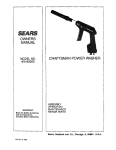
DEPTH
ADJUSTMENT
KNOB
VIRTUAL
EDGEGUIDE
ADJUSTMENT
IOIOR
UPPERBLADE
GUARD
/
SPINDLE
LOCK
BEVEL
SCALE
BEVEL
ADJUSTMEEIT
LEVER
BLADE
GUARD
BLADE
WRENCH
STORAGE
\
REARLASER
GU!OE
LIVETOOL
INDICATOR
Fig° 1
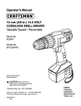
KNOW YOUR CIRCULAR SAW
See Figure 1.
Before attempting to use thisproduct,familiarizeyourself
with all operating featuresand safetyruleso
DUST COLLECTION
To direct sawdust and chips away from the operator,
a dust chute is located on the side of the upper blade
guard.To collect sawdust, a standard vacuum hose can
be attached tothe dust chute using the adapter and dust
nozzle provided.
ERGONOMIC DESIGN
The design of yourcircular saw provides for maintaining
proper two hand control when cutting, It has been
designed to be comfortable and easy to grasp,
LASER GUIDES
The saw Is equipped withtwo laser guides, the rear laser
guide and the Virtual Edge Guide.The laser guides will
generate a red coloredlaser bea'n on the work surface in
front of andbehind the saw when turned on,
LIVE TOOL INDICATOR
The live tool indicator is locatedon the handleof the
saw and indicatesthat the tool Is connectedto a power
supply,
SPINDLE LOCK
The splndte lock allows you to secure the blade when
turning the blade screw,
NOTE: Do not run circular saw with spindle lock engaged.
A
UNPACKING
This product requiresassemblyo
m Carefullyremove the tool and any accessoriesfrom the
box. Make sure that all items listed in the packing list
arelnctuded_
A
w Inspect the tool carefully to make sure no breakageor
damage occurred duringshipping.
WARNING: If any parts aredamaged or missing do
not operate this tool until the damaged or missing
parts are repfaced,Failurs to do so couldresult in
possibteseriouspersonal injury.
WARNING: Do not attempt to modify this tool
or create accessories not recommended for use
with this tool, Any such aPteralion or modification _s
misuse and could result In a hazardous cond(tton
s Do not discard the packing material until you have
carefut_tinspected and satisfactorily operatedthe too!,
leading to possible serious personat injury.
w if any parts are damaged or missing, please call
1-800-932-318Bfor assistance.
WARNING: Do not connectto power supply until
assembly Is complete.Fatlureto complycould result
in accidental starting and possible serious injury,
PACKING LIST
Circular Saw
7-!/4 in. Blade
Dust Chute Adaptor
Dust Nozzle
Wrench
Case
Operator's Manual
10
_l_
I
Re&act the Zowerblade guard into the upper blade
guard using the lower blade guard hand(e_ Make sure
the tower guard spring works properly, allowing the
guard to move free_y,
m Check to see that the saw teeth and arrow on the saw
blade and the arrow on the lower guam are pot_ng tn
the same direction.
NOTE; The saw teeth point upward at the front of the
saw as shown.
WARN|NG: 7-1/4 in. b|ade is the maximum blade
capacity of the saw. Also, neverusea blade that is
too thick to aliow outer blade washer to engagewith
the flat on the spindle. Larger bladeswiltcomein
contactwith the blade guards, whilethicker btadss
will prevent blade screw from securing blade on
spindle. Eitherof thesesituations could result in a
serious accident.
m ;=Itthe saw blade Inside the lower blade guard and
onto the spindle,
CAUTION: Toprevent damageto the spindle
or spindle lock, alwaysallowmotor to come to a
complete stop before engaging spindlelock.
E Replace =D" washer.
= Replace spring washer with cupped side against
"O" washer.
ATTACHING BLADE
See Rgures 2 - 3.
= Unplugthe saw.
= Depress spindle lock button and replace blade SCraw,r
II Tighten blade screw securely by turning it clockwise
with the wrench.
n Depressspindle lock button.
= Removeb[ade screw by turning it counterolockwise
withthe wrench,while keeping the spindle lock button
depressed,
m Removespring washerand outar blade washer
("D" washer).
I=!Wipe a drop of oil ontothe innerflange bushingand
outer blade washer("D" washer)wherethey contact
blade.
,_
NOTE; Never use a b)ade that is too thick to a!low the
"D" washer to engage with the fiat on the spindle.
OUTER
BLADE
WASHER
WARN|NG: If innerflange bushing has been
removed,replace it before placing blade on spindle.
Failureto do so will prevent blade from tightening
properly and could result In seriouspersonal injury.
UPPEDSIDEOF OUTSIDE
OFSPRING
PRINGWASHER
WASHER
BLADEGUARD
N_DLE
BUSHING
/
OUIERWASHER
-
/"
BLADE
BLADE WASHER
Fig. 2
tl
Fig, 3
REMOVING BLADE
See Figure4_
m Unplugthe saw.
ATTACHING DUST CHUTE ADAPTER AND DUST
NOZZLE
See Figure5,
II Depressspindle lock button,
II Removeblade screw by turning it counterclockwise
with the wrench.
NOTE: tf you use thedust nozzle,you should always
connect it to a standard vacuum hose.
n Removespring washer and outer blade washer
("D_ washer),
= Lift lower blade guard.
!1 Orient adapterto fit into the dust chute opening on
upperbladeguard.
m Unplug thesaw.
= Lift lower blade guard.
III Removeblade_
m Secureadapterwlth screw provided.
m Align hotein nozzlewi',_hraised lip on adapter and snap
into place.
m Attach standard vacuum hoseto nozzle.
NOZZLE
HOLE
Fig. 5
Fig, 4
12
To guard against kickback, avoid dangerous practices
such as the following:
,_& WARNING: Do not allow familiarity with tools
to make you careless, Rememberthat a careless
fraction of a second is sufficient to inflict serious
injury.
m Setting blade depth incorrectly
•
Sawing into knots or nails in workpiece
[] Twisting the blade while making a cut
,_
WARNING: Alwayswear safety goggles or safety
glasseswith side shields when operating power
tools. Failureto do so couldresult in obiectsbeing
thrown intoyoureyes resultingin possible serious
injury,
•
Making a cut with a dull, gummed up, or improperly s_
blada
•
Supporting the workpiece incorrectly
•
Forcing a cut
[] Cutting warped or wet lumber
[] Operating the tool Incorrectly or misusing the tool
_k
WARNING; A)waysunplug the tool when changing operationsettings or whenthe tool is not in use,
Failureto unplug the toolmay resuff inaccidental
startingand serfouspersonalinjury.
APPLICATIONS
You may usethis toolfor the purposes listed below:
m Cross Cutting/Rip Cutting
[] BevelCutting
[] Plunge Cutting
No More than 1t4 inch
KICKBACK
See/figures 6 - 8o
KICKBACK
- BLADE
SETTOODEEP
Kickback occurs when the blade stalls rapidly andthe
saw is driven back towards you, Blade staiting is caused
by any action which pinches the blade In the wood°
Fig,6
_!_ DANGER: Releaseswitch immediately if blade
binds or saw stalls, Kickback could cause you to
lose control of the saw.Loss of control can lead to
serious personalinjury°
13
To lessen the chance of kickback,
practices,
I
follow
SAW BLADES
these safety
The best of saw bladeswill not cut efficientlyif they are
not kept clean, sharp, and properly set. Using a dull
blade wit1placo a heavy load on the saw an6 increasethe
danger of kickback. Keep extra blades on hand,so that
sharp blades are always available.
Gum and wood pitch hardened on b_adeswill s_owthe
saw down. Removesaw blade from the saw and use gum
and pitch remover,hot water, or keroseneto removethese
accumulations. DO NOT USE GASOLINE.
Keep the blade at the correct depth setting. The depth
se_ng should not exceed 114in. below the material being
ct_
[] Inspect the workpleoe for knots or nails before cutting.
Never saw into a knot or nail.
[] Make straight cuts, Always use a guide when dp
cu'tting_This helps prevent twisting the blade,
Ill Use clean, sharp, and propedy set blades° Never make
cuts with dull blades.
[] Suppor_ the workpiece property before beginning a cut,
[] Use steady, even pressure when making a cut Never
force a cut,
[] Do not cut warped or wet lumben
I Hotd the saw firmly with both hands and keep your
body tn a balanced position so as to resist the forces If
kickback should ooouro
_I,
BLADE GUARD SYSTEM
See Figure 9.
The lower blade guard attached to the cimuJarsaw is
there for yourprotection and safety. Do not alter it for any
reason, if it becomes damaged,do not operate the saw
untit you have the guard repaired or replaced. Always
leaveguard In operating position when using the saw.
_lb DANGER: Whensawing through work, lower blade
guarddo_s not coverblade on the und_si6e of
work. Since blade is exposed on underside of work,
keep hands and I_ngersaway from cutting area.Any
part of yourbody coming in contact with moving
blade witl result tn serious injury.
WARNING'- When using the saw, atways stay alert
and exercise control Do not remove the saw from
the workpfece while the blade Is moving.
_!,
CAUTION: Neveruse saw when guard is not
operating correctly. Ch_k the g_ard for corral
operationbefore each use.The guard )s operating
correctly when it moves freatyand readily returns
to the closed position. If you drop the saw, check
the lower blade guard and bumper for damage at all
depths_ttings
before reu_.
INCORRECT
SUPPORT
Fig. 7
/
LOWERBLADE
GUARD
IS IN UP
PDSI!lONWHENMAKING
A CUT
Fig.
g
CORRECT
SUPPORT
Fig. 8
14
STARTING/STOPPING THE SAW
See Figure 10,
WARNING; Nways unplug the toot when chang[ngoperationsettings or when the tool is not in use.
Failure1o unplug the tool may result in accidentaK
starting and sedous persona_Injury.
Tostart the sam Depressthe switch trigger.
Ah_ayslet the b_adereach f,j_)speed, then gu)dethe saw
into the workp]ece.
ADJUSTING BLADE DEPTH
See Figure11.,
_1_ WARNING: The b)ade comingin contact w_ththe
workp]ese before It reachesfull speed could cause
the saw to "kickback" towards you resulting in
serious personal injury.
Alwayskeepcorrectblade depthsalting. The correct
blade depth setting for al! cuts shoutd not exceed 1/4 in,
below the matefia! being cut. More btade depth wilt
increasethe chance of kickback end cause the cut to be
rough. For more depthof cut accuracy,a scale islocated
on the upper blade guard.
To stop the saw: Release the switch trigger.
NOTE: Allow the blade to come to a complete stop before
removing saw from workpleoe.
II
m
i
m
Unplug the saw.
Loosen depth adjustmentknob.
Determinethe desireddepth of cut.
Locate depth of cut scale on back of upper blade
guard.
aNHoldbase flat agair_._'t
the workpieceand reiseor lower
saw _nti{the indicator mark on bracket alignswith
notch on blade guard°
BI Tighten depth adjusb'nentknob securely.
DEPTH
OFCUT
Fig. 10
Fig. 11
15
OPERATING THE SAW
See Figures 12 - 14,,
It is important to understand the correct method for
operatingthe sawnRefer to the f/gums in this section to
learn the correct and incorrect ways for handling the saw,
,_
WARNING: To make sawingeasier andsafer,
always maintain propercontrolof the saw° Loss of
controlcoutd cause an accident resulting in possible
serious personal ln]uryo
_1_ DANGER: When lifting the saw from the work'piece,
the blade is exposed on the underside of the saw
until the lower blade guard closes° Make sure the
lower blade guard is closed before setting the saw
down.
To make the best possiblecut, follow thesehelpful hints.
m Hold the saw firmly with both hands.
m Avoid placing your hand on the workptece while
making a cut.
I
Im Support the workpiece so that the cut (kerr)is always
to your side,
[] Keep the cord away from the cutting area. Always
placethe cord to prevent it from hanging up on the
workpiecewhilemaking a cut.
[] Support the workpiece near the cut.
Draw a guideline along the desired line of cut before
beginningyour cut.
_
DANGER_ If the cord hangs up on the workplece
during a cut, releasethe switch trigger immediately.
Unplugthe saw and reposition the cord to prevent it
from hangingup again.
_,
DANGER_ Using a saw with a damaged cord could
result in serious personal injury or death. If the cord
has been damaged, have It replaced before using
the saw again.
Fig. 12
= Clamp the workpiece securelyso that the workpiece
wilt not move during thecut.
t Always place the saw on theworkplece that is supported, not the "cut off"piece,
III Race the workpiecewith the "good" side down.
16
,_
LASER
GUIDE
DUTTDN
WARNING: Do not stare into thetaserbeams or
turn the laserson when the tool is not in use, Failure
to do so couldresult in possible serious personal
tnjur/_
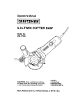
USING THE LASER GUIDES
See Figures 15- 16.
The laser guides will generate a red colored laser beam
on the work surface in front of and behind the saw when
turned on, The front laser or Virtual Edge Guide can be
ad}usted for use as an edge guide w_h a scale of 0 - 6 ino
The rear laser afdes in aligning plunge cuts and following
the kerf when exiting the workpiece.
VIRTUAL
EDGEGUIDE
ALIGNMENT
NEEDLE
NOTE: The laser units come from the factory atready
installed and aUgned, If the rear laser guide becomes
misaligned after time, refer to the Adjustments section for
realignment instructions_The Virtual Edge Guide requires
no further alignment,
m Mark the line of cut on the workpiece.
= Push in and turn the Virtual Edge Guide adjustment
knob until the needle is aligned to the desired position
on the Virtual Edge Guide sca_e,
la Adjust the depth and angle of the cut as needed
m Plug the tool into a power supply and press the laser
gutde button to activate the _aser,
m Start the motor.
NOTE; Do not touch the blade to the workplece until
the saw has reached maximum speed,
[] Slowly push the saw forward into the workpiece.
NOTE: Keep the laser beam on the marked line on the
workpiece for precision cutting,
= Once the cut is complete, allow the saw to come to a
complete stop before turning off the taser.
REARLASER
GUIDE
= Unplug the saw,
LASERGUIDEBUTTON
Fig, 16
"',,
VIRTUAL
EDGE
GUIDE
VIRTUAL
EDGE
GUIDE
ADJUSTMENT
KNOB
Fig, 15
17
BEVEL CUTTING
See Figures 19 - 2&
CROSS CUI-I'ING/RIP CUTTING
See Figure17",
Whenmakinga crosscut or rip cut, alignthe lineof cut
withthe outer blade guide notch on the base as shown in
the figure.
Since blade thicknessesvary, always make a tdal cut
in scrapmateriaJalonga guidelineto determine how
much, if any, you must offset the guideline to produce an
accurate cut.
! Align the lineof cut with the innerblade guide notch on
the base when making 45" bevel cuts.
R Make a trial cut In scrap material along a gutdellneto
determine how much you should offset the guideline
on the cutting materia!.
= Adjust the angle of the cut to any deelred setting
between zeroand 5!.5 _.Referto To Adjust Bevel Setring.
NOTE:The distance from the line of cutto the guideline is
the amountyou should offset the guide.
TO ADJUST BEVEL SETTING
See Figure f9
TOPVIEWOFSAW
[] Unplug the circularsaw.
m Lift bevel adjusb'nentlever up.
[] Raise motor housing end of saw until you reach des_redan£tieset_in_{In bevel scale,
I Lower bevel adjustment tever until motor housing is
locked Into pface.
BLADE
GUIDE
NOTCH
,_
WARNING: Attempting a bevel cut without having
the bevel adjustment leversecurelytightened can
result in serious personalinjury.
GUIDEUNE"
LENGTH OF CUT SCALE
See Figure18o
The saw isequipped with a length of cutscale on itsbase,
It Is parallel with the saw blade and you can use it to measure the distance into the material the blade cuts.
NOTE:Six inchesisthe maximum length of cut that you
can measure.Also, it [s accurate only when the depth of
cut isset at full maximum depth.
BLADE
GUIDENOTCH
Fig. 19
/
LENGTH
OFCUT
SCALE
Fig. 18
18
CHECKING POSITIVE 0° BEVEL STOP
MAKING A BEVEL CUT
See Figure20
[] Unplug the circularsawr
= Placethe saw in an upside downposition on a workbench,
" HoTdthe saw firmlywith bothhandsas shown,
i
i
Restthe front edge ofthe baseon the workpieceo
Startthe saw and let the blade reach full speed°
[] Check the squarenessof thesaw bladeto the base of
thesaw usinga carpenter's square.
m Guide the saw intothe workpiece and make the cut,
[] Releasethe switch trigger and allow the blade to come
to a completestop,
ADJUSTING POSITIVE 0° BEVEL STOP
[] Lift the saw from the workpiece,
[] Lift beve_adjustment _everup,
[] Unplug the circularsaw.
[] Turn setscrew with hex key and adjust base until it is
squarew_ththe saw b}ade.
[] Lowerbevel adjustmentleveruntilmotorhousing is
lockedinto place.
_
WARNING: Attempting a bevelcutwithouthaving
the beveladjustment leversecurelytightenedcan
resultin serious personalinjury°
CARPENTEIt'S
Fig, 20
SETSCREW
POSITIVE 0 ° BEVEL STOP
See Rgum 21o
,_lk WARN|NG: Failureto unplug the tool couldresult in
accidental starting causingserious personal injury.
The saw has a positive 0° bevel stop that has been factory
adjusted to assure 0° angle of the saw blade when making
90 ° cuts.
Fig. 21
19
PLUNGE cUTrlNG
See Rgums 22.23.
_L
WARN|NG: Ahvaysadjust bevel se_ng to zero
before making a plunge cut. Attempting a plunge cut
at any other settingcan resuff in ioss of control of the
saw possibly causingserious personal injury,
m Adjust the bevel setting to zero,
m Set the blade to the correct blade depth setting°
E Swing the lower blade guard up using the lower blade
guard handle.
NOTE;Always raise the lower blade guard with the
handle to avoid serious persona] injury.
= Hold the lower blade guard by the handle.
E Restthe front ofthe baseflat against the workpiece
with the rear of the handle raisedso the blade does not
touchthe workpiece.
m Start the saw and let the blade reach fut[ speed.
m Guide the saw into the workp}eceand make the cut_
LOWER
BLADE
GUARD
PLUNGE
CUT
Fig, 22
,_IIL WARNING: Ahvayscutin a forward dire_ion when
pfungecutting.Cutting inthe reversedirectioncould
causethe sawto climb up onthe workpleceand
back toward you.
[] Release the switch trigger and allow the blade to come
to a complete stop.
[] Lift the saw from the workpiece.
[] Clear corners out with a hand saw or sabre saw.
_ll= WARN|NG: Never tiethe lowerblade guard in a
raised position, Leavingthe blade exposed could
lead to serious personal Injury,
Fig 23
2O
A
WARNING: Before performing any adjustment,
remove blade from saw. Failure to do so could result
in possible serious personal injury,
A
WARNING: DO NOT point the laserat yourself
or others,Class Ilia lasers willbum the retinas and
could cause sedous injuryto the eyes.
A
CAUTION:
REMOVEDUSTKNOZZLE
\
\iS/N
.
Use of controls or adjustments or
performance other than those specified herein may
result in hazardous radiation exposure,
t
ADJUS'NNG THE REAR LASER
See Figures 24 - 25.
I
lop i
NOTE: The rear laser is the only laser on the tool designed
to be realigned.
The rear laser can be realigned by adjusting the two
screws located in the back of the upper blade guard. The
top screw moves the laser beam laterallyfrom left to right.
The bottom screw moves the laser beam in a rotational
direction°
NOTE: Draw a pencil line on scrap workpiece parallel to
the long edge of the base as a stralght line guide to atd in
the adjusting process,
[] Remove the blade, dust nozzle, and dust nozzle adaptor if installed.
I Plug in the saw.
[] Turn laser on.
[] Rest the back of the base on scrap workpiece.
[] Adjust screws as necessary.
I
Stnce blade thicknesses vary, always make a trial cut In
scrap workplace to ensure an accurate cut,
[] Check for proper alignment.
[] Repeat as necessary until laser is aligned.
Fig. 25
21
_)'
WARNING:
Electric toots used on tibergtass material, wallboard,
spacPJ{ng compounds, or plaster are subject to
accelerated wear and possible premature failure because
the fiberglass chips and gdnd[ngs are highly abrasive to
bearings, brushes, oommutators, etc.. Consequent_, we
do not recommended us)rig this too} for extended work on
these types of materials. However, ff you do work with any
of these materials, it is extremely important to clean the
tool using compressed air.
When servicing, use one,' }dentica}
Craftsman replacement parts. Use of any other parts
may create a hazard or cause product damage.
A
WARNING: Alwayswear safety goggles or safety
glasses with side shields dudng power tool operation
or when blowing duel If operationis dusty,also wear
a dust mask.
LUBRICATION
GENERAL MAINTENANCE
A)] of the bearings in thistoo_are lub_cated witha
sufficient amount of high grade Jubricantfor the life of
the unit under normal operating conditions. Therefore,no
further lubrication is required.
Avoid uslngsolvents whet] cleaningplast)cparts.Most
plastics are susceptible to damage from various types of
commercia}solvents and may be damagedby their use.
Use clean cloths to remove dirt, dust, o11,grease,etc.
Onlythe pads shown on the parts list are _ntendedto
be repairedor rep}acedby the customer.AIt other parts
should be replacedat a SearsService Center.
_ll, WARNING: Do not at any time let brakefluids,
gasoline,petroleum-based
products,penetrating
oils,etc., comein contact with plasticparts°
Chemicalscan damage, weaken or destroyplastic
which may result In serious personal injury.
22
m
r_
o
\
_
m
_
w
i=
Z
<_
n-
(J
E,=._
uJ
O
Z
23
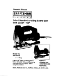
CRAFTSMAN CIRCULAR SAW - MODEL NUMBER 315.108620
,, ,,,,,,,,,,,,,,,,, ,,,,,,,,,,,,,,,,,,,
The
model
number
will be foundregarding
on a plate
to theSAW
motoror housing.
Alwaysrepair
mention
the model
number
in all
correspondence
yourattached
CIRCULAR
when ordedng
parts.
SEE BACK PAGE FOR PARTS ORDERING
J!
INSTRUCTIONS
=
, ,,,,,
,,,,,,,,,,,,,,,,,,,,,,,,,,,,,,,,,,,,,,,,,,,,,,,,,,,,,,
i
,,,,,
PARTS LIST
Key
O.
1
2
3
4
5
6
7
8
g
10
1t
12
13
14
15
16
17
18
19
2O
21
22
23
24
25
26
27
28
29
3O
3t
32
33
34
35
36
37
38
39
40
41
42
43
44
45
Part
Number
660124001
680776001
680775001
680774001
300516027
671985001
680778001
660312001
641111001
680769001
680767001
300003018
680022001
550631002
660198001
551008001
660180003
560844001
660822001
550423004
680771001
550266003
67O974OO1
66O824OO1
301271001
671704001
671705001
513109001
341110001
660113008
513108001
660426001
640940001
660212005
690500001
941011002
940005054
940266003
940267003
940006110
940057057
941012001
941011001
300053016
660434003
983000817
Description
*
°
*
*
°
*
*
*
*
*
Qty.
Blade Screw .....................................................................................................
1
Spring Washer .................................................................................................
1
Outer Blade Washer ("D" Washer) ....................................................................................................
1
Inner Flange Bushing .......................................................................................
1
Lower Blade Guard Assembly .........................................................................
1
Torsion Spring ..............................................................................................................................................
1
Retaining Ring .................................................................................................
1
Screw (8-32 x 3/8 in,) *'STD510803 ................................................................
3
Lower Guard Support ......................................................................................
1
Ball Bearing (6003LLB) .....................................................................................
1
Retaining Ring .................................................................................................
1
Gear Assembly ................................................................................................
1
Hex Nut (M4 x 3,2) ...........................................................................................
1
Vacuum Adapter Nozzle ....................................................................................................
1
Screw (6-32 x 3/8 in. Pan Hd.) "=STD600603 ..................................................
1
Vacuum Adapter ...............................................................................................
1
Screw (M5 x 32 mm) ............................................................................................. 1
Rubber Bumper ...............................................................................................
1
Carriage Bolt (1/4-20 x 98 ram) .......................................................................
1
Spacer .................................................................................................................
1
Washer ............................................................................................................
3
Knob ................................................................................................................
1
Lock Nut (M5) ............................................................................................................ 1
Pivot Bolt (M5 x 25 ram) ..................................................................................
1
Lever Assembly ........................................................................................................................................
1
E-Ring ....................................................................................................................... I
Hex Nut (t/4-20) ..............................................................................................
1
Pointer Bracket ................................................................................................
1
Pointer ...........................................................................................................................1
Screw (M2.6 x 4 ram) ......................................................................................
1
Knob .................................................................................................................
1
Carraige Bolt (1/4-20 x 28 mm) ............................................................................ 1
Bevel Bracket ..................................................................................................
1
Screw (M4 x 8 ram) .........................................................................................
1
Bumper Support ..................................................................................................
1
Rear Aperture Label ............................................................................................... 1
Logo Plate ........................................................................................................
1
Scale Label (Depth of Cut) ..............................................................................
1
Spindle Lock Label ..........................................................................................
1
Laser Warning Label .......................................................................................
!
Data Label ........................................................................................................
1
Pointer Scale Label .........................................................................................
1
Front Aperture Label .......................................................................................
I
Base Assembly .................................................................................................
1
Screw (M5 x 8 mm Hex Flat Head) .................................................................
4
Operator's Manual
* Standard Hardware Item - May Be Purchased Locally
** Available From Div, 98- Source 980.0
*** Complete assortment
available at your Nearest Sears Retail Store
24