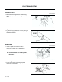
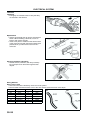
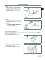
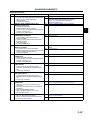
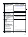
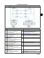
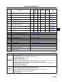
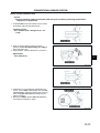
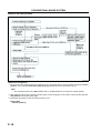
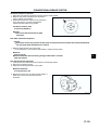
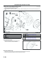
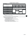
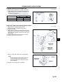
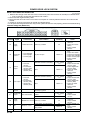
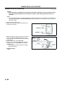
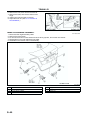
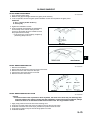
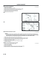
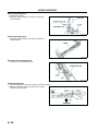
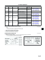
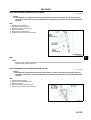
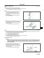
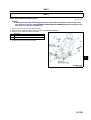
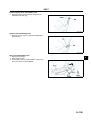
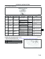
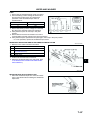
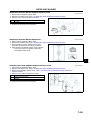
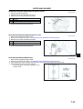
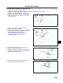
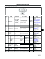
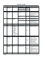
1
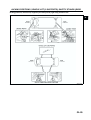
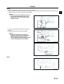
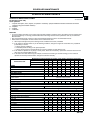
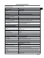
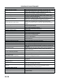
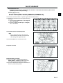
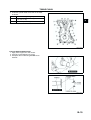
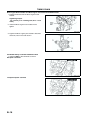
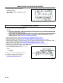
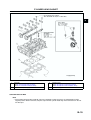
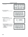
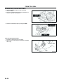
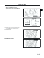
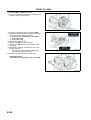
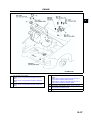
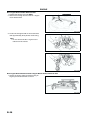
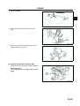
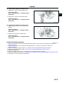
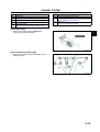
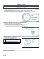
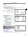
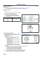
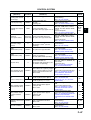
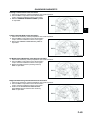
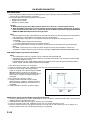
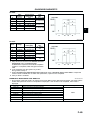
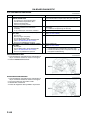
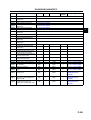
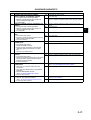
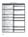
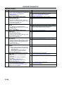
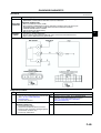
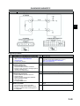
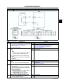
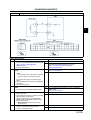
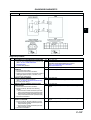
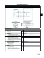
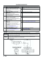
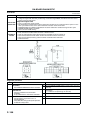
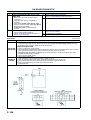
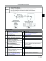
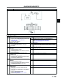
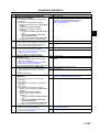
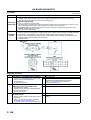
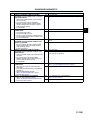
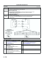
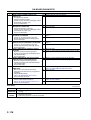
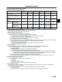
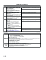
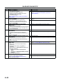
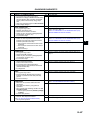
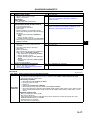
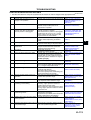
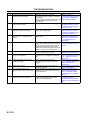
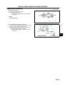
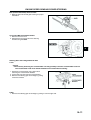
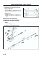
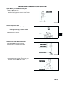
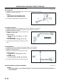
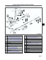
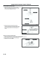
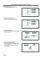
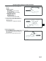
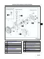
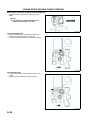
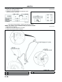
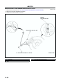
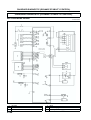
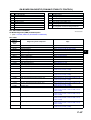
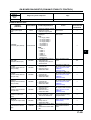
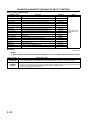
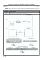
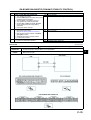
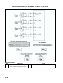
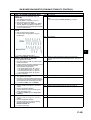
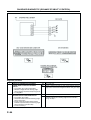
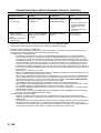
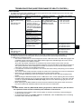
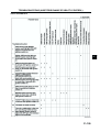
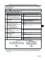
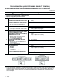
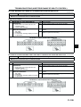
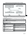
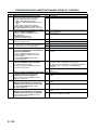
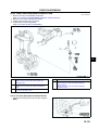
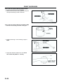
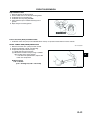
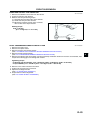
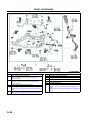
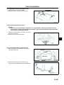
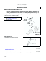
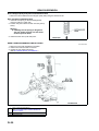
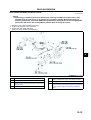
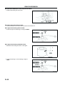
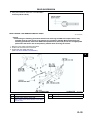
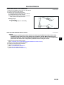
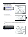
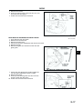
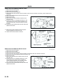
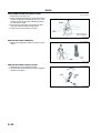
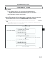
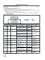
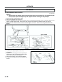
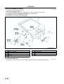
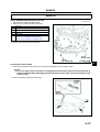
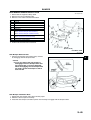
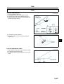
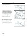
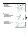
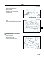
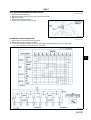
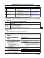
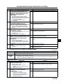
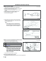
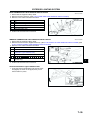
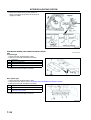
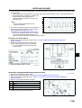
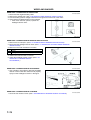
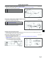
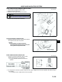
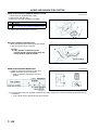
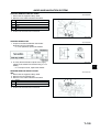
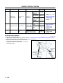
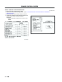
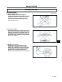
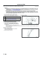
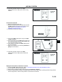
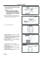
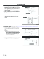
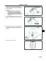
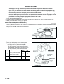
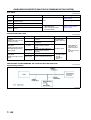
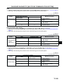
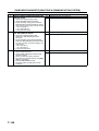
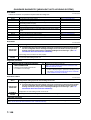
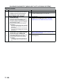
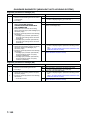
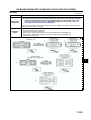
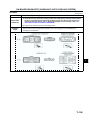
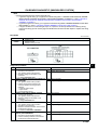
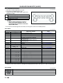
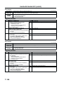
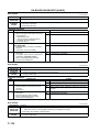
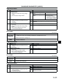
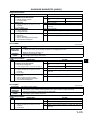
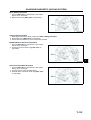
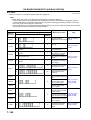
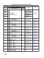
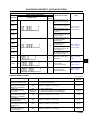
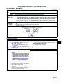
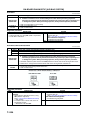
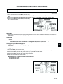
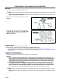
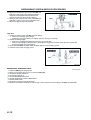
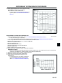
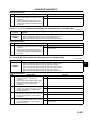
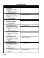
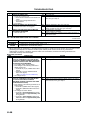
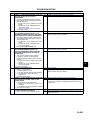
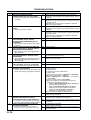
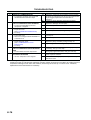
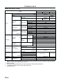
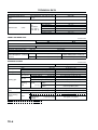
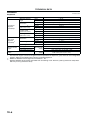
ON-BOARD DIAGNOSTIC STEP INSPECTION 4 INSPECT BRAKE SWITCH CONNECTOR FOR POOR CONNECTION • Turn ignition switch to OFF. • Disconnect brake switch connector. • Inspect for poor connection (damaged/pulledout terminals, corrosion, etc.). • Is there malfunction? 5 CLASSIFY BRAKE SWITCH OR CIRCUIT • Connect WDS or equivalent to DLC-2. • Access BOO PID. • Connect a jumper wire between brake switch terminal A and B. • Is BOO PID on? 6 INSPECT BRAKE SWITCH • Perform brake switch inspection. (See P8 BRAKE SWITCH INSPECTION.) • Is brake switch okay? 7 INSPECT BRAKE SWITCH POWER CIRCUIT FOR OPEN CIRCUIT • Measure voltage between brake switch connector terminal B and body ground. • Is voltage B+? 8 INSPECT PCM CONNECTOR FOR POOR CONNECTION • Turn ignition switch to OFF. • Disconnect PCM connector. • Inspect for poor connection (damaged/pulledout terminals, corrosion, etc.). • Is there malfunction? 9 INSPECT BRAKE SWITCH SIGNAL CIRCUIT FOR OPEN CIRCUIT • Inspect continuity between brake switch terminal D and PCM terminal 1K. • Is there any continuity? 10 INSPECT BRAKE SWITCH CONNECTOR FOR POOR CONNECTION • Turn ignition switch to OFF. • Disconnect brake switch connector. • Inspect for poor connection (damaged/pulledout terminals, corrosion, etc.). • Is there malfunction? 11 CLASSIFY BRAKE SWITCH OR CIRCUIT • Connect WDS or equivalent to DLC-2. • Access BOO PID. • Verify that BOO PID changes from ON to OFF when brake switch connector disconnected. • Does BOO PID change from ON to OFF? 12 INSPECT BRAKE SWITCH • Perform brake switch inspection. (See P8 BRAKE SWITCH INSPECTION.) • Is brake switch okay? 13 INSPECT BRAKE SWITCH SIGNAL CIRCUIT FOR SHORT TO POWER • Measure voltage between brake switch connector terminal D and body ground. • Is voltage B+? ACTION Yes Repair or replace terminal, then go to Step 14. No Go to next step. Yes Go to next step. No Go to Step 7. F Yes Go to Step 14. No Replace brake switch, then go to Step 14. Yes Go to next step. No Repair or replace brake switch power circuit for open, then Go to Step 14. Yes Repair or replace terminal, then go to Step 14. No Go to next step. Yes Repair or replace harness for open, then go to Step 14. No Go to Step 14. Yes Repair or replace terminal, then go to Step 14. No Go to next step. Yes Go to next step. No Go to Step 13. Yes Go to Step 14. No Replace brake switch, then go to Step 14. Yes Repair or replace harness for short to power, then go to Step 14. No Go to next step. F157