1
R
ESC
76
`~
0E
1!
16
TA B
0D
Keyboard
F1
05
F2
06
2@
1E
3#
26
Q
15
Caps Lock
58
Shift
12
W
1D
A
1C
F3
04
4$
25
E
24
S
1B
Z
1Z
Ctrl
14
F4
0C
X
22
F5
03
5%
2E
R
2D
D
23
6^
36
T
2C
F
2B
C
21
F6
0B
7&
3D
Y
35
G
34
V
2A
F7
83
8*
3E
U
3C
H
33
B
32
Alt
11
F8
0A
9(
46
I
43
J
3B
N
31
0)
45
O
44
K
42
M
3A
F10
09
-_
4E
=+
55
P
4D
L
4B
,<
41
F9
01
[{
54
;:
4C
>.
49
Space
29
'"
52
/?
4A
Alt
E0 11
F11
78
F12
07
E0 75
Back Space
E0 74
66
]}
5B
\|
5D
E0 6B
Enter
5A
E0 72
Shift
59
Ctrl
E0 14
UG230_c8_03_021806
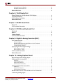
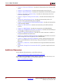
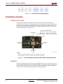
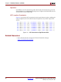
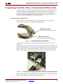
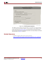
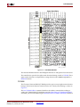
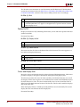
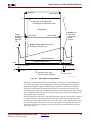
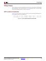
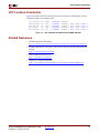
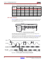
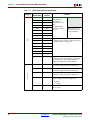
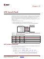
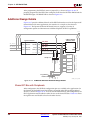
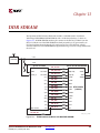
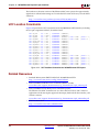
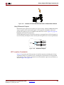
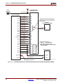
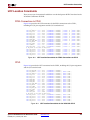
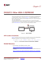
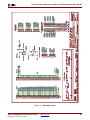
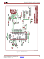
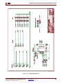
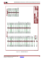
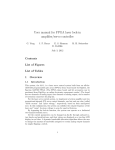
Figure 8-3:
PS/2 Keyboard Scan Codes
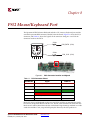
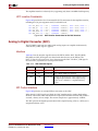
The host can also send commands and data to the keyboard. Table 8-3 provides a short list
of some often-used commands.
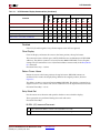
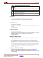
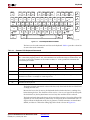
Table 8-3:
Common PS/2 Keyboard Commands
Command
Description
ED
Turn on/off Num Lock, Caps Lock, and Scroll Lock LEDs. The keyboard acknowledges receipt of an
“ED” command by replying with an “FA”, after which the host sends another byte to set LED status. The
bit positions for the keyboard LEDs are shown below. Write a ‘1’ to the specific bit to illuminate the
associated keyboard LED.
7
6
5
4
Ignored
3
2
1
0
Caps Lock
Num Lock
Scroll Lock
EE
Echo. Upon receiving an echo command, the keyboard replies with the same scan code “EE”.
F3
Set scan code repeat rate. The keyboard acknowledges receipt of an “F3” by returning an “FA”, after
which the host sends a second byte to set the repeat rate.
FE
Resend. Upon receiving a resend command, the keyboard resends the last scan code sent.
FF
Reset. Resets the keyboard.
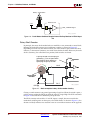
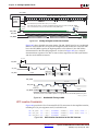
The keyboard sends commands or data to the host only when both the data and clock lines
are High, the Idle state.
Because the host is the bus master, the keyboard checks whether the host is sending data
before driving the bus. The clock line can be used as a clear to send signal. If the host pulls
the clock line Low, the keyboard must not send any data until the clock is released.
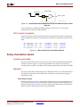
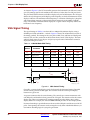
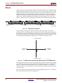
The keyboard sends data to the host in 11-bit words that contain a ‘0’ start bit, followed by
eight bits of scan code (LSB first), followed by an odd parity bit and terminated with a ‘1’
stop bit. When the keyboard sends data, it generates 11 clock transitions at around 20 to
30 kHz, and data is valid on the falling edge of the clock as shown in Figure 8-2.
Spartan-3E FPGA Starter Kit Board User Guide
UG230 (v1.2) January 20, 2011
www.xilinx.com
65


![2008 [DAMN SMALL NAS]](http://vs1.manualzilla.com/store/data/005757702_2-ad0d2f1082977ee9ed587e807bbc0127-150x150.png)