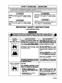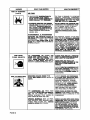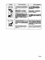
1
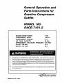
General Operation and
Parts Instructions for
Gasoline
Outfits
Compressor
MODEL NO.
DACE-7161-2
ENGINE HORSE POWER
COMPRESSOR
BORE
COMPRESSOR
STROKE
AIR TANK CAPACITY
APPROXIMATE
SCFM
SCFM
e
This
product
UNLOADER
11liP
PRESSURE
@ 100 psig
@ 175 Psig
is not equipped
with
1.96/4.3
2.17
30 GAL.
175 PSIG
12.5
12,0
a spark
arresting
muffler.
If the product
will be used around
flammable materials, or on land covered with materials such asagricultural crops, forest, brush,grass, or other similar
items, then an approved spark arrester must be installed and is legally required in the state of California. It is a
violation of California statutes section 130050 and/or sections 4442 and 4443 of the California Public Resources
Code, unless the engine is equipped with a spark arrestor, as defined in section 4442, and maintained in effective
working order. Spark arresters are also required on some U. S. Forest service land and may also be legally required
under other statutesand ordinances.
e
Engine exhaust from this product containschemicalsknown, in certain quantities,to causecancer,birth defects or
other reproductive harm.
J_,V//.B/SS
_13
MGP-DAC-7161-2A
7/9/99
A/R
_
Indus_lal
€_O/ImulqJIIY
Dr. • Jacb_n,
TN
38301
TABLE OF CONTENTS
Page No.
SAFETY PRECAUTIONS ...................................................................................
3-5
GENERAL INFORMATION ....................................................................................
6
COMPRESSOR DIAGRAM ...................................................................................
7
DESCRIPTION OF OPERATION .........................................................................
6
INSTALLATION ................................................................................................
8-10
Pre-lnstallationInspection................................................................................
8
Vibration Mounting Kit (StationaryCompressor Outfits).................................... 8
Location of the Compressor Outfit ................................................................ 8-9
Air Line Piping(Stationary Compressor Outfits) ........................................... 9-10
OPERATION ...................................................................................................
11-14
Operator Controls .....................................................................................
11-12
Daily Startup Procedures ..........................................................................
13-14
Break-In Procedures.......................................................................................
13
MAINTENANCE .............................................................................................
14-17
Routine Maintenance Schedule ......................................................................
14
Cleaning the Air Compressor Outfit ................................................................. 15
Checking and Changing Oil ............................................................................
16
Checking and Changing Air Intake Filter.......................................................... 16
DrainingWater from Air Tank ...........................................................................
16
Checking and Adjusting Belt Tension.............................................................. 17
SERVICE INSTRUCTIONS ............................................................................
17-19
Replacing Drive Belt .................................................................................
17-18
Engine Pulleyand Flywheel Alignment ............................................................ 18
Check Valve Inspection and Cleaning ....................................................... 18-19
Servicing Intake and Exhaust Valves .............................................................. 19
TROUBLESHOOTING GUIDE .......................................................................
Air Compressor Diagram & Parts List ........................................................
Compressor Pump Diagram & Parts List...................................................
20-24
26-27
28-29
WARRANTY .........................................................................................................
30
SERVICE NOTES ..................................................................................................
31
ORDERING REPAIR PARTS ................................................................................
32
PAGE 2
SAFETY
GUIDELINES
- DEFINITIONS
This manual contains information
that is important for you to know and understand.
This information
relates to protect
ing YOUR SAFETY and PREVENTING
EQUIPMENT
PROBLEMS.
To help you recognize this information,
we use th_
symbols to the right. Please read the manual and pay attention to these sections.
I Jk DANGER
IA
I
DANGER
indicates an imminently hazardous situation
which, if not avoided, will result in death or serious
CAUTION
CAUTION
indicates a potentially
which, if not avoided,
I
hazardous situation
may result in minor
or moder-
injury.
I _WARNING
I
WARNING
indicates a potentially hazardous situation
which, if not avoided, could result in death or serious
injury.
IMPORTANT
•
I CAUTION
I
CAUTION used without the safety alert symbol indicates a potentially hazardous situation which, if net
avoided, may result in _roDertv damaae.
SAFETY INSTRUCTIONS
SAVE THESE INSTRUCTIONS
,
IMPROPER OPERATION OR MAINTENANCE OF THIS PRODUCT COULD RESULT
IN SERIOUS INJURY AND PROPERTY DAMAGE. READ AND UNDERSTAND ALL
WARNINGS AND OPERATING INSTRUCTIONS BEFORE USING THIS EQUIPMENT,
WHAT CAN HAPPEN
HAZARD
RISK OF
EXPLOSION OR FIRE
HOW TO PREVENT IT
GASOUNE
AND GASOLINE VAPORS CAN
BY COMING INTO CONTACT WITH HOT COMPONENTS SUCH AS
THE MUFFLER,
GASES, OR FROM AN ELECTRICAL SPARK.
TURN ENGINE OFF AND ALLOW IT TO
COOL BEFORE ADDING FUEL TO THE
TANK. EQUIP AREA OF OPERATION WITH
A FIRE EXTINGUISHER CERTIFIED TO
HANDLE GASOLINE OR FUEL FIRES.
COMBUSTIBLE
MATERIALS WHICH COME
INTO CONTACT WITH
HOT ENGINE PARTS
CAN BECOME IGNITED.
ADD FUEL OUTDOORS OR IN A WELL
VENTILATED AREA. MAKE SURE THERE
ARE NO SOURCES OF IGNITION, SUCH AS
CIGARETTES NEAR REFUELING LOCATION.
OPERATE
COMPRESSOR
IN AN OPEN
AREA AWAY FROM DRY BRUSH, WEEDS
OR OTHER COMBUSTIBLE
MATERIALS.
STORE FUEL IN A SECURE
AWAY FROM COMPRESSOR.
UNATTENDED OPERATION OF THIS PRODUCT COULD RESULT IN PERSONAL INJURY
RISK OF BURSTING
LOCATION
ALWAYS REMAIN IN A'FrENDANCE WITH
THE PRODUCT WHEN IT IS OPERATING.
AIR TANK
THE
FOLLOWING
CONDITIONS
COULD
LEAD TO A WEAKENING OF THE TANK, AND
RESULT IN A VIOLENT TANK EXPLOSION:
1. FAILURE TO PROPERLY DRAIN
CONDENSED
CAUSING RUST AND THINNING OF THE
STEEL TANK.
DRAIN TANK DAILY OR AFTER EACH
USE.
IF TANK DEVELOPS A LEAK,
REPLACE IT IMMEDIATELY WITH A NEW
TANK OR NEW COMPRESSOR OUTFIT.
2. MODIFICATIONS
REPAIRS
NEVER DRILL INTO, WELD, OR MAKE _Y
MODIFICATIONS
TO THE TANK OR ITS
ATTACHMENTS.
OR A'I-FEMPTED
PAGE 3
HAZARD
RISK
WHAT CAN HAPPEN
HOW TO PREVENT IT
OF BURSTING
AIR TANK
(cont'd)
3. UNAUTHORIZED MODIFICATIONS
TO
THE UNLOADER VALVE. SAFETy
VALVE. OR ANy
WHICH CONTROL TANK
THE TANK IS DESIGNED TO WITHSTAND
SPECIFIC
OPERATING
PRESSURES.
NEVER MAKE ADJUSTMENTS
OR PART(;
SUBSTITUTIONS
TO ALTER THE FACTORY SET OPERATING
4. EXCESSIVE
DO NOT REMOVE THE STIFFENER BAR
CONNECTING THE COMPRESSOR PUMP
TO THE ENGINE, EXCEPT TO ADJUST
BELT TENSION, THEN SECURELY
TIGHTEN THE STIFFNER BAR NUTS.
THIS BAR CONTROLS OUTFIT VIBRA-
VIBRATION CAN WEAKEN
AND CAUSE RUPTURE OR
EXPLOSION.
WILL OCCUR IF THE COMPRESSOR 18
OR IF THE
ENGINE OPERATES ABOVE RECOMMENDED RPM.
ATTACHMENTS
RISK FROM
FLYING OBJECTS
I
T1ON.
& ACCESSORIES
EXCEEDING
THE PRESSURE RATING OF
_R TOOLS. SPRAY GUNS, AIR OPERATED
ACCESSORIES,
TIRES
AND
OTHER
INFLATABLES
T
XPLODE OR FLY APART, AND COULD RESULT
IN SERIOUS INJURY.
FOR ESSENTIAL CONTROL OF AIR PRESSURE, YOU MUST
REGULATOR
AND PRESSURE
GAUGE
OF YOUR COMPRESSOR. FOLLOW THE EQUIPMENT MANUFACTURERS
RECOMMENDATION
AND
NEVER EXCEED THE MAXIMUM ALLOWABLE PRESSURE RATING OF A1TACHMENTS. NEVER USE COMPRESSOR
TO
INFLATE SMALL
LOW-PRESSURE
OmlJECTS SUCH AS CHILDREN'S
TOYS.
FOOTBALLS. BASKETBALLS.
ETC.
THE _
STREAM
CAN
CAUSE SOFT TISSUE
DAMAGE TO EXPOSED SKIN AND CAN PROPEL DIRT,
CHIPS, _
AND SMALL
OBJECTS AT _
RESULTING IN
PROPERTY DAMAGE OR PERSONAL INJURY.
ALWAYS WEAR ANSI Z87.1 APPROVED
SAFETY GLASSES WITH SIDE SHIELDS
WHEN USING THE COMPRESSOR.
NEVER POINT ANY NOZZLE OR
SPRAYER TOWARD ANY PART OF THE
BODY OR AT OTHER PEOPLE OR
ANIMALS.
ALWAYS TURN THE COMPRESSOR OFF
FROM THE AIR
HOSE AND TANK BEFORE ATTEMPTING
MAINTENANCE, AI"rACHING TOOLS OR
ACCESSORIES.
RISK TO BREATHING
BREATHING
ENGINE _
EXHAUST
FUMES FROM
SERIOUS INJURY OR
DEATH.
THE
COMPRESSED
AIR
FROM
YOUR
COMPRESSOR
THE AIR STREAM
MAY CONTAIN
CARBON MONOXIDE, TOXIC VAPORS OR
SOLID PARTICLES FROM THE TANK.
SUCH AS PAINT,
PAINT SOLVENTS, PAINT REMOVER, INSECTICIDES, WEED KILLERS, ETC.. CONTAIN
HARMFUL VAPORS AND POISONS.
PAGE 4
ALWAYS OPERATE AIR COMPRESSOR
IN A CLEAN. WELL VENTILATED AREA.
AVOID ENCLOSED AREAS SUCH AS
GARAGES, BASEMENTS, STORAGE
SHEDS, ETC., WHICH LACK A STEADY
EXCHANGE OF AIR.
UNIT IN ENCLOSED LOCATIONS
OCCUPIED BY HUMANS OR ANIMALS.
KEEP CHILDREN, PETS AND OTHERS
AWAY FROM AREA OF OPERATION.
NEVER INHALE AIR FROM THE COMPRESSOR EITHER DIRECTLY OR FROM A
BREATHING DEVICE CONNECTED TO THE
COMPRESSOR.
WORK IN AN AREA WITH GOOD CROSSREAD AND
PROVIDE ON
THE LABEL OR SAFETY DATA SHEETS
FOR THE MATERIAL YOU ARE SPRAYING.
USE A NIOSH/MSHA APPROVED
DESIGNED FOR USE WITH
YOUR SPECIFIC APPLICATION.
HAZARD
WHAT CAN HAPPEN
RISK FROM
MOVING PARTS
i
RISK OF BURNS
HOW TO PREVENT IT
THE ENGINE CAN START ACCIDENTALLY
IF THE FLYWHEEL IS TURNED BY HAND OR
MOVED BY PULLING ON THE STARTER
ROPE.
ALWAYS
SP
PLUG AND BLEED PRESSURE FROM
THE TANK BEFORE PERFORMING
MAINTENANCE.
MOVING PARTS SUCH AS THE PULLEY,
FLYWHEEL AND BELT CAN CAUSE
IF THEY COME INTO
CONTACT WITH YOU OR YOUR CLOTHING.
NEVER OPERATE THE_
W_H GUARDS OR COVERS WHICH ARE
DAMAGED OR REMOVED.
_L_
COMPRESSOR WITH DAMAGED OR MISSING PANTS
OR AI"rEMPTINO
TO REPAIR COMPRESSOR WITH PROTECllVE
SHROUDS
REMOVED CAN EXPOSE YOU TO MOVING
PAR_ AND DAN RESULT IN SERIOUS
INJURY.
ANY REPAIRS REQUIRED ON THIS PRODUCT
SHOULD
BE PERFORMED
BY
AUTHORIZED
SERVICE
CENTER PERSONNEL.
TOUCHING EXPOSED METAL SUCH AS THE
COMPRESSOR HEAD OR OUTLET TUBES OR
CONTACT WITH HOT ENGINE PARTS SUCH
AS THE MUFFLER _J_L_I_,T_U_J_
BURNS.
NEVER TOUCH ANY EXPOSED METAL
PANTS ON ENGINE OR COMPRESSOR
DURING OR IMMEDIATELY AFTER OPERATION. ENGINE AND COMPRESSOR WILL
REMAIN
HOT FOR SEVERAL MINUTES
AFTER OPERATION.
THE GASOLINE ENGINE, THE ENGINE
MUFFLER, THE COMPRESSOR HEAD AND
TUBING BECOME VERY HOT DURING
OPERATION.
DO NOT REACH AROUND PROTECTIVE
SHROUDS OR A'I-rEMPT MAINTENANCE
UNTIL UNIT HAS BEEN ALLOWED TO COOL.
PAGE 5
GENERAL
You have pumhaeed a complete compressoroutfit consistingof an air compressor, ASME approved air tank,
gasoline engine, and associated controls and instruments. The compressor outfit you have selected is a
two stage stationary outfit.
Your new compressor can be used for operating paint
sprayers, air tools, grease guns, air brushes, caulking
guns, and sand blasters, spraying weed killer and
insecticides, etc. An air pressure regulator may be
necessary for some of these
DESCRIPTION
The gasoline engine uses a pulley and drive belt to
drive the compressor flywheel. The flywheel turns the
compressor crankshaft causing the up and down movement of the pistons in the cylinder; this up and down
movement draws and compresses the air.
On the down strokeofthe piston,air isdrawn inthrough
the air intake. The exhaust valves remain closed. On
the up stroke of the piston, both the valves are closed
and air is compressed in the cylinder. As pressure
builds in the cylinderthe exhaust valveopens and the
compressed air is forced out of the cylinder through
the check valve and into the air tank. This process
continuesuntilthe air pressure reaches maximum tank
pressure.
Working air pressure becomes availablewhen the compressor has raised the tank pressure above that required at the air discharge valve. The air intake must
be kept clear of all obstructions which could interfere
with air delivery to the compressor.
All gasoline compressor outfits are continuously running outfits controlled bytank pressure. At maximum
PAGE 6
INFORMATION
applications. Refer to Figure 1 for a photograph of
the compressorand to identifythe majorcomponents
of the compressor.
A regularly scheduled program of preventive maintenance is necessaryto insurethe long lifethat has been
designed into your DeVilbiss compressor outfit. This
instruction manual, along with regular maintenance
will maintain your compressor outfit in good working
order.Beforeoperatingor performingany maintenance
on your outfit, refer to these publications.
OF OPERATION
tank pressure the unloader valve exhausts air to atmosphere (blowoff); tank pressure closes the check
valve retainingair pressure inside the tank. When tank
pressure drops to a pre-determined pressu,=, ;3,=
unloader valve closes, and air pressure opens the
check valve allowing compressed air into the tank. As
maximum tank pressure is reached, if the unloader
valve malfunctions and compressed air is not exhaustedat or near its blowoff setting,the air tank safety
valve wilt protect the air tank against high pressure by
popping at its factory set pressure. The safety valve
popping pressure is slightly higher than the unloader
valve blowoff pressure.
This compressor outfit is equipped with a gas saving
throttle controldevice. When maximum tank pressure
is reached and the unloader valve opens the throttle
control is also activated, The throttle control holdsthe
engine at a factory set idling speed until air pressure
in the tank drops to reset or minimum tank pressure.
At reset pressure when the unloader valve closes the
throttle control is reactivated and the engine accelerates to full throttle.
Pump
Air Intake
Gas
Engine Oil
Dipstick
Engine
Filter
Belt
Guard
Fuel
Tank
Two-Stage
Pump
Engine Air
Filter
Pump Oil
Fill Plug
Engine Oil
Drain
(Not Shown)
Throttle
Control
Pump Oil
Sight Glass
Oil
Drain Plug
PressureGauge
Drain Valve
(Not Shown)
Figure I- Typical Gasoline
Air Outlet For
Discharge
Valve
Compressor
Outfit
PAGE 7
INSTALLATION
PRE-INSTALLATION
INSPECTION
NOTE
Each air compressor outfit is carefully checked before shipment. With
improper handling, damage may
result in transit and cause problems
in compressor operation; a bent
crankshaft, etc.
2.
Insertthevibration mountsin the mountingholes.
Place a fiat washer under the mounting surface
and secure each mount with a Iockwasher and
nut. See Figure 3.
Immediatelyon equipmentarrival,checkfor both concealed and visibledamages to avoid expenses being
incurred to correctsuch problems.This shouldbe done
regardlessof any visible signsof damage to the shipping container.Report any damages to carrier and arrange for inspectionof goods immediately.
VIBRATION MOUNTING
(Stationary Compressor
KIT
Outfits)
LOCKWASHER
Figura3-1nstallation
Bolting legs to a stiff surface can
cause tank rupture resulting in serious
injury or damage. Do not permanently
mount compressor to any surface without using the vibration mount kit.
Portable compressor outfits may be permanently
mounted in one location such as a truck bed, if desired. A vibration mount kit is included with the outfit
for this purpose.
1. In order to maintain adequate ventilation for
compressor cooling and to avoid contact with
pick-up truck bed, always mount the outfit at
least 8 inches from any vertical wall. Using the
holes in the airtank support legs as a guide,
mark and drill four 5/16 inch diameter holes in
the mounting surface.
To prevent excessive vibration which
may cause tank rupture or explosion,
never remove the engine stiffener bar
or increase the engine RPM. Make
sure the engine bolts and stiffener bar
nuts are tight. Do not operate the outfit
if the rubber feet are not attached.
PAGE 8
NUT
of Vibration Mounting
Kit
3. Set the outfiton top of the vibration mounts
(the exposed threaded ends) and secure
each mount to the air tank legs with lock
washer and nut.
LOCATION OF THE COMPRESSOR
OUTFIT
Engine exhaust contains toxic carbon
monoxide. Operate the engine in a well
ventilated area only. If inhaled, it can
cause dizziness, unconsciousness and
possibly death.
The air compressoroutfitshould be located as close
as possibleto the pointwhere the compressed air is
to be used. The area selected should be dry, clean,
cool, and well ventilated. Make certain that the outfit
is mounted level on a solidfoundation so no strain is
imposed on the supportfeet or base. Keep the outfit
away from areas which have dirt, vapor,and volatile
fumes in the atmosphere which may clogand gum
the intakefilterand valves causing inefficient
operation. Where this not practicala remote air
intake is recommended.
NOTE
Where a remote air intake is used, enlarge
the side of the air intake piping by one pipe
size for each t0 feet of length.
Stationary outfits must be bolted or lagged to the floor
to prevent movement. When lagging down, leave a minimum of 1/8 inch between the bolt and support feet.
The use of vibration pads at each support foot is req uired to eliminate the possibility of tank rupture.
The flywheel side of the outfitshouldbe placed toward
the wall and protected with a totally enclosed belt
guard. In no case should the flywheel be closer than
12 to 18 inches from the wall or other obstruction that
will interfere with the flow of air through the fan blade
flywheel. See Table 1 for recommended distances. The
area should allow space on all sides for air circulation
and for ease of normal maintenance.
The compressor outfit must not be operated in any confined area
where
heat from the outfit can not readily escape. Damage to the outfit may result.
Pipe thread sealant must be used on all threads, and
all joints are to be made up tight, since small leaks in
the pipingsystem are the largestsingle cause of high
operating costs.
All piping should be sloped to an accessible drain
point and all outlets should be taken from the top of
the main distributionair line so that moisture cannot
enter the outlet.
The main distribution air line should not be smaller
than the compressorair dischargevalve outlet.A
smaller line will restrictthe flow of air. For long air
lines, refer to Table 2, Pipe Sizes for Compressed
Air Lines, for recommended pipe sizes. It is recommended that a flexible couplingbe installedbetween
the air dischargevalve outlet and main air distribution lineto allowfor vibration.
To remove entrained dirt, oil and water, installseparator in the main distribution line, a sufficient distance
from the compressor.This will allowthe air to cool to
room temperature before passing through the separator.
Additional separators or filter may be used depending on the application.
NOTE
The compressor crankcase and head are designed
with fins which allow for proper cooling. Clean or blow
offthe fins and any other parts of the compressor outfit that collect dust or dirt. A clean compressor runs
cooler and provides longer service. Do not place rags,
containers, or other matedal in or against the belt guard
which will obstruct ventilation openings necessary for
For underground installation, bury air
lines below the frost line and avoid
pockets where condensation
can
gather and freeze. Apply pressure before underground lines are covered
to make sure all pipe joints are free
from leaks.
proper compressor operating temperatures.
AIR LINE
PIPING
(STATIONARY
COMPRESSOR
OUTFITS)
Table 2 Pipe Sizes for Compressed Air Lines
AIR
cfm
The use of plastic pipe, soldered joint,
or failure to insure system capability
of flex joints and flexible hose can
result in mechanical failure, property
damage, and serious injury.
Plastic or PVC pipe is not designed for
usewith compressed air. Regardless
of its indicated pressure rating, plastic
pipe can burst from air pressure. Use
only metal pipe for air distribution lines.
A typical compressedair distribution system as shown
in Figu re 4, page 10 should be of sufficientpipe size
to keep the pressure drop between the supply and
point of use to a minimum. All pipes and fittings used
must be certified safe for the pressures involved.
LENGTH OF PIPE LINES IN FEET
25
50
75
100
150
1-5
1/2 1/2
1/2 1/2
1/2
10
1/2 1/2
1/2 1/2
1/2
15
1/2 3/4
3/4 3/4
3/4
20
3/4 3/4
3/4 3/4
3/4
25
3/4 3/4
3/4 3/4
1
30
3/4 3/4
3/4
1
1
35
3/4 3/4
1
1
1
40
3/4
1
1
1
50
1
1
1
1
1
60-70 1
1
1
1
1-1A
80-100 1-IA 1-I/_ I-I,_I-1/_I-Ih
200 250 300
1/2 1/2 142
1/2 1/2 142
3/4 3/4 3/4
3/4 3/4 3/4
1
1
1
1
1
1
1
1
1
1
1
1
1
1
1
1-1/ 1-1A 1-_A
1-Y.,
1-V21-I/2
Pipe sizes are in inches
PAGE 9
FEEDER LINES
SLOPEWITH
AIR FLOW
AIR FLOW \
AIR FLOW
_r--_
MAIN DISTRIBUTION
AIR LINES
SLOPE PIPE IN DIRECTION
OF AIR FLOW.
WATER CONDENSATE FLOWS
ALONG So'PrOM OF PIPE TO
DRAIN LEGS, PREVENTING IT
FROM ENTERING FEEDER
LINES.
REGULATOR
AIR
USAGE
LEGS
/N
LUBRICATOR
OF
TRAP
DRAIN
TRAPS
FILTER
MOISTURE SEPARATOR
AND TRAP
FLEXIBLE
COUPLING
AIR DISCHARGE
VALVE
COCK
VALVE
VIBRATION
Figure 4. Typical Compressed
PAGE 10
Air Distribution
PADS
System
OPERATION
Operator Controls
The unloader valve for the operation of the gasoline
compressor outfit is located between the compressor
pump and gasoline engine. The air discharge valve
can be located on the end of the air tank. The safety
valve and pressure gauge are attached to the tank
below the unloader. See page 7.
Unloader
Valve
Pressure loads beyond the design limits
may cause tank rupture or explosion. Do
not attempt to adjust, remove, or defeat
the unloader valve, or change and modify
any pressure control device. If replacement is necessary, the same rated valve
must be used.
The unloader valve, Figure 6, iscontrolledbytank pressure. Compressors with unloaders run continuously
and maintain air pressure within set limits. At maximumtank pressurethe unloadervalve opens and the
compressed air is exhausted to atmosphere. This
preventsthecompressorfrom continuallybuildingmore
pressure if air is not needed. When the tank pressure
drops to a predetermined minimum pressure, the
unloadervalveclosesand the compressoragainbuilds
up the tank pressure. Pressure continuesto builduntil maximum tank pressure is achieved. The cycle
then repeats itself.
The unloader isused because frequent start-upsand
stops are impractical with a gasoline engine. The
unloadervalve is preset at thefactory. Never attempt
to make adjustments to the unloader valve.
The toggle leveron thefront of the unloader valve should
be pulled out or in the horizontalposition when starting up the compressor. This prevents the compressor
from starting under load. Once the engine has reached
full throttle, the lever should be pushed to the side,
returning it to its original position to allow the compressor pump to build pressure in the air tank.
Toggle
Lever
Figure 6. Unloader Valve
PAGE 11
The unloaderthen reactivates the throttle control
and accelerates the engine to fullthrottle.
Over-pressurization of the air tank
may cause tank rupture or explosion.
The air tank is protected from overpressurization by a safety valve. Do
not eliminate, make adjustments or
substitutions to this device. Occasionally pull the ring on the safety valve
to make sure it operates freely. If it
doesn't, the safety valve must be
replaced. Innercooler safety valves
used on two stage outfits must be
similarly checked.
The safety valve, Figure 7, is set at the factory to be
pressure approximately 15 pounds higher than the
rated pressure of the outfit. Ifthe unloader valve malfunctions and does not exhaust compressed air automatically at maximum tank pressure the safety valve
willprotectthe air tank againstexcessive air pressure
by poppingoff at its preset pressure.
Two stagecompressorswith unloadercontrolswillhave
a safety valve on the intercooler, set 50 to 55 pounds.
The purpose of this safety valve is to prevent the full
tank pressure building up in the large, low pressure
cylinderor intercooler.
THRO'I-rLE
ADDITIONAL
CONTROLS
REGULATORS
AND
Since the air tank pressure is usually greater than
that which is needed, a separate regulator is usually
employed to controlthe air pressure ahead of any
individualair drivendevice.
The gasoline engine and air compressor
pumps on all compressor outfits are
shipped without oil Do not attempt to
operate for any reason without first adding oil to the engine and compressor
pump crankcase. Serious damage can
result from even very limited operation
unless filled with oil and broken in
correctly. Make sure to closely follow the
initial startup procedures.
NOTE
The compressor outfit should be placed
on a level surface in a dry, clean, well
ventilated, area. Do not place any material on or against the belt guard. This
blocks ventilator openings necessary for
proper compressor cooling.
CONTROL
A gas saving throttle control has been incorporated
on somecompressor outfits.Duringnormaloperation,
as maximum tank pressure is obtained, the unloader
exhausts compressed air and activates the throttle
control of the engine. The throttle control holds the
engine at a factory set idling speed until air pressure
in the tank drops to reset or minimum tank pressure.
1. Remove the oilfill plugson the gasoline engine
and air compressorpump and slowly add oil
until the unitsare full. Refer to the "Gasoline
Engine Owners Manual"for recommended oils
and fill capacitiesfor the engine. The compressor pump holds approximately 60 fluid oz..
TWO STAGE COMPRESSOR
UNITS
Viscosity Chart
Figure 7. Safety Valve
Recommended Oil
(API SG/CD Heavy Duty]
Room or Ambient
Temperature
SAE20
SAE30
Below 20°F
Above 32°F
Crankcase
capacity equals approximately
ounces,
60 fluid
2. The air compressor outfitis readyforuse.
PAGE 12
3. Periodicallycheck the compressoroutfitduring
the first few days of operation to make sure
the compressor outfit is runningsmoothly and
all controlsare operating properly.
NOTE
After the compressor has been in
operation for 2 to 3 hours, tighten the
compressor head bolts.
Torque two stage compressor head
bolts to 35 foot-pounds using a crisscross pattern when tightening.
BREAK-IN
PROCEDURES
4. Check the engine fuel tank level.Add fuel if
necessary.
Before starting the compressor outfit, check the
following:
.
Move the control lever orchoke lever tothe
CHOKE position.
7,
8. Turn the engine lever or key switch to the
ON position.
NOTE
If the engine is warm or the air temperature is high, move the control
lever or choke lever away from the
CHOKE position as soon as the engine
starts.
Perform steps 1-8 of the Daily StartupProcedures.
Open the air dischargevalve.
DALLY
STARTUP
PROCEDURES
.
Performthe followingchecks beforestartingthe
compressoroutfit.
1. Ensurethat nothing is blocking the belt
guard air openings.
2. Pullthe dng on the safety valve to make
sure the valve moves freely and smoothly.
Close the air dischargevalve.
6. Set the toggle lever of the unloadervalve in
the vertical positionto relieve compressor
head pressure.
Start the compressor outfit by pulling the
starter handle or by depressing the starter
button.Return the toggle lever on the unloader
valve to the horizontal positionand allow
outfitrunfor 10 minutes without buildingany
pressure. Check that the unloader exhausts
air at maximum tank pressure.
3. Check the engine and compressoroil levels.
Add oil if necessary.
If these break-in procedures are not
followed, premature pump failure may
result and void your warranty.
Gasoline is extremely flammable and
explosive. Refuel in a well ventilated
area with engine stopped. Allow engine
to cool before refueling.
10.Check the following:
a.
Do not smoke or allow flames or sparks in
the area where the engine is refueled or
where gasoline is stored.
Do not overfill the tank and make sure
the filler cap is securely closed after
refueling. Be careful not to spill fuel
when refueling. Fuel vapor or spilled
fuel may ignite. If any fuel is spilled,
make sure the area is dry before
starting the engine.
b.
Make sure all controlsare operating
correctly.Refer to the "Operator Controls"
section of this manual. A separate
gasoline engine instructionmanual is
provideddetailingengineoperation.
Check all air lines, fittings and pipes for
leaks. Even minor leaks can cause the
compressorto overwork resultingin
prematurebreakdown or unsatisfactory
performance.
PAGE 13
c. Check for excessive vibration and noise.
Correct any defects found.
d.
Turn the engine lever or key switchto the OFF
position.
2,
Check for oil leaks. Correct any leaks
found.
Close the air dischargevalve.
.
4.
SHUT DOWN
PROCEDURES
To stop the engine in an emergency, turn the engine
ON/OFF lever or key switch to the OFF position.Under normal conditions,use the following procedures.
Remove air tool or accessory.
5. Open outlet valve or regulator to allow air to
slowly bleed from the tank. Close the outlet
valve or regulator when the tank pressure is
approximately20 psig.
6.
Drainwater from tank.
1. Allow the tank pressure to buildto maximum
and the engine to throttle downto idle speed.
MAINTENANCE
To ensure efficientoperation and longer life of the air
compressor outfit a routine maintenance schedule
shouldbe prepared and followed. The followingroutine maintenance schedule is geared to an outfitin a
normalworkingenvironment operating on a daily basis. If necessary, the schedule should be modifiedto
suitthe conditionsfound with your compressoroutfit.
The modificationswill depend upon the hours of operation and the working environment. Compressor
outfitsin an extremelydirtyand/orhostileenvironment
will require a greater frequency of all maintenance
checks. The maintenance label mounted on the air
tank also liststhe required maintenance checks.
NOTE
Drain and refill the compressor pump
crankcase after the first 100 hours of
operation. Add approximately 60 oz..
to pump.
Drain and refill the gasoline engine crankcase
after the first 20 hours of operation. See "Gasoline
Engine Owners Manual" for engine crankcase
capacity.
2.
Drain water from the air tank and any
moisture separators or trensformers.
3. Check for any unusual noiseand/or vibration.
Foradditionalmaintenanceinstructions,recommended
oil and fuel on the gasoline engine, refer to "Gasoline
Engine Owners Manual".
4.
Check the conditionof the air cleaner on the
gasoline engine. Clean and/or replace as
necessary.
5,
ROUTINE
MAINTENANCE
SCHEDULE
DAILY
1. Check the gasoline engine and air compressor
pump oil levels; add if necessary.
PAGE 14
Manually check the safety valve to make sure
it is operating properly.
.
Check the gasoline engine's fuel level. Add fuel
ifnecessary.
7.
Inspect for oil leaks and repair any leaks found.
CLEANING
OUTFIT
WEEKLY
1. Clean and inspect the compressor air
intake filter; replace if necessary.
2. Inspect condition of drive belt; replace if
necessary.
3. Clean outside parts of the compressoras well as
the engine in order to maintain efficientcooling.
The external components of the compressor outfit
shouldbe cleaned at least once a week. The air compressor crankcase and head are designed with fins
whichallow for propercooling. Clean or blowoff fins
and any other parts of the outfit that collect dirt or
dust. A clean compressor runs cooler and provides
longer service.
CHECKING
MONTHLY
THE AIR COMPRESSOR
AND
CHANGING
OIL
1. Check the alignment of the engine pulley to the
flywheel if necessary, align to within 1/16 inch.
Overfilling with oil will cause premature
air compressor failure. Do not overfill.
2. Inspectfor and correctany oil leaks.
3. Check drive belt tansion adjust if necessary.
1. Check oil level in compressor crankcase
before each use.
4. inspect air lines and fittingsfor leaks; correct as
necessary.
For two stage compressorsthe oil level should
be to the middle of the oil sight glass.
NOTE
The compressor pump oil must be
changed after the first 100 hours of
operation.
EVERY 50 HOURS OF OPERATION
1. Clean the gasolineengine air cleaner.
EVERY 100 HOURS
OF OPERATION
Changing Oil:
1, Drain and refillthe gasolineengine crenkcase
with clean oil.
1. Remove the oilfill and drain plugs.Collect the oil
in a suitable container.
2, Clean and set gap or replace spark plug.
2. Replace the oil drain plug and refillthe crankcase
with recommended oil. Refertopage 14of this
manual for recommended compressoroil.
3. Clean fuel sediment cup.
NOTE
It is important to maintain the proper
oil level. A low oil level reduces
proper cylinder wall lubrication and
increases ring wear.
EVERY 500 HOURS OF OPERATION
1. Drain and refill compressorcrankcasewith clean
oil.
3,
4.
EVERY 2000 HOURS OF OPERATION, OR IF
A PROBLEM IS SUSPECTED
Replace the oil fill plug.
Startthe engine and run the compressoroutfit
for several minutes. Shut the compressordown
and check the oil level. If necessary add more
oil.
1. Check condition of compressor pump intake
and exhaustvalves. Replace if damaged or
wornout.
PAGE 15
CHECKING AND CHANGING AIR
INTAKE FILTER
Open the drain valve. Continue operating outfituntil
all moistureis removedfrom the tank. Closethe drain
valvetightly.
NOTE
Keep the air filter clean at all times. Do
not operate compressor outfit when
the filters are removed.
The conditionof the air intakefiltershouldbe checked
once a week. A dirty air intake filter will not allow the
compressortooperate at full capacityandwill increase
oilusage.
When the air filter becomes dirty, oily,or coveredwith
paint overspray it must be replaced. To check and/or
replace the air intake filter, remove the screw securing
the filter assembly to the air compressor pump. Remove the filter. Inspect condition of filter; replace if
necessary.
NOTE
Felt and foam intake filters can be
washed in non-explosive solvent.
Allow to dry and reinstall. DO NOT OIL
INTAKE FILTERS.
DRAINING
WATER FROM AIR TANK
Water will condense in the air tank.
If not drained, the water will corrode
and weaken the air tank. A weakened
tank may explode or rupture causing
personal injury. Drain the tank as
instructed below.
Water should be drained from the air tank daily. If
humidity is high the tank shouldbe drained at regular
intervals during the day. Operate the compressor
outfit to allow 15 to 20 psi air pressure in the tank.
PAGE 16
NOTE
If the draincock is clogged, release
the air pressure in the tank. Remove
the drain valve and clean or replace.
Apply sealant to the threads before
reinstalling the drain valve.
CHECKING
TENSION
AND ADJUSTING
BELT
Serious injury or damage may occur
if parts of the body or loose items get
caught in moving parts. Never operate
the compressor outfit with the belt
guard removed. The belt guard should
only be removed after the spark plug
wire has been disconnected.
The drive belt shouldbe kept in propertension as a
loose belt willslip and wear faster. An over tightened
belt will place an excessive load on the engine and
compressor pump bearings causing premature failure. The belt tension should be checked as follows:
1. Disconnect the spark plug wire and drein all air
pressure from the air tank.
2. Remove the belt guard.
3. Loosen all engine mounting hardware and slide
the engine either toward or away from the
compressor until correct belt tension is
achieved.
Hold the belt tension untilthe engine mounting hardware can betightened.
4,
DRIVE BELT
DOWNWARD
FORCE
5.
Ensure that the belts are centered on the
engine pulley and compressorflywheel.
NOTE
Once the engine has been moved
from its factory set location the engine
pulley must align to within 1/16 inch
to the compressor flywheel.
.
COMPRESSOR
FLYWHEEL
Figure 8. Checking Belt Tension
Torqueengine mounting boltsto 20 +3
foot pounds.
7.
Reinstallthe belt guard.
8.
Connect the spark plug wire.
On compressors equipped with standard V-belts,
each belt should deflect 1/4" at the midway point
between the engine pulley and flywheel when a
downwardforce of 4 pounds,or equivalentfinger
pressure, is applied at the midway point. Refer to
Figure8.
SERVICE
INSTRUCTIONS
Moving parts, unexpected engine start-up and compressed air can cause serious injury.
Always disconnect the spark plug wire and relieve pressure from the air tank before
performing any of these service procedures. Never operate the air compressor with the
belt guard removed.
REPLACING
DRIVE
BELT
The gasolineengine is mounted to the tank assembly saddle. By looseningengine mountinghardware,
the engine can be moved to allow for easy removal
of the belt. Replace the drive belt as follows:
1.
Disconnect the spark plug wire and drain all air
pressure from the tank.
2.
Remove the belt guard.
3.
Loosenthe engine mounting hardware and
slide the engine toward the compressor.
4.
Remove the belt and replacewith a new one.
On compressor outfits with matched Vbelts, both belts must be replaced at the same
time.
NOTE
The belts should be centered on
the flywheel and engine pulley. Once
the engine has been moved from its
factory set location, the engine
pulley mustalign to within 1/16
inch of the flywheel.
PAGE 17
REPLACING DRIVE BELT(cont'd)
6.
Reinstall the drive belt. Make sure the belt
is centered on the engine pulley and flywheel.
5.
7.
Slide the engine back into its originalposition
and adjust the belt tension, Figure 8.
Slide the engine back intoits originalposition
and adjust the belt tension, Figure 8.
Forcompressors equipped with standard V-belts,
the propertension for each belt is approximately
1/4 inch belt deflectionmeasured midway between
the engine pulley and flywheel when a 4 pound
downward force, or equivalent finger pressure,is
applied at that point.
Forcompressorsequipped with poly-V-belts, the
proper tension is approximately 1/4 inch belt
deflection measured midway between the engine
pulleyand flywheelwhen a 3 pound downward
force, or equivalentfinger pressure, is applied at
that point.
6.
Hold the belt tension until the engine mounting
hardware can be tightened.
7.
Torque engine mounting bolts to 20 +3 footpounds.
8.
Reinstall the belt guard.
For compressorsequipped with standard V-belts
the proper tension for each belt is approximately
1/4 inchbelt deflection measured midway between
the engine pulleyand flywheel when a 4 pound
downwardforce, or equivalentfinger pressure,is
applied at that point.
9.
Connect the spark plug wire.
8.
Hold the belt tension untilthe engine mounting hardware can be tightened.
9. Torque the engine mounting boltsto 20 +3 footpounds.
ENGINE PULLEY AND
ALIGNMENT
FLYWHEEL
The engine pulley and flywheel must be alignedto
prevent excessivewear of the drivebelt and to keep
the belt from coming out of the pulley and flywheel
grooves.Align the belts as follows:
Serious injury or damage may occur if
parts of the body or loose items get
caught in moving parts. Never operate
the compressor outfit with belt guard
removed. Remove belt guard only after
the spark plug had been disconnected.
1.
Disconnect the spark plug wire and drain
all pressure from the air tank.
2.
Remove the belt guard.
3.
Loosen all engine mounting hardware and
slide the engine toward the compressor. Remove the drive belt.
4.
Loosen the engine pulley set screw and move
the pulley toward or away from the engine until
the pulley aligns with the flywheelwithin 1/116
inch.
5.
Torque the engine pulley set screw to 75 +5
inch-pounds.
10. Reinstallthe belt guard.
11. Connect the spark plug wire.
CHECK VALVE INSPECTION AND CLEANING
Remove and inspectthe check valve at least once a
year and more often ifthe compressoris heavily
used. Moisture and other contaminates in the hot
compressed air will cause an accumulationof
carbon-likeresidue on the workingparts. Ifthe valve
has heavy carbon build-up, itshouldbe replaced.
Use the followingprocedure to inspect, clean, or
replacethe checkvalve:
1.
Disconnect the spark plug wire and release all air pressure from the air tank.
2.
Loosen the top and bottom tube nuts
and remove the outlettube.
3.
Unscrew the check valve (counterclockwise) from the air tank using a socket
wrench.
4.
PAGE 18
Check that the valve and disc moves freely
inside the check valve and that the spring
holdsthe disc in the upper closed position.
The check valve may be cleaned with a
solvent.
5. Apply pipe sealant to the check valve threads.
6. Reinstall
thecheckvalve.DONOTOVERTIGHTEN.
Many solvents are highly flammable
and a health hazard if inhaled. Always
observe the solvent manufacturers
safety instructions and warning.
SERVICING
INTAKE
ANDEXHAUST
VALVES
Theintakeandexhaust
valvesas wellasthevalve
platesandcylinderheadwill,overaperiodoftime
accumulate
residue of carbon-like materialon their
e.
surfaces. The material will decrease the efficiency
of the compressor.These componentsshouldbe
inspected,whenever a problem is suspected, and
cleaned or replaced with new parts. Use the following procedure to inspectthe parts.
f.
Clean carbon deposits in head cavitiesand
valves plates with lacquer thinner or
other suitable solvent.
Remove the intake and exhaust valve
assemblies from the valve plate. Clean and
inspect the valves, and valve retainers.
Replace any defective componentsas
necessary.
g. Reassemble the intake and exhaust
valves.
During service or repair activities
always disconnect the spark plug wire
before attempting repair maintenance
on compressor outfit. Make sure the
pressure is released from the air tank.
NOTE
Do not use gasket cement on any
gasket surface as this may clog the
compressor valve cavities and flow
areas.
1.
Disconnect the spark plug wire and drain
all air pressure from the air tank.
h.
2.
Service two stage compressor valves
as follows:
a. Remove the screws securingthe
intercoolerto the cylinder head and
remove the intercooler.
Install the cylinder head. Use a new
head gasket. Snug the mountingscrews
tight then torque to 35 foot-pounds
usinga cdss cross pattern when torquing.
b. Disconnect the outlet linefrom the
aftercooler.
c.
d.
Remove the screws securingthe
aftercooler to the cylinder head and
remove the aftercooler.
Removethe hardware securingthe
cylinderhead and remove the
cylinderhead and valve plate.
Reinstallthe valve plate, Use a new
valve plate gasket.
4.
j.
Install a new after cooler gasket. Secure
the aftercoolerwith the mountingscrews
removed.
k.
Connect the outlet line to the aftercooler.
I.
Installnew intercoolergasketsand
secure the intercoolerwith the mounting
screwsremoved.
Connect the spark plug wire.
PAGE 19
TROUBLESHOOTING
GUIDE
Performing service checks or repairs may expose moving parts, or compressed
air sources.
Personal injuries may occur. Prior to attempting
any service check or repairs, remove the
spark plug wire and bleed off all air pressure. Never operate the outfit with the belt guard
removed. Repairs should be preformed by an Authorized Service Center personnel only.
TROUBLESHOOTING
PROBLEM
Gasoline Engine will not run.
(Consult the "Gasoline Engine
Owners Manual" for
Manufacturer's Service Centers
for warranty, repairs and service
parts.)
CHART
CAUSE
CORRECTION
The gasoline tank is empty.
Fill the tank with gas.
The choke is not set properly.
Reset the choke. Remember, a
warm engine requiresless
chokingthan a cold engine.
Improper fuel mixture.
Adjust the fuel mixture.
The unloadervalve togglelever is
in a horizontalposition.
Place unloadingvalve toggle lever
in a vertical position.
If any fuel is spilled, make
sure the area is dry before
testing the engine. Fuel
vapor or spilled fuel may
may ignite.
PAGE
20
No spark from the spark plug.
Remove the spark plug,clean
and adjustgap or replace.
Spark plug disconnected.
Connect spark plug.
TROUBLESHOOTING
PROBLEM
CHART (Continued)
CORRECTION
CAUSE
Clogged fuel line.
Clean.
Water in fuel.
Be sure outfit is adequately
protected from the elements so
as to preventwater seeping into
system.
Faulty choke control,
Adjust. See engine
manufacturer's instructions
includedwith engine.
Impreper fuel mixture.
Use onlyfuel recommendedby
engine manufacturer. See
manufacturer'sinstructions.
Loose ignition system connections.
Check all connectionsto insure
tightness.
Air leaks in carburetor or manifold connections.
Check to be sure all connections
are tight,
Restricted air intake
Clean filteror properlysize pipe
to the remote intake.
Air leaks in system.
Check for source of leak and
correct.
Undersized unitfor air requirement.
Replace with larger unitor
purchase a second outfit.
Worn or carbonizedvalves.
Replace.
Flywheel wobbles.
Set screw or bolt not tight
enough.
Tighten.
Air leaks.
Tube fittingsloose.
Tighten fittings with audibleleak
and check fittingsunder pressure
with soapy water solution.
Leak at welds
Replace air tank.
RoughOperation of Gasoline
Engine. (Consult the "Gasoline
Engine Owners Manual"for
Manufacturer'sService Centerfor
warranty, repairs and service
parts.)
Insufficientair and too much
compressor "ON" time.
Do not drill Into, weld or otherwise modify air tank or tank will
be weakened. Tank must be
replaced.
If safety valve or unloader valve
replacement is necessary, a part
with the same rating must be
used.
PAGE 21
TROUBLESHOOTING
PROBLEM
Air leaks (cont)
Low Discharge Pressure
Knocking
PAGE 22
CHART (Continued)
CAUSE
CORRECTION
Air leak in safety valve,
Operate safety valve manually by
pullingon ring. If valve stillleaks, it
should be replaced.
Defective checkvalve.
(Unloader vaive)
A defective check valve results in a
constant air leak, back through the
unloadervalvewhen there is pressure
in the air tank and the compressoris
notrunning.Turnthe engineoff; move
the unloadervalve toggle leverto the
verticalposition.Ifair leaksout of the
tank throughthe unloadervalve,clean
or replacethe checkvalve. (DO NOT
OVERTIGHTEN).
Prolonged excessive use of air.
Decrease amount of air usage,
Restrictedcheck valve.
Remove and clean, or replace.
Restricted air intake filter.
Clean or replace air intake filter.
Air leaks.
Tighten fittings.
Hole in hose or air piping.
Check and replace if required.
Faulty pump.
Repair or replace.
Loose pulley.
Tighten pulley set screw.
Low oil level (compressorpump
and/or gasolineengine).
Check oil level and maintain at
prescribedlevel.
Restricted check valve.
Remove and clean or replace.
Wrong oil used.
Followoil recommendationslisted
in the "Gasoline Engine Owners
Manual".
Compressor and/orengine bolts
loose.
Check all bolts and tighten as
required.
Excessive carbon deposits in head.
Remove the head and valve plate.
Clean top of piston and bottom of
valve plate. Reassemble usingnew
gasket and torque screwsto
35 foot-pounds.
TROUBLESHOOTING
PROBLEM
Knocking(cont'd)
Excessive Oil Consumption
CHART
CAUSE
CORRECTION
Flywheel loose.
Make sureflywheelistightbytightening screw. Torquescrewto
20 +5 -0 foot-pounds.
Loose belt.
Tighten belt.
Restricted air intake.
Replace.
Compressor overworked.
Reduce air consumption or add
additional air compressorto take
up load.
Poor qualityor automotive
multiviscosityoil used.
CompressorOver heating
(Continued)
Drain pump and replacewith new
oil.
Excessive engine or compressor
shaft end play.
Checkpulleyand/orflywheel for lateral movements. Contact engine
manufacturer for repair,or DeVilbiss if a compressor problem exists.
Compressor
Reduceair consumption oradd additionalair compressorto take up
load.
overworked.
Check valve restricted.
Clean.
Dirty compressor.
Clean.
High ambient temperature.
Use remote air intake.
Worn or carbonizedvalves.
Replace.
Compressor too close to wall.
Relocate.
Air leaks in system.
Check for sourceor leaksand correct.
Under sized unit for air requirement.
Replace with a larger unit,
Unloader notoperating.
Replace.
Remote air intake pipe to small
or restricted.
Replace remote air intake pipping.
Insufficient "OFF" time. Compressor is runningalmost
continuously.
Compressor should not exceed
50% run time, which is maximum
30 min/hr. Check for source of
leaks and correct, or replace with
larger compressor,
PAGE 23
TROUBLESHOOTING
PROBLEM
Compressor Overheating (Cent)
Excessive Belt Wear
CHART (Continued)
CAUSE
CORRECTION
Restricted air intake.
Remove and clean or replace air
filter.
Improperlevel and/orgrade of oil
used.
Check for proper oillevels and
recommended oilusage.
Damaged valves(intake and/or
exhaust).
Repair or replace as necessary.
Loose belt.
Adjust belt tension.
Pulley misalignment.
Align pulley to within 1/16 inch of
the flywheel.
Loose pulley.
Check for worn key or pulley
bore. Also check for bent engine
shaft. Replace or repair as
necessary.
Tighten pulley set screw or bolt.
Reduced Air Delivery
Water in Crankcase; oil appears
milky in color.
Excessive Water in Air Receiver
Tank.
PAGE 24
Compressor valvesleaking,
sticking or carboned up.
Replace.
Worn rings.
Replace.
Head gasket leaking.
Tighten or replace gasket.
Restricted air intake.
Clean or replace.
Loose drivebelt.
Tighten but don'tovertighten.
Unit not reachingproperoperatingtemperature because the
compressorrunsfrequently and
is oversizedfor the air requirement.
Consult with factory or dealer.
Humid operating conditions.
Relocate compressoroutfit.
Change oilfrequently. Avoid
cylinderrustingand ringwear.
Condensation in the air receiver.
This is a normal resultof compressing air and not due to faulty
equipment. This conditioncan be
corrected by drainingthe air
receiverdaily.
COMPRESSOR/PUMP
DIAGRAM
AND
PARTS LIST
PAGE 25
Air Compressor
Diagram
Detail A
T_QUE
TO
1 _2
F_÷I.B.
31
21
22
23
24
25
26
27
38
34
5
33
12
18
PAGE 26
Parts List
KEY
NO.
1
*2
3
4
5
6
7
8
11
12
13
14
18
19
21
22
23
24
25
26
27
28
29
3O
31
32
33
34
35
36
38
pART
NUMBER
SSF-3121 -ZN
SSP-7824
AC-0606-1
SSP-6461
SSP-1144
ABP-4592
SSF-3159
CAC-1011
CAC-1334-1
SSN-51
91895680
CAC- 1335
DAC-306
CAC-1343-1
ABP-9134350
SSF-3161
GA-359
SSP-6820
TIA-4200
SSP-454
AC-0509
SSF-551 -ZN
SSP-535
AC-0510
CAC-1341
SST-106
C-PU-2886
BT-301
CAC-1346-1
CAC-1337
Not Shown
SSF-8131
SSF-953-ZN
SS-2707
Engine bolt (4 used)
11 HP Gas Engine
Nut]Sleeve 5/8" (2 used)
Outlet Tube
Elbow
Bushing
Two-Stage Compressor Pump
Pump bolt (4 used)
Elastomer Bushing (5 used)
Belt Guard Inside
Washer (5 used)
Screw (6 used)
Belt Guard Outside
Strap, Pump
Strap
Washer
Screw
Gauge
Tee
Safety Valve
Nipple
Unloader Valve
Screw
Elbow (2 used) 1/8" NPT
Throttle Control Assembly
Bushing (includes 3 screws)
Key
Pulley
Belt (2 used)
Stiffener Plate
Engine Strap
Beltguard nut (4 used)
Beltguard screw (4 used)
Drain Valve
*See Engine Manual for Engine Information.
PAGE 27
Compressor Pump Diagram
V
2
6
8
10
11
PAGE 28
Parts List
KEY
NO.
PARTS
1
2
3
4
5
ABP-8226501
ABP-5961405
ABP-5940055
ABP-5950057
ABP-5281100
Hardware Kit
Head
Valve Plate Kit
Gasket Kit
Filter
6
7
8
9
10
11
12
13
• 14
15
16
• 17
ABP-5981000
ABP-9024011
ABP-9022003
ABP-9013013
ABP-9004009
ABP-9110022
ABP-5000101
ABP-5962020
ABP-8226502
ABP-8227093
ABP-8227092
ABP-8226503
Filter Assy. (Includes #5)
Oil Filter Plug
Sight Glass
Split Bearings
Flywheel Washer
Flywheel Screw
Flywheel
Intercooler
HP Running Gear Kit
HP Ring Kit
LP Ring Kit
LP Running Gear Kit
NOT SHOWN
ABP-9049020
Intercooler
NUMBER
DESCRIPTION
Safety Valve
e lncludes rings, piston pin, snap rings, rods, oil dipper and split bearings.
PAGE 29
ONE
YEAR
LIMITED
FROM
WARRANTY
DATE OF PURCHASE
All merchandise manufactured by DeVllbiss Air Power Company/ExCell Manufacturing is warranted to be free of
defects in workmanship and material which occur during the first year from the date of purchase by the original
purchaser (initial user). Products covered under this warranty include: air compressors, *air tools, accessories,
service parts, pressure washers, and generators used in consumer applications (i.e., personal residential household usage only).
Air compressors, *air tools, accessories, service parts, pressure washers, and generators used in commercial
applications (income producing) are covered by a gO day warranty.
DeVilbiss Air Power/ExCell Manufacturing will repair or replace, at DeVilbiss/ExCell's option, products or components which have failed within the warranty period. Repair or replacement, and service calls on 60 and 80 gallon
air compressors, will be handled by Authorized Warranty Service Centers and will be scheduled and serviced
according to the normal work flow and business hours at the service center location, and depending on the
availability of replacement parts.
All decisions of DeVllbiss Air Power Company/ExCell Manufacturing with regard to this policy shall be final
This warranty gives you specific legal rights, and you may also have other rights which vary from state to state.
RESPONSIBILITY
OF ORIGINAL PURCHASER (Initial User):
Retain original cash register sales receipt as proof of purchase for warranty work.
Q Use reasonable care in the operation and maintenance of the product as described in the Owners Manual(s).
[31 Deliver or ship the product to the nearest DeVilbiss Air Power/ExCell Manufacturing Authorized Warranty
Service Center. Freight costs, if any, must be paid by the purchaser.
Q Air compressors with 60 and 80 gallon tanks only will be inspected at the site of installation. Contact the
nearest Authorized Warranty Service Center, that provides on-site service calls, for service call arrangement.
Q If the purchaser does not receive satisfactoryresults from the Authorized Warranty Service Center, the
purchaser should contact DeVilbiss Air Power Company/ExCell Manufacturing.
THIS WARRANTY
Q
[3
Q
[3
_1
Q
[3
DOES NOT COVER:
Merchandise sold as reconditioned, floor models and/or display models. Any damaged or incomplete equipment sold "as is".
Merchandise used as "rental" equipment.
Merchandise that has become inoperative because of ordinary wear, misuse, treeze damage, use of improper
chemicals, negligence, accident, improper and/or unauthorized repair or alterations including failure to operate
the product in accordance with the instructions provided in the Owners Manual (s) supplied with the product.
*Air Tools: O-Rings and driver blades are considered ordinary wear parts, therefore, they are warranted for a
period of 45 days from the date of purchase.
An air compressor that pumps air more than 50% during a one hour pehod is considered misuse because
the air compressor is undersized for the required air demand. Maximum compressor pumping time per hour is
30 minutes.
Merchandise s_d by DeVi_bissAir P_wer_ExCe_lManufacturing which has been manufactureq by and identi_ed
as the product of another company. The product manufacturer's warranty will apply.
Repair and transportation costs of merchandise determined not to be defective.
Cost associated with assembly, required oil, adjustments or other installation and sfart-up cost.
ANY INCIDENTAL, INDIRECT OR CONSEQUENTIAL LOSS, DAMAGE, OR EXPENSE THATMAY RESULT
FROM ANY DEFECT, FAILURE OR MALFUNCTION OF THE PRODUCT. Some states do notallowthe
exclusion or limitation of incidentalor consequential damages, so the above limitationor exclusion may not
apply to you.
IMPLIED WARRANTIES, INCLUDING THOSE OF MERCHANTABILITYAND FITNESS FORA PARTICULAR
PURPOSE, ARE LIMITED TO ONE YEAR FROM THE DATE OF ORIGINAL PURCHASE. Some statesdo not
allow limitationson how long an implied warranty lasts, so the above limitations may not apply to you.
Ddq/.EBS A/R m
Form: 8P*100-F
PAGE 30
- 10/28/97
mmMmy
FA,V_ f -_gO-8884_t
Service
Notes
PAGE 31
GENERAL
OPERATION
AND PARTS
FOR GASOLINE
COMPRESSOR
OUTFITS
MODEL NO.
DACE-7161-2
Call our Toll Free Number 1-800-888-2468, Ext 2, then 1, to obtain
the location of the nearest Authorized Service Center for ordering
repair parts and for warranty repairs.
When ordering repair parts from your local Authorized Service
Center, always give the following information:
•
•
Model number of your product
Part number and description of the
item you wish to purchase
WARRANTY
Attach
This product is covered by the DeVilbiss
one year limited warranty. The warranty
can be found in the General Manual oris
available upon request.
Sales
Receipt
Here.
Retain Original Sales Receipt as Proof
of Purchase for Warranty Repair Work.
DeVllblss Company
Air Power • 213 Indusb-ial Or, • Jackson,
TN 38301-9615