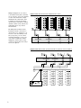
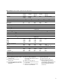
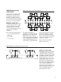
1
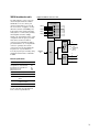
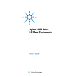
34980A system control modules
34950A 64-channel digital
I/O with memory and counter
This module can be used to simulate
or detect digital patterns. It has eight
8-bit digital I/O channels with handshaking, pattern memory, two 10-MHz
totalizers with gate functions, and a
programmable clock output.
Digital input/output
The digital I/O bits are organized into
two banks of 32-bits. The I/O bits can
be configured and programmed as
inputs or outputs in 8-bit channels.
The digital outputs can be configured
as active drive or tristate outputs
with user supplied pull up resistors
for up to 5 V outputs. The digital
inputs have programmable thresholds
up to 5 V for compatibility with most
digital logic standards.
The onboard pattern memory can
be used to select and output digital
stimulus or bitstream patterns, or to
capture external digital data. Each
bank has independent memory and
directional control so that one bank
can output data while the other
captures data. The memory can
be divided into 16 Kbytes per 8-bit
channel, or you can specify all the
memory onto a single channel on the
bank, resulting in 64 Kbytes on each
bank.
• Internal alarming for maskable
pattern match
Handshake lines
Vin
1.5 – 5 V
(1)
• 1 hardware interrupt per bank
Vout
1.5 – 5 V
(1)
Low Voltage Range
0–5V
Frequency (max)
10 MHz
• Connections via standard 78-pin
Dsub cables or detachable terminal
block
Frequency counter/totalizer
The two channels can be used to
count events, frequency, period, duty
cycle, totalize, and pulse width. The
counter/totalizer also includes
• Programmable gate functionality
• Programmable input thresholds
levels 1.5 V to 5 V
Digital input/output characteristics –
preliminary specs, contact factory
Eight 8-bit channels:
8 bits wide, input or output, non-isolated
• Variable active high drive output
from 1.5 V to 5 V or tristate
10 MHz (max) 50% duty
Vin
1.5 V – 5 V
Totalizer function characteristics
Maximum count
2^32 – 1 (4,294,967,296)
Max input freq
10 MHz (max),
rising or falling edge
programmable
Vin
1.5 V – 5 V
Gate input
1.5 V – 5 V
(1)
Frequency
10 MHz – 10 Hz configurable
divide-by-n 24-bits,
programmable on/off
Vout
1.5 V – 5 V
Accuracy:
100 ppm
Vout
1.5 V – 5V
Iout (max)
30 mA
Frequency (max)
10 MHz [3]
(2)
Figure 10. 34950A 64-channel digital I/O
Interupt
Bit0
8
Bit7
Bit8
8
DIO
bank
1
Bit15
Bit16
Bit23
Bit24
8
Channel
01
32 Bits
Channel
02
Channel
03
32 Bits
Channel
04
Counter/
totalizer
1
IN
Counter/
totalizer
2
IN
Gate
Gate
Channel
09
Channel
10
Bit31
Flag
Ctl
I/O
• 7 configurable handshaking
protocols including synchronous,
asynchronous, and strobe
Interupt
Bit32
8
• Programmable polarity
Bit39
Bit40
8
8
8
DIO
bank
2
Bit47
Bit48
Bit55
Bit56
Bit63
Flag
Ctl
I/O
16
Maximum freq
cycle
System clock generator characteristics
1.5 V – 5 V
• Variable input thresholds from
1.5 V to 5 V
• Source or sink up to 30 mA
Counter function characteristics
(1)
Vin
8
Specifically, the digital I/O channels
also have:
(1) Configurable by 8-bit channel
(2) Current limit per bit
(3) from memory with handshaking
Channel
05
Channel
06
Channel
07
Channel
08
24 Bits
Clock
out
20 MHz – 10 Hz
Channel
11