1
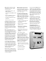
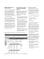
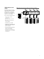
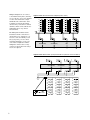
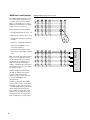
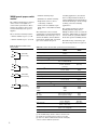
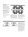
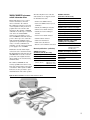
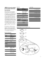
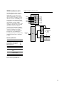
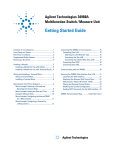
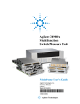
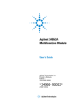
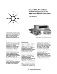
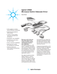
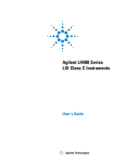
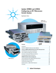
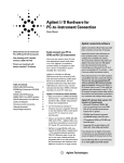
Agilent 34980A
Multifunction Switch/Measure Unit
Data Sheet
C O N F I G U R E , C O N N E C T, G O
• 8-slot mainframe with 19 mix-andmatch plug-in modules so you can
create your own custom configuration
• High-performance switching:
Up to 560 2-wire multiplexer channels or 1024 matrix cross-points in
one mainframe
• Optional built-in 6 1 ⁄ 2 -digit DMM lets
you make 11 measurements with up
to 2000 readings/sec
• Easy to integrate: Built-in Ethernet,
USB 2.0, and GPIB connectivity,
standard connectors and software
drivers for most common programming environments
High-performance unit provides low-cost
alternative to PXI and VXI switch and
measurement platforms
If you use automated test equipment
for design validation or manufacturing, you now have a cost-effective
alternative to PXI and VXI test-system
platforms. The 34980A multifunction
switch/measure unit provides comparable functionality that is much easier
to use than PXI and VXI and costs
less. The 34980A helps you lower your
cost of test and accelerate your testsystem integration and development.
The 34980A handles your system
switching needs up to 20 GHz and
provides basic measurements and
system control. It offers optional DMM
measurements, counter/totalizer
functionality, digital I/O with pattern
capabilities, and analog outputs with
basic waveforms—all in one low-cost,
compact box. And with its standard
connectors and software drivers,
computer-standard I/O, and Web
browser interface, the 34980A easily
integrates into electronic functional
test and data acquisition systems.
Flexible switching, measurements, and system control
The 34980A accommodates up to
8 plug-in modules to give you the
flexibility you need. Choose from 19
different modules to define your own
configuration. You can buy what you
need now and add to it or reconfigure
it as your requirements change.
Whether you are measuring temperature, AC or DC voltage, resistance,
frequency, current, or custom measurements, the 34980A offers the
functionality you need in a single box.
Switch in different measurements with
high-performance signal switching—
no external signal conditioning is
required. Choose between different
switch types and topologies with
frequency ranges from DC to 20 GHz.
The 34980A offers high-density
multiplexers for scanning multiple
channels, matrices for connecting
multiple points at one time, and
general purpose switches for simple
control and high power needs.
Use the 34980A to route individual
signals or monitor multiple signals
over a specified period of time—
monitor a single channel or multiple
channels, set alarms, and identify
irregularities.
The 34980A also offers flexible choices
for system control. You can control
external devices such as microwave
switches, attenuators, solenoids, and
power relays. Or use the digital inputs
to sense limit-switch and digital-bus
status.
2
Optimized for test systems
The 34980A has the performance
you need for medium- to high-density
switching/measurement applications
such as design verification, functional
test and data acquisition. Your signals
are switched to the right measurement
device without compromising signal
integrity. Switch your signals to the
optional internal DMM and achieve
optimal throughput on switch closure
time. Or, if you prefer, you can easily
connect to external instruments such
as DMMs, scopes, power supplies,
and more. What’s more, with the
built-in Ethernet interface, you can
control the 34980A and collect data
from remote locations.
The rugged instrument comes with
a variety of system-ready features:
• Web browser interface shows
settings at a glance and provides
remote access and control
• Self-guiding front panel to configure,
troubleshoot or view data
• Low EMI and efficient system
cooling
• Heavy-duty cabling and connection
options
• Rack mount options
• Relay counters help predict endof-life
• In-rack calibration for reduced
maintenance time
• DMM measurement accuracies
include the switch for simple
calculations
Make system connections easily
and quickly with simple, reliable
connection options:
• Built-in Ethernet, USB 2.0, and
GPIB connectivity
• Standard IVI and LabVIEW software
drivers
• Low-cost, standard 50- or 78-pin
Dsub connectors and cables
• Detachable terminal blocks with
strain relief
Measurements you can trust
Get proven performance from Agilent
instruments, with the resolution,
repeatability, speed, and accuracy
you’ve come to expect.
The 34980A offers built-in signal
conditioning and modular flexibility.
When you use it with the internal
DMM, you can configure each channel
independently for the measurements
you choose. It includes a variety of
features that give you confidence in
your measurements:
• Mass interconnect solutions
In addition, the 34980A comes with
Agilent E2094N IO Libraries Suite
14.0. Quickly establish an error-free
connection between your PC and
instruments—regardless of vendor.
The I/O Libraries provide robust
instrument control and work with the
software development environment
you choose.
Easier signal routing with four
2-wire internal analog buses. You can
route your measurements directly to
the internal DMM, or you can connect
to external instruments through the
analog bus connector on the rear of
the mainframe. And since you have
four 2-wire buses, you can dedicate
one bus for use with the internal
DMM and use the other three buses
for module extensions or additional
signal routing between modules,
reducing your wiring needs.
You can define switch sequences to
control complex signal routing and
the order of switch closures. Assign
a sequence, give it a name and then
execute it with the name you created.
You also can define lists to identify
channels that should never be
connected together.
External trigger capabilities make it
easy for you to time and synchronize
measurements and other events. This
can help you determine when to begin
or end an acquisition.
• 61⁄2 digits of resolution with .004%
of accuracy with DC voltage
measurements
• Alarms per channel—high limit,
low limit, or both
• Math functions—use Mx+B for
custom linear conversions and
converting raw inputs
• Built-in thermocouple reference
for temperature measurements
(34921T)
You can control the DMM directly, or
configure it to work in conjunction
with the switches. Each switch channel
can be configured independently for
measurement functions, scale factors
and alarm limits. Advanced measurement features such as offset compensation, variable integration time, and
delay are also selectable on a perchannel basis.
The DMM inputs are shielded and
optically isolated from the 34980A’s
earth-referenced circuitry and
computer interface, and as a result,
you get up to 300 V of input isolation.
This is important for reducing
ground-loops and common-mode
voltage errors associated with long
wiring runs and floating sources.
Simple DMM calibration is
accomplished with just the analog
bus connection on the rear panel of
the mainframe. You don't need to
remove the mainframe from the rack
or dedicate a channel for calibration.
• Time-stamped readings
The integrated DMM is mounted
inside the mainframe and does not
consume any of the eight useravailable slots. You can access the
DMM through any switch module that
connects to the analog bus, or directly
from the analog bus connector on the
rear of the mainframe. The internal
DMM gives you the flexibility to
measure 11 types of inputs:
• Temperature with thermocouples,
RTDs, or thermistors (with 34921A)
• DC and AC voltage
• 2- and 4-wire resistance
• Frequency and period
• DC and AC current
3
Modules provide flexible system
stimulus and control
System control—with analog outputs,
open-collector digital outputs, clock
generation, and isolated Form-C
relays for controlling external devices.
Additionally, with the microwave
switch/attenuator driver, highfrequency switches and attenuators
can be efficiently controlled external
to the 34980A mainframe.
Analog sources—output either
voltage or current. You can configure
the 4-channel isolated D/A converter
as a point-to-point arbitrary waveform generator that lets you define
up to 500,000 points per waveform.
Digital patterns—send or receive
digital data from your device under
test. With on-board memory you can
output communication protocols and
bit streams or monitor digital input
patterns and interrupt when a userdefined pattern is detected.
Standard interfaces take the
hassle out of connecting to
your PC
Standard Ethernet, USB and GPIB
interfaces are included in every
mainframe. Use one of the interfaces
that is already available in your
computer, or if you prefer, GPIB is
still available.
• USB offers the quickest and easiest
connection scheme—it’s perfect for
small systems and bench connections.
• Ethernet offers high-speed
connections that allow for remote
access and control. Choose a local
area network to filter out unwanted
LAN traffic and speed up the I/O
throughput. Or take advantage of
the remote capabilities and
distribute your tests worldwide.
Monitor, troubleshoot, or debug
your application remotely.
• GPIB has many years of proven
reliability for instrument communication and can be used in existing
GPIB based test systems.
Figure 1 The Web interface makes it easy to set up, troubleshoot and maintain your
system remotely.
Remote access and control
The built-in Web browser interface
provides remote access and control
of the instrument via a Java-enabled
browser such as Internet Explorer.
Using the Web interface, you can set
up, troubleshoot, and maintain your
system remotely.
• View and modify instrument setup
• Open, close, or monitor switches
• Send SCPI commands
• Define and execute switch
sequences
• View error queue
• Get status reports on relay counts,
firmware revisions, and more
Additionally, since the Web interface
is built into the instrument, you can
access it on any operating system that
supports the Web browser without
having to install any special software.
Password protection and LAN lockout are also provided to limit access.
The Web interface makes it easy to
set up, troubleshoot and maintain
your system remotely.
Works with your choice of software
so you can save time and preserve
your software and hardware investments. You can program directly with
SCPI, or use IVI or LabVIEW software
drivers that provide compatibility
with the most popular development
environments and tools:
• Agilent VEE Pro, Agilent T&M
Toolkit (requires Microsoft® Visual
Studio®.NET)
• National Instruments LabVIEW,
LabWindows/CVI, TestStand, and
Switch Executive
• Microsoft Visual Studio.NET, C/C++
and Visual Basic 6
4
Power and flexibility to get your job done
Intuitive front panel with self-guiding menus
6 1⁄2 digit DMM measurements
with 11 functions
Scan multiple channels,
close specified channel list,
or monitor results on a single channel
See results on bright,
multiline display
Use keypad to enter channel number or knob to scroll
Configure measurements by channel
Set up scan lists
Store up to 500,000 readings with timestamp
External trigger to synchronize events
Built-in Ethernet, USB 2.0,
and GPIB interfaces
8-slots connect to optional internal DMM
Access to four
2-wire analog buses
Optional terminal blocks,
standard cables or connector kits
19 plug-in modules to choose from
5
Mix and match 34980A modules to
create your own custom configuration
The 34980A mainframe holds up to eight plug-in modules.
Mix and match them to create a custom system to meet
your switching and system control needs. You can easily
add or replace modules as your needs change.
Table 1. 34980A modules at a glance
Module
Description
Max
volts
Max
current
BW
(MHz)
Scan
ch/sec
Thermal
offset
± 300V
1A
45 MHz
100
< 3 uV
Comments
Multiplexer modules
34921A
40-channel armature multiplexer w/
low thermal offset
Temperature reference
4 current channels
Config as 2- or 4-wire
34922A
70-channel armature multiplexer
± 300V
1A
25 MHz
100
< 3 uV
Config as 2- or 4-wire
34923A
40/80-channel reed multiplexer
± 150V
0.5A
45 MHz
500
< 50 uV
Config as 1-, 2- or 4-wire
34924A
70-channel reed multiplexer
± 150V
0.5A
25 MHz
500
< 50 uV
Config as 2- or 4-wire
34925A
40/80-channel optically isolated
FET multiplexer
± 80V
0.05A
1 MHz
1000
< 3 uV
Config as 1-, 2- or 4-wire
Matrix modules
34931A
Dual 4x8 armature matrix
± 300V
1A
30 MHz
100
< 3 uV
Backplane expandable
34932A
Dual 4x16 armature matrix
± 300V
1A
30 MHz
100
< 3 uV
Backplane expandable
34933A
Dual/Quad 4x8 reed matrix
± 150V
0.5A
30 MHz
500
< 50 uV
Backplane expandable
Config as 1- or 2-wire
General-purpose modules
34937A
28-channel Form C and
4-channel Form A
300V
250AC
1A
5A
10 MHz
N/A
< 3 uV
< 3 uV
34938A
20-channel 5-amp Form A
250AC
5A
1 MHz
N/A
< 3 uV
RF and microwave modules
6
Module
Description
Insertion Isolation
Loss
Freq
Range
VSWR
Input
Impedence
Comments
34941A
Quad 1x4 50 ohm 3 GHz RF multiplexer
0.6dB
3 GHz
< 1.25
50 Ω
@ 1 GHz
34942A
Quad 1x4 75 ohm RF multiplexer
Contact factory
34945A/
34945EXT
Microwave switch/attenuator driver
Can drive up to 64 external switch coils; 32 SPDT switches,8 multiport switches,
8 attenuators, or your own combination. Expand with additional 34945EXTs.
34946A
Dual 1x2 SPDT terminated microwave
switch
< 0.42dB > 85dB
< 0.69dB > 67dB
4 GHz or
20 GHz
< 1.15
< 1.30
50 Ω
@ 4 GHz
@ 20 GHz
34947A
Triple 1x2 SPDT unterminated
microwave switch
< 0.42dB > 85dB
< 0.69dB > 67dB
4 GHz or
20 GHz
< 1.15
< 1.30
50 Ω
@ 4 GHz
@ 20 GHz
> 58dB
75 Ω
System control modules
Description
34950A
64-bit digital I/O with memory
and counter
Eight 8-bit digital I/O channels with programmable polarity, thresholds up to 5 V,
with 7 handshaking protocols and pattern memory. Two 10-MHz frequency counter/
totalizers and programmable clock output to 10MHz.
34951A
4-channel isolated D/A converter
with waveform memory
Output DC voltage up to ± 16 V or DC current up to ± 20 mA.
Output waveforms with a 200 kHz update rate and 16 bits of resolution.
Use on-board memory to create point-to-point waveforms with more than 500,000 points.
34952A
Multifunction module with 32-bit DIO,
2-ch D/A and totalizer
Four 8-bit digital I/O channels, two ± 12-V analog outputs, and a 100-kHz gated totalizer.
34959A
Breadboard module
Create your own custom designs with access to the +12 V and +5 V supplies,
16 GPIO ports and 32 relay drive lines.
34980A multiplexer switch
modules
The 34980A multiplexer modules
can be used to connect one of many
different points to a single point.
You can connect to an external
instrument, or scan multiple analog
signals to the internal DMM.
Choose from the following features:
• 1-wire, 2-wire, or 4-wire
configurations
Figure 2. 34921A 40-channel armature multiplexer with low thermal offset (bank 2)
911
H
ABus1
Current
I
L
L
I
L
042
I
L
043
I
L
044
I
041
• High-density—70 2-wire or 80
1-wire channels
L
H
DMM (MEAS)
L
914
H
ABus2 DMM (SENS)
L
H
ABus3
L
ABus4
Fuse
H
L
H
L
H
L
H
L
Fuse
921
922
923
924
Fuse
Fuse
L
021
026
031
036
022
027
032
037
023
028
033
038
024
029
H
• Bandwidths up to 45 MHz
913
931
H
• High voltage—up to 300 V, 1 A
912
025
034
H
L 030
039
H
L 035
H
L 040
L
• Temperature measurements with
built-in thermocouple reference
junction (34921T)
• AC or DC current measurements
without external shunts
• Connections via standard 50- or
78-pin Dsub cables or detachable
terminal block
7
Multiple multiplexers can connect
to the built-in analog buses, allowing
you to scan up to 560 2-wire channels
or 640 1-wire channels in a single
mainframe. The 34921A also offers
4 channels for directly measuring
current. Or if you need more current
channels, shunts can be added to the
terminal block for easy current
measurements.
Figure 3. 34922A 70-channel armature multiplexer (bank 1 shown)
H
002
009
016
023
030
003
010
017
024
031
004
011
018
025
032
005
012
019
026
033
006
013
020
027
034
007
014
021
028
035
L
The multiplexer modules feature
break-before-make connections to
ensure that no two signals are connected to each other during a scan.
Or, if you prefer, you can control
switching manually to create your
own switch configuration. All the
multiplexer switches have a relay
counter to help predict when relays
need to be replaced.
911
913
912
H
L
H
ABus1 DMM (MEAS)
L
914
H
ABus2 DMM (SENS)
L
H
ABus3
L
ABus4
Figure 4. 34925A 40/80-channel optically isolated FET mux (shown in 1-wire mode bank 2)
911
912
H
L
H
ABus1 DMM (MEAS)
H
L
L
H
914
H
L
922
L
H
ABus4
H
H
L
923
051
061
071
052
062
072
043
053
063
073
044
054
064
074
045
055
065
075
046
056
066
076
047
057
067
077
048
058
068
078
049
059
069
060
H
070
L
924
042
H
L
ABus3
041
050
8
L
ABus2 DMM (SENS)
921
H
913
079
H
080
H
Table 2. Multiplexer selection table—specifications and characteristics*
34921A
34922A
34923A
34924A
34925A
Channels/configurations
40 2-wire
20 4-wire
4-current
70 2-wire
35 4-wire
80 1-wire
40 2-wire
20 4-wire
70 2-wire
35 4-wire
80 1-wire
40 2-wire
20 4-wire
Switch type
Armature
latching
Armature
latching
Reed
Reed
Optically isolated FET
Input characteristics (per channel)
Max volts
± 300 V
Max current (DC, AC RMS)
Switch current
Carry current
1A
2A
Power (W, VA)
[6]
Volt-Hertz limit
[1]
± 300 V
[1]
1A
2A
± 150 V peak
[2]
0.5 A
1.5 A
± 150 V peak
[2]
± 80 V peak
[2]
[8]
0.5 A
1.5 A
0.02 A
60 W
60 W
10 W
10 W
1.6 W
108
108
108
108
107
< 3 uV
< 3 uV
< 50 uV
< 50 uV
< 100 uV 1-wire
< 1.5 Ω
< 1.5 Ω
< 1.5 Ω
N/A
N/A
< 1°C
General specifications
Offset voltage
[3]
Initial closed channel res
Leakage current
[3]
[3]
T/C cold junction accuracy
[3, 10]
[5]
[5]
< 3 uV
< 1.5 Ω
< 700 Ω
N/A
N/A
20nA
N/A
N/A
N/A
N/A
45 MHz
25 MHz
45 MHz
10 MHz 1-wire
25 MHz
1 MHz
-75 dB
-75 dB
-50 dB
-40 dB
-75 dB
-75 dB
-50 dB
-75 dB
-75 dB
-50 dB
-40 dB
-75 dB
-70 dB
-45 dB
N/A
150 pF
150 pF
250 pF
200 pF
130 pF
120 pF
200 pF
170 pF
100pF
300pF (600pF 1-wire)
100 M
10 M
100 k
100 M
10 M
100 k
1000 M
10 M
10 k
1000 M
10 M
10 k
N/A
N/A
N/A
[9]
AC characteristics
Bandwidth at terminal block
[4]
Crosstalk at terminal block (ch-ch)
300 kHz
1 MHz
20 MHz
45 MHz
[4]
Capacitance at terminal block
HI-LO
LO – earth
General characteristics
Relay life, typical
No load
10 V, 100 ma
Rated load
Scanning speeds
[7]
100 ch/sec
100 ch/sec
500 ch/sec
500 ch/sec
1000 ch/sec
Open/ close time, typical
4 ms/4 ms
4 ms/4 ms
0.5 ms/0.5 ms
0.5 ms/0.5 ms
0.25 ms/0.25 ms
Analog bus backplane connection
Yes
Yes
Yes
Yes
Yes
[1] DC or AC RMS voltage, channel-to-channel
or channel-to-earth
[2] Peak voltage, channel-to-channel or
channel-to-earth
[3] Into analog bus. System errors are included
in the internal DMM measurement accuracy
specifications
[4] 50 Ω source, 50 Ω load, differential
measurements verified with 4-port network
analyzer (Sdd21)
[5] With in-rush resistors bypassed
[6] Limited to 6 W of channel resistance power
loss per module
[7] Speeds are for 4-1/2 digits, delay 0, display
off, autozero off, and within bank
[8] DC or peak AC current
[9] Ambient temperature < 30°C
[10] Includes temperature reference and
temperature gradient from reference to
screw terminal block. Measured under worst
case heat loading of the mainframe. For
remote mount of terminal card accuracy
consult factory.
9
34980A matrix switch modules
The 34980A matrix modules are full
cross-point matrices that allow you
to connect any row to any column.
This is a convenient way to connect
multiple test instruments to multiple
points on a device under test.
Choose from the following features:
• Latching armature relays—300 V, 1 A
Figure 5. 34932A dual 4x16 armature matrix
H
L
H
L
H
L
H
L
H
L
L
H
L
H
L
H
L
• High-speed reed relays—150 V, 0.5 A
H
• Configurable dual 4x8 or dual 4x16
modules
L
H
L
• Single-wire configuration (34933A)
• Analog bus expandable rows to
create larger matrices
• Connections via standard 50-pin
Dsub cables or detachable terminal
block
Each cross-point in the matrix switch
has two wires—a high and a low for
the measurement. Or, if you prefer,
the 34933A can be configured as a
single-wire matrix, increasing the
number of channels. The 34933A also
has in-rush resistors on each column
for added protection.
Combine multiple matrix modules
through the 34980A analog buses
to create a larger matrix. Two
matrix rows also can be connected
to the internal DMM for easy
measurements.
Combine your matrix with a multiplexer switch to achieve the desired
switching topology and get a lowercost solution with better specifications.
All the matrix switches include a
relay counter to help predict when
relays need to be replaced. Use the
sequencing feature to easily change
between different cross-point setups.
10
H
L
H
L
H
L
H
L
H
L
H
L
H
L
H
L
H
L
921
ABus1
DMM
(MEAS)
922
ABus2
DMM
(SENS
H
L
H
L
ABus3
923
H
L
H
L
ABus4
924
Table 3. Matrix selection table—specifications and characteristics*
34931A
34932A
34933A
Channels/configurations
dual 4x8
8x8
4x16
dual 4x16
8x16
4x32
dual 4x8
8x8
4x16
quad 4x8, 1-wire
Switch type
Armature
latching
Armature
latching
Reed
non-latching
Input characteristics (per channel)
Max volts
± 300 V
Max current (DC, AC RMS)
Switch current
Carry current
[1]
± 300 V
[1]
± 150 V peak
[2]
1A
2A
1A
2A
60 W
60 W
108
108
108
< 3 uV
< 3 uV
< 50 uV
< 100 uV 1-wire
< 1.5 Ω
< 1.5 Ω
30 MHz
30 MHz
30 MHz
2 MHz 1-wire
-65 dB
-55 dB
-30 dB
-65 dB
-55 dB
-30 dB
-65 dB
-55 dB
-40 dB
50 pF
80 pF
50 pF
80 pF
80 pF
75 pF
Relay life, typical
No load
10 V, 100 ma
Rated load
100 M
10 M
100 k
100 M
10 M
100 k
1000 M
10 M
10 k
Open/close time
4 ms/4 ms
4 ms/4 ms
0.5 ms/0.5 ms
Bank 2
Bank 2
Bank 2
Power (W, VA)
[2]
Volt-Hertz limit
0.5 A
1.5 A
[7]
10 W
General Specifications
Offset voltage
[3]
Initial closed channel res
[3]
< 1.5 Ω
[5]
AC characteristics
Bandwidth at terminal block
[4]
Crosstalk at terminal block (ch-ch)
300 kHz
1 MHz
20 MHz
Capacitance at terminal block
HI-LO
LO – earth
[5]
[4]
General characteristics
Analog bus backplane connection
[1] DC or AC RMS voltage, channel-to-channel or channel-to-earth
[2] Peak voltage, channel-to-channel or channel-to-earth
[3] Into analog bus. System errors are included in the internal DMM
measurement accuracy specifications
[4] 50 Ω source, 50 Ω load, differential measurements verified (Sdd21)
[5] With in-rush resistors bypassed
[6] Limited to 6 W channel resistance power loss per module
[7] Power restrictions allow only 20 channels to be closed at one time
* See User’s Guide for additional specifications
11
34980A general-purpose switch
modules
The 34980A general-purpose switches
can be used to route signals or to
control other system devices. These
switches are ideal for device actuation and switching loads or power
supplies.
Choose from the following features:
• Form C channels up to 1 A, 50 W
• Form A channels up to 5 A, 150 W
Figure 6. 34937A 32-channel Form A/
Form C switch
NC
NO
• Simultaneous channel switching
• Temperature sensor to detect
overheating conditions
• Connections via standard 50-pin
Dsub cables or detachable terminal
block
The 34937A is the most versatile
general-purpose switch with 28 Form C
channels that can switch up to 1 A of
current. In addition, this module has
four Form A channels that can switch
up to 5A of current. For power
COM
Switch type
[1]
Max current (DC, AC RMS)
NC
Channel 028
(1A form C relay)
Power (W, VA)
[2]
COM
Volt-Hertz limit
NO
COM
The built-in relay counter helps predict when relays need to be replaced.
34937A
34938A
28 Form C
4 Form A
20 Form A
Armature, latching
Armature, latching
Form C – 300 V
Form A – 30 VDC/250 VAC
30 VDC/250 VAC
Form C – 1 A (2 A carry)
Form A – 5 A switch
(8 A carry)
5 A switch
(8 A carry)
Input characteristics (per channel)
Max volts (DC, AC RMS)
NO
The 34937A and 34938A contain
latching armature relays where
multiple channels can be closed at the
same time. Additionally, for switching
reactive loads, the optional terminal
blocks have pads for snubbing circuits.
Table 4. GP actuator selection table—specifications and characteristics*
Channels/configurations
Channel 001
(1A form C relay)
switching applications, the 34938A
has 20 5-amp channels in a Form A
topology. Each Form A general-purpose
switch can handle up to 150 W, enough
for many power line-switching
applications.
• Armature latching relays
Channel 029
(5A form A relay)
Form C – 60 W
Form A – 150 W
150 W
108
108
General specifications
Offset voltage
Initial closed channel res
3 uV
3 uV
Form C – 125 mΩ
Form A – 50 mΩ
< 60 mΩ
10 MHz
1 MHz
55 dB
35 dB
15 dB
60 dB
40 dB
Form C 12 pF/ Form A 10 pF
Form C 21 pF/Form A 18 pF
65 pF
105 pF
AC characteristics
NO
COM
Bandwidth at terminal block
Channel 032
(5A form A relay)
[3]
Channel Isolation at terminal block
100 kHz
1 MHz
10 MHz
Capacitance at terminal block
CH – CH
CH – earth
[3]
General characteristics
Relay life no load/rated
Form C – 100 M/100 k
Form A – 50 M/30 k
Open/close time
Form C – 4 ms/4 ms
Form A – 10 ms/10 ms
10 ms/10 ms
Form C – maintain state
Form A – user configurable
user configurable
No
No
Initial/reset relay state
Analog bus backplane connection
[1] DC or AC RMS voltage, channel-to-channel or channel-to-earth
[2] Limited to 6 W of channel resistance power loss per module
[3] 50 Ω source, 50 Ω load, differential measurements verified (S21)
* See User’s Guide for additional specifications
12
50 M/30 k
34980A RF and microwave
switch modules
Figure 7. 34941A Quad 1x4 50 ohm 2 GHz multiplexer
The 34980A offers a variety of RF
and microwave switch modules—
RF multiplexers, SPDT switching
from DC to 20 GHz, or a switch/
attenuator driver module that allows
you to control switches or attenuators
external to the 34980A mainframe.
34941A/42A—from DC to 3 GHz—
The RF switch modules can be used
to switch signals from DC to 3 GHz
and above. This can be useful for
switching signals between oscilloscopes, spectrum analyzers, network
analyzers, and other RF test
equipment.
Choose from the following features:
• 50- or 75- ohm Quad 4-channel
multiplexers
• DC to 3 GHz
• 30 V, 0.5 A, 10 W
11
12
COM
13
14
21
22
COM
23
24
3494xA 31
32
COM
33
34
41
42
COM
43
44
The 34941A and 34942A are
configured as four independent 1x4
RF multiplexers on a single module.
Multiple banks can be connected
together to create a larger multiplexer
—up to 97 RF multiplexer channels in
a single 34980A mainframe. To prevent ground loops, individual multi-
plexers are isolated from each other
and from the mainframe’s chassis.
However, the multiplexer channels
can be chassis grounded with a simple
change. Both 50-ohm and 75-ohm
versions are available.
For typical switch performance
graphs, contact factory.
Figure 8. 34946A dual 1x2 SPDT terminated microwave switch
50
50
101
34946A
COM
102
Dual 1x2 SPOT Terminated Microwave Switch
50
50
201
COM
202
34946A/47A—from DC to 20 GHz—
For applications where you need only
a few high-frequency switches, the
34946A and 34947A offer single-pole,
double-throw switches in either 4-GHz
or 20-GHz options. These modules
internally mount two or three independent Agilent N1810 series coaxial
switches. These switches are well
known for their excellent insertion
loss, isolation and VSWR specifications.
Switch read back capabilities allow
you to query the position of the
switch. You can choose higher density
with the unterminated switches, or
select the terminated switches to
maintain impedance match.
13
Table 5. RF and microwave selection table—specifications and characteristics*
DC to 3 GHz
DC to 20 GHz
[3]
34941A
34942A
34946A
Channels
quad 1x4
quad 1x4
2 SPDT
34947A
3 SPDT
Switch type
50 Ω unterminated,
latching relays
75 Ω unterminated,
latching relays
50 Ω terminated
50 Ω unterminated
DC to 3 GHz
Contact factory
DC to 4 GHz
OR
DC to 20GHz
DC to 4 GHz
OR
DC to 20 GHz
Contact factory
Contact factory
DC to 4 GHz < 0.42dB
@ 20 GHz < 0.69dB
DC to 4 GHz < 0.42 dB
@ 20 GHz < 0.69 dB
Contact factory
Contact factory
DC to 4 GHz < 1.15
@ 20 GHz < 1.30
DC to 4 GHz < 1.15
@ 20 GHz < 1.30
Contact factory
Contact factory
DC to 4 GHz > 85dB
at 20 GHz > 67dB
DC to 4 GHz > 85 dB
at 20 GHz > 67 dB
RF characteristics
Frequency range
[2]
Insertion loss
[2]
(< 40 C/ 80% RH)
VSWR
[3]
Isolation (dB)
[2]
Risetime
< 80 ps
Contact factory
N/A
N/A
Signal delay
< 1 ns
Contact factory
N/A
N/A
Capacitance
30 pF
Contact factory
N/A
N/A
Relay life
300,000 at 30V/10mA load;
100,000 at 10W load RF
Contact factory
> 5 M cycles,
1M w/drive 28-32VDC
> 5 M cycles,
1M w/drive 28-32VDC
[1]
30 V
30 V
7 V DC
7 V DC
Max current
0.5A
0.5A
N/A
Max power (W)
10 W
Switching characteristics
Max volts
[5]
10 W
[5]
1W @ 7 VDC, 50W peak
N/A
[4]
1W @ 7VDC, 50W peak
Offset voltage
10 uV
10 uV
N/A
N/A
Initial channel resistance
1Ω
1Ω
N/A
N/A
Volt-Hertz limit
2 x 10¹⁰
2 x 10¹⁰
Switching time
25 ms
25 ms
< 15 ms
< 15 ms
Connector type
SMA
Mini 75 Ω SMB
SMA
SMA
Analog bus backplane
connection
No
No
No
No
General characteristics
[1] Channel-to-earth
[2] 50 Ω source, 50 Ω load (75 Ω for 34942A)
[3] For more detailed specifications, see the N1810TL
for the 34946A and N1810UL for the 34947A
[4] 10 usec maximum duration
[5] Max power is 1 W between 30 MHz and 1 GHz
for CISPR 11 compliance
* See User’s Guide for additional specifications
14
[4]
34945A/34945EXT microwave
switch/attenuator driver
This module allows you to control
switches attenuators, and other
devices external to the 34980A.
The 34945A provides the power and
control signals for many of the most
popular microwave switches and
attenuators. One 34945A/ 34945EXT
combination can drive up to 64 switch
coils—that’s 32 standard SPDT
switches. You can add up to seven
more 34945EXT boards with external
power to drive up to 512 coils from a
single mainframe. Multiple switch
operations are performed in sequential
order, or for faster, simultaneous
switching, you can connect an external
power supply to the 34945EXT.
Distribution boards enable simple
connections to the external switches.
The distribution boards plug onto the
34945EXT and are used to route the
power and control signals from the
driver module to the switches using
standard cables.
The 34945A/34945EXT also has
sensing capabilities that allows read
back of the actual position of the switch
or attenuator. Drive signals for LED
indicators are also provided to give a
visual indication of the switch position.
The following microwave switches
and attenuators are supported with
the distribution boards:
34945EXT switch drive
(64 channels, TTL drive mode)
• N181x series SPDT switches
Hi output current
2 mA
Lo output voltage
0.4 V
Lo input Current
20 mA
• 876x series SPDT switches (screw
terminals)
Hi output voltage
3V
• 87104x/106x multiport switches
34945EXT position indicator sense inputs
• 87406x series matrix switches
Channels
• 87204x/206x series multiport
switches
Lo input voltage (max)
0.8 V
Hi input voltage (min)
2.5 V
• 87606x series matrix switches
Input resistance
100 k Ω
Maximum input voltage
30 V
• 87222x transfer switches
• 849x series attenuators
• 8490x series attenuators
• Generic screw terminal connections
64
34945EXT switch drive power supply
(34945EXT powered by 34945A)
Voltage
24 V nominal
Current
100 mA continuous +
200 mA (15 msec pulse,
25% duty cycle)
General specifications—preliminary
34945EXT switch drive
(64 channels, low side drive mode)
34945EXT external power connection
Voltage range
4.75 V to 30 V
Driver off voltage (max)
30V
Current limit
2A
Driver off leakage current
< 10 uA
LED indicators
Driver on current
(continuous; 6 chans)
(15 msec, 25% d.c.)
Driver on voltage (max)
300 mA
600 mA Tamb ≤ 40°C
400 mA Tamb > 40°C
1.2 V
Channels
64
Supply voltage
5 V nominal
LED drive current
10 mA nominal
Compliance voltage
0.8 V
Figure 9. 34945A/34945EXT microwave switch/attenuator driver
15
34980A system control modules
34950A 64-channel digital
I/O with memory and counter
This module can be used to simulate
or detect digital patterns. It has eight
8-bit digital I/O channels with handshaking, pattern memory, two 10-MHz
totalizers with gate functions, and a
programmable clock output.
Digital input/output
The digital I/O bits are organized into
two banks of 32-bits. The I/O bits can
be configured and programmed as
inputs or outputs in 8-bit channels.
The digital outputs can be configured
as active drive or tristate outputs
with user supplied pull up resistors
for up to 5 V outputs. The digital
inputs have programmable thresholds
up to 5 V for compatibility with most
digital logic standards.
The onboard pattern memory can
be used to select and output digital
stimulus or bitstream patterns, or to
capture external digital data. Each
bank has independent memory and
directional control so that one bank
can output data while the other
captures data. The memory can
be divided into 16 Kbytes per 8-bit
channel, or you can specify all the
memory onto a single channel on the
bank, resulting in 64 Kbytes on each
bank.
• Internal alarming for maskable
pattern match
Handshake lines
Vin
1.5 – 5 V
(1)
• 1 hardware interrupt per bank
Vout
1.5 – 5 V
(1)
Low Voltage Range
0–5V
Frequency (max)
10 MHz
• Connections via standard 78-pin
Dsub cables or detachable terminal
block
Frequency counter/totalizer
The two channels can be used to
count events, frequency, period, duty
cycle, totalize, and pulse width. The
counter/totalizer also includes
• Programmable gate functionality
• Programmable input thresholds
levels 1.5 V to 5 V
Digital input/output characteristics –
preliminary specs, contact factory
Eight 8-bit channels:
8 bits wide, input or output, non-isolated
• Variable active high drive output
from 1.5 V to 5 V or tristate
10 MHz (max) 50% duty
Vin
1.5 V – 5 V
Totalizer function characteristics
Maximum count
2^32 – 1 (4,294,967,296)
Max input freq
10 MHz (max),
rising or falling edge
programmable
Vin
1.5 V – 5 V
Gate input
1.5 V – 5 V
(1)
Frequency
10 MHz – 10 Hz configurable
divide-by-n 24-bits,
programmable on/off
Vout
1.5 V – 5 V
Accuracy:
100 ppm
Vout
1.5 V – 5V
Iout (max)
30 mA
Frequency (max)
10 MHz [3]
(2)
Figure 10. 34950A 64-channel digital I/O
Interupt
Bit0
8
Bit7
Bit8
8
DIO
bank
1
Bit15
Bit16
Bit23
Bit24
8
Channel
01
32 Bits
Channel
02
Channel
03
32 Bits
Channel
04
Counter/
totalizer
1
IN
Counter/
totalizer
2
IN
Gate
Gate
Channel
09
Channel
10
Bit31
Flag
Ctl
I/O
• 7 configurable handshaking
protocols including synchronous,
asynchronous, and strobe
Interupt
Bit32
8
• Programmable polarity
Bit39
Bit40
8
8
8
DIO
bank
2
Bit47
Bit48
Bit55
Bit56
Bit63
Flag
Ctl
I/O
16
Maximum freq
cycle
System clock generator characteristics
1.5 V – 5 V
• Variable input thresholds from
1.5 V to 5 V
• Source or sink up to 30 mA
Counter function characteristics
(1)
Vin
8
Specifically, the digital I/O channels
also have:
(1) Configurable by 8-bit channel
(2) Current limit per bit
(3) from memory with handshaking
Channel
05
Channel
06
Channel
07
Channel
08
24 Bits
Clock
out
20 MHz – 10 Hz
Channel
11
34951A 4-channel isolated
D/A converter with waveform memory
This module has four independent,
isolated channels that output DC
voltage up to ± 16 V or DC current up
to ± 20 mA. The gain and offset can
be adjusted on-the-fly. Each channel
can be controlled manually, or use
the onboard memory to download a
waveform. These waveforms can be
dynamically allocated among one or
more channels and output as a pointto-point arbitrary waveform generator
at up to 200k points/sec. You can use
the standard sine, square or ramp
wave shapes provided or define your
own wave shape using over 500,000
points and output to a device under
test.
The calibration command connects
the D/A converters to the internal
DMM to be automatically calibrated.
Connections to the module can be
made via standard 50-pin Dsub cables
or a detachable terminal block.
General specifications
Maximum update
rate:
200 kHz point-to-point
Monotonic :
to 16-bits
Isolation:
> 80 VDC/AC peak
(chan-to-chassis or
chan-to-chan)
Synchronization:
Software commands or
external trigger
Internal/external
CLK accuracy:
100 ppm
AC accuracy:
Not specified
DC current
Trigger output
Range:
± 20 mA
Resolution:
16-bit = 630 nA
Accuracy:
± (% value + amps)
(temperature within ± 5°C
of Tcal or *Cal?) 90-day:
± (0.09% + 5.0 uA)
Ripple and noise:
< 2 uArms, 20 Hz to
250 kHz into 250 Ω
Compliance voltage:
± 12 V
Max open circuit
voltage:
< ± 22 V
Level:
TTL compatible
into 1 kΩ (3.3 V logic)
Output impedance:
50 Ω typical
Clock input
Input level:
TTL compatible
(3.3 V logic, 5 V tolerant)
Input impedance:
> 10 kΩ, DC
Maximum rate:
10 MHz
Clock output
Phase-locking I/O trigger characteristics
Level:
TTL compatible
into 1k Ω (3.3 V logic)
Output impedance:
50 Ω typical
Trigger input
Maximum rate:
10 MHz
Input level:
TTL compatible
(3.3 V logic, 5 V tolerant)
Accuracy:
± 100 ppm
Slope:
Rising or falling,
selectable
Pulse width:
> 100 nS
Input impedance:
> 10 kΩ, DC coupled
Figure 11. 34951A 4-channel isolated D/A converter
16 Bits
16 Bits
16 Bits
16 Bits
DAC 1
Channel
01
DAC 2
Channel
02
DAC 3
Channel
03
DAC 4
Channel
04
DC voltage
Amplitude:
± 16 V up to 10 mA
Resolution:
16-bits = 500 uV
Amplitude
accuracy (DC):
User supplied trigger (bidirectional)
Internal clock
Internal trigger
± (0.05% + 3.0 mV
(90 days, Tcal ± 5°C or
*Cal? ± 5°C)
Ripple and noise:
< 2 mVrms, 20 Hz to
250 kHz into 10 kΩ load
Settling time:
40 uS (-full scale to +full
scale step, single channel,
to rated accuracy)
Output impedance:
sensed
User supplied clock (bidirectional)
Disconnect
Immediate
data
16 Bits
Waveform
memory
DACx
HI voltage sense
HI
Customer
system
LO
LO voltage sense
Calibration constant
in non-volatile memory
Calibration bus
(ABUS 1)
< 1 Ω with the load
17
34952A multifunction module
with 32-bit DIO, 2-channel D/A
and totalizer
Digital input/output characteristics
Vin(L)
< 0.8 V (TTL)
The multifunction module offers the
flexibility you need for system control.
The 34952A has four 8-bit digital I/O
channels, a 100-kHz gated totalizer,
and two ± 12 V analog outputs—all on
a single earth-referenced module. The
digital inputs and totalizer input may
be included in a scan list. Alarm limits
for the digital and totalizer inputs are
evaluated continuously, capturing
and logging alarm conditions even
between scans. Connections can be
made via standard 50-pin Dsub cables
or detachable terminal block.
Vin(H)
> 2.0 V (TTL)
Vout(L)
< 0.8 V @ Iout = -400 mA
Vout(H)
> 2.4 V @ Iout = 1 mA
Vout(H) max
< 42 V with external open
drain pull-up
Alarm
Maskable pattern match
or state change
Figure 12. 34952A multifunction module
Four 8-bits channels, 8 bits wide, input or output,
non-isolated
Speed
pling
4 ms (max) alarm sam-
Latency
5 ms (typical) to 34980A
alarm output
Read/write speed
95/s
Totalize input characteristics
Max count
2 26 - 1
Totalize input
100 kHz (max) rising or
falling edge,
programmable
Signal level
1 Vp-p (min) 42 Vpk (max)
Threshold
0 V or TTL
Gate input
TTL-Hi, TTL-Lo, or none
Count reset
Manual or read + reset
Read speed
85 rds/s
Bit7
DAC 1, 2
± 12 V, non-isolated
Resolution
1 mV
IOUT
10 mA max
Settling time
1 ms to 0.01% of output
Accuracy
± (% of output + mV)
1 year
± 5°C 0.25% + 20 mV
Temp. coefficient
18
± (0.015% + 1mV)/°C
Bit0
8
DIO
bank
8
Bit7
Bit0
Bit7
Bit0
8
Bit7
16 Bits
Totalizer
16 Bits
16 Bits
Analog output characteristics
Bit0
8
Cnt H
Cnt L
Gate
Gate
Channel
01
Channel
02
Channel
03
Channel
04
Channel
05
DAC
1
Channel
06
DAC
2
Channel
07
34959A breadboard module
Use this module to create your own
custom designs inside the 34980A
mainframe. You can control your
custom circuits with access to both
the +12 V and +5 V supplies, 32 relay
drive lines and two 8-bit GPIO ports.
Your design can be isolated from the
analog buses or connected by loading
the backplane switches. Simply
mount your custom PC board or other
components into the space provided
and connect via the two ribbon
connectors provided. The module is
provided with two 50- or 78-pin Dsub
connector openings. For custom
connections, use the detachable flat
faceplates for easy modification.
You can program your circuitry using
standard read and write commands
in SCPI.
Backplane
access relays
Bus A
Bus B
Bus C
Bus D
Relay
drivers
50V
Max module power dissipation
6W
Power available
12 V regulation no load to full load
5 V regulation no load to full load
Max power from 12 V
Max power from 5 V
10%
5%
6W
1W
32
+12 V
+5 V
Backplane
IO
CPU
8
General
purpose
in/out
General specifications
Relay drives
Figure 13. 34959A breadboard module
8
3
32, sink up to 100 mA
GPIO ports
Chan 1:
1-8 configure byte as input or
output
Chan 2:
9-16 configure bits individually
as input or outputs
Chan 3:
3 output bits
Available board dimensions:
5.4 x 7.5 x either 0.9 inches height without PC
board, or 0.7 inches high with PC board.
19
34980A system specifications and characteristics
(for complete specifications, see the 34980A Users Guide)
DMM accuracy ± (% of reading + % of range)
Includes measurement error, switching error, and transducer conversion error
Measurement including switch error
[4]
Function
Range
DC voltage
(with 34921A/22A/
31A/32A)
100.0000 mV
1.000000 V
10.00000 V
100.0000 V
300.0000 V
True RMS AC
[5]
voltage
100.0000 mV
to 100.0000 V
90 days
Tcal ± 5°C
1 year
Tcal ± 1°C
Temperature
coefficient
Tcal ± 5°C
0.0030 + 0.0035
0.0020 + 0.0006
0.0015 + 0.0004
0.0020 + 0.0006
0.0020 + 0.0020
0.0040 + 0.0040
0.0030 + 0.0007
0.0020 + 0.0005
0.0035 + 0.0006
0.0035 + 0.0030
0.0050 + 0.0040
0.0040 + 0.0007
0.0035 + 0.0005
0.0045 + 0.0006
0.0045 + 0.0030
0.0005 + 0.0005
0.0005 + 0.0001
0.0005 + 0.0001
0.0005 + 0.0001
0.0005 + 0.0003
3Hz-5Hz
5Hz-10Hz
10Hz-20kHz
20kHz-50kHz
50kHz-100kHz
[6]
100kHz-300kHz
1.00 + 0.03
0.35 + 0.03
0.04 + 0.03
0.10 + 0.05
0.55 + 0.08
4.00 + 0.50
1.00 + 0.04
0.35 + 0.04
0.05 + 0.04
0.11 + 0.05
0.60 + 0.08
4.00 + 0.50
1.00 + 0.04
0.35 + 0.04
0.06 + 0.04
0.12 + 0.05
0.60 + 0.08
4.00 + 0.50
0.100 + 0.004
0.035 + 0.004
0.005 + 0.004
0.011 + 0.005
0.060 + 0.008
0.20 + 0.02
300.0000 V
3Hz-5Hz
5Hz-10Hz
10Hz-20kHz
20kHz-50kHz
50kHz-100kHz
[6]
100kHz-300kHz
1.00 + 0.05
0.35 + 0.05
0.04 + 0.05
0.10 + 0.10
0.55 + 0.20
4.00 + 1.25
1.00 + 0.08
0.35 + 0.08
0.05 + 0.08
0.11 + 0.12
0.60 + 0.20
4.00 + 1.25
1.00 + 0.08
0.35 + 0.08
0.06 + 0.08
0.12 + 0.12
0.60 + 0.20
4.00 + 1.25
0.100 + 0.008
0.035 + 0.008
0.005 + 0.008
0.011 + 0.012
0.060 + 0.020
0.20 + 0.05
Resistance [7]
100.0000 Ω
1.000000 kΩ
10.00000 kΩ
100.0000 kΩ
1.000000 MΩ
10.00000 MΩ
100.0000 MΩ
1mA
1mA
100uA
10uA
5.0uA
500nA
500nA/10MΩ
0.0030 + 0.0035
0.0020 + 0.0006
0.0020 + 0.0005
0.0020 + 0.0005
0.002 + 0.001
0.015 + 0.001
0.300 + 0.010
0.008 + 0.004
0.008 + 0.001
0.008 + 0.001
0.008 + 0.001
0.008 + 0.001
0.020 + 0.001
0.800 + 0.010
0.010 + 0.004
0.010 + 0.001
0.010 + 0.001
0.010 + 0.001
0.010 + 0.001
0.040 + 0.001
0.800 + 0.010
0.0006 + 0.0005
0.0006 + 0.0001
0.0006 + 0.0001
0.0006 + 0.0001
0.0010 + 0.0002
0.0030 + 0.0004
0.1500 + 0.0002
Frequency and
[8]
period
100mV to 300V
3Hz-5Hz
5Hz-10Hz
10Hz-40Hz
40Hz-300kHz
0.10
0.05
0.03
0.006
0.10
0.05
0.03
0.01
0.10
0.05
0.03
0.01
0.005
0.005
0.001
0.001
DC current
(34921 only)
10.00000 mA
100.0000 mA
1.000000 A
< 0.1 V burden
< 0.6V
< 2V
0.005 + 0.010
0.010 + 0.004
0.050 + 0.006
0.030 + 0.020
0.030 + 0.005
0.080 + 0.010
0.050 + 0.020
0.050 + 0.005
0.100 + 0.010
0.002 + 0.0020
0.002 + 0.0005
0.005 + 0.0010
True RMS AC current
(34921A only)
10.00000 mA
[5]
and
1.0 A
3Hz-5Hz
5Hz-10Hz
10Hz-5kHz
1.00 + 0.04
0.30 + 0.04
0.10 + 0.04
1.00 + 0.04
0.30 + 0.04
0.10 + 0.04
1.00 + 0.04
0.30 + 0.04
0.10 + 0.04
0.100 + 0.006
0.035 + 0.006
0.015 + 0.006
3Hz-5Hz
5Hz-10Hz
10Hz-5kHz
1.00 + 0.5
0.30 + 0.5
0.10 + 0.5
1.00 + 0.5
0.30 + 0.5
0.10 + 0.5
1.00 + 0.5
0.30 + 0.5
0.10 + 0.5
0.100 + 0.006
0.035 + 0.006
0.015 + 0.006
[9]
[1] One hour warm-up and a fixed configuration
with slow AC filter, sine wave input, and 6 12⁄
digits. Temperature within ± 5°C of temperature at calibration (Tcal between 18-28°C).
[2] 90 minute warm-up and a fixed configuration
and 6 12⁄ digits. Temperature within ± 1°C of
temperature at calibration (Tcal between
18-28°C).
20
[1]
24 hour
Tcal ± 1°C
100.0000 mA
Frequency, etc.
[2,3]
[3] Relative to calibration standards
[4] 20% over range on all ranges except 300VDC
and AC ranges and 1 ADC and AC current
ranges
[5] For singe wave input > 5% of range. For
inputs from 1% to 5% of range and < 50 kHz
add 0.1% of range additional error.
For AC filter slow.
[6] Typically 30% of reading error at 1 MHz,
limited to 1 x 10⁸ volt-hertz
[7] For 4-wire ohms or 2-wire ohms using scaling
to remove offset. Add 4 ohms additional error
to 2-wire ohms function without scaling.
[8] Input > 100 mV. For 10 mV inputs multiply
% of reading error x 10. For 1 sec aperture.
[9] Specified only for inputs > 10 mA.
For AC filter slow.
Temperature measurement accuracy ± (% of reading + % of range)
Temperature
Type
1-year accuracy
Thermocouple
(34921A only, includes
cold junction accuracy
on terminal block)
B
E
J
K
N
R
S
T
RTD
Thermistor
[1]
[1]
24 hour
Extended range
1-year accuracy
Temp
Coefficient
1100°C to 1820°C
-150°C to 1000°C
-150°C to 1200°C
-100°C to 1200°C
-100°C to 1300°C
300°C to 1760°C
400°C to 1760°C
-100°C to 400°C
1.2°C
1.0°C
1.0°C
1.0°C
1.0°C
1.2°C
1.2°C
1.0°C
400°C to 1100°C
-200°C to -150°C
-210°C to -150°C
-200°C to -100°C
-200°C to -100°C
-50°C to 300°C
-50°C to 400°C
-200°C to -100°C
1.8°C
1.5°C
1.2°C
1.5°C
1.5°C
1.8°C
1.8°C
1.5°C
0.03°C
0.03°C
0.03°C
0.03°C
0.03°C
0.03°C
0.03°C
0.03°C
Ro from 49 Ω to
2.1 K Ω
-200°C to 600°C
0.06°C
0.003°C
2.2k, 5k, 10k
-80°C to 150°C
0.08°C
0.002°C
[1] For total measurement accuracy, add temperature probe error
Typical system speeds—Contact factory
Single channel measurement rates—DMM reading rates
Function
Resolution
rds/s
DCV, 2-wire resistance
4-1/2 digits (0.02 plc)
> 2000
Thermocouple
(0.02 plc) 0.1°C (1 plc)
Contact factory
RTD, thermistor
1°C (0.02 plc)
Contact factory
ACV
6-1/2 digits
250
Frequency, period
4-1/2 digits (10 ms)
Contact factory
21
Measurement characteristics with
optional internal DMM
DC current
Shunt resistance
5 Ω for 10 mA, 100 mA;
0.1 Ω for 1 A
DC voltage
Input protection
1A 250 V fuse on 34921A module
Measurement method
Continuously integrating multi-slope
III A-D converter
A-D linearity
0.0002% of reading + 0.0001% of
range on 10 V range
Input resistance
100 mV, 1 V, 10 V ranges
100 V, 300 V ranges
True RMS AC current
Measurement method
Direct coupled to the fuse and shunt.
AC coupled True RMS measurement
(measures the ac component only)
Selectable 10 M Ω or > 10,000 M Ω
10 M Ω ± 1%
Shunt resistance
5 Ω for 10 mA; 0.1 Ω for 100 mA, 1 A
Input bias current
< 50 pA at 25°C
Input protection
1A 250 V fuse on 34921A module
Input protection
300 V all ranges
Thermocouple
True RMS AC voltage
Conversion
ITS-90 software compensation
Measurement method
Reference junction type
Internal, fixed, or external
Crest factor
Additional crest factor
errors (non-sinewave)
AC coupled True RMS—measures
the AC component of the input with
up to 300 VDC of bias on any range
Maximum of 5:1 at full scale
Crest factor 1-2 0.05% of reading
Crest factor 2-3 0.15% of reading
Crest factor 3-4 0.30% of reading
Crest factor 4-5 0.40% of reading
Input impedance
1 M Ω ± 2% in parallel with 150 pF
Input protection
300 Vrms all ranges
Resistance
Measurement method
Selectable 4-wire or 2-wire ohms
Current source
referenced to LO input
Offset compensation
Selectable on 100 Ω, 1k Ω,
10k Ω ranges
Maximum lead resistance
10% of range per lead for 100 Ω
and 1k Ω ranges. 1k Ω on all
other ranges
Input protection
300 V on all ranges
Frequency and period
22
Measurement method
Reciprocal counting technique
Voltage ranges
Same as AC voltage function
Gate time
1s, 100 ms, or 10 ms
Measurement timeout
Selectable 3 Hz, 20 Hz, 200 Hz LF limit
Open thermocouple check
Selectable per channel. Open > 5k Ω
Thermistor
44004, 44007, 44006 series
RTD
a = 0.00385 (DIN) and a = 0.00392
Measurement noise rejection 60 (50) Hz
[1]
DC CMRR
AC CMRR
140 dB
70 dB
Integration time
Normal mode rejection
200 plc/3.33 s (4 s)
100 plc/1.67 s (2 s)
20 plc/333 ms (400 ms)
10 plc/167 ms (200 ms)
2 plc/33.3 ms (40 ms)
1 plc/16.7 ms (20 ms)
< 1 plc
DC CMRR 140 dB
AC CMRR 70 dB
[1]
[2]
[3]
[4]
[5]
[6]
[7]
[8]
[9]
[10]
[2]
[3]
105 dB
[3]
100 dB
[3]
95 dB
[3]
90 dB
85 dB
60 dB
0 dB
For 1 K Ω unbalance in LO lead
For power line frequency ± 0.08%
For power line frequency ± 1% use 75 dB or ± 2.5% use 60 dB
Reading speeds for 60 Hz and (50 Hz) operation
For fixed function and range, readings to memory, scaling and alarms
off, autozero off
Maximum limit with default settling delays defeated
Speeds are for 4 12⁄ digits, delay Ø, display off, autozero off
Isolation voltage (ch - ch, ch - earth) 300 VDC, AC rms
6 12⁄ digits = 22 bits, 5 12⁄ digits = 18 bits, 4 12⁄ digits = 15 bits
Assumes relative time format (time since start of scan)
System specifications
Scanning inputs
Analog:
34921A, 34922A, 34923A, 34924A, and
34925A multiplexer channels
General specifications
Power supply
Universal 100 V to 240 V ± 10%
Power line frequency
50 – 60 Hz ± 10% automatically sensed
Power consumption
150 VA
Operating environment
Full accuracy for 0°C to 55°C
Full accuracy to 80% R.H. at 40°C
IEC 60664-1 pollution degree 1
Storage environment
-40°C to 70°C
Interval, external, button press, software,
or on monitor channel alarm
Mainframe dimensions
133H x 426W x 341D mm (5.25” x 16.8” x 14”)
Full rack, 3 units high
Scan count
1 to 50,000 or continuous
Mainframe weight:
8.8 kg (19.6 lbs)
Scan interval
0 to 99 hours; 1ms step size
Module dimensions
280 x 170 x 27 mm (11” x 6.7” x 1”)
Channel delay
0 to 60 seconds per channel; 1 ms step size
Safety conforms to
CSA, UL/IEC/EN 61010-1
External trig delay
< 2 ms. With monitor on < 200 ms
EMC conforms to
IEC/EN 61326-1, CISPR 11
External trig jitter
< 2 ms
Warranty
1 year
Digital:
34950A/52A digital in and totalize
Scan triggering
Source
Alarms
[1]
Software
Analog inputs
Hi, Lo, or Hi + Lo evaluated each scan
Digital inputs
34950A/52A digital in maskable pattern
match or state change
Agilent connectivity software included
34950A/52A frequency and totalize:
Hi limit only
Minimum system requirements (IO libraries and drivers)
Agilent IO Libraries Suite 14.0 (E2094N)
PC hardware
Intel Pentium 100 MHz, 64 Mbyte RAM,
210 Mbyte disk space
Display 800 x 600, 256 colors, CD-Rom drive
Monitor channel
Alarm evaluated each reading
Alarm outputs
4 TTL compatible
Selectable TTL logic Hi or Lo on fail
Operating system
5 ms (typical)
Computer interfaces
Latency
Memory
[2]
Windows® 98 SE/NT/2000/XP
Standard LAN 10BaseT/100BaseTx
Standard USB 2.0
IEEE 488.2 GPIB
Software driver support for programming languages
Type
Volatile
Readings
500,000 with timestamp, readable during scan
States
5 instrument states with user label
Alarm queue
Up to 20 events with channel number, reading,
and timestamp
System features
Per-channel math
Min/max/average
Individual Mx+B scaling and calculated real
time
Power fail recovery
Save switch states
Relay maintenance
Counts each relay closure and stores on
module User resettable
Real-time clock
Battery-backed, 20-year typical life
Software drivers:
IVI-C and IVI COM for
Windows NT/2000/XP
Compatible with programming tools and environments:
Agilent VEE Pro, Agilent T&M Toolkit
(requires Visual Studio.NET)
National Instruments Test Stand,
Measurement Studio, LabWindows/CVI,
LabVIEW, Switch Executive
Microsoft Visual Studio.NET, C/C++,
Visual Basic 6
[1] Storage at temperatures above 40°C will decrease battery life
[2] Load IO Libraries Version M for Windows NT support
23
Ordering information
Description
Optional
terminal block
Interconnect
cables /
connector kits
N/A
N/A
34921T
Qty 2 per module
Y1135A – 1.5m
Y1136A – 3m
Y1139A
Comments
Mainframe
34980A
Multifunction switch/measure mainframe—
holds up to 8 plug-in modules
Only available with option
“DMM” at this time
Multiplexer modules
34921A
40-channel armature multiplexer w/low thermal offset
34923A
40/80-channel reed multiplexer
34923T (1 or 2 wire)
34925A
40/80-channel optically isolated FET multiplexer
34925T (1 or 2 wire)
34922A
70-channel armature multiplexer
34922T
34924A
70-channel reed multiplexer
34924T
Order 34921T for temp reference
Qty 2 per module
Y1137A – 1.5m
Y1138A – 3m
Y1140A
Matrix modules
34931A
Dual 4x8 armature matrix
34931T
34932A
Dual 4x16 armature matrix
34932T
34933A
Dual/quad 4x8 reed matrix
34933T (1 or 2 wire)
Qty 2 per module
Y1135A – 1.5m
Y1136A – 3m
Y1139A
GP/actuator modules
34937A
32-channel Form C/Form A general-purpose switch
34937T
34938A
20-channel 5-amp Form A switch
34938T
Qty 2 per module
Y1135A – 1.5m
Y1136A – 3m
Y1139A
RF and microwave modules
34941A
Quad 1x4 50-ohm 2-GHz RF multiplexer
N/A
N/A
Requires standard SMA cables
and adapters
34942A
Quad 1x4 75-ohm RF multiplexer
N/A
N/A
Requires mini 75 ohm cables and
adapters
34945A
Microwave switch/attenuator driver
N/A
N/A
Requires 34945EXT and optional
distribution boards
34946A
004
020
Dual 1x2 SPDT terminated microwave switch
4 GHZ switches installed
20 GHz switches installed
N/A
N/A
Requires standard SMA cables
and adapters
34947A
004
020
Triple 1x2 SPDT unterminated microwave switch
4 GHZ switches installed
20 GHz switches installed
N/A
N/A
Requires standard SMA cables
and adapters
System measurement and control modules
24
34950A
64-bit digital I/O with memory and counter
34950T
Qty 2 per module
Y1137A – 1.5m
Y1138A – 3m
Y1142A
34951A
4-channel isolated D/A converter with waveform Memory
34951T
34952A
Multifunction module with 32-bit DIO, 2-ch D/A and Totalizer
34952T
Qty 1 per module
Y1135A –1.5m
Y1136A – 3m
Y1141A
34959A
Breadboard module
N/A
“DMM” option required for
calibration
Single 50 pin Dsub connector
Single 50 pin Dsub connector
Any terminal block can be used
assuming 50 or 78 pin Dsub is used
Accessories
Y1130A
Rackmount kit for 34980A, forward or reverse mount
Cables/connector Kits
Y1135A
1.5m 50pin Dsub, M/F twisted pair with outer shield cable – 300 V
Y1136A
3m 50pin Dsub, M/F twisted pair with outer shield cable – 300 V
Y1137A
1.5m 78pin Dsub, M/F twisted pair with outer shield cable – 300V
Y1138A
3m 78pin Dsub, M/F twisted pair with outer shield cable – 300 V
Y1139A
Solder cup connector kit for 34921/23/25/31/32/33/37/38 –50 pin Dsub
female – 125 V
Y1140A
Solder cup connector kit for 34922, 34924 – 78 pin Dsub female – 60 V
Y1141A
Solder cup connector kit for 34951, 34952 – 50 pin Dsub male – 125V
Y1142A
Solder cup connector kit for the 34950A – 78 pin Dsub male – 60 V
34945A accessories
34945EXT
External driver for 34945A, one required for each 64 coils
Y1150A
34945A distribution board for 8 N181x SPDT switches
Y1151A
34945A distribution board for two 87104x/106x multiport or 87406B matrix
switches
Y1152A
34945A distribution board for one 87204x/206x or 87606B switch and
two N181x switches
Y1153A
34945A distribution board for two 84904/5/8x or 8494/5/6 step attenuators
Y1154A
34945A distribution board for two 87222 transfer switches and six N181x SPDT
switches
Y1155A
34945A distribution board w/ generic screw terminals for driving 16 switch coils
Thermocouples/thermistors
34307A
10 pack of J type thermocouples
34308A
5 pack of 10k thermistors
For additional information please visit: http://www.agilent.com/find/34980a
Related Agilent literature
Publication title
Publication type
Agilent VEE Pro 7.0
Data sheet
Publication number
5988-6302EN
Agilent W1140A-TK2
T&M Toolkit 2.0 with Test Automation
Data sheet
5989-1441EN
Agilent E2094N IO Libraries Suite 14.0
Data sheet
5989-1439EN
25
Agilent Technologies’ Test and Measurement
Support, Services, and Assistance
Agilent Technologies aims to maximize the value
you receive, while minimizing your risk and problems. We strive to ensure that you get the test and
measurement capabilities you paid for and obtain
the support you need. Our extensive support
resources and services can help you choose the
right Agilent products for your applications and
apply them successfully. Every instrument and
system we sell has a global warranty. Support is
available for at least five years beyond the production
life of the product. Two concepts underlie Agilent’s
overall support policy: “Our Promise” and “Your
Advantage.”
Our Promise
Our Promise means your Agilent test and measurement equipment will meet its advertised
performance and functionality. When you are
choosing new equipment, we will help you with
product information, including realistic performance specifications and practical recommendations from experienced test engineers. When you
receive your new Agilent equipment, we can help
verify that it works properly and help with initial
product operation.
Your Advantage
Your Advantage means that Agilent offers
a wide range of additional expert test and
measurement services, which you can purchase
according to your unique technical and business
needs. Solve problems efficiently and gain a
competitive edge by contracting with us for
calibration, extra-cost upgrades, out-of-warranty
repairs, and onsite education and training, as well
as design, system integration, project management,
and other professional engineering services.
Experienced Agilent engineers and technicians
worldwide can help you maximize your productivity,
optimize the return on investment of your Agilent
instruments and systems, and obtain dependable
measurement accuracy for the life of those products.
Agilent Email Updates
www.agilent.com/find/emailupdates
Get the latest information on the products and
applications you select.
Agilent T&M Software and Connectivity
Agilent’s Test and Measurement software and
connectivity products, solutions and developer
network allows you to take time out of connecting
your instruments to your computer with tools
based on PC standards, so you can focus on your
tasks, not on your connections. Visit
www.agilent.com/find/connectivity
for more information.
For more information on Agilent
Technologies’ products, applications or
services, please contact your local Agilent
office. The complete list is available at:
www.agilent.com/find/contactus
Phone or Fax
United States:
(tel) 800 829 4444
(fax) 800 829 4433
Canada:
(tel) 877 894 4414
(fax) 800 746-4866
China:
(tel) 800 810 0189
(fax) 800 820 2816
Europe:
(tel) 31 20 547 2111
Japan:
(tel) (81) 426 56 7832
(fax) (81) 426 56 7840
Korea:
(tel) (080) 769 0800
(fax) (080)769 0900
Latin America:
(tel) (305) 269 7500
Taiwan:
(tel) 0800 047 866
(fax) 0800 286 331
Other Asia Pacific Countries:
(tel) (65) 6375 8100
(fax) (65) 6755 0042
Email: [email protected]
Product specifications and descriptions in
this document subject to change without
notice.
Microsoft, Windows and Visual Studio are
U.S. registered trademarks of Microsoft
Corporation.
© 2004 National Instruments Corporation
© Agilent Technologies, Inc. 2004
Printed in USA, October 20, 2004
5989-1437EN