1
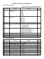
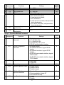
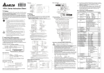
Group 3: Output Function Parameters
Parameters
3-00
3-01
3-02
3-03
Functions
Settings
Desired freq. attained 1.0 ~ 400 Hz
Terminal count value 0 ~ 999
Preliminary count value 0 ~ 999
Multi-function (relay
0: not used
output)
1: AC drive operational
2: Max. Output Freq. Attained
3: Zero Speed
4: Over Torque
5: Base-Block (B.B.)
6: Low Voltage Detection
7: AC Drive Operation Mode
8: Fault Indication
9: Desired Freq. Attained
10: PLC Program Running
11: PLC Program Step Complete
12: PLC Program Complete
13: PLC Program Operation Pause
14: Terminal Count Value Attained
15: Preliminary Count Value Attained
16: Ready State Indicator
Factory
Setting
1.0
0
0
8
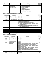
Group 4: Input Function Parameters
Parameters
a
4-00
a
4-01
a
4-02
4-03
4-04
4-05
4-06
Functions
Potentiometer bias freq.
Potentiometer bias
polarity
Potentiometer freq. gain
Potentiometer
reverse motion
enable
Multi-function input
terminal1 (M1)
(d 0〜d 20)
Multi-function input
terminal 2(M2)
Multi-function input
terminal 3(M3)
(d 0, d 4〜d 20)
Settings
0.0〜350Hz
0: positive bias
1: negative bias
1〜200%
0: not used
1: reverse motion enable
2: forward motion only
0: not used
1: M0: FWD/STOP, M1: REV/STOP
2: M0: RUN/STOP, M1: FWD/REV
3: M0, M1, M2: 3-wire operation control mode
4: External fault, normally open (N.O.)
5: External fault, normally closed (N.C.)
6: RESET
7: multi-step speed command 1
8: multi-step speed command 2
9: jog operation
10: accel/decel speed inhibit
11: first or second accel/decel time selection
12: base-block (B.B.),normally open (N.O.)
13: base-block (B.B.),normally closed (N.C)
9
Factory
setting
0.0
0
100
0
1
6
7