1
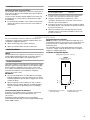
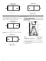
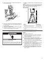
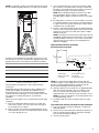
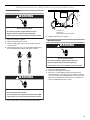
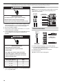
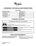
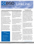
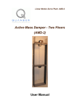
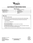
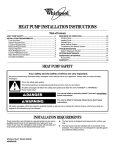
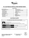
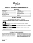
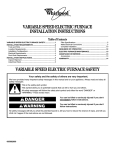
AIR HANDLER INSTALLATION INSTRUCTIONS
Table of Contents
AIR HANDLER SAFETY .................................................................1
INSTALLATION REQUIREMENTS ................................................2
Tools and Parts ............................................................................2
System Requirements..................................................................2
Location Requirements ................................................................2
Installation Configurations ...........................................................3
Drain Pan Connections ................................................................4
Electrical Requirements—
Models Without Factory-Installed Electric Heat ..........................5
Electrical Requirements—
Models With Factory-Installed Electric Heat ...............................6
Ductwork Requirements ..............................................................6
INSTALLATION INSTRUCTIONS ..................................................6
Inspect Shipment .........................................................................6
Install Condensate Drain..............................................................7
Install Ductwork............................................................................8
Verify Orifice Size .........................................................................8
Connect Refrigerant Lines ...........................................................8
Make Electrical Connections—
Models Without Factory-Installed Electric Heat ..........................9
Make Electrical Connections—
Models with Factory-Installed Electric Heat ..............................10
Complete Installation..................................................................14
SEQUENCE OF OPERATION ......................................................21
Cooling (Cooling Only or Heat Pump)........................................21
Heating (Electric Heat Only) .......................................................21
Heating (Heat Pump) ..................................................................21
Variable Speed Features ............................................................21
AIR HANDLER MAINTENANCE ..................................................22
ASSISTANCE OR SERVICE .........................................................22
Accessories ................................................................................22
WARRANTY ..................................................................................23
AIR HANDLER SAFETY
Your safety and the safety of others are very important.
We have provided many important safety messages in this manual and on your appliance. Always read and obey all safety
messages.
This is the safety alert symbol.
This symbol alerts you to potential hazards that can kill or hurt you and others.
All safety messages will follow the safety alert symbol and either the word “DANGER” or “WARNING.”
These words mean:
DANGER
WARNING
You can be killed or seriously injured if you don't immediately
follow instructions.
You can be killed or seriously injured if you don't follow
instructions.
All safety messages will tell you what the potential hazard is, tell you how to reduce the chance of injury, and tell you what can
happen if the instructions are not followed.
Whirlpool® Models WAHMS, WAHMV
065937402
INSTALLATION REQUIREMENTS
These instructions are intended as a general guide only for use by
qualified persons and do not supersede any national or local
codes in any way. Compliance with all local, state, or national
codes pertaining to this type of equipment should be determined
prior to installation.
Read this entire instruction manual, as well as the instructions
supplied in separate equipment, before starting the installation.
All models are designed for indoor installation only.
The installation of the air handler, field wiring, warm air ducts, etc.
must conform to the requirements of the National Electrical
Code, ANSI/NFPA No. 70 (latest edition) in the United States, and
any state laws, and local ordinances (including plumbing or
wastewater codes). Local authorities having jurisdiction should
be consulted before installation is made. Such applicable
regulations or requirements take precedence over the general
instructions in this manual.
Install the conditioned air plenum, ducts and air filters (not
provided) in accordance with NFPA 90B Standard for the
Installation of Warm Air Heating and Air-Conditioning Systems
(latest edition).
The air handler is provided with flanges for the connection of the
plenum and ducts.
Air filters (not provided) must be listed as Class 2 furnace air
filters.
The air handler can be used with R-22 or R410A from the factory.
The air handler is shipped from the factory completely
assembled. Some models are configured for upflow air discharge
only, and some models are configured for upflow or horizontal
left-hand air discharge. The air handler cabinet conforms to
2 percent or less air leakage.
Do not remove the cabinet knockouts until it has been
determined which knockouts will need to be removed for the
installation.
Select the final installation position which best suits the site
conditions. Consider required clearances, space, routing
requirements for refrigerant line, condensate disposal, filters,
ductwork, wiring, and accessibility for service. Refer to the air
handler rating plate on the air handler for specific information.
Tools and Parts
Gather the required tools and parts before starting installation.
Read and follow the instructions provided with any tools listed
here.
Tools Needed
¹⁄₄" nut driver
■
■
Level
■
Hammer
■
Screwdriver
■
Sealant
■
Adjustable wrench
■
Parts Needed
Check local codes, check existing electrical supply, and read
“Ductwork Requirements,” and “Electrical Requirements,” before
purchasing parts.
Tape measure
■
UL listed wire nuts
■
Replacement orifice (if needed). See “Verify Orifice Size.”
The correct orifice size may be contained in the
replacement orifice package located inside the control box
of the outdoor unit. If this package does not contain the
correct orifice for your air handler, you must purchase the
correct orifice size.
System Requirements
The air handler is designed to match, and must be used with
outdoor units as rated. The indoor units are manufactured with an
interchangeable refrigerant metering orifice to provide optimum
refrigerant control and system performance with a variety of
different capacities of outdoor units.
In some cases, the rating of the outdoor unit may require that the
air handler coil assembly orifice be changed to obtain rated
performance.
Location Requirements
WARNING
NOTE: When used on cooling applications, excessive sweating
may occur when the air handler is installed in a very humid
space.
■ If installed in an unconditioned space, sealant should be
applied around the electrical wires, refrigerant tubing, and
condensate lines where they enter the cabinet.
■
Electrical wires should be sealed on the inside where they exit
the conduit opening. Sealant is required to prevent air
leakage into and condensate from forming inside the air
handler, control box, and on electrical controls.
■
The air handler must be installed in such a way as to allow
free access to the coil/filter compartment and blower/control
compartment.
■
The air handler must be installed in a level position to ensure
proper condensate drainage.
Explosion Hazard
Keep flammable materials and vapors, such as
gasoline, away from air handler.
Place air handler so that heating elements are at least
18 inches (46 cm) above the floor for a garage
installation.
Failure to follow these instructions can result in death,
explosion, or fire.
2
18" and 24" models
320 sq. in.
Non-Ducted Return Closet Installation
30" and 36" models
360 sq. in.
The air handler can be installed in a closet with a false bottom to
form a return air plenum or be installed with a return air plenum
under the air handler.
Louvers or return air grilles are field supplied. Local codes may
limit application of systems without a ducted return to singlestory buildings.
■ For an air handler installed in a closet with a louvered return
opening, the minimum open area for the louvers will be as
shown below.
42", 48" and 60" models
450 sq. in.
Installation Clearances
■
If the free area is not known, assume a 25% free area for
wood or a 75% free area for metal louvers or grilles.
■
Using the louver dimensions and the 25% or 75%
assumption, determine if the louver open area meets the
minimum open area listed above.
■
If the return air plenum is used, the return air grille should be
immediately in front of the opening in the plenum to allow for
the free flow of return air.
■
When not installed in front of the opening, there must be
adequate clearance around the air handler to allow for the
free flow of return air.
Installation Configurations
For ease in installation, it is best to make any necessary coil
configuration changes before setting air handler in place. See
“Installation Configuration Options.”
■ Upflow air discharge only contains 1 drain pan.
■
Upflow or horizontal airflow contains 2 drain pans.
Vertical Installations
Upflow
The air handler must be supported on the bottom only and set on
a field-supplied supporting frame with an air return opening.
Securely attach the air handler to the supporting frame.
Suspended Cabinet Installation
NOTE: Air handlers cannot be installed horizontally lying on or
suspended from either the front or back of the air handler. It must
be positioned with one side parallel to the floor when in the
horizontal position.
The suspending means must be field fabricated, and should
consist of 2 “cradles” made by attaching 2 rods to a length of
angle iron or suitable gauge steel.
Installation Configuration Options
Shading indicates proper line connections
Upflow
As shipped from the factory
(return in bottom)
Horizontal Installations
Horizontal installations can be left-hand or right-hand air supply.
Adequate support must be provided to ensure cabinet integrity.
Ensure that there is adequate room to remove, service and
access panels if installing in the horizontal position. For correct
horizontal coil installation, see “Installation Configuration
Options” later in this section.
IMPORTANT:
■ This coil is provided with a secondary drain that should be
trapped and piped to a location that will give the occupant a
visual warning that the primary drain is clogged. See “Install
Condensate Drain.”
■
When an evaporator coil is installed in an attic or above a
finished ceiling, an auxiliary drain pan should be provided
under the air handler as specified by most local building
codes.
Conversion from Vertical to Horizontal
An upflow only air handler may be converted to horizontal air
discharge by installing a horizontal drain pan kit. See
“Accessories.”
An upflow/horizontal air handler may be converted from
horizontal left-hand discharge to horizontal right-hand discharge
without additional parts.
A
A
B
C
B
A. Horizontal drain connections
(left or right hand)
B. Upflow drain connections
C. Bottom/filter frame
3
.
Horizontal Right
Horizontal Left
Left to Right Airflow: Requires drain pan
location change.
Factory ready (on some models)
Drains
Drains
A
C
B
A
A. Drain connections
B. Coil access cover
C. Blower access cover
A. Drain connections
Drain Pan Connections
Horizontal Installations can be either “Right” or “Left.”
For Horizontal Right Installations, a drain pan location change is
required. Use drain connections marked “A” below.
Conversion to Horizontal Right
Before Conversion
Horizontal Right
Left to Right Airflow: Requires drain pan
location change.
A
Drains
B
G
A
C
A. Drain connections
For Horizontal Left Installations, use drain connections marked
“A” below.
F
E
Horizontal Left
D
Factory ready (on some models)
A. Blower
B. Top cap
C. Coil/drain pan assembly (consists of coil,
bottom drain pan and side drain pan)
Drains
C
B
A. Drain connections
B. Coil access cover
C. Blower access cover
4
A
D. Coil support bracket
E. Filter access door
F. Bottom drain pan
G. Side drain pan
1. Remove screws from the blower access cover and lift off of
the air handler. Set aside.
2. Remove screws from the coil access cover and lift off of the
air handler. Set aside.
3. Remove screws from the coil support bracket and lift off of
the air handler. Set aside.
7. Install the coil support bracket on the opposite side of the air
handler.
NOTE: For models 2.5 tons to 5 tons, the bracket attached to the
top cap will need to be switched to the opposite side of the coil.
This is to prevent blowoff in the horizontal position when the
airflow is changed from left-hand to right-hand.
After Conversion
A
B
C
A
D
E
G
A. Coil support bracket screws
4. Remove the coil/drain pan assembly by lifting and sliding out.
The assembly consists of the coil, the bottom drain pan and
the side drain pan.
5. Remove the side drain pan from the coil/drain pan assembly
and install on the opposite side.
6. Reinstall the coil/drain pan assembly in the same orientation
as before by lifting and sliding into the air handler.
F
A. Blower
B. Top cap
C. Coil/drain pan assembly (consists of coil,
bottom drain pan and side drain pan)
D. Side drain pan
E. Bottom drain pan
F. Filter access door
G. Coil support bracket
8. Determine knockouts required for drain line connections and
remove.
9. Replace the blower and coil access covers.
Electrical Requirements—Models Without Factory-Installed Electric Heat
WARNING
NOTES:
■ Use copper conductors only.
■
All field wiring must be done in accordance with National
Electrical Code, applicable requirements of UL and local
codes where applicable.
■
Electrical wiring, disconnect means and overcurrent
protection are to be supplied by the installer. Refer to the air
handler rating plate for maximum overcurrent protection,
minimum circuit ampacity, as well as operating voltage.
■
The power supply must be sized and protected according to
the specifications supplied on the product.
■
This air handler is factory-configured for 120-volt or 240-volt,
single phase, 60 cycles. For 208-volt applications, see
“208-Volt Conversion” in the “Make Electrical Connections—
Models Without Factory-Installed Electric Heat” section.
■
For optional electric heater applications, see “Accessories.”
Refer to the instructions provided with the accessory for
proper installation.
Electrical Shock Hazard
Electrically ground air handler.
Connect ground wire to ground terminal marked “GND”.
Failure to do so can result in death or electrical shock.
5
Electrical Requirements—Models With Factory-Installed Electric Heat
NOTES:
■ Use copper conductors only.
WARNING
Electrical Shock Hazard
■
All field wiring must be done in accordance with National
Electrical Code, applicable requirements of UL and local
codes where applicable.
■
Electrical wiring, disconnect means and overcurrent
protection are to be supplied by the installer. Refer to the air
handler rating plate for maximum overcurrent protection,
minimum circuit ampacity, as well as operating voltage.
■
The power supply must be sized and protected according to
the specifications supplied on the product.
■
This air handler is factory-configured for 240-volt, single
phase, 60 cycles. For 208-volt applications, see “208-Volt
Conversion” in the “Make Electrical Connections—Models
Without Factory-Installed Electric Heat” section.
Electrically ground electric heater.
Connect ground wire to ground terminal
marked “GND.”
Use copper wire rated for supply connection.
Correct wire gauge is shown in the chart below.
Failure to follow these instructions can result in
death or electrical shock.
Rating Plate Ampacity
AWG
21 - 30
10
31 - 40
8
41 - 60
6
Ductwork Requirements
■
Install the conditioned air plenum, ducts and air filters (not
provided) in accordance with NFPA 90B Standard for the
Installation of Warm Air Heating and Air-Conditioning
Systems (latest edition).
■
The air handler is provided with flanges for the connection of
the plenum and ducts.
■
The air handler is equipped with flanges that can form a filter
rack for the installation of the air filter, or the filter may be
installed as part of the return air duct system.
■
Air filters must be listed as Class 2 furnace air filters.
■
Supply and return ductwork must be adequately sized to
meet the system’s air requirements and static pressure
capabilities. Ductwork should be insulated with a minimum of
1" thick insulation with a vapor barrier in conditioned areas or
2" minimum in unconditioned areas.
■
Supply plenum should be the same size as the flanged
opening provided around the blower outlet and should
extend ideally at least 3 ft from the air handler before turning
or branching off plenum into duct runs. The plenum forms an
extension of the blower housing and minimizes air expansion
losses from the blower.
INSTALLATION INSTRUCTIONS
Inspect Shipment
WARNING
Excessive Weight Hazard
Use two or more people to move and install air handler.
Failure to do so can result in back or other injury.
These air handlers are completely factory assembled, and all
components are performance tested. Each air handler consists of
a blower assembly, refrigerant coil, and controls, in an insulated
galvanized steel factory finished enclosure. Knockouts are
provided for electrical wiring entrance.
6
1. Check the air handler rating plate to confirm specifications
are as ordered.
2. Upon receipt of air handler, thoroughly inspect it for possible
shipping damage. Closely examine the air handler inside the
carton if the carton is damaged.
If damage is found, it should be noted on the carrier’s freight bill.
Damage claims should be filed with the carrier immediately.
Claims of shortages should be filed with the seller within 5 days.
NOTE: If any damages are discovered and reported to the carrier,
do not install the air handler because your claim may be denied.
3. Connect primary drain line connection to the primary drain
pan connection. The primary drain connection is flush with
the bottom of the inside of the pan. Secondary connection is
raised above the bottom of the inside of the pan.
NOTE: When making drain fitting connections to the drain
pan, hand tighten. Using a sealant is recommended.
Overtightening the fittings can split connections on the drain
pan.
4. Secondary drain connections, if used, should be connected
to a separate drainage system. Run the secondary drain line
to a place where the occupant would notice if water started
coming from the secondary drain.
5. Install a 3" trap in both the primary and secondary drain lines
as close to the unit as practical. Make sure the top of the trap
is below the connection to the drain pan to allow complete
drainage of the pan.
NOTE: Horizontal runs must also have an anti-siphon air vent
(standpipe) installed ahead of the horizontal run. See “Typical
Condensate Drain Connection” in this section. An extremely
long horizontal run may require an oversized drain line to
eliminate air trapping.
Typical Condensate Drain Connection
(secondary drain not shown)
B
A
If a filter is to be installed at the air handler, remove the 2 screws
from the filter access panel and slide in the appropriate filter. See
the Filter Size Chart to ensure that the correct filter is installed.
C
D
1.00" Min.
12.00"Max.
Filter Size Chart
3.00" Min.
Model
Filter Size
18 / 24
16" x 20"
30 / 36
18" x 20"
42 / 48 / 60
18" x 25"
Install Condensate Drain
The air handler is provided with ³⁄₄" NPT condensate drain
connections.
A field-fabricated secondary drain pan, with a drainpipe to the
outside of the building, is required in all installations over a
finished living space or in any area that may be damaged by
overflow from the main drain pan. In some localities, local codes
may require an secondary drain pan for any horizontal
installation.
Make sure the air handler is level so that the drain pan will empty
completely.
1. Remove the appropriate drain knockouts. See “Drain Pan
Connections” section. You may need to remove the indoor
coil assembly from the cabinet.
2. Remove any web from inside any threaded drain pan hole to
which a drain line is to be connected. Gently remove the web
so as not to damage the coil.
E
F
A. Air handler
B. Drain connection
C. Drain line
D. Anti-siphon air vent
E. Drain trap
F. Auxiliary drain pan
NOTE: Do not operate air handler without a drain trap. The
condensate drain is on the negative pressure side of the blower;
therefore, air being pulled through the condensate line will
prevent positive drainage without a proper trap.
6. Route the drain line to the outside or to an appropriate drain.
Drain lines must be installed so they do not block service
access to the front of the air handler. A 24" clearance is
required for filter, coil, or blower removal and service access.
NOTE: Check local codes before connecting the drain line to
an existing drainage system.
7. Insulate the drain lines where sweating could cause water
damage.
Test condensate drain pan and drain line after installation:
1. Pour several quarts of water into drain pan, enough to fill
drain trap and line.
2. Check to make sure the drain pan is draining completely, no
leaks are found in drain line fittings, and water is draining
from the end of the primary drain line.
3. Correct any leaks found.
7
Install Ductwork
IMPORTANT:
■ Install ductwork in accordance with NFPA 90B Standard for
the Installation of Warm Air Heating and Air-Conditioning
Systems (latest edition) and any local codes.
■
Connect supply air duct to the flange on top of the air
handler. If an isolation connector is used, it must be nonflammable.
■
A return air duct system is recommended. If the air handler is
installed in a confined space or closet, the entire duct cross
sectional area must meet minimum return air free area.
Verify Orifice Size
NOTE: Some models are equipped with thermal expansion valve
and do not require any orifice change.
1. Consult the outdoor unit literature to determine whether the
indoor unit has the correct orifice installed.
2. If a change of the orifice is required, loosen the brass hex nut
and separate the orifice extension stub from the brass hex
fitting.
A
B
C
A
D
G
A. Distributor fitting
B. Piston orifice
C. Ring seal (supplied)
D. Orifice extension stub
A. Thermal expansion valve
For factory installed thermal expansion valves, attach sending
bulb to suction line with strap. Bulb should be positioned 1 ft or
less from the header connection and situated at the 4 o’clock or
8 o’clock position. Secure tightly and cover with cork or foam
insulation.
IMPORTANT: The proper orifice size is dependent on indoor coil/
outdoor unit combination and application.
E
F
E. 0.812" brass hex nut
F. Brass hex fitting
G. Mounting flange
3. Remove the orifice with an orifice extractor tool.
4. Insert the proper orifice into the fitting, seal end first. Make
sure the orifice is free to move in the fitting.
5. Replace the brass hex nut.
NOTE: Overtightening the brass hex nut will crush the gasket
and may result in a system leak or stuck piston.
6. Dispose of/recycle all packaging and unused parts.
Connect Refrigerant Lines
Refrigerant lines must be connected by a licensed, EPA certified
refrigerant technician in accordance with established procedures.
IMPORTANT:
■ Connecting refrigerant lines must be clean, dehydrated,
refrigerant-grade copper lines. Air handler coils should be
installed only with specified line sizes for approved system
combinations.
■
Handle the refrigerant lines gently during the installation
process. Sharp bends or possible kinking in the lines will
cause a restriction.
■
Do not remove the caps from the lines or system connection
points until connections are ready to be completed.
1. Route the suction and liquid lines from the fittings on the
indoor coil to the fittings on the outdoor unit. Run the lines in
as direct a path as possible avoiding unnecessary turns and
bends.
8
2. Make sure that the suction line is insulated over the entire
exposed length and that both suction and liquid lines are not
in direct contact with floors, walls, ductwork, floor joists, or
other piping.
3. Connect the suction and liquid lines to the evaporator coil.
4. To avoid damaging the rubber grommets in the cabinet while
brazing, slide the rubber grommets over the refrigerant lines
until they are away from the heat source.
5. Braze with an alloy of silver or copper and phosphorus with a
melting point above 1,100°F.
NOTE: Do not use soft solder.
6. Reinstall the rubber grommets after brazing is finished.
7. Make sure air handler has been put in place according to the
Installation Instructions and is connected to the refrigerant
lines.
Make Electrical Connections—Models Without Factory-Installed Electric Heat
240-Volt Installations
A
B
WARNING
C
GND
Electrical Shock Hazard
Disconnect all power supplies before servicing.
Replace all parts and panels before operating.
Failure to do so can result in death or electrical shock.
1. Disconnect all power supplies.
2. Remove the blower access panel.
3. Route the field supply wires to the air handler electrical
connection box.
4. Using UL listed wire nuts, connect the field supply wires to
the air handler (black to black and yellow to yellow).
A. Yellow wire
B. Black wire
C. Ground terminal marked “GND”
6. Replace the blower access panel.
208-Volt Conversion
WARNING
Electrical Shock Hazard
Disconnect all power supplies before servicing.
Replace all parts and panels before operating.
Failure to do so can result in death or electrical shock.
WARNING
1. Disconnect all power supplies.
2. Remove the air handler access panel.
3. Move the 2 connected black transformer leads from the
240-volt terminal on the transformer to the 208-volt terminal
on the transformer. See “Wiring Diagram—Electric Heat and
Blower” in the “Make Electrical Connections—Models with
Factory-Installed Electric Heat” section.
Electrical Shock Hazard
Electrically ground air handler.
Connect ground wire to ground terminal marked “GND”.
Failure to do so can result in death or electrical shock.
5. Connect ground wire to ground terminal marked “GND.”
9
Make Electrical Connections—Models with Factory-Installed Electric Heat
WARNING
Connect to Circuit Breaker
60
OFF
GND
60
Electrical Shock Hazard
208/230 Volt
Field Supply Wires
OFF
Field Supply
Ground Wires
ON
NOTE: There are 2 ground terminals marked “GND” shown here.
There may be 1, 2 or 3 ground terminals depending on the
number of circuit breakers.
L1
Disconnect all power supplies before servicing.
Circuit 1
ON
L2
Replace all parts and panels before operating.
Failure to do so can result in death or electrical shock.
L1
1. Determine the number of circuits needed to supply the heater
with electrical power (1, 2, or 3 circuits). See the air handler
Accessory Kit label for number of circuits and ratings.
2. Disconnect all power supplies.
3. Knock out the correct number of knockouts (1, 2, or 3), and
install UL listed wires and fittings.
4. Connect appropriate size wire to the circuit breaker terminals.
If circuit breakers are not provided, a terminal block is
provided.
L2
Circuit 2
Connect to Terminal Block
GND
L2
L2
WARNING
208/230 Volt
Field Supply Wires
L1
L1
Field Supply
Ground Wires
Electrical Shock Hazard
Electrically ground electric heater.
Connect ground wire to ground terminal
marked “GND.”
Use copper wire rated for supply connection.
Correct wire gauge is shown in the chart below.
Failure to follow these instructions can result in
death or electrical shock.
Rating Plate Ampacity
AWG
21 - 30
10
31 - 40
8
41 - 60
6
5. Connect green ground wire(s) (1, 2, or 3) to ground terminal(s)
(1, 2, or 3) marked “GND.”
10
6. Install conduit opening plugs in any unused openings.
7. If circuit breakers or pull disconnects are used, the front panel
knockouts will need to be removed.
8. Reinstall the air handler blower access panel.
9. Reconnect power.
10. Dispose of/recycle all remaining parts.
Low Voltage Connections
Thermostat
Air Handler
Thermostat
Air Handler
Heat Pump Unit
R
R
G
G
BU
BU
W
BK
Condensing
Unit
Cooling Only Application
Thermostat
Air Handler
R
G
Connect common wire only if required.
See thermostat installation instructions.
W
Heat Pump Application with Electric Heat
BK
BU
Thermostat
Air Handler
R
G
W
Condensing
Unit
Heat Only Application
Cooling Application with Electric Heat
11
Wiring Diagram—Blower (PSC Motor)
4
5
6
14 Y L2
18 BK
208V
240V
BK
W1
W
C
BU
G
G
R
R
18 R
24V
COM
W2
18 BU
(H) 3
5 (H)
TR C
2
TD **
1
6
5
4
5
6
Wiring Diagram - No Heat
++
14 BU (MED)
14 R (LO)
BWR
14 BK (HI)
14 Y (COM)
GND
BR / W
BU
R
BK MTR
BR CAP
Y+
4
3
2
1
2
++
3
Wire Nuts
by Others
3
4
2
** TD = Time Delay (Optional)
TR = Transformer
BWR = Blower Relay
MTR = Blower Motor
CAP = Motor Capacitor
GND = Ground Connection
18 G
14 R
18 BU
1
1
1
6-Pin
Plug
Models 12, 25, 31 and 49
Will Be Factory Set to Low.
L1
L2 or
Neutral
14 G
24
Control Circuit Wiring to
be 24 Volt, N.E.C. Class 2
Plug Pin
Amp 350781 - 1
Location
6-Pin Cap
14 Y (240V)
3
W: White
G: Green
Y: Yellow
14 BK
2
1
14 BK L1
BK: Black
R: Red
BU: Blue
To
Thermostat
by Others
Power (Factory Wired)
Power (Field Wired)
Control (Factory Wired)
Control (Field Wired)
15 Amp
Supply
Voltage
2
To
Ground Lug
Wiring Diagram—Optional Electric Heat
GND
220
208 / 240
Voltage
by Others
1 12 BK
LS4
12 Y
12 Y
HE3
3
18 BU
L2B
5
1st Stage
SEQ1
*CB1
5
12 BK
12 BK
L1A
L2A
3
4
12 BK LS1
1
12 BK
LS2
12 Y
HE2
12 BK
12 BK
HE4
L1B
2nd Stage
18 BK
4 12 BK LS3
1
12
3
4
18 W
18 BU
14 R
GND
To Blower
2 Ground Lug
14 G
14 Y
14 BK
12 Y
5
6
6-Pin Plug
HE1
SEQ2
CB2
Heaters Used:
5 KW = HE1
7.5 & 10 KW = HE1 & HE2
15 KW = HE1, HE2 & HE3
20 KW = HE1, HE2, HE3 & HE4
* TB = Terminal Block (Optional)
* CB = Circuit Breaker (Optional)
SEQ = Sequencer
GND = Ground Lug
LS = Limit Switch
HE = Heater Element
Power (Factory Wired)
Power (Field Wired)
Control (Factory Wired)
Control (Field Wired)
Wiring Diagram—Blower (Variable Speed Motor)
6-Pin Plug
3
4
Power (Factory Wired)
Control (Factory Wired
Transformer
Blower Motor
Ground Connection
Blower Relay
18 W
18 BK
5 6
18 BU
L2
14 Y
14 R
L1
2
14 BK
1
TR
MTR
GND
BWR
Control Board
TR
R 24V
R
18 BU
C1 18 BU
EM 18 BK
C1
18 W
W1
O 18 OR
Y2 18 BU/W
Y1 18 Y
G 18 G
16-Pin
Plug & Cap
18 W
240
BWR
18 G
GND
W2
O
Y2
Y1
G
W1
18 BR
(16)
18 BK
240V
R
Thermostat
208V
24V
BU
24V
R
18 Y
COM
Hum
18 R
18 R
5-Pin
Plug
18 BK
5
18 Y
4
3
2
1
16-Pin
Plug & Cap
MTR
5-Pin Cap
13
Complete Installation
NOTE: Refer to outdoor unit installation instructions for system
start-up instructions and refrigerant charging instructions.
Pre-Start Check
■
Is air handler properly located, level, secure, and serviceable?
■
Has an auxiliary pan been provided under the air handler with
separate drain for air handlers installed above a finished
ceiling or in any installation where condensate overflow could
cause damage?
Have all webs been removed from the drain connections that
are being used? Have all drain pan plugs not used been
properly plugged?
■
■
Has the condensate line been properly sized, run, trapped,
pitched, and tested?
■
Is the ductwork correctly sized, run, taped, and insulated?
■
Have all cabinet openings and wiring been sealed?
■
Is the indoor coil orifice size correct?
■
Have all unused orifice replacement parts and packaging
been disposed of?
■
Is the filter clean, in place, and of adequate size?
■
Is the wiring neat, correct, and in accordance with the wiring
diagram?
■
Is the air handler properly grounded and protected (fused)?
■
Is the thermostat correctly wired and in a good location?
■
Are all access panels in place and secure?
Check Blower Operation (PSC Motor)
Check Airflow
Cooling blower speed
■
For proper cooling operation, the airflow through the indoor
coil should be between 350 and 450 CFM per ton of cooling
capacity (or 350 - 450 CFM per 12,000 Btu/h) based on the
rating of the outdoor unit.
■
The cooling blower speed is factory configured to provide
correct airflow for an outdoor unit that matches the maximum
cooling capacity rating of the air handler.
■
If the outdoor unit is smaller than the maximum cooling
capacity rating for the air handler, the cooling blower speed
may need to be changed. Refer to Blower Performance
Chart.
IMPORTANT: The cooling blower speed must be set to provide a
minimum of 350 CFM airflow per ton (1,200 Btu/h) of outdoor
cooling capacity.
WARNING
Electrical Shock Hazard
Disconnect all power supplies before servicing.
Replace all parts and panels before operating.
Failure to do so can result in death or electrical shock.
1. Set thermostat to FAN ON.
2. The indoor blower should come on.
Check Electric Heater (if used)
1. Set thermostat to call for auxiliary heat (approximately 5°F
above ambient temperature). The indoor blower and auxiliary
heat should come on together. Allow a minimum of 3 minutes
for all sequencers to cycle on.
2. Set the thermostat so it does not call for heat. Allow up to
5 minutes for all sequencers to cycle off.
To change blower speed: Refer to “Wiring Diagram—
Blower (PSC Motor).
1. Disconnect all power supplies.
2. Remove the air handler access panel.
3. Locate pin number 2 on the blower relay. Two black wires are
connected to this terminal pin. One connects to pin number
5 on the blower relay, one connects to an inline splice
connecting to a red or blue wire.
4. Remove the wire going to the 4-pin blower motor connector
from the splice.
5. Connect the blower lead (Red [LO], Black [HI]) onto the splice
from the 4-pin blower motor connector.
NOTE: Unused blower speeds are shipped from the factory
covered with a plastic cap. Remove this cap from the new
blower speed terminal and replace it over the factory-set
blower terminal.
6. Replace all panels.
7. Reconnect power.
14
Blower Performance Chart
Air
Handler Blower
Model
Speed
18
24
CFM @ ESP. - in. W.C.
0.1
0.2
0.3
0.4
0.5
Low* (Red)
655
647
628
578
480
Med (Blue)
794
786
747
672
555
High (Black)
1,074
1,000
913
809
672
Low (Red)
655
647
628
578
480
Med* (Blue)
794
786
747
672
555
High (Black)
1,074
1,000
913
809
672
860
851
842
813
721
Med* (Blue)
1,020
1,006
1,003
963
886
High (Black)
1,199
1,195
1,182
1,121
1,033
1,120
1,112
1,079
995
Low (Red)
30
Check Airflow (Variable Speed Motor)
Low* (Red)
1,135
For proper cooling operation, the airflow through the indoor coil
should be between 350 and 450 CFM per ton of cooling capacity
(or 350 - 450 CFM per 12,000 Btu/h) based on the rating of the
outdoor condensing unit.
IMPORTANT: The cooling blower speed must be set to provide a
minimum of 350 CFM airflow per ton (12,000 Btu/h) of outdoor
cooling capacity.
To change blower speed: Refer to “Wiring Diagram—
Blower (Variable Speed Motor).”
WARNING
Electrical Shock Hazard
Disconnect all power supplies before servicing.
36
42
48
60
Med (Blue)
1,354
1,345
1,317
1,260
1,090
High (Black)
1,494
1,469
1,417
1,336
1,250
Low (Red)
1,202
1,192
1,160
1,116
998
Med* (Blue)
1,404
1,413
1,386
1,303
1,192
High (Black)
1,540
1,530
1,507
1,386
1,254
Low (Red)
1,593
1,582
1,526
1,444
1,318
Med* (Blue)
1,759
1,709
1,636
1,538
1,395
High (Black)
1,886
1,820
1,742
1,606
1,446
Low (Red)
1,782
1,755
1,672
1,554
1,393
Med* (Blue)
2,066
1,960
1,860
1,714
1,476
High (Black)
2,109
2,067
1,949
1,770
1,586
Replace all parts and panels before operating.
Failure to do so can result in death or electrical shock.
1. Disconnect all power supplies.
2. Locate the control board in the blower control box.
3. Set the HEAT and COOL taps by moving the board jumpers
to the A, B, C, or D positions (see Control Board Taps and
Dehumidify Resistor) based on the information found in the
Blower Performance Chart—Variable Speed Motor.
NOTE: If using a humidistat, the dehumidify resistor located
on the bottom right of the control board must be removed to
enable it. See Control Board Taps and Dehumidify Resistor.
The HUM terminal on the board must be connected to the
Normally Closed contact of the humidistat so that the board
senses an open circuit on high humidity. If a humidistat is
used, the dehumidify LED (see D1 below) will light when the
humidistat opens and the motor runs at reduced airflow.
All data given while air handler is operating with a wet DX coil
and no air filter installed.
Speeds marked with an asterisk (*) are the factory settings for
both heating and cooling.
Cooling speeds should not be reduced below factory settings.
Different speeds can be set for heating mode.
15
Control Board Taps and Dehumidify Resistor
4. If desired, adjust ADJUST tap from NORM: (+) will increase
airflow by 10% or (-) will decrease airflow by 12%
5. Reconnect all power supplies.
.
ADJUST
NORM
(+)
(–)
TEST
HEAT
COOL
A
B
C
D
A
B
C
D
D1
A
DEHUMIDIFY
B
CUT TO ENABLE
A. Dehumidify LED
B. Dehumidify resistor
Application Table—Variable Speed Motor
The versatility of the variable speed motor enables the
performance of the BCS2 with variable speed to be tailored to
the different modes of operation encountered in heating and
cooling All BCS2's with variable speed are capable of operation
at more than one nominal airflow rate. The operation of a variable
blower at different airflow rates is determined by the control
board taps and the thermostat (see the Application Table). Before
Application Table—Variable Speed Motor
Model
Mode
Control Board Taps
Energized Thermostat
Terminal
Cool
HUM EM
A
B
C
D
A
B
C
D
CFM
CFM
CFM
CFM
CFM
CFM
CFM
CFM
400
350
350
350
X
800
700
600
400
X
800
700
600
400
X
***
***
***
***
800
800
600
600
***
***
***
***
800
800
600
600
600
500
400
350
X
1,200
1,000
800
600
X
1,200
1,000
800
600
X
***
***
***
***
1,200
1,200
800
800
***
***
***
***
1,200
1,200
800
800
W1
O
Y2/Y1 G
WAHMV24 Continuous
Blower
Cooling
X
**
X
Heating
Auxillary
Heat
X
Emergency
Heat
X
X
WAHMV36 Continuous
Blower
Cooling
X
**
X
Heating
Auxillary
Heat
Emergency
Heat
16
beginning the setup, become familiar with the information found
in this table.
The data in the application table is categorized by unit size and
mode of operation. Use the information provided to determine
the CFM taps needed for cooling and heating.
X
X
X
Heat
Application Table—Variable Speed Motor
Model
Mode
Control Board Taps
Energized Thermostat
Terminal
Cool
HUM EM
A
B
C
D
A
B
C
D
CFM
CFM
CFM
CFM
CFM
CFM
CFM
CFM
700
600
500
400
X
1,400
1,200
1,000
800
X
1,400
1,200
1,000
800
X
***
***
***
***
1,400
1,400
1,000
1,000
***
***
***
***
1,400
1,400
1,000
1,000
800
700
600
500
X
1,600
1,400
1,200
1,000
X
1,600
1,400
1,200
1,000
X
***
***
***
***
1,600
1,600
1,200
1,200
***
***
***
***
1,600
1,600
1,200
1,200
900
800
700
600
X
1,800
1,600
1,400
1,200
X
1,800
1,600
1,400
1,200
X
***
***
***
***
1,800
1,600
1,400
1,200
***
***
***
***
1,800
1,600
1,400
1,200
W1
O
Y2/Y1 G
WAHMV42 Continuous
Blower
Cooling
X
**
X
Heating
Auxillary
Heat
X
X
Emergency
Heat
X
WAHMV48 Continuous
Blower
Cooling
X
**
X
Heating
Auxillary
Heat
X
Emergency
Heat
X
X
WAHMV60 Continuous
Blower
Cooling
X
**
X
Heating
Auxillary
Heat
Emergency
Heat
X
X
X
Heat
**Humidistat will reduce cooling airflow by 10% in high humidity.
***Airflow is greater of Cool and Heat when both electric heat and heat pump are
operating.
NOTES:
■ Adjust the Control Board Tap (+) will increase airflow by 10%, while the Control Board
Tap (-) will decrease airflow by 12%.
■
Adjust the Control Board Tap (-) test will cause the motor to run at 70% of full airflow.
Use this for troubleshooting only.
■
At the start of a call for cooling, there is a short run at 82% of airflow for 7.5 minutes.
■
At the end of a call for cooling, there is a blower delay of 1 minute.
17
Blower Performance Chart—Variable Speed Motor
The versatility of the variable speed motor enables the air handler
to tailor its performance to the different modes of operation
encountered in heating and cooling. All variable speed air
handlers are capable of operation at more than one nominal
airflow rate. The operation of a variable speed air handler blower
at different airflow rates is determined by the control board taps
and the thermostat. See the Blower Performance Chart—Variable
Speed Motor.
Before beginning the setup, become familiar with the information
found in the Blower Performance Chart—Variable Speed Motor.
The data in the Blower Performance Chart—Variable Speed
Motor is categorized by model size and mode of operation. Use
the information provided to determine the CFM taps needed for
cooling and heating.
Blower Performance Chart—Variable Speed Motor
CFM @ E.S.P. - inches W.C.
Air Handler
Model
Energized Thermostat
Terminal
Control
Board Tap
0.1
0.2
0.3
0.4
0.5
0.6
0.7
0.8
WAHMV24
Y1
A
540
550
550
550
560
560
570
560
B
470
490
490
500
500
500
490
490
C
420
420
410
430
430
430
430
410
D
270
270
300
280
270
250
240
240
A
770
790
790
790
800
800
810
800
B
670
700
700
710
710
710
700
700
C
600
600
590
610
610
610
610
590
D
390
390
420
400
380
360
340
340
A
390
400
400
400
400
400
410
400
B
340
350
350
360
360
360
350
350
C
300
300
300
310
310
310
310
300
D
200
200
210
200
190
180
170
170
A
820
830
850
850
870
870
870
870
B
700
700
700
690
700
710
710
700
C
570
560
560
560
550
550
540
520
D
440
420
390
390
370
360
360
340
A
1,170
1,180
1,210
1,210
1,240
1,240
1,240
1,240
B
1,000
1,000
1,000
990
1,000
1,010
1,010
1,000
C
810
800
800
800
790
780
770
740
D
630
600
560
550
530
520
510
480
A
590
590
610
610
620
620
620
620
B
500
500
500
500
500
510
510
500
C
410
400
400
400
400
390
390
370
D
320
300
280
280
270
260
260
240
Y1/Y2
G
WAHMV36
Y1
Y1/Y2
G
18
Blower Performance Chart—Variable Speed Motor
CFM @ E.S.P. - inches W.C.
Air Handler
Model
Energized Thermostat
Terminal
Control
Board Tap
0.1
0.2
0.3
0.4
0.5
0.6
0.7
0.8
WAHMV42
Y1
A
920
970
970
970
980
990
990
1,000
B
830
830
840
850
850
850
850
850
C
690
700
700
700
710
710
720
710
D
570
570
570
580
580
590
570
550
A
1,320
1,380
1,380
1,390
1,400
1,410
1,410
1,430
B
1,180
1,180
1,200
1,210
1,220
1,220
1,220
1,220
C
990
1,000
1,000
1,000
1,020
1,020
1,030
1,020
D
810
810
810
830
830
840
820
790
A
660
690
690
700
700
710
710
720
B
590
590
600
610
610
610
610
610
C
500
500
500
500
510
510
520
510
D
410
410
410
420
420
420
410
400
A
1,120
1,120
1,130
1,140
1,130
1,130
1,130
1,140
B
960
970
970
980
990
990
990
1,000
C
830
830
830
830
840
850
850
830
D
690
700
710
710
710
710
710
690
A
1,600
1,600
1,610
1,630
1,620
1,620
1,620
1,630
B
1,370
1,380
1,390
1,400
1,420
1,420
1,410
1,430
C
1,190
1,190
1,190
1,190
1,200
1,210
1,210
1,190
D
990
1,000
1,020
1,010
1,010
1,020
1,010
990
A
800
800
810
820
810
810
810
820
B
690
690
700
700
710
710
710
720
C
600
600
600
600
600
610
610
600
D
500
500
510
510
510
510
510
500
Y1/Y2
G
WAHMV48
Y1
Y1/Y2
G
19
Blower Performance Chart—Variable Speed Motor
CFM @ E.S.P. - inches W.C.
Air Handler
Model
Energized Thermostat
Terminal
Control
Board Tap
0.1
0.2
0.3
0.4
0.5
0.6
0.7
0.8
WAHMV60
Y1
A
1,250
1,270
1,270
1,300
1,290
1,290
1,290
1,280
B
1,120
1,120
1,130
1,130
1,140
1,130
1,130
1,130
C
990
990
990
980
980
970
960
970
D
840
850
850
850
840
850
930
820
A
1,780
1,810
1,820
1,850
1,840
1,840
1,840
1,830
B
1,600
1,600
1,610
1,610
1,630
1,620
1,610
1,610
C
1,410
1,420
1,410
1,400
1,400
1,390
1,380
1,380
D
1,200
1,220
1,220
1,210
1,200
1,210
1,190
1,170
A
890
910
910
930
920
920
920
920
B
800
800
810
810
820
810
810
810
C
710
710
710
700
700
700
690
690
D
600
610
610
610
600
610
600
590
Y1/Y2
G
NOTES:
■ All performance chart data given while air handler is operating with dry coil.
■
Humidistat will reduce cooling airflow by 10% in high humidity.
■
Adjust the Control Board Tap (+) will increase airflow by 10%, while the Control Board Tap (-) will decrease airflow by 12%.
■
Adjust the Control Board Tap (-) test will cause the motor to run at 70% of full airflow. Use this for troubleshooting only.
■
At the start of a call for cooling, there is a short run at 82% of airflow for 7.5 minutes.
■
At the end of a call for cooling, there is a blower delay of 1 minute.
20
SEQUENCE OF OPERATION
Cooling (Cooling Only or Heat Pump)
When the thermostat calls for cooling, the circuit between R and
G is completed, and the blower relay is energized. The Normally
Open contacts close, causing the indoor blower motor to
operate. The circuit between R and Y is also completed; this
circuit closes the contactor in the outdoor unit starting the
compressor and outdoor fan motor. Circuit R and O energizes
the reversing valve, switching it to the cooling position. (The
reversing valve remains energized as long as selector switch is
in the COOL position.)
Heating (Electric Heat Only)
When the thermostat calls for heat, the circuit between R and W
is completed, and the heat sequencer relay is energized. A time
delay follows before the heating elements and the indoor blower
motor come on. Units with a second heat sequencer relay can be
connected with the first sequencer to W on the thermostat
subbase or connected to a second stage on the subbase.
Heating (Heat Pump)
When the thermostat calls for heat, the circuits between R and Y
and R and G are completed. Circuit R-Y energizes the contactor
starting the outdoor fan motor and the compressor. Circuit R
and G energizes the blower relay starting the indoor blower
motor.
If the room temperature should continue to fall, the circuit
between R and W 1 is completed by the second stage heat room
thermostat. Circuit R-W 1 energizes a heat sequencer relay. The
completed circuit will energize supplemental electric heat (if
available). Units with a second heat sequencer relay can be
connected with the first sequencer to W 1 on the thermostat or
connected to a second heating stage W 2 on the thermostat
subbase.
Variable Speed Features
Some WAHMV air handlers are equipped with a variable speed
motor and will deliver a constant airflow within a wide range of
external static pressures. The variable speed blower offers the
following comfort features:
Start
When called into operation, the variable speed motor will slowly
ramp up to normal operating speed. This eliminates the noise
and discomfort that results caused by the initial blast of air
encountered with standard air handlers. It can take up to
7.5 minutes to reach normal operating speed.
Continuous Blower Operation
The comfort level of the living space can be enhanced when
using this feature by allowing continuous circulation of air in
between calls for cooling or heating. The circulation of air
between calls for cooling or heating occurs at 50% of the
normal airflow rate (350 CFM minimum).
Reduced Airflow Operation
For situations where humidity control is a problem, the variable
speed motor can be enabled to operate at a 10% reduction in
the normal airflow rate under the control of a humidistat. This
can be achieved by connecting to a standard humidity control
that is normally closed and opens on humidity rise.
The Control Board
The control board regulates airflow selection and features LED
indicators that display operating mode, humidity control, and
airflow CFM. The red LED flashes once for each 100 CFM. For
example, if the operating CFM is 1200, the CFM LED will flash
12 times, then pause before repeating the 12-flash pattern.
Thermostat signals for emergency heat (EM), optional auxiliary
heat (W1), reversing valve (O), compressor (Y1), and blower (G)
are all indicated by lit LED’s on this board.
This model is designed for use with heat pumps as well as air
conditioning systems. The control board needs to sense a signal
on the “O” thermostat wire in order to use cooling delay timing.
For a straight air conditioning system, connect the “O” wire to the
thermostat “R” wire.
21
AIR HANDLER MAINTENANCE
IMPORTANT: Do not operate system without a filter. A filter is
required to protect the coil, blower, and internal parts from
excessive dirt and dust. See “Installation Configurations” for the
location of the filter in the unit cabinet and the service panel
giving access to unit filter. The filter is placed in the supply air
return duct by the installer.
■ Inspect air filters at least once a month and replace or clean
as required. Dirty filters are the most common cause of
inadequate heating or cooling performance.
■
Replace disposable filters. Cleanable filters can be cleaned
by soaking in mild detergent and rinsing with cold water.
■
Install new/clean filters with the arrows on the side pointing in
the direction of airflow.
■
Do not replace a cleanable (high velocity) filter with a
disposable (low velocity) filter unless return air system is
properly sized for it.
■
If water should start coming from the secondary drain line, a
problem exists which should be investigated and corrected.
Contact a qualified person.
ASSISTANCE OR SERVICE
If you need further assistance, you can write to the below
address with any questions or concerns:
Whirlpool® Home Cooling and Heating
14610 Breakers Drive
Jacksonville, FL 32258
Please include a daytime phone number in your correspondence.
Accessories
To order accessories, contact your local dealer with the
appropriate part number listed below.
Description
Part Number
5kw with Pigtail Ends
654984-01
5kw with Terminal Block
654984-02
5kw with Circuit Breaker
654984-03
7.5kw with Circuit Breaker
654984-04
7.5kw with Terminal Block
654984-05
10kw with Terminal Block
654984-06
10kw with Circuit Breaker
654984-07
15kw with Circuit Breaker
654984-09
20kw with Circuit Breaker
654984-11
Downflow Kit (1.5, 2, 2.5 & 3 ton)
658731-75
Single Point Breaker Kit for 2 Stage
110001055
Single Point Breaker Kit for 3 Stage
110001054
Electric Heat Kits
Refer to the accessory kit label on the front panel of the air
handler for electric heat kit accessory options and applications.
Horizontal Drain Pan Kit
22
Size
Part Number
18 / 36
65873110
42 / 48
65873111
60
65873112
23
Keep this book and your sales slip together for future
reference. You must provide proof of purchase or installation
date for in-warranty service.
Write down the following information about your air handler to
better help you obtain assistance or service if you ever need it.
You will need to know the complete model and serial number. You
can find this information on the air handler rating plate.
Dealer name____________________________________________________
Address ________________________________________________________
Phone number __________________________________________________
Model number __________________________________________________
Serial number __________________________________________________
Installation date ________________________________________________
065937402
© 2007. All rights reserved.
®Registered Trademark/TM Trademark of Whirlpool, U.S.A.,
Manufactured under license by Tradewinds Distributing Company, LLC., Coconut Grove, Florida
11/07
Printed in U.S.A.