1
METER TEST
The following tests should be performed utilizing
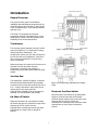
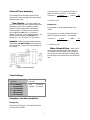
a volt meter (ref. Fig.5 – detailed schematic &
Fig.6 -- meter placement). The following test is
performed using a volt meter set on AC Voltage
with a voltage scale set greater than 24 Volts.
The lid of the hopper should be closed and on its
base and the electronic overflow switch should
not be in the up position.
Connect the meter leads to the terminal board
(TB1) as instructed in the following steps (see
Fig. 6).
1. Connect the meter test leads to terminals 1
and 2 of the TB1. The meter should indicate 24
volts. If the reading is correct go to next step.
Figure 5
electronic overflow switch. The meter should
indicate 24 volts with switch in the up position
and return to zero when released.
If no voltage is present, check the wiring to the
power transformer and verify that power is
present at the outlet that the transformer is
plugged into. If the wiring is correct and the
outlet power is verified then the transformer is
defective and must be replaced.
During the next test, remove power to the
junction box between each step by unplugging
the transformer from the power outlet. Once the
wire is removed from the terminal strip and is
isolated, restore power to the junction box and
perform the test.
If 24 volts is always present during the above
tests the hopper lid switch and/or the electronic
overflow switch may be defective and must be
disconnected from the terminal strip TB1 one at a
time. Refer to Fig. 1 and disconnect the wire to
terminal 3 of TB1. Observe the meter. The 24
volts may or may not return to zero. If the
voltage returns to zero then the lid switch is
defective and must be replaced. If the 24 volts
remain with terminal 3 disconnected leave the
wire to terminal 3 disconnected and perform the
same test with the electronic overflow switch.
Disconnect the wire to terminal 7. Again the 24
volts should return to zero. If not the electronic
over flow switch is defective or is stuck in the
up position. Remove power to the Junction box
and reconnect the wires to terminal 3 and 7.
Figure 6
2. Connect the meter test leads to terminals 1
and 3 of TB1. No voltage should be present.
While observing the meter, lift the lid of the
hopper. The meter should read 24 volts and
return to zero when the lid is replaced.
Lift the hopper off its base. The meter should
indicate 24 volts and return to zero when the
base is replaced.
3. Connect the meter test leads to terminals 5
and 6. If 24 volts is present, but the power light
on the timer module is off, then the timer module
or its wiring is defective. If 24 volts are not
present then the relay RY1 is defective and must
be replaced.
Lift the hopper lid and press down the lid switch.
Reach under the deflection plate and lift the
4