1
Introduction
General Overview
The purpose of this guide is to familiarize
installation and maintenance personnel with the
electrical functions of the Pulsar IV and to assist
in the "troubleshooting" of any electrical failures
that may occur.
The Pulsar IV incorporates six electrical
components and their associated wiring. Each
component is critical in the safe operation and
dispensing of the chlorinated solution.
Transformer:
The electrical system operates from a 24 Volt AC
source provided by a U.L.-listed class-II energylimiting step-down transformer. The
transformer's primary coil (the side connected to
the 120 Volt source) is designed to "open like a
fuse" when the transformer's VA (Volt Amp.)
rating is exceeded.
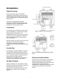
Figure 1 Junction box terminal strip
When the primary coil opens the 24 Volt source is
removed from the secondary electrical
components, preventing over-heating of
components, wiring and possible electrical shock
hazard.
Junction Box:
The transformer, Lid Shut-off Switch , Electronic
Overflow Switch and Solenoid/Timer Assembly
are wired to the junction box terminal strip (Fig. 1
& 2). A relay is mounted in the junction box to
remove the 24 Volt supply from the
Solenoid/Timer Assembly if the chlorinator lid is
removed or if the chlorinator tank overfills.
Figure 2 External wiring Junction Box Terminal
Strip
Electronic Overflow Switch:
When the water level reaches a pre-determined
height in the chlorinator tank the Electronic
Overflow Switch energizes the junction box relay
removing the 24 Volt source from the
Solenoid/Timer Assembly which causes the water
solenoid valve to close (refer to manual for
picture).
Lid Shut-off Switch:
When the chlorinator lid is opened the Lid Shutoff Switch energizes the junction box relay which
removes the 24 Volt source from the
Solenoid/Timer assembly and causes the water
solenoid valve to close (refer to manual for
picture).
1