1
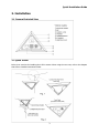
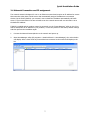
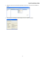
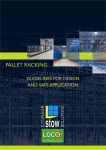
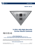
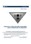
Quick Guide
XX247-20-04
V-CELL High-Security
Corner-Mount Cameras
Vicon Industries Inc.
Tel: 631-952-2288 Fax: 631-951-2288 Toll Free: 800-645-9116
24-Hour Technical Support: 800-34-VICON (800-348-4266) UK: 44/(0) 1489-566300
Vicon Industries Inc. does not warrant that the functions contained in this equipment will meet your requirements or that the
operation will be entirely error free or perform precisely as described in the documentation. This system has not been designed
to be used in life-critical situations and must not be used for this purpose.
www.vicon-security.com
Document Number: 8009-8247-20-04
Product specifications subject to change without notice.
Issued: 214
Copyright © 2014 Vicon Industries Inc. All rights reserved.
Quick Installation Guide
1. Description
The information in this manual provides quick installation and setup procedures for the V-CELL series
of High-Security Corner-Mounted Cameras. These units should only be installed by a qualified
technician using approved materials in conformance with federal, state, and local codes. Read these
instructions thoroughly before beginning an installation. Refer to the complete manual for detailed
information. Always refer to Vicon’s website to assure you have the most up-to-date manual,
http://www.vicon-security.com.
The Roughneck® V-CELL high-security camera is an integrated housing, camera, lens and IR
illuminators system specifically designed for use in custodial suites and prison cells. It is available in
an analog version and IP version that is fully compatible with all ViconNet® systems; its ONVIF
certification provides an open-platform for integration into other video management systems.
The housing is designed to fit into a corner; once installed, the base plate should be permanently
sealed to the wall so that the housing is ligature proof. The housing consists of a two part stainless
steel assembly, a fixed base plate and a removable front plate, that allows ease of installation and
servicing. The front plate is secured with security screws and has two polycarbonate windows to
protect the camera and IR illuminators. The alarm input and alarm output can be used to connect
various third party devices, such as door sensors and alarm bells.
1.1 System Components
The system comes with the following components:
Camera unit
Quick Installation Guide
Installation CD
Accessory Kit
Note: Check your package to make sure that you received the complete system, including all
components shown above.
2
Quick Installation Guide
2. Installation
2.1 Camera Exploded View
2.2 Quick Install
Below is an overview for installing the V-CELL camera. When using the rear cover, refer to the diagram
that follows. Detailed instructions follow.
3
Quick Installation Guide
1. Use camera mounting frame as template to mark mounting holes on mounting surface. (Fig.1)
2. Drill holes for mounting base and a minimum 3/4 in. hole for routing wines. (Fig.1)
3. Mount camera mounting frame using appropriate hardware for mounting surface. (Fig.2)
4. Route wires through hole in wall and out through base plate. (Fig.2).
5. Terminate wires to camera board.
6. Mount front plate to base plate. (Fig.2)
7. When the camera mounting frame is secured to the surface, apply an epoxy security sealant
around the perimeter of the base plate where it meets the ceiling/wall. [Vicon recommends
DynaPoxy™ EP1200 (US) or Arbokol 1025 (UK) or equivalent for this purpose.]
When using rear panel, follow diagram below. Installation of the rear cover is required for
UL/Canadian UL compliance.
1. Use rear cover as template to mark mounting and cable access holes.
2. Drill mounting and cable access holes in mounting surface.
3. Insert cable clamp into access hole, route cables through clamp and mount cover using
appropriate hardware.
4
Quick Installation Guide
4. Use camera mounting frame to mark its mounting holes, drill holes and mount using
appropriate hardware.
5. Terminate wires to camera board. Feed the excess wire back through cable clamp and tighten
clamp.
6. Mount front plate to camera mounting frame.
7. When the camera mounting frame is secured to the surface, apply an epoxy security sealant
around the perimeter of the base plate where it meets the ceiling/wall. [Vicon recommends
DynaPoxy™ EP1200 (US) or Arbokol 1025 (UK) or equivalent for this purpose.]
3. Connections
All cabling is done to the boards located on the back of the front plate. Refer to Figure below.
8-pin terminal block on board.
Pinouts are as follows (printed on the board):
Pin1 : AUDIO OUT
Pin 2 : GND
Pin.3 : AUDIO IN
Pin4 : GND
Pin.5 : ALARM Out
Pin 6 : GND
Pin 7 : ALARM IN( IP Only)
Pin 8 : GND
Analog Connections Refer to previous figure.
1. Connect the power cable to the 2-postion terminal block. The camera accepts 24 VAC or 12 VDC
and polarity is not relevant.
2. Connect the coaxial cable for video output to the BNC connector.
3. To adjust the intensity of the LED illuminators, use the slide switch.
4. Connect the device to the AO (Alarm Out) and G (Ground) terminal block connectors. Alarm Out
can activate external devices such as buzzers or lights. There is no AI (Alarm In). Connect the
Audio In and Out as needed. Pinouts for the terminal block are printed on the board. Refer to
figure above.
5
Quick Installation Guide
Network (IP) Connections
For the operation of the Network Camera, it is necessary to connect a network cable for data
transmission and power connection from supplied power adapter. Depending on operation methods, it
is possible to connect an alarm cable.
•
Connecting to the RJ-45
Connect a standard RJ-45 cable to the network port of the network camera. Generally a
cross-over cable is used for direct connection to PC, while a direct cable is used for connection
to a hub.
•
Connecting Alarms/Audio Refer to previous figure.
AI (Alarm In):
External devices can signal the network camera to react on events. Mechanical or electrical
switches can be wired to the AI (Alarm In) and G (Ground) terminal block connectors.
G (Ground):
Connect the ground side of the alarm input and/or alarm output to the G (Ground) connector.
Alarm Out:
The network camera can activate external devices such as buzzers or lights. Connect the device
to the AO (Alarm Out) and G (Ground) terminal block connectors.
Audio
Connect the Audio In and Out as needed. Pinouts for the terminal block are printed on the board.
•
Connecting Video Output
Video Output is provided for an easy zoom and focus control when adjusting lens.
Connect your Video cable unit to J5 on the board.
•
Connecting the Power
Connect the power of 24 VAC or 12 VDC 1A for the network camera.
Connect the positive (+) pole to the
‘+’
position and the negative (-) pole to
the ‘-’ position. Use certified/Listed Class 2 power source only.
6
Quick Installation Guide
2.4 Network Connection and IP assignment
The network camera is designed for use on an Ethernet network and requires an IP address for access.
Most networks today have a DHCP server that automatically assigns IP addresses to connected
devices. By the factory default, your camera is set to obtain the IP address automatically via DHCP
server. If your network does not have a DHCP server the network camera will use 192.168.1.100 as
the default IP address.
If DHCP is enabled and the product cannot be accessed, run the “Smart Manager” utility on the CD to
search and allocate an IP address to your products, or reset the product to the factory default settings
and then perform the installation again.
1.
Connect the Network Camera/device to the network and power up.
2.
Start SmartManager utility (All programs > NautilusClient16 > SmartManager); the main window
will display. After a short while any network devices connected to the network will display in the
list.
7
Quick Installation Guide
3.
Select the camera on the list and click right button of the mouse. The pop-up menu displays as
below.
4.
Select Assign IP. The Assign IP window displays. Enter the required IP address.
8
Quick Installation Guide
4. Operation
The V-CELL-IP Camera can be used with Windows® operating system and browsers. The
recommended browsers are Internet Explorer®, Safari®, Firefox®, Opera and Google Chrome® with
Windows.
4.1 Access from a browser
1.
2.
3.
Start a browser (i.e., Internet Explorer).
Enter the IP address or host name of the V-CELL-IP Camera in the Location/Address field of your
browser.
A starting page displays. Click Live View or Setup to enter web page.
The camera’s Live View page appears in your browser.
9
Quick Installation Guide
4.2. Access from the Internet
Once connected, the V-CELL-IP Camera is accessible on your local network (LAN). To access the
camera from the Internet you must configure your broadband router to allow incoming data traffic to
the camera. To do this, enable the NAT-traversal feature, which will attempt to automatically
configure the router to allow access to the camera. This is enabled from Setup > System > Network >
NAT.
For more information, see “3.5.4 System>Network>NAT” of User’s Manual.
4.3 Setting the admin password over a secure connection
To gain access to the camera, the password for
the default administrator user must be set. This
is done in the “Admin Password” dialog box,
which is displayed when the network camera is
accessed for setup the first time. Enter your
admin name and password, set by the
administrator.
Note: The default administrator username is
“ADMIN” and password is “1234”. If the
password is lost, the Network Camera must be
reset to the factory default settings. See “4.6
Resetting to the Factory Default Settings”.
4.4 Live View Page
The Live View page comes in several
screen modes, including 704 x 480
(576), 640 x 480, 352 x 240 (288),
and 320 x 240. Users select the most
suitable one for their particular
installation. Adjust the mode in
accordance with your PC
specifications and monitoring
purposes.
10
Quick Installation Guide
1)
General controls
Live View Page
Search & Playback Page
Setup Page
Help Page
The video drop-down list allows you to select a customized or pre-programmed
video stream on the live view page. Stream profiles are configured under Setup > Basic
Configuration > Video & Image. See Basic Configuration in the User manual for more information.
The resolution drop-down list allows you to select the most suitable video
resolution to be displayed on Live View page.
The protocol drop-down list allows you to select which combination of
protocols and methods to use, depending on your viewing requirements and on the properties of
your network.
2)
Control toolbar
The live viewer toolbar is available in the web browser page only. It displays the following
buttons:
The Stop button stops the video stream being played. Pressing the key again toggles the
start and stop. The Start button connects to the network camera or start playing a
video stream.
The Pause button pauses the video stream being played.
The Snapshot button takes a snapshot of the current image. The location where the
image is saved can be specified.
The digital zoom activates a zoom-in or zoom-out function for video image on the live
screen.
The Full Screen button causes the video image to fill the entire screen area. No other
windows will be visible. Press the 'Esc' button on the computer keyboard to cancel full
screen view.
The Manual Trigger button activates a pop-up window to manually start or stop the event.
The Camera Menu button activates a pop-up window for camera menu control.
Use this scale to control the volume of the speakers.
Use this scale to control the volume of the microphone.
Use this scale to control the volume of the speakers and microphones.
3)
Video Streams
The camera provides several images and video stream formats. Your requirements and the
properties of your network will determine the type you use.
The Live View page in the cameras provides access to H.264, MPEG-4 and Motion JPEG video
streams, and to the list of available video streams. Other applications and clients can also access
these video streams/images directly, without going via the Live View page.
11
Quick Installation Guide
4.5 Network Camera Setup
This section describes how to configure the V-CELL-IP Camera. It is intended for Administrators, who
have unrestricted access to all the Setup tools, and Operators, who have access to the settings for
Basic, Live View, Video & Image, Event, and System Configuration.
You can configure the V-CELL-IP Camera by clicking Setup in the top right-hand corner of the Live
View page. Click on this page to access the online help that explains the Setup tools.
When accessing the V-CELL-IP Camera for the first time,
the “Admin Password” dialog appears. Enter your admin
name and password, set by the administrator.
Note: If the password is lost, the V-CELL-IP Camera
must be reset to the factory default settings.
See “4.6 Resetting to the Factory Default Settings”.
4.6 Resetting to the factory default settings
To reset the V-CELL-IP Camera to the original factory settings, go to the Setup>System >Maintenance
web page (described in “3.5.4 System>Maintenance” of the User’s Manual) or use the control button
on the V-CELL-IP Camera, as described below:
Follow the instructions below to reset the Network Camera to the factory default settings using the
Reset Button.
1.
2.
3.
4.
5.
6.
7.
Switch off the V-CELL-IP Camera by disconnecting the power adapter.
Open the lens cover.
Press and hold the Control Button (SW1) on the board with your finger while reconnecting
the power.
Keep the Control button (SW1) pressed for about 2 seconds.
Release the Control Button (SW1).
The V-CELL-IP Camera resets to factory defaults and restarts after completing the factory reset.
The unit now obtains the IP address automatically via DHCP.
Close the lens cover.
CAUTION: When performing a Factory Reset, any previously saved settings will be lost.
4.7 More Information
For more information, see the V-CELL-IP Camera User’s Manual, which is available on the CD included
in this package.
12
Vicon Industries Inc.
For office locations, visit the website:
www.vicon-security.com