1
7 TRANSMISSION MODULE
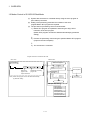
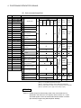
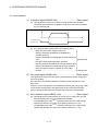
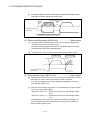
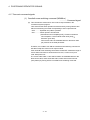
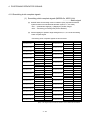
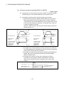
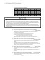
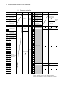
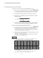
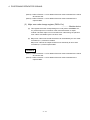
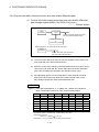
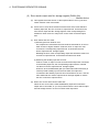
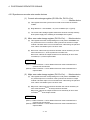
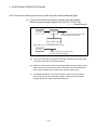
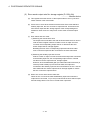
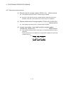
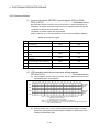
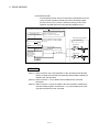
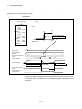
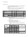
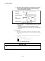
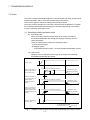
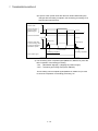
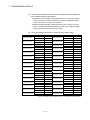
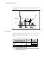
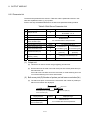
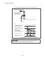
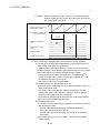
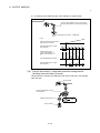
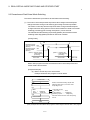
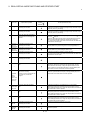
(d) Refer to APPENDIX 5 for the refresh cycle of clutch status signal.
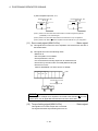
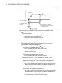
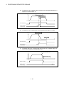
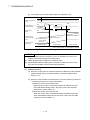
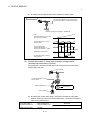
ON
OFF
Clutch ON/OFF
command device (Note)
ON
Clutch status
signal
OFF
Maximum
1 operation cycle
Maximum
1 operation cycle
Current value of
virtual axis (input
axis)
Maximum
1 operation cycle
Continuance from
current value at
clutch OFF
Current value of
output axis
Clutch OFF state
Clutch ON state
Clutch OFF state
Continuance from
current value at
clutch OFF
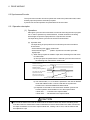
(Note) : Refer to Section "7.2.2 Parameters" for details.
Fig. 7.2 Operation Timing for ON/OFF Mode
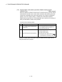
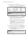
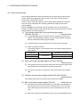
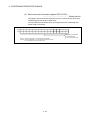
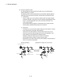
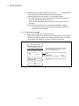
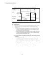
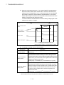
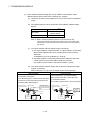
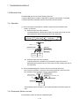
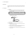
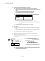
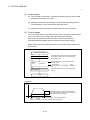
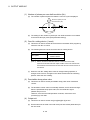
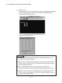
(2) Address mode
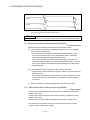
(a) When the current value of virtual axis reaches an address of clutch ON/OFF
address setting device, the clutch ON/OFF is executed. (Mode setting
device is "1".)
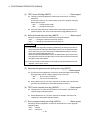
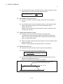
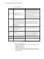
1) When the clutch ON/OFF command device is ON and the current value
of virtual axis reaches an address set in the clutch ON address setting
device, the clutch is set to the ON state.
2) When the clutch ON/OFF command device is OFF and the current value
of virtual axis reaches an address set in the clutch OFF address setting
device, the clutch is set to the OFF state.
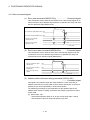
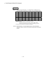
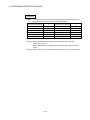
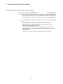
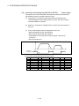
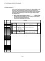
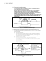
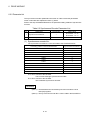
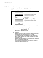
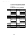
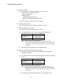
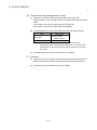
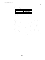
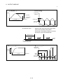
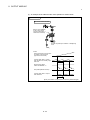
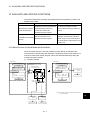
(b) The clutch ON/OFF control differs according to the output module connected
as follows.
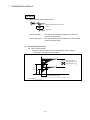
1) For a ball screw or roller
The ON/OFF control is executed by the current value of virtual axis.
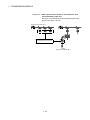
When a differential gear is connected to the main shaft, the ON/OFF
control is executed by the current value after the main shaft's differential
gear.
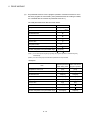
2) For a rotary table or cam
The ON/OFF control is executed by the current value within 1 virtual axis
revolution.
(Refer to a rotary table or cam of output module for details.)
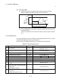
7 - 13