1
MITSUBISHI ELECTRIC
GX Configurator-DP 7.08J
Configuration System
for Open Networks
Software Manual
Art.no.: 65778
December 2012
Revision a
MITSUBISHI ELECTRIC INDUSTRIAL AUTOMATION
About this Manual
The texts, illustrations, diagrams and examples in this manual are only
intended as aids to help explain the functioning, operation, use and
programming of the open network configuration system
MELSOFT GX Configurator-DP.
Separate manuals are available for MITSUBISHI ELECTRIC's various
series of MELSEC programmable logic controllers.
This manual is only intended for users with experience in handling
automation and communication networks.
For using and usage of this software only the user his own is responsible.
If you have any questions regarding the installation and operation of the
software described in this manual, please do not hesitate to contact your
sales office or one of your MITSUBISHI ELECTRIC distribution partners.
You can also obtain information and answers to frequently asked questions
from our MITSUBISHI ELECTRIC website under
www.mitsubishi-automation.com.
The GX Configurator-DP software is supplied under a legal license
agreement and may only be used and copied subject to the terms of this
License Agreement.
No part of this manual may be reproduced, copied, stored in any kind of
information retrieval system or distributed without the prior express written
consent of MITSUBISHI ELECTRIC.
MITSUBISHI ELECTRIC reserves the right to change the specifications of
its products and/or the contents of this manual at any time and without
prior notice.
The IEC 61131.1 standard cited in this manual is available from the
publishers Beuth Verlag in Berlin (Germany).
© 2012 MITSUBISHI ELECTRIC CORPORATION
Revisions
Print Date
Revision
Content
August 2005
-
GXDP 7.00A
August 2006
-
GXDP 7.01B
April 2007
-
GXDP 7.02C
May 2009
-
GXDP 7.03D
December 2009
-
GXDP 7.04E
July 2010
-
GXDP 7.05F
January 2011
-
GXDP 7.06G
April 2011
-
GXDP 7.07H
May 2012
-
GXDP 7.08J
November 2012
a
Description of QnPRH support added
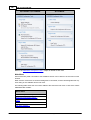
Contents
I
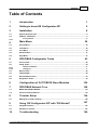
Table of Contents
1
Introduction
1
2
Getting to know GX Configurator-DP
2
3
Installation
8
3.1
System
...................................................................................................................................
Requirements
8
3.2
Software
...................................................................................................................................
Installation
9
3.2.1
Getting Started
......................................................................................................................................................... 16
24
4
Main Menu
4.1
Project
...................................................................................................................................
Menu
25
4.2
Tools
...................................................................................................................................
Menu
38
4.3
View
...................................................................................................................................
Menu
39
4.4
Window
...................................................................................................................................
Menu
41
4.5
Help
...................................................................................................................................
Menu
41
5
PROFIBUS Configurator Tasks
5.1
Online
...................................................................................................................................
Tasks
45
5.2
Setup
...................................................................................................................................
Tasks
60
43
GSD Device
.........................................................................................................................................................
Database
65
I/O Mapping
......................................................................................................................................................... 74
5.2.1
5.2.2
5.3
Export
...................................................................................................................................
Tasks
85
5.4
Import
...................................................................................................................................
Tasks
89
5.5
Documentation
...................................................................................................................................
Tasks
93
5.6
Diagnostics
...................................................................................................................................
Tasks
95
6
Configuration of QJ71PB93D Slave Modules
105
7
PROFIBUS Network Tree
108
7.1
Master
...................................................................................................................................
Parameters Wizard
110
7.2
Slave
...................................................................................................................................
Parameters Wizard
119
8
Transfer Setup
8.1
Editing
...................................................................................................................................
the Transfer Settings
138
9
Using 'GX Configurator-DP' with 'GX Works2'
9.1
Integrated
...................................................................................................................................
Version
147
9.2
Standalone
...................................................................................................................................
Version
191
10
Troubleshooting
(c) 2012 MITSUBISHI ELECTRIC CORPORATION
134
147
196
II
GX Configurator-DP
Index
197
(c) 2012 MITSUBISHI ELECTRIC CORPORATION
Introduction
1
1
Introduction
This manual...
...is a compact guide to using GX Configurator-DP software suitable both for beginners and experienced users upgrading from other systems. The manual includes explanations of the terms and
structural concepts about the software and the configuration of an open network system. The manual
provides a precise step-by-step description of how to use GX Configurator-DP including sample projects. These executable application is used to demonstrate the operation of the program with the
help of the examples provided in this manual. The PLC series MELSEC Q Series is referenced as
MELSEC system Q in this manual.
If you are not yet familiar with MS Windows...
... please at least read the Windows Fundamentals section in the Windows User's Guide, or work
through the Windows Tutorial accessible through the Help menu of the Windows Program Manager.
This will teach you what you need to know about using the basic elements of Microsoft ® Windows,
and the operating procedures that are identical in all Windows application programs.
If you have problems with parameter settings, ...
... please refer to the user´s manuals of the concerning open network modules.
If you get stuck...
... do not despair, help is never far away! If you run up against seemingly insoluble problems, or if
you have questions about GX Configurator-DP or the connected programmable logic controller (PLC)
configuration, please first refer to the manuals and documentation. Many answers and solutions can
also be found directly in the GX Configurator-DP context-sensitive online help system, which can always be accessed by pressing the <F1> key. If you cannot find answers to your questions in any of
these places, contact your local MITSUBISHI ELECTRIC representative or call our European
headquarters in Ratingen directly.
(c) 2012 MITSUBISHI ELECTRIC CORPORATION
2
2
GX Configurator-DP
Getting to know GX Configurator-DP
GX Configurator-DP Concept
GX Configurator-DP (GXDP) is the configuration tool for PROFIBUS interfaces in MITSUBISHI PLCs.
It provides functions for defining a PROFIBUS network, validating the configuration and downloading
it to the respective PLC module via a MITSUBISHI automation network.
GX Configurator-DP is capable of downloading configuration data to the PROFIBUS module via a variety of different communication types. The module can be located in a PLC rack directly connected
to the PC or in a PLC rack, which is connected to other PLCs in a separate network.
GX Configurator-DP takes information on PROFIBUS DP slaves from GSD files, which are specific to
the respective slave and usually provided by the slave hardware vendor. It generates program code
for use in GX Works2 (GXW2) and GX IEC Developer (GID).
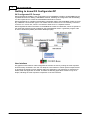
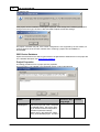
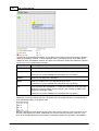
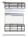
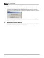
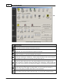
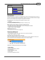
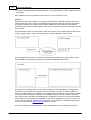
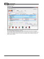
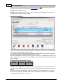
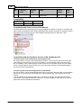
User Interface
The graphical user interface of GX Configurator-DP assists the user by making the most important
functions easily accessible. The user can adapt the user interface to his/her personal requirements
by arranging the specific function windows within the application. This placement is stored and reloaded, when the application is started. Therefore the following application window is only an example, indicating the most important components of the user interface.
(c) 2012 MITSUBISHI ELECTRIC CORPORATION
Getting to know GX Configurator-DP
3
The main items of the user interface are
·
application window
·
main menu
·
toolbar
·
status bar
·
about box
GX Configurator-DP cannot simultaneously be started multiple times on the same computer. Trying
to start GX Configurator-DP again, while it is already running, brings the existing instance of GX
Configurator-DP in the foreground. The GX Configurator-DP application can however have several projects open at the same time.
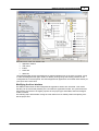
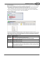
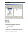
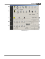
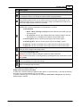
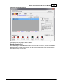
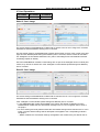
Modifying the User Interface
The different views within the GX Configurator-DP application window are ‘dock-able’. This means
that they can be moved and placed by the user within the application window. The opens views and
their position are stored in the registry specific for the project type and loaded, when GX Configurator-DP is started.
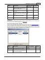
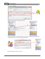
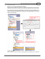
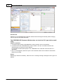
The following steps demonstrate moving the ‘Task Panel’ from its default position and placing it below the project tree.
(c) 2012 MITSUBISHI ELECTRIC CORPORATION
4
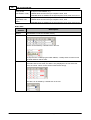
GX Configurator-DP
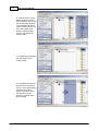
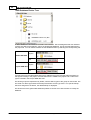
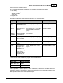
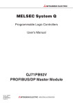
1. place the mouse cursor on
the caption of the window,
which should be moved, and
press the left mouse button
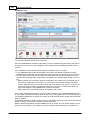
2. move the mouse cursor
while keeping the mouse button pressed. This causes the
‘docking pane stickers’ to be
displayed. These blue arrows
indicate, where the window
could be placed
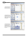
3. move the mouse cursor
onto the bottom docking arrow. The area, where the window would be docked, is
marked with a blue rectangle.
Release the mouse button to
place the window at the indicated position
(c) 2012 MITSUBISHI ELECTRIC CORPORATION
Getting to know GX Configurator-DP
5
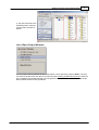
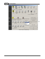
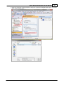
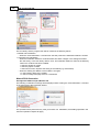
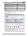
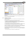
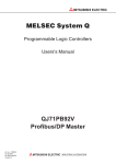
4. the window (here the task
panel) is now displayed below
the project tree. Both project
tree and task panel have
been moved to the left edge
of the application window,
which was previously occupied by the task panel.
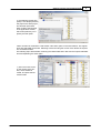
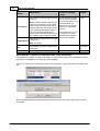
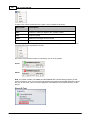
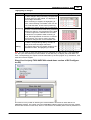
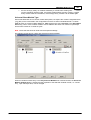
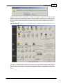
Views can also be combined in a tab window. This saves space in the user interface. The original
views are selectable via the tabs. Selecting a tab and moving the mouse cursor allows the separation of tabbed windows.
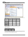
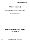
The following steps demonstrate combining the ‘Global GSD data’ view with the ‘Project GSD data’
view and separating the views again.
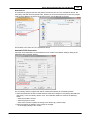
1. place the mouse cursor
on the caption of the window, which should be
moved, and press the left
mouse button
(c) 2012 MITSUBISHI ELECTRIC CORPORATION
6
GX Configurator-DP
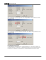
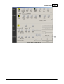
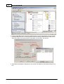
2. move the mouse cursor
while keeping the mouse
button pressed. This causes
the ‘docking pane stickers’
to be displayed. Move the
mouse cursor onto the button in the middle, which
shows a tabbed window
symbol, and release the
mouse button
3. an additional tab appears
with the caption of the
moved window
4. to separate the views select the tab and move the
mouse cursor while keeping
the left mouse button
pressed. The area, where
the window would be
docked, is marked with a
blue rectangle.
(c) 2012 MITSUBISHI ELECTRIC CORPORATION
Getting to know GX Configurator-DP
7
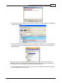
5. The view is docked at the
indicated position, after the
mouse button has been released
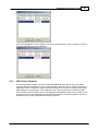
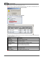
List of Open Project Windows
The list of open docking windows for the active project can be opened by pressing Alt+F7. The user
can select a window in this list with the cursor keys while k eeping the Alt button pressed. When the
key is released, the window selected in the list gets the focus. This allows to move between the different windows without mouse operations.
(c) 2012 MITSUBISHI ELECTRIC CORPORATION
8
3
GX Configurator-DP
Installation
Before You Begin
Copyright
Important Notice:
This software is protected by copyright. By opening the distribution disks package
you automatically accept terms and conditions of the license agreement.
You are only permitted to make one single copy of the original distribution disks for your
own backup and archiving purposes.
Software Purpose
This software is a configuration utility software package which will be used to configure
PROFIBUS DP network interface modules of MELSEC System Qn, QnA, A and FX series' PLCs
such as:
· PROFIBUS DP master module A(1S)J71PB92D
· PROFIBUS DP master module QJ71PB92D
· PROFIBUS DP V1/V2 master module QJ71PB92V
· PROFIBUS DP V1 master module FX3U-64DP-M
· PROFIBUS DP slave module QJ71PB93D
If GX Configurator-DP is used integrated in GX Works2, only the Q-series PROFIBUS master and
slave modules are supported.
3.1
System Requirements
To install the GX Configurator-DP software package your computer has to meet the following requirements
Minimum Hardware Requirements
·
·
·
·
·
·
·
·
·
Pentium II 350 Mhz processor (for Vista/7: 1 GHz processor)
128 MB RAM for Microsoft ® Windows 2000
256 MB RAM for Microsoft ® Windows XP
1 GB RAM for Microsoft ® Windows Vista/7
VGA compatible graphics adapter
17"/43 cm diag. VGA monitor
At least 200 MB free hard disk space
CD-ROM drive
interface for communication with the PLC system
Software Requirements
GX Configurator-DP is a 32-bit software that runs on the following operating systems
· Microsoft ® Windows 2000 (Service Pack 2 or later installed)
· Microsoft ® Windows XP Home or Professional Edition (min. SP2)
· Microsoft ® Windows Vista Home (or higher)
· Microsoft ® Windows 7 (32- and 64 bit) Home (or higher)
Related MELSOFT Software
GX Configurator-DP is typically used together with one of the PLC programming packages for
MITSUBISHI PLCs
· 'GX Works2' (GXW2)
· 'GX Developer' (GD)
· 'GX IEC Developer' (GID)
(c) 2012 MITSUBISHI ELECTRIC CORPORATION
Installation
9
Certain functions of GX Configurator-DP are restricted or not available for specific PLC programming
packages.
'GX Developer' (GD)
· PLC code generated with 'POU Generation' uses 'IEC Instruction Language' (IL) and cannot be imported in GD
'GX Works2' (GXW2)
The standalone version of GX Configurator-DP faces the following restrictions with regard to GX
Works2:
· the path to a GX Works2 project cannot be assigned in 'Project Properties'.
· 'Autorefresh Update' is not supported for a GX Works2 project; autorefresh settings can only be
updated in the CPU.
· the standalone version of GX Configurator-DP cannot update autorefresh settings on a Q-series
Remote I/O. Therefore either the integrated version of GX Configurator-DP is required or the
PROFIBUS modules must be placed in the rack of the control CPU instead of the rack of the Remote I/O.
· import of the PLC code for I/O mapping requires a GX Works2 version with support for the 'IL' programming language. This is only available in the 'European version' of GX Works2 from version
1.87R or newer.
Beginning with version ‘7.08J’ GX Configurator-DP can be started from within the GX Works2 application for Q-series PLC projects. The integrated version of GX Configurator-DP faces the following restrictions when started in GX Works2:
· PLC code generation 'POU Generation' is not possible with a 'simple' GX Works2 project.
· the 'POU Generation' function requires support for the 'IL' programming language, which is only
available in 'European' versions of GX Works2.
Note: Integration of GX Configurator-DP in GX Works2 requires GX Works2 version 1.87R or newer.
3.2
Software Installation
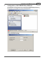
Installing for GX Works2 Integration
GX Works2 must be installed before GX Configurator-DP is installed in order to create the correct
system settings.
The following list of installation scenarios describes the effects on the use of the integrated GX Configurator-DP within GX Works2.
1. Case
· GX Configurator-DP 7.08J is installed at first
· GX Works2 version 1.87R or newer is installed after GX Configurator-DP
--> The integrated behaviour of GX Configurator-DP is not enabled. The installer cannot add
PROFIBUS DP modules to the Intelligent Function Module selection dialog of GX Works2.
2.
·
·
·
·
Case
GX Works2 version 1.87R or newer is installed
GX Configurator-DP 7.08J is installed.
GX Configurator-DP 7.08J is de-installed
GX Configurator-DP 7.07H is installed
--> If GX Configurator-DP 7.08J is de-installed, the PROFIBUS DP modules are removed from the Intelligent Function Module selection dialog of GX Works2. If GX Configurator-DP 7.07H is installed,
the PROFIBUS DP modules in the Intelligent Function Module selection dialog of GX Works2 are not
available. The integrated behaviour of GX Configurator-DP is not available.
(c) 2012 MITSUBISHI ELECTRIC CORPORATION
10
GX Configurator-DP
3.
·
·
·
Case
GX Works2 version 1.87R or newer step is installed
GX Configurator-DP 7.08J is installed.
GX Configurator-DP 7.08J is de-installed
--> The integrated behaviour of GX Configurator-DP is not available. All menu items visible for
PROFIBUS DP modules have been removed from GX Works2.
GX Configurator-DP Setup
To install the GX Configurator-DP software you need to have Microsoft ® Windows properly installed.
You may require administrator privileges when installing the software.
If an older version of GX Configurator-DP is already installed, uninstall it first. After the de-installation
please start the installation of the new version. If you want to keep the older version of GX Configurator-DP, please select a different directory for the new version. A de-installation of the older version,
after the newer version has been installed, will also damage the newer version. Therefore please reinstall the new version after uninstalling both the older and the newer GX Configurator-DP versions, if
you encounter problems. Please stop all other running software before the installation and do not run
other installation programs during the installation of GX Configurator-DP.
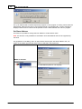
Installing GX Configurator-DP (incl. GX Configurator-ST)
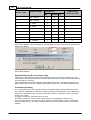
To start the installation, proceed as follows:
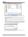
1. Insert the installation CD-ROM into your CD-ROM drive.
2. If you have 'Autorun' enabled for the drive, the setup should start automatically.
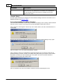
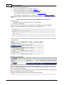
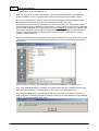
3. If the setup is not started automatically, please locate the 'setup.exe' file and execute it.
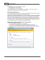
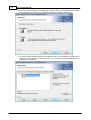
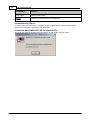
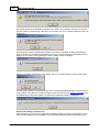
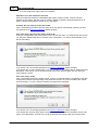
4. If you see the following message on a Windows ® Vista/Win7 operating system, please select 'Allow'
(c) 2012 MITSUBISHI ELECTRIC CORPORATION
Installation
11
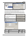
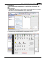
5. Follow the given instructions that guide you through the installation procedure. Continue with
Next.
(c) 2012 MITSUBISHI ELECTRIC CORPORATION
12
GX Configurator-DP
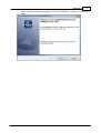
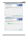
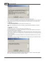
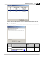
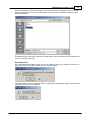
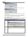
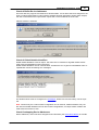
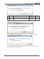
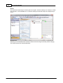
6. The licensing agreement is displayed. Please read these terms carefully. If you accept the license agreement, you can proceed with the installation by clicking Next. Otherwise the installation is aborted.
Note: This dialog is only shown for European product versions.
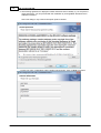
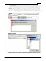
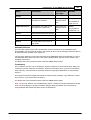
7. Enter your name, organization and the product serial number. Click on Next to proceed.
(c) 2012 MITSUBISHI ELECTRIC CORPORATION
Installation
13
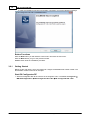
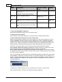
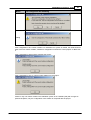
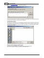
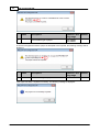
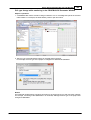
8. Enter the destination folder where you want the GX Configurator-DP software to be installed
(default C:\Melsec\GX Configurator-DP 7.08J). If you agree with the default setting, just
click on Next.
9. If you want to install to a different directory, click on Change and select the installation directory.
(c) 2012 MITSUBISHI ELECTRIC CORPORATION
14
GX Configurator-DP
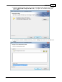
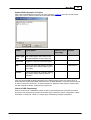
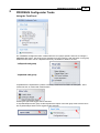
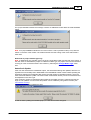
10. You can choose between a 'Complete' and a 'Custom' setup. The 'Complete' setup installs
all components, the 'Custom' setup allows the selection of optional components.
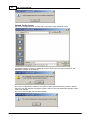
11. If 'Custom' setup has been selected in the previous step, the components are listed. By selecting the icon to the left of a component name, you can select respectively deselect the installation of a component.
(c) 2012 MITSUBISHI ELECTRIC CORPORATION
Installation
15
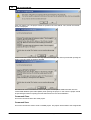
12. The installation is started by pressing the Install button.
13. After pressing the 'Install' button the installation is started. Progress bars will inform you
about the setup status.
(c) 2012 MITSUBISHI ELECTRIC CORPORATION
16
GX Configurator-DP
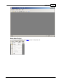
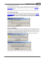
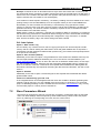
14. After the installation has been successfully completed, you see the following message
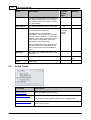
Button Functions
With the Next button you will leave the current menu and enter the next menu.
With the Back button you go to the previous window.
Cancel button ends the installation procedure.
3.2.1
Getting Started
Below are the main steps, which are required to configure a PROFIBUS DP master module. The
QJ71PB92V module is used as an example.
Start GX Configurator-DP
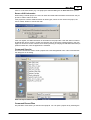
1. Start GX Configurator-DP via the shortcut in the Programs menu. The default is Programs g
MELSOFT Application g GX Configurator-DP 7.08J g GX Configurator-DP 7.08J.
(c) 2012 MITSUBISHI ELECTRIC CORPORATION
Installation
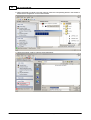
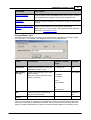
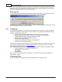
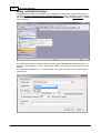
Start a New Project
1. in the main menu Project select New to open a new project file.
(c) 2012 MITSUBISHI ELECTRIC CORPORATION
17
18
GX Configurator-DP
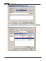
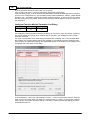
2. select the PROFIBUS module, which should be configured
If the module to be configured exists already in a connected PLC, you can select the module online
by pressing 'Read from PLC'. After configuring the connection to the PLC, the list of modules is displayed
(c) 2012 MITSUBISHI ELECTRIC CORPORATION
Installation
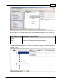
19
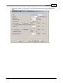
3. enter master settings, e.g. starting I/O number and select the baud rate of the PROFIBUS network
(c) 2012 MITSUBISHI ELECTRIC CORPORATION
20
GX Configurator-DP
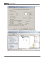
4. enter the buffer device addresses in the CPU for the data exchanged with the PROFIBUS module
5. add the slave devices from the GSD database tree to the project tree with drag&drop
(c) 2012 MITSUBISHI ELECTRIC CORPORATION
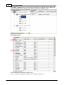
Installation
21
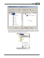
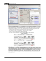
6. configure each slave device e.g. the FDL address, selected modules and user parameters
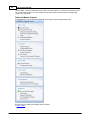
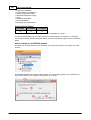
7. if the slave does not yet exist in the GSD database, add the GSD file of the slave to the global
GSD database. Select the 'Global GSD data' tree and select the item 'Add Slave' from its context
menu. In the file dialog select the GSD file. After the GSD file has been parsed, the slave type is
added to the database and a new node is added to the tree.
(c) 2012 MITSUBISHI ELECTRIC CORPORATION
22
GX Configurator-DP
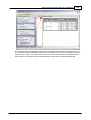
8. select 'Download to module' in the task panel or press the corresponding button in the toolbar to
download the configuration to the master module
9. create the program code by selecting 'POU Generation'
(c) 2012 MITSUBISHI ELECTRIC CORPORATION
Installation
10. import the POU in the GID project
(c) 2012 MITSUBISHI ELECTRIC CORPORATION
23
24
4
GX Configurator-DP
Main Menu
Starting GX Configurator-DP
Select GX Configurator-DP from the Windows Start menu. The default shortcut is
Start -> Programme -> MELSOFT Anwendungen -> GX Configurator-DP 7.08J -> GX Configurator-DP 7.08J
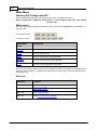
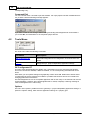
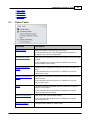
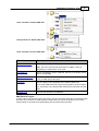
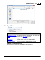
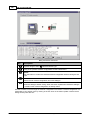
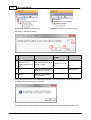
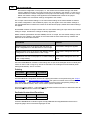
Main menu
The main menu offers the following pull-down menus. The menu item Window is only available, if a
project is open.
if no project is open
if a project is open
Main Menu
Items
Description
Project
menu for creating, opening and saving project files
Tools
menu for external tools
View
menu for configuration of the application
Window
menu for listing the open project windows
Help
menu for help and application information
The items in the open pull-down menus can be reached via mouse or keyboard. The underlined character will start the function. In addition there are some menu items which may be started using predefined hot keys.
Shortcuts
Shortcut
Function
Ctrl + 'N'
create new project
Ctrl + 'O'
open existing project
Ctrl + 'S'
save modified projects
Alt + F7
show list of open project windows
(c) 2012 MITSUBISHI ELECTRIC CORPORATION
Main Menu
4.1
25
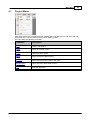
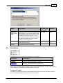
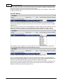
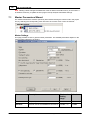
Project Menu
After having started the GX Configurator-DP software, this is the first menu to work with. With the
help of this menu you can create a new or load an existing project.
The menu offers the following commands:
Command
Description
New
Starts a new project
Open
Opens an existing project
Close
Closes the active project
Save
Saves the active modified project
Save As
Saves the active project under a new name
Recent Files
Opens one of the latest used projects
Exit
Ends the application
(c) 2012 MITSUBISHI ELECTRIC CORPORATION
26
GX Configurator-DP
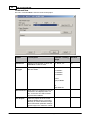
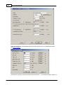
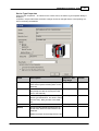
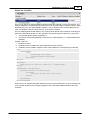
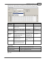
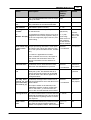
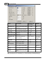
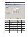
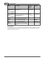
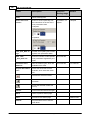
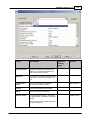
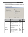
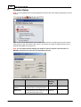
Command New
The menu command New is used to create a new project.
Name
Description
Choices / Setting
range
CPU Series
selection of CPU series, in which the
PROFIBUS module is used
Qn, QnA/A, FX
MELSEC Module Type
module types supported by the selec- Qn:
ted CPU series
QJ71PB92V
Default
Qn
QJ71PB92V
QJ71PB92D
QJ71PB93D
QnA/A:
A(1S)J71B92D
FX:
FX3U-64DP-M
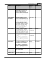
Read from PLC reads the list of modules from the connected PLC and displays them in a
list, so the user can select module
type and head address
-
PLC Project
-
select the project file of the corresponding GD/GID project. The project
directory is used to locate the image
file for autorefresh parameter settings
(iparam.wpa) in the ‘Resource’ subdir-
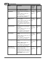
(c) 2012 MITSUBISHI ELECTRIC CORPORATION
Main Menu
Name
Description
Choices / Setting
range
27
Default
ectory of the GD/GID project. This file
is updated by GXDP, if the ‘Autorefresh’-option has been selected
Browse
opens the file dialog to select the GD/
GID project file
max. 255 characters
-
Comment
an optional comment text of max. 255 max. 255 characters
characters length, which describes
the project
-
Cancel
close the dialog and discard changes
-
Next
proceeds to next wizard page
Default button
Default
sets CPU series and module type to
their default settings, clears PLC project path and comment field
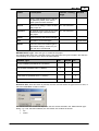
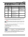
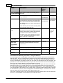
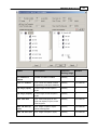
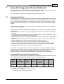
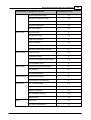
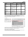
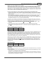
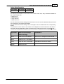
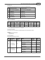
MELSEC Module Type: select the type of module for the project
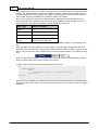
The following table shows the supported project types and marks the types included in the selection
list depending on the type of PLC, which has been selected.
Module Type
Qn
A(1S)J71PB92D (PROFIBUS DP V0 Master)
FX
x
QJ71PB92D (PROFIBUS DP V0 Master)
x
QJ71PB92V (PROFIBUS DP V1/V2 Master)
x
FX3U-64DP-M (PROFIBUS DP V1 Master)
QJ71PB93D
QnA/A
x
x
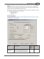
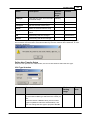
Read from PLC: when this button is pressed, the user must first select the type of the PLC CPU, in
which the PROFIBUS module is located.
The entries in the ‘CPU series’ list depend on the CPU series selected in the ‘Select Module Type’
dialog, e.g. if ‘Qn’ has been selected, the ‘CPU Series’ list contains the entries
·
Qn
·
QnPH
(c) 2012 MITSUBISHI ELECTRIC CORPORATION
28
GX Configurator-DP
·
QnPRH
·
QnU
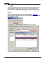
The list ‘CPU type’ contains the CPU types of the selected series. Pressing the button ‘Transfer
Setup’ in the dialog ‘CPU Type Selection’ opens the transfer setup dialog. When this dialog is
closed by pressing ‘OK’, the latest transfer settings are always stored in the same file in the GX
Configurator-DP installation directory. These settings are used as default for the next new project, if
the CPU series stays the same. If the CPU series is changed, e.g. by first creating a QJ71PB92V
project and then a project for the FX3U-64DP-M, the transfer setup is converted to match the new
CPU series.
After this the transfer setup editor is opened, so the user can adjust the settings of the PLC connection. For a detailed description of the transfer setup dialogs see the section ‘Transfer Setup’.
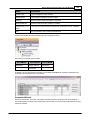
After leaving the transfer setup editor, a connection to the PLC is attempted. If the connection fails,
an error message is displayed.
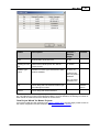
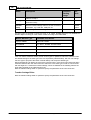
If the connection can be established, the list of modules in the PLC rack is displayed.
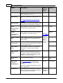
(c) 2012 MITSUBISHI ELECTRIC CORPORATION
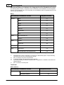
Main Menu
29
Name
Description
Choices /
Setting
range
Default
Slot
0-based index of the PLC slot
0 - 63
-
Starting I/O number
offset of the module-specific X/Y devices
(empty for FX)
0 - 0xFE0
-
Module Typename
identifier of module type retrieved from GXDP
product database
A, QnA, FX:
-
module types
found in product
database
Qn: type name
read from PLC
OK
Close dialog and save selected module type
and starting I/O number
Default
button
Cancel
Close dialog and discard selection
-
If the user selects a module supported by GXDP, the corresponding module type is set in the combo
box. The starting I/O number of the selected module is used as default for the starting I/O number of
either master or slave instead of the default I/O number 0x00.
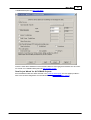
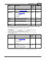
'New Project Wizard' for Master Projects
If a master module has been selected in the previous wizard page, the next pages provide access to
the master configuration and are identical to the 'Master Parameters Wizard'.
(c) 2012 MITSUBISHI ELECTRIC CORPORATION
30
GX Configurator-DP
Select the baudrate for the PROFIBUS network and other parameters. For a detailed description
see Master Settings
This dialog is opened by pressing the button ‘Bus Parameters…’ in the ‘Master Settings’ dialog. For
(c) 2012 MITSUBISHI ELECTRIC CORPORATION
Main Menu
31
a detailed description see Bus Parameters.
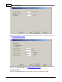
Enter the CPU device addresses of the transfer buffers for exchanging data between CPU and master module. For a detailed description see CPU Device Access
'New Project Wizard' for QJ71PB93D Projects
If a QJ71PB93D module has been selected in the previous wizard page, the next pages provide access to the Q-slave configuration and are identical to the 'Slave Parameters Wizard'.
(c) 2012 MITSUBISHI ELECTRIC CORPORATION
32
GX Configurator-DP
Enter the starting I/O number and the FDL address of the slave module. For a detailed description
see Q-Slave PROFIBUS Settings.
Enter the CPU device addresses of the transfer buffers for exchanging data between CPU and slave
module. For a detailed description see Q-Slave Autorefresh Settings.
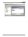
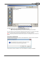
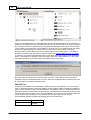
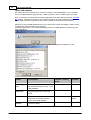
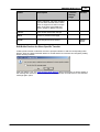
Command Open
The menu command Open allows to open a project, which has previously been saved.
(c) 2012 MITSUBISHI ELECTRIC CORPORATION
Main Menu
33
The Open dialog box lists only files of the following type:
· *.dp2: old or current GX Configurator-DP project file format
· *.dpx: old GX Configurator-DP project file format for QJ71PB93D slave modules
The current version can open project files created with previous versions 4.0 or newer of GX Configurator-DP. Previous versions cannot open GX Configurator-DP 7.08J project databases.
Note: *.DP-projects generated with software versions previous to GX Configurator-DP 4.0 cannot be
opened.
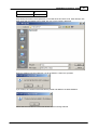
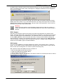
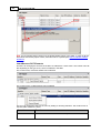
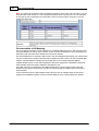
Conversion of Old Projects
If a project file created with an older version of GX Configurator-DP is opened, the user is informed
that the file must be converted.
If the project file cannot be converted, a list of more detailed error messages is displayed.
(c) 2012 MITSUBISHI ELECTRIC CORPORATION
34
GX Configurator-DP
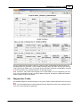
The error messages can be saved in an ASCII file by selecting the 'Save' button.
If the conversion of a PROFIBUS master project fails, missing GSD information is in most cases the
reason. GX Configurator-DP searches the following files for GSD information in the following order:
1. project file
2. global GSD device database
3. GSD export file (same file name as the project, but extension '.ext')
If the option 'GSD database has priority' is enabled, the global GSD device database is searched
first:
1. global GSD device database
2. project file
3. GSD export file (same file name as the project, but extension '.ext')
The second sequence may be helpful in rare situations, where the GSD information in the project is
inconsistent with the project configuration.
If a slave type, specified by a combination of the GSD entries 'Model_Name', 'Ident_Number' and 'Revision', cannot be found in any of the three files, the conversion stops and the error message lists the
missing slave types.
The user should add the corresponding GSD files to the global device database and retry to convert
the project file.
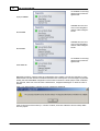
If the project file could be converted, but settings had to be changed, the user can review the actions
taken during the conversion in a list.
Note: the converted project overwrites the old project file, when it is saved. To preserve the original
file, a copy of the file with the extension '.backup' is created.
(c) 2012 MITSUBISHI ELECTRIC CORPORATION
Main Menu
35
Update GSD Information in Project
If the option 'GSD database has priority' has been selected in 'Options', the user can select slave
types, which exist in both the project file and the GSD database.
Name
Description
Choices / Setting range
Default
Slave Type
List
list of slave types, which exist in both
the GSD database and the project file
Select All
toggles the selection of the slave types
OK
closes the dialog and replaces the GSD
information of the selected slave types in
the project
Default button
Cancel
closes the dialog and continues opening
the project without replacing GSD information
-
If the user presses OK, the GSD information for the selected slave types in the project file is replaced with the corresponding GSD information from the GSD database. If the user presses 'Cancel'
or does not select any slave type, no GSD information is updated and the project is opened using
the GSD information already contained in the project file.
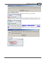
Check of GSD Consistency
When a project file for a PROFIBUS master is opened, GX Configurator-DP searches the GSD information in the project file for the slave and module types used in the project configuration. If GSD
information is missing for a slave or a module type, the following message is displayed.
(c) 2012 MITSUBISHI ELECTRIC CORPORATION
36
GX Configurator-DP
If the user selects ‘No’, the project cannot be opened. If the user selects ‘Yes’, the list of inconsistencies is displayed.
If errors have been found, the user can only view the messages, but cannot proceed with opening the
project. The ‘OK’ button is therefore disabled.
The reason for such inconsistencies can be an import of incompatible GSD information from the
central GSD database (see ‘GSD Update’) when opening the project. In this case the project should
be opened again without importing the GSD information from the central database.
Command Close
This menu command closes the active project.
Command Save
This menu command is used to save a modified project. The project will be saved to the assigned file
(c) 2012 MITSUBISHI ELECTRIC CORPORATION
Main Menu
37
name. If no file name exists (e.g. new project) the standard dialog box for Save As will be opened.
Remove GSD Information
When saving a master project, the user can have all unused GSD information removed from the project file in order to reduce its size.
If the project file contains GSD information for slave types, which are not used in the project, the
user is asked, whether to remove the data.
If the user agrees, the GSD information is removed from the project file. If the user does not want to
be asked each time a project is saved, the checkbox 'Do not show this message again' in the message box can be set. In this case the same action (removing or keeping unused GSD information) is
performed each time, until the application is restarted.
Command Save As
This menu command is used to save a project with a new assigned file name. This command uses
the dialog box for file saving.
Files can only be saved in the 'dp2' format.
Command Recent Files
The pull-down menu shows you the last used projects. You can open a project file by selecting the
(c) 2012 MITSUBISHI ELECTRIC CORPORATION
38
GX Configurator-DP
corresponding entry.
Command Exit
You can use this menu command to quit the software. If an open project has been modified and has
not yet been saved the following message appears:
If you want to save the last changes before leaving and ending GX Configurator-DP choose Yes. If
you choose No, all modifications to the respective project are lost.
4.2
Tools Menu
The Tools menu offers the following commands:
Command
Description
GX Configurator-ST
starts GX Configurator-ST for configuration of ST1H-PB 'Slice I/O'
slaves
Options
edit general (i.e. project independent) application settings
GX Configurator-ST
This item starts GX Configurator-ST (GXST), the configuration tool for the ST1H-PB slave devices.
This menu command is enabled, if GXST is installed, i.e. the corresponding executable file can be
found.
With GXST you can operate settings and graphically monitor ST1H-PB. GXST shows status and error information for the ST slave and its modules. It provides test functions and an user interface for
changing parameters of the device.
The GX Configurator-ST runs as a separate application with its own entry in the task list and must be
closed separately. However, when GX Configurator-DP is closed, it displays a warning message in
case GX Configurator-ST is still running.
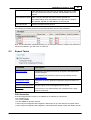
Options
The menu item ‘Options’ provides access to general (i.e. project independent) application settings. It
opens the ‘Options’ dialog, which lists the application settings in a ‘property grid’.
(c) 2012 MITSUBISHI ELECTRIC CORPORATION
Main Menu
4.3
Choices / Setting range
39
Name
Description
Default
GSD database has priority
when set to ‘True’, the user can replace exist- true, false
ing GSD data in the project file. Each time a
project file is opened, a list of the slave types,
which exist in both the project file and the
central GSD database, is displayed. The user
can select the slave types, of which the information should be replaced.
false
OK
Close dialog and save settings to become effective after next change
Default button
Cancel
Close dialog and discard changes
-
View Menu
In the View menu you can select the following menu commands:
Command
Description
Toolbar
Shows or hides the application’s toolbar.
Status Bar
Shows or hides the application’s status bar.
These menu commands toggle the display of the toolbar and the status bar. A check mark in front of
the command indicates that the corresponding bar is activated.
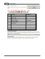
Command Toolbar
The toolbar is a collection of buttons, which provide direct access to the most frequently used functions. Its appearance depends on the type of the open project.
(c) 2012 MITSUBISHI ELECTRIC CORPORATION
40
GX Configurator-DP
Toolbar, if no project is open
Toolbar, if project is open and all functions are supported by
master
Icon
Function
Available for
1
Project -> New
all
2
Project -> Open
all
3
Project -> Save
all
4
GSD Device Database
master projects
5
Download to Module
all
6
Transfer Setup
all
7
POU Generation
master projects
8
Start/Stop PROFIBUS
all
9
I/O Mapper
master projects
10
Help
all
Command Status Bar
If this command is marked, the standard Windows status bar is displayed at the bottom of the application window. The status bar shows a short message of the menu item under the mouse cursor
and the status of certain keyboard keys.
Project Infobar
The infobar is a window of GX Configurator-DP, which is displayed above the standard Windows
status bar. It displays important information, which is specific to the active project.
(c) 2012 MITSUBISHI ELECTRIC CORPORATION
Main Menu
41
The following information is displayed in the infobar
1. the status of the PLC connection ('connected', 'not connected')
2. the name of the currently selected transfer setup
3. the type of the CPU selected in the transfer setup
4. the last path of the exported POU (only if 'POU Generation' has been called since the project has been opened)
4.4
Window Menu
The 'Window' pull-down menu lists the names of the open projects. Selecting an entry activates the
corresponding project window.
4.5
Help Menu
The 'Help' pull-down menu provides access to the online-help and version information of the application.
(c) 2012 MITSUBISHI ELECTRIC CORPORATION
42
GX Configurator-DP
Command
Purpose
Help Topics
Opens the online help
About
Displays version information of the application
Command Help Topics
This item opens the online help in a separate window. Additionally the context-specific help is
opened by pressing F1 in a window of the application.
Command 'About MELSOFT GX Configurator-DP ...'
The about box show the software name and version as well as the copyright notice.
(c) 2012 MITSUBISHI ELECTRIC CORPORATION
PROFIBUS Configurator Tasks
5
43
PROFIBUS Configurator Tasks
Using the Task Panel
The ‘PROFIBUS Configurator Tasks’ window offers the user project specific shortcuts to manage a
PROFIBUS DP project. The shortcuts are grouped into types of actions. With the button in the group
header the task items can be collapsed so that only the header is visible to the user.
‘collapsed’ task group
‘expanded’ task group
If operated via the keyboard the up/down cursor keys move the focus within the task panel. The focused task item is marked with a dotted frame.
Pressing the space bar triggers the focused item.
To expand/collapse a task group via the keyboard the caption of the task group must have the focus.
The expand/collapse state is then toggled via the spacebar.
(c) 2012 MITSUBISHI ELECTRIC CORPORATION
44
GX Configurator-DP
Some entries, which are frequently used, show icons before the text. These icons exist in the toolbar as well. Clicking the icon in the toolbar has the same effect as selecting the corresponding
entry in the task panel.
Tasks for Master Projects
The available items in the task panel depend on the project type and application state.
The task panel contains the following groups of items
· Online Tasks
(c) 2012 MITSUBISHI ELECTRIC CORPORATION
PROFIBUS Configurator Tasks
·
·
·
·
·
5.1
45
Setup Tasks
Export Tasks
Import Tasks
Documentation
Diagnostics
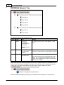
Online Tasks
Command
Description
Transfer Setup
Define the network connection type (PC to PLC)
In the integrated version of GX Configurator-DP this function is
available in the GX Work s2 application.
Download to Module
Download the configuration from the current project to the connected
module
In the integrated version this function is available from the GX
Work s2 'Write To PLC' dialog.
Upload Configuration
Image
Read the binary configuration image from the master and store it in
a file
In the integrated version this function is available from the GX
Work s2 'Tool' menu
Download Configuration
Image
Download the configuration image taken from the specified file to the
master module
In the integrated version this function is available from the GX
Work s2 'Tool' menu
Verify
Upload the existing configuration from the module and compare it
with the current project
In the integrated version this function is available from the GX
Work s2 'Verify with PLC' dialog.
Start/Stop PROFIBUS
Start or stop the cyclic DP data transfer
In the integrated version this function is available from the GX
Work s2 'Tool' menu
Set Slave Address
Change the FDL address of a slave online
(c) 2012 MITSUBISHI ELECTRIC CORPORATION
46
GX Configurator-DP
Command
Description
This function is only available for QJ71PB92V and FX3U64DP-M
In the integrated version this function is available from the GX
Work s2 'Tool' menu
Transfer Setup
This item opens the dialog for managing the communication settings of the PLC connections. For a
detailed description see Transfer Setup.
Connection Handling for Online Functions
If any of the functions listed in 'Online Tasks' is started, the settings of the currently selected transfer
setup are used to connect to the target PLC and the PROFIBUS module within the PLC.
If the connection to the target PLC fails for any of the 'Online Tasks', the user is informed with an error message.
The user can now choose to open the transfer setup to change the transfer settings and try again.
If the user selects ‘Yes’, the transfer setup dialog is opened.
If the connection to the PLC is established, GX Configurator-DP tries to locate the module at the
specified starting I/O number. If there is no module at the given starting I/O number or if the module
found does not match the current module type of the project, the user is informed and asked,
whether he wants to select the module online.
If the user presses 'OK', the list of modules is read from the PLC and displayed in a list.
(c) 2012 MITSUBISHI ELECTRIC CORPORATION
PROFIBUS Configurator Tasks
47
If the user selects a module matching the project type and presses OK, the respective online function is executed.
Download to Module…
When the user selects the ‘Download to Module’ task item or toolbar button, the user is asked to select the items for download.
Name
Items List
Description
Choices / Setting
range
Default
Download PROFIBUS configuration
selected / not selected
selected
Update Autorefresh settings
selected / not selected
selected
available only for Q-series projects, if
Autorefresh has been selected in 'CPU
Device Access'
(c) 2012 MITSUBISHI ELECTRIC CORPORATION
48
GX Configurator-DP
Name
Description
Choices / Setting
range
Default
Remove Autorefresh settings for the same
module type
selected / not selected
not selected
available only for Q-series projects
Select All
selects / deselects all items
selected / not selected / selected
indeterminate
OK
close dialog and start update of the selected
items.
Default button
Cancel
close dialog and do not download anything
-
(same as pressing OK with no item selected)
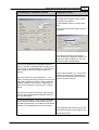
The selectable items, which are listed in the dialog, depend on the project type and settings.
1. Download PROFIBUS configuration
Download the PROFIBUS settings to the connected module.
2. Update Autorefresh settings
Add or update the autorefresh settings for the module with the configured head address.
3. Remove Autorefresh settings for the same module type
Delete existing autorefresh settings for the same module type. This option should be set, if for example a PROFIBUS module has been moved to a different slot or the I/O assignment has been
changed. When the CPU cannot find the specified module type at the specified head address, its
signals an error. GXDP only updates the autorefresh settings for the head address specified in the
'Master Settings'. Existing autorefresh settings for other head addresses remain unchanged.
The effects of this option depend on the state of the option 'Update Autorefresh settings'.
option 'Update Autorefresh settings' is selected: autorefresh settings for modules of the same
type as used in the project, but with different starting I/O numbers, are removed
option 'Update Autorefresh settings' is NOT selected or not available: all autorefresh settings
for modules of the same type as used in the project are removed, including settings for the starting I/
O number currently configured
If the user presses OK, the selected items are downloaded respectively updated. If the option 'Download PROFIBUS configuration' has been selected, the autorefresh settings are only updated, if the
previous configuration download has been successful. While the configuration image is written to the
module, a progress bar is displayed. This operation cannot be interrupted by the user to ensure a
consistent download.
A download to FX master modules can only be performed, if the CPU is in 'STOP' state.
If the download has been successful, the following message is displayed.
(c) 2012 MITSUBISHI ELECTRIC CORPORATION
PROFIBUS Configurator Tasks
49
For A(1S)J71PB92D modules the message contains an additional remark about the mode hardware
switch.
Note: for A(1S)J71PB92D modules the user must set the correct operation mode (0 or E) with the
switch on the front of the module. The module will take over the setting of the mode switch after a
CPU reset.
Download to project module type only
Note: a download is only possible, if the type of the connected module matches that of the project. If
the user wants to download the project to a different module type, the project must first be converted
to the type of the connected module. This is done by selecting the Change Master Type menu
item.
Autorefresh Update
If the user has selected the 'AutoRefresh' option, the autorefresh settings are updated, after the configuration has successfully been downloaded to the PROFIBUS master module. Before updating the
autorefresh settings GX Configurator-DP checks the total number of autorefresh entries, which the
CPU would have after the update. The total number of autorefresh entries per CPU is limited and this
limit depends on the CPU type.
If the maximum number of supported entries would be exceeded, the user is informed and the settings are not updated. In most cases this problem can be avoided by using 'Block Transfer' (see
'CPU Device Access').
The check is done when updating the CPU
as well as when updating the GD/GID-project, in case this has been assigned.
(c) 2012 MITSUBISHI ELECTRIC CORPORATION
50
GX Configurator-DP
The (online) update of the autorefresh settings on the CPU is only possible, if the CPU is stopped.
The CPU status is checked and, if the status is not 'STOP', the user is asked, whether the CPU can
be stopped.
After stopping the CPU the autorefresh settings on the CPU are updated. Existing autorefresh settings on the CPU for the same head address as the current master module are overwritten with the
settings for the master, existing settings for other modules remain unchanged.
If the CPU had been stopped prior to the update, the user is asked whether to start the CPU again.
The autorefresh settings in the parameter file of the corresponding GID/GD project are also automatically updated, if the path to an existing GID/GD project has been set (see 'Project Properties'). After
the GID/GD project has been updated, the path of the updated IParam file is displayed.
Autorefresh Settings on Remote I/O
GX Configurator-DP cannot online update the autorefresh settings in Q-series Remote I/Os. For Remote I/Os the settings must be updated in the corresponding GID/GD project file and then be up-
(c) 2012 MITSUBISHI ELECTRIC CORPORATION
PROFIBUS Configurator Tasks
51
dated in the Remote I/O itself with GID/GD. If the user downloads to a Remote I/O and no GID/GD
project path has been set, the user is prompted to enter the path to the IParam image file, which
should be updated.
In GID/GD projects the IParam image file is named 'iparam.wpa' and located in the subdirectory 'Resource' of the project directory.
Download to FX
The FX3U-64DP-M PROFIBUS master can only be updated, if the CPU is stopped. If the CPU is in
'RUN' state, the user is asked, whether the CPU can be stopped.
If the user agrees, the CPU is stopped and the configuration is downloaded. After the download has
completed, the CPU can be restarted.
(c) 2012 MITSUBISHI ELECTRIC CORPORATION
52
GX Configurator-DP
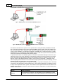
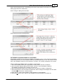
Download to QnPRH Redundant System
Type 1: QnPRH system w ith redundant PROFIBUS m asters
Type 2: QnPRH (2nd) system w ith single PROFIBUS m aster in expansion
backplane
The QnPRH redundant PLC system can be operated with a dual (redundant) PROFIBUS network.
The control CPU provides access to the active PROFIBUS master module, while the standby CPU
has a second master, which becomes active, when the standby system takes over the task of the
control system. Besides in a redundant configuration a QnPRH CPU can also be used as a single
standalone PLC or combined with another QnPRH PLC as a dual PLC system with both CPUs connected via a special communication link (‘tracking cable’).
To update both masters in a QnPRH system as well as the autorefresh settings in both CPUs, the
redundant system must be in ‘Separate’ mode and device tracking for the X/Y devices must be disabled. GX Configurator-DP therefore switches the redundant system to ‘Separate’ mode, if it is in
‘Backup’ mode. It also disables device tracking, if the system is in ‘Backup’ or ‘Separate’ mode.
After completing the download to both masters and having updated the autorefresh settings, GX Configurator-DP sets the system back into its original state.
The new QnPRH 2nd generation PLC supports a new type of expansion backplane, which is directly
connected to the backplanes of both QnPRH CPUs. The expansion backplane is mapped into the I/
O range of the respective control system. The modules in the expansion board are not visible to the
standby CPU. The QnPRH expansion board allows to operate a redundant PLC without having each
network module twice.
Mode
GXDP Handling
Backup
The PROFIBUS configuration is downloaded to both PROFIBUS modules
(redundant network setup) or the single PROFIBUS module (expansion rack
(c) 2012 MITSUBISHI ELECTRIC CORPORATION
PROFIBUS Configurator Tasks
Mode
53
GXDP Handling
setup). The autorefresh settings are updated in both PLCs. Therefore the
system must be temporarily switched to 'Separate' mode.
User must choose whether to update both systems (pressing ‘Yes’) or only
the directly connected system (as selected in transfer setup) (pressing
‘No’). If ‘Cancel’ is pressed, nothing is updated.
Separate
In Debug mode only the PLC selected in the transfer setup is updated.
Debug
Note: if device tracking is disabled, this applies only to the default tracking block controlled by
SM1520. If the user has specifically configured device tracking and included the X/Y devices of the
intelligent function modules, the communication may fail.
Verify
This function verifies the settings of the selected project with the current configuration of the module.
For PB92D masters a warning is displayed to inform the user that the data exchange on the
PROFIBUS network will be stopped.
The current configuration is read from the module and compared with the configuration created from
the current project. If both settings match, the following message box is displayed.
(c) 2012 MITSUBISHI ELECTRIC CORPORATION
54
GX Configurator-DP
If the settings differ, the following message box is displayed. More detailed information on which
parts of the settings are different, is not provided.
In case any problems occur, for example when reading the configuration from the module, a general
error message is shown.
Note: the autorefresh settings and POU code are not compared. Therefore device addresses used
for transfer buffer or assigned in the I/O mapper, which are not part of the master configuration, are
not verified. The verify may report a match, although device addresses differ.
Verify on QnPRH Redundant System
Before uploading the configuration from the PROFIBUS master module(s) and comparing it with the
project, the user is asked whether to proceed. The query depends on the redundancy mode, however
it does not depend on whether there are one or two master modules.
Mode
GX Configurator-DP Handling
If there are two masters, the configuration of both masters is uploaded and compared. If there is only one master, the configuration of that master is uploaded and
compared.
Backup
If there are two masters, the configuration of both masters can be uploaded and
compared. The user can also decide to verify only the configuration of the master in
the directly connected PLC rack. If there is only one master, the user's choice has
no effect.
Separate
(c) 2012 MITSUBISHI ELECTRIC CORPORATION
PROFIBUS Configurator Tasks
Mode
55
GX Configurator-DP Handling
In this mode only the configuration of the master in the connected PLC is verified.
Debug
If the configuration of two master modules in a redundant PLC system is verified, the result shows for
each of the two master modules, whether its configuration matches the current project or differs from
it.
If the configuration of both masters matches the project:
If the configuration of one or of both masters differs from the project:
If there is only one master module in the redundant system as in a QnPRH (2nd) with a single expansion backplane, only the configuration of this master is compared with the project.
(c) 2012 MITSUBISHI ELECTRIC CORPORATION
56
GX Configurator-DP
Upload Config. Image
The user is prompted for a file, in which the configuration image should be stored.
For PB92D masters a warning is displayed to inform the user that the data exchange on the
PROFIBUS network will be stopped.
The current configuration is read from the master module and stored in binary format in the file,
which the user has selected. Information stored in the PLC CPU like autorefresh settings or POU
code is not retrieved.
The user is informed after the successful upload
(c) 2012 MITSUBISHI ELECTRIC CORPORATION
PROFIBUS Configurator Tasks
57
or gets an error message, if it fails.
The configuration image can be used to configure another master module, if the original GXDP project file is not available. The configuration image is downloaded to a master with the 'Download
Config. Image' function.
Note: the information read from the master module cannot be used to create a GXDP project file.
Download Config. Image
The user must first select a file with a configuration image created by a previous upload (see 'Upload Config. Image') or the corresponding export function of GX Configurator-DP(see 'Export ->
Config. Image' ). This configuration must be compatible to the module type set in the current project. GX Configurator-DP reads the configuration image from the file and downloads it to the master
module.
The user is informed after the successful download
or gets an error message, if it fails.
Start/Stop PROFIBUS
This item is used to manually start or stop the PROFIBUS DP cyclic data transfer of DPV0. The current status of the connected PROFIBUS master is checked. If there is no active data transfer, GX
Configurator-DP checks, whether the master is configured and data transfer could be started. For A
(1S)J71PB92D, QJ71PB92D and QJ71PB92V the device X1B of the master must be true, for FX3U64DP-M address 5 in the buffer memory must be non-zero.
If the prerequisite condition is not met, the user is warned and data transfer cannot be started.
Otherwise the user is asked to confirm starting the transfer.
If the data transfer is active, the user is asked to confirm stopping the transfer.
(c) 2012 MITSUBISHI ELECTRIC CORPORATION
58
GX Configurator-DP
The cyclic data transfer is started respectively stopped. If a PLC program is running, which starts the
data transfer, while the user tries to stop the data transfer, the operation fails. An error message is
displayed and the user is informed of the possible access conflict between PC and PLC program.
Set Slave Address
This function is provided to change the FDL address of a slave device online.
Note: this function is only available for QJ71PB92V and FX3U-64DP-M and must be supported by
the slave.
The appearance of the dialog, which is opened when selecting the ‘Set Slave Address’ item, depends on the master type and the node, which is selected in the project tree.
for QJ71PB92V (Ident-No. must be entered)
Master is selected
for FX3U-64DP-M (Ident-No. not required)
(c) 2012 MITSUBISHI ELECTRIC CORPORATION
PROFIBUS Configurator Tasks
59
Slave is selected
If the master is selected, the user must enter the current address of the slave. For QJ71PB92V also
the ident number must be entered. If a slave is selected, the current slave address and the ident
number are taken from the project settings and both fields are read-only.
The service requires the current and the new FDL address as parameters, together with the ident
number of the slave, which is checked to ensure that the correct slave is accessed. The current address and the ident number are taken from the slave, which has been selected in the project tree.
By pressing ‘Set’ the request is sent to the slave. The response (success or failure) from the slave is
displayed in the ‘Messages’ field.
Request to change FDL address has been sent.
QJ71PB92V
Note:
A positive response does not imply that the slave has
actually changed its address. This must be verified by FX3U-64DP-M
the user with other means (e.g. using the 'Live List' function of FX3U-64DP-M).
Failure
Note that FDL address cannot be changed, if data transfer is active
Name
Description
Choices /
Setting
range
Old address
current FDL address of the slave
0 -126
(c) 2012 MITSUBISHI ELECTRIC CORPORATION
Default
60
GX Configurator-DP
Name
Description
Choices /
Setting
range
Default
If a slave is been selected in the project tree,
the address of that slave is set as default, if
the master is selected, the user can enter
any valid address
New address
the new FDL address to be set in the slave
0 – 125
Ident.-No. (hex)
the identification number is used to verify that
the correct slave is addressed.
the ident number (range
0x0000 –
0xFFFF)
This parameter is only required for
QJ71PB92V. If a slave has been selected in
the project tree, the ident no. of that slave is
inserted, if the master is selected, the user
must enter the correct ident number (for
QJ71PB92V only) in hex format.
The FX3U-64DP-M will internally determine
the ident number for the specified ‘old address’ and insert it into the PROFIBUS request.
5.2
Messages
the result of the operation (success or error
message)
Set
sends the ‘SetSlaveAddress’ request
Default button
Close
Close dialog
-
Setup Tasks
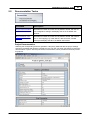
Command
Description
Master Settings
Open the 'Master Settings' wizard
Change Master Type
Convert the project to a different type of master module
Not available in the integrated version of GX Configurator-DP
GSD Device Database
Open the trees with the device types in the global device database
and in the project file
(c) 2012 MITSUBISHI ELECTRIC CORPORATION
PROFIBUS Configurator Tasks
61
Command
Description
Project Properties
Open a dialog to select the GID/GD project and to set the comment
Not available in the integrated version of GX Configurator-DP
I/O Mapper
Open the editor for defining the structures for access to slave inputs/
outputs
Devices for Slave-Specific
Transfer
Edit the device addresses for slave-specific data transfer
Note: this entry is only enabled, if 'slave specific' transfer has been
selected in ‘CPU Device Access’.
Change Master Type
With this menu item the user can change the current project to a different type of master module.
This menu item is not available in the integrated version of GX Configurator-DP.
Name
Description
Choices / Setting
range
CPU Series
selection of CPU series, in which the
PROFIBUS module is used
Qn, QnA/A, FX
MELSEC Module Type
module types supported by the selec- Qn:
ted CPU series
QJ71PB92V
Note: the current module type of the
QJ71PB92D
project is not listed
Default
Qn
QJ71PB92V
QnA/A:
A(1S)J71B92D
FX:
FX3U-64DP-M
OK
convert the project to the selected
type and close the dialog
Cancel
discard changes and close the dialog
Default button
If the type of the master is changed to a FX3U-64DP-M, the user is warned that device addresses,
which are not supported for FX3U-64DP-M projects, will be removed from the current project. This
warning is displayed independently of whether unsupported device addresses are actually used in
(c) 2012 MITSUBISHI ELECTRIC CORPORATION
62
GX Configurator-DP
the project or not.
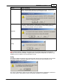
If the project can be converted, a message is displayed. If the change of the master type implies a
change of the CPU type, the user is also reminded to adjust the transfer settings.
The project conversion may fail, if the current configuration is not supported by the new master, for
example because of the number of slaves when converting a project from QJ71PB92V to
QJ71PB92D.
GSD Device Database
Opens the tree views for the device types stored in the global device database and in the project file.
For a detailed description see 'GSD Device Database'.
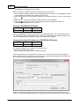
Project Properties
This dialog provides access to project specific properties
This menu item is not available in the integrated version of GX Configurator-DP.
Name
Description
Choices / Setting range
PLC Project
select the project file of the corresponding GD/GID project. The project directory is used to locate the image file for
autorefresh parameter settings
(iparam.wpa) in the ‘Resource’ subdirectory of the GD/GID project. This file is
Default
-
(c) 2012 MITSUBISHI ELECTRIC CORPORATION
PROFIBUS Configurator Tasks
Name
Description
Choices / Setting range
Default
63
updated by GXDP, if the ‘Autorefresh’option has been selected
Browse
opens file dialog to select the GD/GID
project file
max. 255 characters
-
Comment
an optional comment text of max. 255
characters length, which describes the
project
max. 255 characters
-
OK
Close dialog and save changes
Default button
Cancel
Close dialog and discard changes
-
I/O Mapper
Opens the table for defining 'Data Unit Types' (DUTs) and global variables for access to slave input
and output data. For a detailed description see 'I/O Mapping'.
Devices for Slave Specific Transfer
The item is only accessible, if slave specific transfer has been selected in ‘CPU Device Access’. It
opens a modal dialog, which lists the slaves configured in the project sorted by FDL address along
with their respective input and output size. The user can assign a device address to each input and
output area of slave. The contents of these devices are exchanged with the input and output areas in
the buffer memory of the master via autorefresh or copy instructions.
Name
Slave name
Description
Choices / Setting
range
user-assigned name of the slave
read-only
input and output size of the slave in
I/O Word Size words (odd byte sizes are rounded up
to the next word boundary)
(c) 2012 MITSUBISHI ELECTRIC CORPORATION
read-only
Default
64
GX Configurator-DP
Name
Description
Choices / Setting
range
Default
start address of device area to transfer
inputs to
for use with the I/O map- empty
per (POU) word devices
must be assigned; for use
with autorefresh the
devices must be supported by the autorefresh
function
Note: if a device address has been assigned to a buffer area, the occupied
device range is displayed with the adInput Device
dresses of the first and the last device
used. When the user begins editing a
cell, only the start address is disif the slave has no inputs
played. When the user has left the cell, or outputs, the corresthe updated range is displayed again.
ponding device address
input field is disabled
start address of device area to transfer
Output Device outputs from
Note: see above
OK
Close dialog and saves entered device
addresses
Default button
Cancel
Close dialog and discard changes
-
Slave Specific Transfer in Combination with 'Copy Instructions'
If 'Slave Specific Transfer' and 'Copy Instructions' is selected, the assignment of bit devices to slave
I/O buffers is equivalent to not assigning a device address.
The user is warned when entering a bit device for a slave buffer, if 'Copy Instructions' has been selected.
When pressing Cancel the entered address is ignored and the value for the buffer device remains
unchanged.
(c) 2012 MITSUBISHI ELECTRIC CORPORATION
PROFIBUS Configurator Tasks
65
When pressing OK the bit device address is accepted, but displayed in gray to inform the user that
the respective buffer will not be transferred.
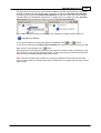
5.2.1
GSD Device Database
The device database contains information about PROFIBUS DP slave device types. New device
types are added to the database by parsing the GSD file of the device. When a slave is added to a
PROFIBUS master configuration project, the GSD information for the slave is copied from the global
GSD database to the project file. This enables the user to edit a project file on a different system,
without having to add the device types to the respective global database again. Due to these procedure there are actually two databases with GSD device information, the global database under the installation directory of GX Configurator-DP and the project file.
(c) 2012 MITSUBISHI ELECTRIC CORPORATION
66
GX Configurator-DP
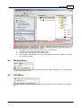
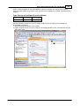
GSD Database Device Tree
A device database is accessed via a tree-like user interface. The GX Configurator-DP user interface
contains two device tree windows, one for the global GSD database, one for the GSD information in
the project file. You can switch between the two GSD data trees by selecting the corresponding tab.
Caption
Global GSD data
Tab
Caption
Project GSD data
Tab
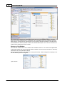
If a slave type from the 'Global GSD data' tree is added to the project and the GSD information for
that type is missing in the project, the GSD information is added to the project and a node for the
type is inserted in the 'Project GSD data' tree.
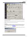
The device groups are represented by folders, with the device types of the group as child nodes. The
tree node of a device type shows the bitmap of the device and its type name. If no specific bitmap
has been assigned to the device, the default bitmap is displayed.
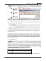
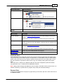
The device tree for the global GSD database provides a context menu with functions to modify the
database.
(c) 2012 MITSUBISHI ELECTRIC CORPORATION
PROFIBUS Configurator Tasks
67
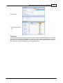
Slave selected in 'Global GSD data'
Group selected in 'Global GSD data'
Slave selected in 'Project GSD data'
Menu Item
Description
Add Slave to Project
add the selected slave to the project
Note: this menu item has the same effect as adding a slave via
drag&drop or a double-click on the node
Add GSD File
opens a file dialog to select a GSD file, which is to be parsed and added to the database
Import GSD Database
import device types from a GSD database (.mdb), GSD export file
(.ext) or GXDP project file (.dp2)
Properties
opens a dialog to view properties of the selected slave type.
In the 'Global GSD data' tree some of the properties can be changed,
e.g. the bitmap, in the 'Project GSD data' tree the properties are readonly
Remove Type
removes the slave from the database
Add Slave to Project
To add a slave of the selected type to the project, the user can either select the corresponding menu
item from the context menu of the GSD tree, double-click the node in the GSD tree or move the
mouse pointer to the project tree while keeping the left mouse button pressed.
(c) 2012 MITSUBISHI ELECTRIC CORPORATION
68
GX Configurator-DP
A slave can be added from the ‘Project GSD data’ and the ‘Global GSD data’ tree. If a slave type is
added from the ‘Global GSD’ tree and GSD information for the selected type is missing in the project
file, the GSD information is transferred from the global GSD database to the project file. If the slave
type is already in the project file, the information in the project file is not changed. When the project
is edited, the GSD information is always taken from the project to ensure data consistency.
Changes made to ‘Global GSD data’ will only have an effect on an existing project, if the GSD information is updated, when the project is opened. Please see 'Update GSD Information in Project'.
To make the user aware of the potential conflict of the same slave type existing in both GSD databases, a message box is displayed, if the user adds a slave from ‘Global GSD data’ to the project,
while GSD information of the same slave type already exists in the project.
By marking the ‘Do not show this message again’ checkbox, further display of this message is
avoided as long as GX Configurator-DP is running. When GX Configurator-DP is restarted, this mark
is cleared and the message is displayed again.
Add GSD File
A GSD file can be added to the database by selecting the item 'Add GSD File...' from the context
menu. A file dialog appears to select the GSD file. When leaving the dialog with OK, the GSD file is
parsed and its contents stored in the GSD database. The GSD file itself is no longer required. If the
GSD file references a bitmap file for the slave device, GX Configurator-DP automatically tries to load
the respective bitmap file and store it in the GSD database. In case the file is not found a default bitmap is used instead. The bitmap can be replaced with a device specific bitmap later on.
The PROFIBUS standard specifies the following format for the bitmap file:
Width
70 pixels
Height
40 pixels
(c) 2012 MITSUBISHI ELECTRIC CORPORATION
PROFIBUS Configurator Tasks
Colors
16
File Extension
dib, bmp
69
Only bitmaps that match the requirements in the table above should be used. Other bitmaps with
other sizes and color depths can be used, but may not be correctly displayed.
When the GSD file has been selected, you will be asked to confirm the operation.
If you confirm, the contents of the GSD file are parsed and added to the GSD database.
Please ask the manufacturer of the slave device for the matching GSD file.
(c) 2012 MITSUBISHI ELECTRIC CORPORATION
70
GX Configurator-DP
Import GSD Database
The GSD information for device types, which are missing in the GSD database, can be imported
from an old GSD database (gsd_db.mdb), a GSD export file (*.ext) or a GXDP project file (.dp2).
Note: it is strongly recommended to parse the GSD files for the slave devices using the 'Add GSD
File' function instead of importing the parsed GSD information from older databases. This ensures
that all GSD information supported by this version of GXDP is extracted from the GSD file.
Selecting the 'Import GSD Database' item in the context menu opens a file dialog to select the file
containing the GSD information to be imported.
If all device types found in the selected file already exist in the GSD database, the following message is displayed
If there are missing slave types, which can be imported, these types are displayed in a list.
Name
Description
Choices / Setting
range
Default
Slave Type
List
list of slave types, which exist in the
file selected for import, but not in the
GSD database
Select All
toggles the selection of the slave
types
OK
closes the dialog and adds the GSD
information of the selected slave
types to the GSD database
Default
button
Cancel
closes the dialog
-
(c) 2012 MITSUBISHI ELECTRIC CORPORATION
PROFIBUS Configurator Tasks
71
Device Type Properties
When the item 'Properties...' is selected in the context menu, the 'Device Type Properties' dialog is
displayed.
If opened in 'Project GSD data', the device settings cannot be changed and the corresponding controls in the dialog are disabled.
Name
Description
Choices / Setting range
Default
Vendor
company name of the vendor (usually the
value of the keyword ‘Vendor_Name’ in the
GSD file)
read-only
-
Revision
the version of the device respectively GSD
file (usually the value of the keyword ‘Revision’ in the GSD file)
read-only
-
Ident-No.
a number assigned by the PNO for unique
read-only
device type identification. The value is taken
from the entry ‘Ident_Number’ in the GSD
file.
-
GSD-/DDB-File
name of the GSD file
Bitmap
shows the slave-specific bitmap for the selected state, which has been stored in the
database.
Different bitmaps can be assigned to the fol-
(c) 2012 MITSUBISHI ELECTRIC CORPORATION
read-only
72
GX Configurator-DP
Name
Description
Choices / Setting range
Default
lowing states:
· Normal
· Diagnostics
· Special Function
GXDP only uses the ‘Normal’ bitmap for display.
Replace Bitmap
opens a file dialog for selecting the bitmap
file to be assigned to the selected state
in 'Global GSD
data': enabled
in 'Project GSD
data': disabled
Bitmap-File
name of the bitmap file
read-only
Slave Family
allows to alter the slave family set by the
in 'Global GSD
GSD file, under which the slave is located in data': enabled
the tree
in 'Project GSD
data': disabled
Set Byte Order
for User Parameter
selects the byte order for user parameters
of types short and long (signed and unsigned). This setting should normally never
be changed, because PROFIBUS specifies
big Endean, which is the default
Low byte first /
High byte first
High byte
first
in 'Global GSD
data': enabled
in 'Project GSD
data': disabled
OK
Close dialog and save changes
Default button
Cancel
Close dialog and discard changes
-
Replace Device Bitmap
The user can replace the existing bitmap of the slave by pressing the button 'Replace Bitmap'. This
opens a file dialog, in which a file with a new bitmap can be selected. The device database can store
three different bitmaps for a device type, used for different states of the device. Via the group of radio
buttons the state, in which the bitmap is used, is selected.
The GSD standard specifies bitmaps for:
· normal operation (this is used in the GX Configurator-DP editor)
· diagnostic status
· special operations mode
When a bitmap is replaced, this applies only to the selected state.
Change Slave Family / Group
When a slave device is added to the GSD database, it is placed in the slave family, which is specified in the GSD file. If no slave family has been specified, the slave is placed in the 'General' group.
The user can move the slave to a different group by selecting a group in the 'Slave Family' list and
pressing OK.
Change the Byte Order of User Parameters
The default setting for the byte order is ‘High byte first’ and should normally never be changed from
(c) 2012 MITSUBISHI ELECTRIC CORPORATION
PROFIBUS Configurator Tasks
73
its default setting, because incorrect user parameter settings may have unforeseeable effects on the
slave. To make the user aware of this a message box is displayed, whenever the user changes the
byte order in the dialog
If the user confirms, the byte order is changed, but will only effect new projects. Because existing
GXDP project files contain a copy of the GSD information, the change of the byte-order in the GSD
database has no effect on the existing project. The byte order of user parameters must not be confused with the byte-order of the slave I/O data.
Warning:
Please consult the vendor of the slave before changing the byte order as incorrectly encoded user parameters can have unforeseeable effects and may cause malfunctioning or
damage.
DPV1 Support
With DPV1 the meaning of the first three bytes of the slave user parameters is specified. Some
slaves, especially older models, have placed slave-specific parameters in this range of the user parameters. If a slave supports the standard DPV1 user parameter format, the GSD file should contain
an entry 'DPV1_Slave=1'. With some slaves this entry is missing in their GSD file, although the
slave require DPV1 support to be activated in the master. In these cases the entry 'DPV1_Slave=1'
must be inserted in the GSD file using a standard text editor (e.g. 'notepad'). After saving the modified file it must be added again to the GSD database.
GSD Update
If you try to add a GSD file to the device database for a device, which already exists, a warning is
shown. You can either choose to add the device information with a device revision or type name different to that of the existing device or choose to replace the existing entry.
Note: please be aware that GXDP uses the combination of
· ident number (GSD keyword 'Ident_Number')
· model name (GSD keyword 'Model_Name')
· revision (GSD keyword 'Revision')
to uniquely identify a device. Two GSD files must differ in at least one of these three items in order to
both be added to the GSD database.
(c) 2012 MITSUBISHI ELECTRIC CORPORATION
74
GX Configurator-DP
If you choose to replace the GSD file, internally the existing entry is deleted first and then the new
GSD file is parsed. This will however not effect existing projects, which already use the device type
and where the GSD information is part of the project file.
Removing Type
A device type can be removed from the database by selecting the 'Remove Type' item from the context menu. Before removing the device the user is asked to confirm the operation.
This deletes only the entry in the GSD database. It does not delete the GSD and bitmap files for that
device. These files have to be removed manually.
5.2.2
I/O Mapping
The purpose of I/O mapping is an easier access to the input and output data cyclically exchanged
between the PROFIBUS master and the connected slaves. In I/O mapping GX Configurator-DP generates PLC program code, which will
· transfer output data from buffer devices to the buffer memory of the master
· transfer input data from the buffer memory of the master to the buffer devices
· generate ‘Data Unit Types’ (DUTs) for each slave module
· exchange data with devices selected by the user
· start the cyclic data exchange
· copy contents of diagnostic buffers to assigned devices
· reference I/O data via global variables
Instead of calculating the I/O data offsets of the slave modules within the I/O buffer of the master, the
PLC program can read or write the respective global variables. These are part of the user library,
which is generated via the menu item POU Generation.
I/O mapping program code is only available for the following master modules and operating modes
· A(1S)J71PB92D (only for mode E and QnA-CPUs !)
· QJ71PB92D (only for mode E !)
· QJ71PB92V
· FX3U-64DP-M
Note: there is no I/O mapping and POU support for A-series CPUs and for A(1S)J71PB92D and
QJ71PB92D in mode 0.
I/O Mapping Editor
To open the editor for I/O Mapping select the corresponding item in the task panel.
(c) 2012 MITSUBISHI ELECTRIC CORPORATION
PROFIBUS Configurator Tasks
75
The navigation in the I/O mapping editor is done via the 'PROFIBUS Network' tree. The contents of
the I/O mapping table depend on the node type, which is selected in the project tree.
Selected Node Type
I/O Mapper Table Contents
Master
-
Slave
only the DUTs for the modules of the selected slave
Slave Module
only the DUT of the selected module
If a slave is selected, the DUTs of all modules of that slave are displayed in ‘collapsed’ state as default. The user can expand a DUT to view the DUT elements by pressing the ‘expand’ button in the
‘Identifier’ column.
(c) 2012 MITSUBISHI ELECTRIC CORPORATION
76
GX Configurator-DP
If a module is selected, the DUT of the module is displayed in ‘expanded’ state as default. The
user can collapse a DUT by pressing the ‘collapse’ button in the ‘Identifier’ column.
I/O Mapping Table
The I/O mapper table contains two types of rows
(1) a row for each DUT global variable showing the editable variable name
(c) 2012 MITSUBISHI ELECTRIC CORPORATION
PROFIBUS Configurator Tasks
Column
Range
Description
Identifier
1-32 chars name of global variable
77
Default
(2) a row for each element of a DUT
Column
Range
Description
Default
Identifier
1-32 chars
name of DUT element
‘inputs’ or ‘outputs’ depending on buffer
Element Type
ARRAY,
BOOL, INT,
WORD
data type
BOOL, ARRAY OF BOOL,
WORD or ARRAY OF
WORD depending on buffer
Class
Input or Output
‘Input’ (data from PROFIBUS
slave to PLC CPU)
depending on buffer
or ‘Output’ (data from PLC CPU
to PROFIBUS slave)
User MIT-Address
Global Var.
Identifier
0-32 chars
optional fixed device address,
which contains a copy of the corresponding I/O point
empty
optional fixed global variable,
which contains a copy of the corresponding I/O point
empty
Note: the type name of a DUT cannot be set by the user, but is always automatically constructed,
when the PLC code is exported. To ensure that the type name is unique the starting I/O number of
the master, the FDL address of the slave and the index of the module are composed in the type
name: tHA<starting I/O no.>SLV<FDL address>MOD<module index (slot)>
Warning:
The buffer devices should not be directly accessed. If a 'Copy POU' with DUTs is used, the
contents of the DUT variables, which are generated for all modules, are copied to the buffer
devices. Data, which has directly been written by the application to these devices, is overwritten.
Note: the 'Global Variable List' (GVL) in GX IEC Developer (GID) will report overlapping addresses,
because the addresses in the transfer buffer are referenced by
1. the automatically generated variables for the I/O transfer buffer
2. the global variables for DUTs
3. the global variables, which the user assigned to individual DUT elements
These warnings can be ignored.
DUT Variable Name
DUTs have no global variable names assigned as default. The cell for the DUT variable name contains the prompt ‘<Enter Var. Name>’. The user can select the cell and enter a unique variable
name. The variable name may not be a PLC device address.
(c) 2012 MITSUBISHI ELECTRIC CORPORATION
78
GX Configurator-DP
DUTs are exported and instantiated, if…
1.
the user has selected the PLC code option ‘All DUTs’
2.
the user has selected the PLC code option 'User variables' and
...has assigned a variable name to the DUT
...has assigned a device as ‘User MIT-Address’ (see ‘User MIT-Address’)
...has assigned a global variable name in ‘Global Var. Identifier’ (see ‘Global Var. Identifier’)
In these three situations a default name for the DUT global variable is constructed with the following
scheme:
‘vHA<starting I/O no.>SLV<FDL address>MOD<module index (slot)>’
For example with
1.
PROFIBUS master in the first slot (starting I/O number 0x00)
2.
slave with FDL address 2
the DUT of the first module (index 0 in the slave) has the variable name ‘vHA0SLV2MOD0.
Program code with declaration of DUT variable with entered variable name:
…
VAR_GLOBAL
binaryInputs: tHA4SLV10MOD01;
END_VAR
PROGRAM MAIN_PRG_LD
(**)
…
The tooltip of the ‘DUT Variable Name’ cell shows the type name of the module, which is represented by the DUT.
DUT Element Identifier
The default DUT elements are either taken from the configuration file, which contains the predefined
DUTs for ST1H-PB slave modules, or constructed from the buffer class, i.e. ‘input’ or ‘output’. The
user can change the identifier by clicking in the corresponding cell and editing the name. The identifier must be unique within the DUT.
Note: the DUT elements of predefined DUTs (e.g. for ST1H-PB) cannot be changed. For these DUTs
the element identifier, type and class are read-only.
Program code with declaration of DUT with entered element identifier:
TYPE
(c) 2012 MITSUBISHI ELECTRIC CORPORATION
PROFIBUS Configurator Tasks
79
tHA4SLV10MOD01:
STRUCT
bitSignals: ARRAY [0..7] OF BOOL:=[8(FALSE)];
END_STRUCT;
END_TYPE
…
When the DUT is validated and multiple element identifiers are detected, an error message with a list
of identifiers is displayed.
Type of DUT Element
For each slave module, which is added to the PROFIBUS configuration, GX Configurator-DP gener-
(c) 2012 MITSUBISHI ELECTRIC CORPORATION
80
GX Configurator-DP
ates a default DUT structure. It consists of an element for the module inputs and one for the module
outputs. The default elements have the type ‘ARRAY OF BOOL’ with the size of module’s input respectively output area, if the I/O-size of the module is an odd number of bytes. If the I/O-size is an
even number of bytes, the default type is WORD or ARRAY OF WORD.
The user can change the data type of a DUT element by selecting the corresponding cell in the
column ‘Element Type’ and either click into the cell or press <F2>. A button appears in that cell,
which opens the ‘Type Selection’ dialog(s), offering the following data types
Data Type
Size in I/O Buffer
BOOL
1 bit
INT
16 bit (signed)
WORD
16 bit (unsigned)
ARRAY OF
<Type>
number of array elements multiplied with size of data type
Instead of clicking into the button in the cell, you can press <F4> to open the 'Type Selection' dialog.
If the user selects the type ‘ARRAY’ in the first dialog, a second dialog is displayed to select the
data type of the array elements. After the type selection dialog has been closed by pressing the OK
button, the type text in the cell is updated. This text can be manually edited, e.g. to adjust the array
size.
Note: the start index is always 0. If any other index has been entered, it is automatically changed
back to 0 and the last index is set to the array size minus 1.
Program code with declaration of DUT with entered element type:
TYPE
tHA4SLV10MOD01:
STRUCT
bitSignals: ARRAY [0..7] OF BOOL:=[8(FALSE)];
END_STRUCT;
END_TYPE
…
When the DUT is validated, the total size of all input and of all output elements is compared with the
input/output size of the module. If the DUT size exceeds the size of the module, an error message is
displayed.
(c) 2012 MITSUBISHI ELECTRIC CORPORATION
PROFIBUS Configurator Tasks
81
DUT elements, which are not of BOOL or ARRAY OF BOOL type, are automatically byte aligned. If
for example a BOOL input element is followed by a WORD input element, the WORD element will
be byte-aligned by inserting seven padding bits between the BOOL and the WORD element. The
padding bits do not show up in the type definition, but are accounted for when assigning the device
addresses in the global variable declaration.
TYPE
tHA4SLV10MOD01:
STRUCT
bitSignal: BOOL:=FALSE;
wordData: WORD:=0;
END_STRUCT;
END_TYPE
…
This results in a total I/O size of 24 bits (i.e. three bytes), instead of the 17 bits occupied by the
defined DUT elements.
Note: WORD and INT variables can only reference device addresses, which are word-aligned. If a
WORD/INT element in a DUT refers to a position in the transfer buffer, which is not on a word boundary, the corresponding DUT element must therefore be copied. This results in additional program instructions and increased memory use. For more efficient code the user should therefore pay attention to the sequence of PROFIBUS slave modules within a slave and of the type and order of DUT
elements for each slave module.
Class of DUT Element
The class of a DUT element specifies the direction of the data transfer
Class
Direction of Data Transfer
Input
data from PROFIBUS slave to PLC CPU
Output
data from PLC CPU to PROFIBUS slave
If the corresponding module has only inputs or outputs, the ‘Class’ property is fixed.If the module
(c) 2012 MITSUBISHI ELECTRIC CORPORATION
82
GX Configurator-DP
has both inputs and outputs, the user selects with the class property, whether the respective DUT
element is located in the input or output area of the module.
To see the selection list click into the cell and click onto the button, which appears, or press <F2>
to open the selection list.
User MIT-Address
The user can assign an optional fixed device address to a DUT element. This device address will
contain a copy of the respective DUT element. This feature benefits users, which always use the
same device address for a certain function and do not want to use the symbolic access via a global
variable name.
If the user clicks in the cell for the ‘User MIT-Address’ or presses <F2>, a button appears in the cell.
Pressing the <F4> button opens a list of supported device types and address ranges. When a
device type in this list is selected, the selected device type with address 0 is copied to the cell.
For example if the entry ‘M[0-8191]’ has been selected in the list, the device ‘M0’ is copied to the
cell. This default device address must then be edited by the user.
For BOOL elements the device must be a bit type or a word type with bit index.
If the user specifies a global variable name together with the device address, the global variable is
placed at the specified device address. Only a single 'LD/ST' pair is used to transfer data from/to the
user device and global variable element (except for ARRAY OF BOOL elements).
If the user does not specify a global variable name, but just a user device address, a temporary variable name is generated. This allows to create the same structure of POU code independently of
whether a variable name has been specified or not.
(c) 2012 MITSUBISHI ELECTRIC CORPORATION
PROFIBUS Configurator Tasks
83
Global Var. Identifier
The user can assign an optional additional global variable (GV) identifier to each DUT element. This
adds the definition of a variable with the same type as the corresponding DUT element and the name
entered by the user. This global variable contains a copy of the data of the corresponding DUT element. The identifier must be unique and may not be a device address.
The user defined global variable allows to use a simple fixed variable name instead of accessing the
data via the DUT global variable. For the example in the previous figure the data can be accessed
1.
via the simple global variable ‘myvariable’ or
2.
via the DUT element ‘ModuleReady’ of the DUT GV ‘myDUTvariable’, i.e. ‘myDUTvariable.ModuleReady’
Program code with
1.
declaration of DUT
2.
declaration of DUT variable with device addresses for DUT elements
3.
declaration of user variable mapped to same device address as corresponding DUT element
TYPE
tHA4SLV12MOD2:
STRUCT
ModuleReady: BOOL:=FALSE;
ForcedOutputMode: BOOL:=FALSE;
END_STRUCT;
END_TYPE
VAR_GLOBAL
myDUTvariable AT @'%MX0.100.8,%MX0.200.4': tHA4SLV12MOD2;
END_VAR
CONFIGURATION scConfiguration
RESOURCE scResource ON scResourceType
VAR_GLOBAL
myvariable AT %MX0.100.8: BOOL:=FALSE;
END_VAR
END_RESOURCE
END_CONFIGURATION
When the DUT is validated and global variable names are used several times, an error message with
a list of global variable names is displayed (please notice that global variable identifiers are casesensitive).
(c) 2012 MITSUBISHI ELECTRIC CORPORATION
84
GX Configurator-DP
Note: the I/O mapping editor checks only the global variable names in the editor. A check of all variable names used in the project is done, when the POU is exported (see 'Check of Global Variable
Identifiers').
Insert/Remove DUT Elements
Functions for changing the structure of the DUT are called via a context menu. The context menu differs depending on the type of row, which is selected in the table.
The context menu, if the DUT variable row is selected
The context menu, if a DUT element row is selected
The user can change the structure of a DUT by adding or removing elements. The context menu in
the DUT table contains the items
Menu Item
Function
Insert Element before
adds a new DUT element above the currently selected one
(c) 2012 MITSUBISHI ELECTRIC CORPORATION
PROFIBUS Configurator Tasks
85
If the new element is not the first one, its default settings are copied
from the previous DUT element, identifier and MIT-address are incremented.
Insert Element behind
adds a new DUT element below the currently selected one
The default settings of the new element are copied from the previous
DUT element, identifier and MIT-address are incremented.
Remove Element
removes the selected DUT element
The following screenshot shows the incremented identifiers and user MIT-addresses.
Note: the DUT elements of predefined DUTs (e.g. for ST1H-PB) cannot be changed. For these DUTs
the element identifier, type and class are read-only.
5.3
Export Tasks
Command
Description
POU Generation
Generates import file and user library for import in GX Works2 and
GX IEC Developer
For availability and restrictions please see the following section
'POU Generation'.
Configuration Image
Generates the binary download configuration image and writes it to
a file
Project in GX ConfiguratorDP Format
Exports project file in GX Configurator-DP file format.
This function is only available when GX Configurator-DP is integrated in GX Works2.
POU Generation
This GX Configurator-DP function is not available in the following circumstances:
· for A-series CPUs
· for A(1S)J71PB92D
· for QJ71PB92D in operation mode '0'
· when using GX Configurator-DP integrated in GX Works2 in any other than the European version
· when using GX Configurator-DP integrated in the GX Works2 European version with GXW2 'simple'
(c) 2012 MITSUBISHI ELECTRIC CORPORATION
86
GX Configurator-DP
projects except for Q-series Remote I/O
Note: any changes in the master configuration, which change the I/O structure (i.e add/remove
slaves or modules), require to generate the I/O Mapping-POU again and to repeat the import.
This function generates PLC program code for GX Works2 (GXW2) and GX IEC Developer (GID),
which assists the application programmer in accessing slave input and output.
GX Configurator-DP generates an ASCII file (.asc) and a user library (.sul). The ASCII file contains
the task definition and the reference to the user library. The user library contains the DUT definitions,
global variable declarations and program instructions for I/O mapping. The ASCII file must be imported in GX IEC Developer. The user library referenced therein is automatically imported as well. Because the ASCII file contains the absolute path of the user library, the user library must not be
moved to a different directory.
The user can select the directory and the name of the POU ASCII file. The file name must start with
a letter and not have more than 24 characters. The file name is also used as name for user library
and program.
The user library is located in the same directory, but with the extension '.sul' instead of '.asc'.
Note: if the PROFIBUS master is located in a Q-series 'Remote I/O' rack, the POU must be imported in the GID project for the controlling PLC, not the project of the 'Remote I/O' rack.
If in a A(1S)J71PB92D project the selected transfer setup references an A-series connection, no
POU is exported. A message is displayed instead to inform the user that POUs for A(1S)J71PB92D
projects can only be created for QnA CPUs.
(c) 2012 MITSUBISHI ELECTRIC CORPORATION
PROFIBUS Configurator Tasks
87
Check of Buffer Device Addresses
The POU does only support word devices for transfer buffers. If a bit device has been assigned to the
input or output transfer buffer or even no device address has been assigned to inputs and/or outputs,
the user is informed that the inputs and/or outputs will not be included in the POU code.
If 'Block Transfer' is selected:
If 'Slave Specific Transfer' is selected:
Check of Global Variable Identifiers
Global variable identifiers must be unique. This restriction is checked for all global variable names
used within the PROFIBUS master user library.
Global variable identifiers are not case-sensitive. Therefore the use of 'gvname' with different forms of
capitalization results in following error messages
The variable names must be changed in the I/O Mapper, before POU and user library can be exported.
Note: because only the current master configuration can be checked, variable identifiers may conflict with the variable identifiers used in other master configurations, if multiple master modules are
used within the same PLC rack.
Check Overlapping Device Addresses
Device addresses, which have been assigned to DUT elements (see 'User MIT-Address') or to buffer
(c) 2012 MITSUBISHI ELECTRIC CORPORATION
88
GX Configurator-DP
areas (see 'CPU Device Access'), are checked for conflicts.
If device areas overlap, the conflicting nodes and device addresses are listed.
The user can either ignore the conflicts and proceed by pressing OK or press Cancel and open the
corresponding input dialog to change the device addresses.
Configuration Image
With this menu command the user is prompted for a file path to store the configuration image, which
is generated from the current project. The configuration image contains the binary encoded structure
of master and slave parameters as they are stored in the master. Its contents are therefore specific
for the type of the master.
Project in GX Configurator-DP Format
This task item is anly available in the integrated version of GX Configurator-DP.
The user is prompted for a file path to store the current project into.
(c) 2012 MITSUBISHI ELECTRIC CORPORATION
PROFIBUS Configurator Tasks
5.4
89
Import Tasks
Command
Description
Import GX Configurator-DP
Project
Imports GX Configurator-DP project file (*.dp2, *.dpx). The behaviour
is similar to the 'Open Project' menu item.
Only available in the integrated version of GX Configurator-DP
Add GSD File
adds the contents of a GSD file to the device database
Import GSD Database
import device types from a GSD database or a project file
Import GX Configurator-DP Project
This task item is only available in the integrated version of GX Configurator-DP.
(c) 2012 MITSUBISHI ELECTRIC CORPORATION
90
GX Configurator-DP
The starting I/O address stored in the GX Configurator-DP project will be ignored during import, and
the starting I/O address of the module already set will be kept.
In case of master modules, importing a project created for another type of Q-series master will be
possible with the following conditions:
· Settings which exist for both the source and the target module type will be imported without
change.
· Settings which exist for the source module type but not for the target module type will not be imported.
· Settings which exist for the target module type but not for the source module type will be set to
default.
· If the settings cannot be imported due to a hardware limitation, an error message will be displayed
and the project will not be imported. For example, QJ71PB92D modules can have maximum 60
slaves, but in a QJ71PB92V project there may be more than 60, because QJ71PB92V modules
support 125 slaves. In that case import will fail with this error message:
In case of master modules the following message will be displayed if the opened project has a different Q-series master module type than the current module:
(c) 2012 MITSUBISHI ELECTRIC CORPORATION
PROFIBUS Configurator Tasks
1
91
Name
Description
Choices / Setting range
Default
-
Actual module type of project
QJ71PB92D,
QJ71PB92V
-
In addition, if a QJ71PB92D Mode 0 project is selected to be imported to a master module, the following message will be displayed:
In case a Q slave QJ71PB93D project is attempted to be import to the configuration of a master
module, the following message will be displayed:
In case a Q-series master module project is attempted to be imported to a QJ71PB93D configuration, the following message will be displayed:
(c) 2012 MITSUBISHI ELECTRIC CORPORATION
92
GX Configurator-DP
1
Name
Description
Choices / Setting range
Default
-
Actual module type of project
QJ71PB92D,
QJ71PB92V
-
In case an unsupported module’s project is attempted to be imported, the following message will be
displayed:
1
Name
Description
Choices / Setting range
Default
-
Actual module type of project
-
-
If the Import has been completed succesfully, the following message is displayed:
(c) 2012 MITSUBISHI ELECTRIC CORPORATION
PROFIBUS Configurator Tasks
5.5
93
Documentation Tasks
Command
Description
Project Documentation
Generates an HTML file, which can be printed or stored, with the current configuration settings and displays the file in the default web
browser
Documentation of I/OMapping
Generates an HTML file, which can be printed or stored, with information on I/O mapping (e.g. buffer devices, data structures, variable
names) and displays the file in the default web browser
Project Documentation
Selecting the corresponding task item generates a temporary HTML file with the project settings
and opens the default web browser to display the file. The user can either save the file for electronic
documentation or print it with the print function of the browser, which provides all necessary formatting options.
(c) 2012 MITSUBISHI ELECTRIC CORPORATION
94
GX Configurator-DP
Note: the project documentation lists the selected modules of each slave. The 'slot index' is the sequential index of the module. It is not necessarily identical with its physical slot, as it is displayed
for example by the configuration tool of the slave. At the end of the project document a note describes the slot index.
Documentation of I/O-Mapping
The I/O mapping information can be exported into a separate HTML document. This document lists
the global variables for the DP slave modules. It also contains the definition of all exported DUT variables along with the buffer device addresses of each DUT element.
The device addresses are entered in MIT format in the GX Configurator-DP dialogs, but exported with
the POU in IEC format. Therefore both formats are displayed in the columns for user and buffer MIT
address. The IEC address is displayed in brackets next to the corresponding MIT address.
If global variable names or user device addresses have been assigned to individual DUT elements,
these variable names and device addresses are listed as well.
The HTML document is displayed in the default web browser. Using the print menu of the web
browser the document can be printed. The file can also be saved to a different path for electronic
documentation.
Links constructed from the DUT variable names allow the user to navigate within the document
between the PROFIBUS network structure and the definition of the corresponding DUT variable.
(c) 2012 MITSUBISHI ELECTRIC CORPORATION
PROFIBUS Configurator Tasks
95
The I/O mapping documentation is also very useful for users of GX Developer (GD). Because GX
Configurator-DP only generates code for GX IEC Developer (GID), GD users cannot import the PLC
code exported from GXDP. They can however lookup the device addresses of PROFIBUS I/O points
in the documentation and manually add them to their GD program.
Note: bit devices, which have been assigned to the transfer buffers, are not supported by I/O mapping. They are equivalent to having no device address assigned. Therefore the 'Buffer MIT Address'
column remains empty for bit devices.
5.6
Diagnostics Tasks
The available diagnostic functions depend on the type of master module selected in the current project.
Note: In the integrated version of GX Configurator-DP the diagnostic function are accessible via the
'Tool' menu of the GX Works2 application.
(c) 2012 MITSUBISHI ELECTRIC CORPORATION
96
GX Configurator-DP
not available in the integrated version of GX Configurator-DP
A(1S)J71PB92D
available from the 'Tool'
menu in the integrated
version of GX Configurator-DP
QJ71PB92D
available from the 'Tool'
menu in the integrated
version of GX Configurator-DP
QJ71PB92V
not available in the integrated version of GX Configurator-DP
FX3U-64DP-M
Diagnostic functions, which access the configuration of the master, can only be executed, if cyclic
data transfer has been started. Extended information like slave-specific error messages require additionally that the PROFIBUS configuration of the master matches the active project. Both conditions
are checked, when one of the functions ‘Slave Status’, ‘Diagnosis Messages’ or ‘Slave I/O Test’ is
started.
If the cyclic data transfer is stopped, an error message is displayed.
If the I/O structure of the master (i.e. number of slaves, their FDL addresses and I/O sizes) differs
from the project:
(c) 2012 MITSUBISHI ELECTRIC CORPORATION
PROFIBUS Configurator Tasks
97
Turn on/off Monitor Mode
While in monitoring mode, the current PROFIBUS configuration cannot be modified.
Selecting the item 'Turn off Monitor Mode' stops the monitoring and changes the application to ‘edit’
mode. The icon and the text of the task item change together with the change from ‘Monitor’ to ‘Editor’ mode.
If diagnostic views with monitoring function (‘Slave Status’, ‘Diagnostic Messages’) are open, selecting ‘Turn on Monitor Mode’ activates the monitoring in these views. The monitoring in the ‘Slave I/O
Test’ view must be started manually within the view.
If the item ‘Turn on Monitor Mode’ is selected, while no view is open, for which monitoring can be activated, the following message is displayed.
Slave Status
(c) 2012 MITSUBISHI ELECTRIC CORPORATION
98
GX Configurator-DP
The purpose of the ‘Slave Status Matrix’ is to provide a fast overview of the communication situation
within the PROFIBUS network. A two-dimensional matrix of rectangles shows all possible device
addresses within a PROFIBUS network. The state of a slave with a certain FDL address is signaled
by the color of the corresponding rectangle:
Color
Meaning
light grey
no device with this address included in the configuration
dark grey
slave has not been selected as ‘Active’ in the slave settings dialog
(restriction for A(1S)J71PB92D and QJ71PB92D see note below)
yellow
slave has sent diagnostic information
green
slave is included in the cyclic data transfer (has a link)
(restriction for A(1S)J71PB92D and QJ71PB92D see note below)
red
communication with slave failed, i.e. no link (the master may have generated a
diagnostic message stating the exact reason. This message is added to the
‘Diagnostic Messages’ table)
(restriction for A(1S)J71PB92D and QJ71PB92D see note below)
Additionally to the color display the user can double-click a rectangle and see in a tooltip-window a
more detailed description of the device state.
Below the grid with the slave states the view shows the current actual bus cycle time, which is continuously measured by the master. Additionally the minimum and the maximum of the bus cycle
time, since the data transfer has been started, are displayed (values only provided by QJ71PB92V
(c) 2012 MITSUBISHI ELECTRIC CORPORATION
PROFIBUS Configurator Tasks
99
and FX3U-64DP-M).
Note: the older PROFIBUS master modules AJ71PB92D and QJ71PB92D do not provide the states
‘active/ inactive’ and ‘link/no link’ online. This information is obtained by:
1. active/inactive: the ‘active’state of the slave in the current project, which has the same FDL address, is displayed, if the I/O structure of the master matches the one of the active project
2. link /no link : if the slave is active and the ‘has diag. messages’ flag is not set, the slave state is
‘link’ (i.e. green). The state ‘no link’ (i.e. red) is never displayed.
Diagnosis Messages
This view lists messages for PROFIBUS events as well as diagnostic information coming from slave
devices. Slave specific error codes are translated to test messages using the entries of the GSD file
of the slave type. The number of messages is limited to 1000. If more messages are received, the
oldest messages are removed from the list.
Column
Description
Entry time
time, when the message was received in the PC
Note: the master does not provide a time mark with the message
Slave name
name assigned by the user
FDL address
station address of the device
Status
icon (information, exclamation, stop)
Note: at present the table only contains diagnostic messages, which have either
been generated by the master or have been sent by a slave. These entries are all
marked with the ‘exclamation’
Message
diagnostic text (either standardized message or slave specific text from GSD file)
(c) 2012 MITSUBISHI ELECTRIC CORPORATION
100
GX Configurator-DP
A popup menu can be opened from the caption, which provides the functions
Menu Item
Description
Start
starts the continuous update of the message window
Stop
stops the update
Clear
deletes all messages from the window
Export
exports the messages to a CSV file selected by the user
The same popup menu is also opened as context menu, when the right-mouse button or the ‘context-menu’-key on the keyboard are clicked.
The current communication status is indicated by an icon in the caption
Online
Offline
Note: the master modules AJ71PB92D and QJ71PB92D have a limited storage capacity for diagnostic messages. They can only store eight standard messages and extended diagnostic information only for one event. This can result in diagnostic messages not being stored and thus not displayed.
Slave I/O Test
(c) 2012 MITSUBISHI ELECTRIC CORPORATION
PROFIBUS Configurator Tasks
101
Selecting the item ‘Slave I/O Test’ in the ‘Diagnostics’ task group opens a view, which provides read/
write access to the slave input/output areas in the buffer memory of the PROFIBUS master.
Control /
Command
Description
Range
Default
Slave
select slave from list of slave
nodes in project
slaves in project
slave selected in
project tree or first
slave
Value format
format of item in ‘Value’ column
see list below
16 Bit (decimal)
Byte order
byte order for numerical value
formats
Little Endean (Intel)
Little Endean
Start/Stop
Monitor
starts respectively stops the cyclic update of the table with the buffer contents read from the
PROFIBUS module
‘Start Monitor’, if mon- ‘Start Monitor’
itoring is stopped;
‘Stop Monitor’, when
monitoring is active
Write
write the buffer contents to the
PROFIBUS module
disabled while in monitoring; otherwise enabled
Buffer table
buffer contents displayed as bits
and in the selected value format
Big Endean (Motorola)
see detailed description below
Value formats
WORD (16 Bit hex.)
one word as unsigned hexadecimal number
DWORD (32 Bit hex.)
two words as unsigned hexadecimal number
INT (16 Bit decimal)
one word as signed decimal number
DINT (32 Bit decimal)
two words as signed decimal number
Byte order
(c) 2012 MITSUBISHI ELECTRIC CORPORATION
102
GX Configurator-DP
Low byte first
low byte on lower address, e.g.
(little Endean / Intel)
a WORD value 0x1234 is the byte sequence 0x34, 0x12
a DWORD value 0x12345678 is the byte sequence 0x78, 0x56, 0x34, 0x12
High byte first
high byte on lower address, e.g.
(big Endean / Motorola)
a WORD value 0x1234 is the byte sequence 0x12, 0x34
a DWORD value 0x12345678 is the byte sequence 0x12, 0x34, 0x56, 0x78
Buffer table
Description
Column
Address
word address in user area of buffer memory
.F - .0
value of bit with the respective index in hex
The bit can be edited by a double-click in the cell.
To help the user in identifying the buffer address, a tooltip shows for each bit cell
the buffer address and bit index.
Value
value of buffer contents displayed in the selected value format
If the value size is two words, the value is only displayed in the row of the first
word; the ‘Value’ column for the second word remains empty.
The value can be edited by a double-click in the cell.
(c) 2012 MITSUBISHI ELECTRIC CORPORATION
PROFIBUS Configurator Tasks
103
Highlighting of changes
Mode
Description
Display
If a value changes during monitoring compared with
the value read in the first update, it is displayed in
red bold digits and letters.
Monitoring
When monitoring is stopped, the highlighting remains, until monitoring is restarted or the user begins to edit the buffer. In both cases (monitoring
and editing) the display begins with no highlighting.
If there is a communication break during monitoring
between PC and PLC, the background of the table
is colored in light red to indicate to the user that
the values are not updated. While monitoring is
active, GX Configurator-DP checks the connection
and reconnects, if the PLC is online. The background then changes back to the standard color.
If a value is changed during editing, the value is
displayed in black bold digits and letters.
Editing
If the values have been successfully written to the
PROFIBUS module, all highlighting is cleared.
Note: the user must be aware that slave inputs are overwritten in buffer memory, if the PROFIBUS
(i.e. the cyclic data transfer) has been started. So the table may not display the actual buffer contents. Correspondingly the outputs could be overwritten by the PLC program or by autorefresh, if the
CPU has not been stopped.
Slave Live List (only FX3U-64DP-M in stand alone version of GX Configurator-DP)
This function is very useful for detecting the network address and the ID of slave devices in a
PROFIBUS network. The master scans the PROFIBUS address range and returns the FDL address
and the ident number of each slave, which is connected to the network (slave must be powered on to
(c) 2012 MITSUBISHI ELECTRIC CORPORATION
104
GX Configurator-DP
be recognized). The slaves found are displayed in a list.
Note: the 'Live List' cannot be accessed during data transfer. This condition is checked and the user
is asked to stop the data transfer with 'Start/Stop PROFIBUS'.
PLC Autorefresh Settings (only Q-series)
This function reads the IPARAM.QPA file from the CPU, decodes it and displays the settings sorted
by starting I/O number.
The table contains the following columns:
Column
Description
Start I/O No.
starting I/O number of module
Module Type
type name of module
Consistency Device
sequence of devices for consistency checks
In-/Output
input: from buffer memory to device
output: from device to buffer memory
Buffer Address
word address in user area
Buffer Size
size of buffer in words
Device Address
start address of device area in CPU
Note: this function cannot read autorefresh settings from a Q-series Remote I/O.
(c) 2012 MITSUBISHI ELECTRIC CORPORATION
Configuration of QJ71PB93D Slave Modules
6
105
Configuration of QJ71PB93D Slave Modules
The QJ71PB93D is a module for Q-series PLCs, which provides a PROFIBUS DP V0 communication interface. Most of the configuration is done at startup by the respective PROFIBUS master. Only
few parameters e.g. for autorefresh can be set from GX Configurator-DP.
Q-Slave PROFIBUS Settings
(c) 2012 MITSUBISHI ELECTRIC CORPORATION
106
GX Configurator-DP
Name
Description
Choices / Setting range
Default
Starting I/O
number
starting I/O number of the module in
the PLC rack
[0x0 – 0xFE0]
0
0 - 125
0
is read only in the integrated version of
GX Configurator-DP
FDL Address
FDL address (station number)
Cancel
close wizard and discard changes
-
Next
proceed to next wizard page
Default button
Default
set parameters back to their default
values
The FDL address of the slave is the only PROFIBUS parameter configured by GXDP. Other settings
are made by the respective PROFIBUS master.
Q-Slave Autorefresh Settings
Name
Description
Choices / Setting range
Default
Enable autorefresh
enable autorefresh
selected /
not selected
not selected
Consistency
enable consistency check for data selected /
transfer
not selected
not selected
Input Size (in
words)
max size of input area
0 – 122 words
0
Output Size (in
max size of output area
0 – 122 words
0
(c) 2012 MITSUBISHI ELECTRIC CORPORATION
Configuration of QJ71PB93D Slave Modules
Name
Description
Choices / Setting range
Default
start address of the device area,
the inputs are copied to
device types supported by autorefresh
D1000
start address of the device area,
the outputs are copied from
device types supported by autorefresh
D2000
107
words)
Input CPU Device
Output CPU Device
only enabled, if
input size > 0
only enabled, if
output size > 0
Cancel
close wizard and discard changes
-
Back
returns to previous wizard page
-
Finish
save changes and close wizard
Default button
Default
set parameters back to their default values
Automatic Refresh
The automatic refresh function sets the automatic refresh parameters for the PROFIBUS slave
QJ71PB93D in the parameter file stored in the System Q CPU. This file manages parameter data for
all special function modules of the System Q.
Via automatic refresh the input and output areas of the PROFIBUS slave are transferred to or from a
user definable device area in the CPU. This method provides direct and fast access without using
FROM/TO instructions.
For details refer to the hardware manual of the QJ71PB93D slave module.
Consistency
The consistency function can be activated for System Q CPUs from OS version B (Sep. 2000). The
consistency function interlocks simultaneous access to the buffer memory by the CPU and the DP
slave. This way, data consistency especially required for high-speed applications is automatically
ensured.
This interlock mechanism slightly decreases the transfer speed. Therefore, only enable the consistency function, if you require data consistency.
For details refer to the hardware manual of the QJ71PB93D slave module.
Note: only the FDL address, the autorefresh flag, and the consistency flag are transferred to the DP
slave. The size settings in the slave parameter settings dialog are relevant only for the data exchange between DP slave and System Q CPU via autorefresh.
(c) 2012 MITSUBISHI ELECTRIC CORPORATION
108
7
GX Configurator-DP
PROFIBUS Network Tree
The following nodes construct the project tree
Level
Type
Icon
Display
1
Master
one icon for
AJ71PB92D,
QJ71PB92D and
QJ71PB92V
I/O:<starting I/O no.>/FDL: <FDL address> ‘<type
name>’
one icon for FX3U64DP-M
2
Slave
slave type specific
icon from device
database
FDL:<FDL address> ‘<user name>’ (<type name>)
[I/O size=<nr input bytes>/<nr output bytes> byte(s)]
3
Module
same fixed icon for
all module types
Slot:<slot (sequential index)> ‘<type name>’
Note: the slot number is the sequential index of the
module. It is not necessarily identical with its physical slot, as it is displayed for example by the configuration tool of the slave.
When a new project is created, the project tree has only a master node, but no slave nodes. To inform the user of how slaves are added to the project, an ‘information’ node is displayed under the
master node. This node is automatically removed, when a slave is added to the project.
Slaves are added by dragging a slave type from the GSD tree and dropping it in the project tree.
(c) 2012 MITSUBISHI ELECTRIC CORPORATION
PROFIBUS Network Tree
109
The configuration settings of master and slaves are accessed via entries in the context menu.
Selected Node
Context Menu
Master
Slave
Module
-
Menu Item
Function
Master Settings
Open the 'Master Parameters Wizard' for master settings and bus parameters.
This function can also be started by double-clicking the master node.
Sort by FDL address
Toggles, how the slave nodes are sorted in the tree. If selected, the
slaves are sorted by their FDL address, otherwise they are sorted by their
user name.
Slave Settings
Open the 'Slave Parameters Wizard' with slave settings, module selection
and user parameters.
This function can also be started by double-clicking the slave node.
Duplicate Slave
Add a copy of the selected slave to the project.
Remove Slave
Remove the selected slave from the configuration.
Duplicate Slave
The configuration of a modular DP slave like the ST1H-PB involves several steps like selecting the
modules and setting the module specific user parameters. If a PROFIBUS network includes several
slaves of the same type, this may require to repeat the same actions for each slave again. To simplify the procedure it is possible to add an exact copy of an already existing slave to the project
again.
If this menu item is selected, an additional slave with the same configuration (selected modules,
user parameters etc.) is inserted into the PROFIBUS network.
Note: adding a slave changes the addresses of the I/O data in the buffer memory of the master. It is
therefore necessary to update the PLC program and (if used) the autorefresh settings.
Remove Slave
A slave can be deleted from the project by right-clicking on the slave, open the context menu and select 'Remove Slave'
(c) 2012 MITSUBISHI ELECTRIC CORPORATION
110
GX Configurator-DP
Note: deleting a slave changes the addresses of the I/O data in the buffer memory of the master. It
is therefore necessary to update the PLC program and (if used) the autorefresh settings.
7.1
Master Parameters Wizard
The ‘Master Parameters’ wizard is opened by either double-clicking the master node in the project
tree, by selecting the corresponding menu item from the context menu or from the task list.
Master Settings
This page provides access to general master parameters. The available parameters depend on the
type of master selected in the project.
Name
Description
Choices /
Setting
range
Default
Name
Project specific name of the master
1 - 16 chars
empty
Baudrate
Transfer rate for the PROFIBUS communica-
9.6 kBd – 12
1.5 MBd
(c) 2012 MITSUBISHI ELECTRIC CORPORATION
PROFIBUS Network Tree
Name
Description
Choices /
Setting
range
111
Default
tion. The selected baud rate must be suppor- MBd
ted by all slaves.
Bus Parameters…
opens the ‘Bus Parameters’ dialog to edit the
bus parameters for the selected baudrate
FDL address
FDL address (station number)
0 - 125
0
Starting I/O
number
Module head address respectively slot/index
on the base unit
0 - 0xFE0
(Qn,QnA/A)
0
disabled
If integrated this address will be set in the in- 0 – 7 (FX)
when integtelligent function module properties dialog or
rated in GX
Module Slot (FX)
in the integin the I/O assignment page of the PLC paraWork s2
rated version of
meter dialog
GX Configurator-DP this edit
field is disabled
or
Error action flag
/ Goto 'Clear'
State
Output processing after failure. If this option
selected
is selected, the outputs are cleared in case
/ not selected
of an error (recommended for drives, inverters
etc.)
not selected
For the PLC application this means:
when a network error occurs, all outputs of
the network are turned OFF and no diagnostic information from the slaves is returned.
Calculate time
Min. slave interval
if selected, the min slave interval is calculated from the estimated bus cycle time
selected
Smallest allowed period of time between two
slave poll cycles. This ensures that all requests from the DP master can be handled
by the DP slave. This value is applied to all
configured slaves.
1 – 65535
/ not selected
selected for
new projects
= estd. bus
cycle time
Use ‘Min. slave
if selected, the target token rotation time in
selected
interval’ for ‘Tar- the bus parameters is set to the value of min.
/ not selected
get Token Rota- slave interval.
tion Time (T_tr)’
This option should not be selected, if the
PROFIBUS network contains multiple masters. In that case T_tr must be set to the
sum of the min slave intervals of all masters.
selected for
new projects
Polling timeout
In case of master-master communication this 1 – 65535
parameter specifies the max. amount of time
it may take the requesting station to receive
the response.
50
Data control
time
This parameter defines the period of time dur- T_wd * 6 –
ing which the master module notifies the
65535
slaves of its operation status. This time must
100
(c) 2012 MITSUBISHI ELECTRIC CORPORATION
112
GX Configurator-DP
Name
Description
Choices /
Setting
range
Default
This checkbox enables the watchdog checking in all slaves.
selected
selected for
new projects
If selected, the WD time is automatically set
to five times the maximum of the estimated
bus cycle time and the minimum slave interval. The edit field for the slave watchdog time
is readonly.
selected
(only AJ71PB92D be at least six times the watchdog time for
and QJ71PB92D) all slaves
Slave watchdog
Calculate time
/ not selected
/ not selected
selected for
new projects
If not selected, the user must manually enter
an appropriate watchdog time.
Slave watchdog
time
If ‘Watchdog’ is selected (ON), this value
1 – 65025
specifies the maximum time without communication, after which the slave will regard the
connection to the master as 'broken'.
= 5 * target
token rotation time
(T_tr)
All slaves must use the default time base of
‘10 ms’. The optional time base of 1 ms for
DPV1 slaves is not supported.
Estimated bus
cycle time
Calculated cycle time
no input
Watchdog for
time sync.
This parameter specifies the time interval, in
which the master broadcasts the current
system time.
0 – 65535
(QJ71PB92V
only)
0
Cancel
Close wizard and discard changes
-
Next
Proceed to next wizard page
Default button
Default
Set parameters back to their default values
Calculation of Watchdog and Other Timing Parameters
The watchdog function of PROFIBUS ensures that the slaves detect a loss of the communication
with the master. The time interval without requests from the master before detecting a disconnect
must exceed the maximum duration of bus cycles. The actual bus cycle time depends on the I/O
size to be transferred, the response times from the slaves, the baudrate and acyclic messages. The
parameter ‘min slave interval’ defines the poll cycle and must not be less than the theoretically possible cycle time, which is displayed as ‘estimated bus cycle time’.
The ‘target token rotation time’ (T_tr) specifies, when a master will regain the token to exchange I/O
data with its slaves. For a single master its min slave interval determines the token rotation time.
In a multi-master PROFIBUS network the ‘target token rotation time’ (T_tr) is at least the sum of the
min slave intervals of all masters.For the current master configuration GX Configurator-DP calculates
an estimated bus cycle time, which is displayed in the ‘Master Settings’. This time can be used as
base for setting the min slave interval and the target rotation time.
If the option ‘Calculate time’ for the ‘min slave interval’ parameter and the option ‘Use min slave interval for T_tr’ are set (default for new projects), the timings are set as
(c) 2012 MITSUBISHI ELECTRIC CORPORATION
PROFIBUS Network Tree
113
T_min_slave_interval = T_estd_bus_cycle
and
T_tr = T_min_slave_interval
If the watchdog function is enabled (default for new projects), selecting the ‘Calculate time’ option
automatically adjusts the watchdog time T_wd to five times the target token rotation time T_tr.
T_wd = 5 * T_tr
The estimated bus cycle time is adjusted, when relevant parts of the PROFIBUS configuration are
changed, e.g. the baudrate or the selected slaves and/or slave modules.
If the proposed watchdog time does not suit the particular application, deselect the option ‘Calculate
time’. The field with the watchdog time is enabled and a watchdog time within the limits imposed by
PROFIBUS can be entered. This time will not automatically be modified, but must be adjusted by
the user.
Calculation of the Estimated Bus Cycle Time
for A(1S)J71PB92D, QJ71PB92D and QJ71PB92V: the calculation of the cycle time is described in
the ‘QJ71PB92V User’s Manual’ in the section ‘3.5.1 Bus cycle time’.
for FX3U-64DP-M: the calculation of the cycle time is described in the ‘FX3U-64DP-M User’s
Manual’ in the section ‘1.4.2 PROFIBUS (Bus) Cycle Time’.
The field 'Estimated bus cycle time' shows the expected minimum interval between two I/O data exchanges with a slave. The cycle time depends on the following factors:
· baud rate
· number of slaves configured in the master
· I/O size of the configured slaves
· max response time of each slave (max T_sdr)
· number of acyclic requests, diagnostic telegrams and retries
· other master stations sharing the same PROFIBUS network
Bus Parameters
This dialog provides access to baud rate related parameters like timeouts. The default settings
should only be changed, if really necessary and with a good background on PROFIBUS communication.
(c) 2012 MITSUBISHI ELECTRIC CORPORATION
114
GX Configurator-DP
Name
Description
Choices / Setting range
Default
Slot Time (T_sl)
Slot time (max interval to wait for
response)
37 – 16383
300
min T_sdr
min station delay of responder
11 – 1023
11
max T_sdr
max station delay of responder
37 – 1023
150
Quiet Time (T_qui)
Quiet time
0 – 127
0
Setup Time (T_set)
Setup time
1 – 255
1
Target Rot. Time
(T_tr)
Target token rotation time
256 - 16777215
value of ‘Min
slave interval’
in T_bit
GAP factor
controls the GAP update timer
1 – 100
10
HSA
highest station address
2 – 126
126
Max retry limit
max. number of retries
1–7
1
OK
Close dialog and save changes
Default button
Cancel
Close dialog and discard changes
-
Default
sets parameters to their default
values
(see note below)
Note: if the option ‘Use ‘Min. Slave Interval’ for T_tr’ has been selected in the Master Settings, the
‘Target Token Rotation Time’ is automatically set to the ‘Min Slave Interval’ of the ‘Master Settings’
(c) 2012 MITSUBISHI ELECTRIC CORPORATION
PROFIBUS Network Tree
115
dialog. The input field for T_tr becomes read-only. If the option is not set, the T_tr must be entered
manually.
For the correct parameter setting of the target rotation time (T_tr) please refer to the PROFIBUS
standard. However, it is important that the target rotation time is large enough to enable the master
module to poll each connected slave once per token cycle.
The inputs are checked against the input limits when leaving the dialog with the OK button. Additionally the following consistency checks are performed:
· min T_sdr < max T_sdr
· T_qui < min T_sdr
· max T_sdr < T_sl
· T_sl < T_tr
CPU Device Access
This page provides access to options for the data transfer between the buffer memory of the master
module and the PLC device memory.
Name
Description
Slave Specific
Transfer
User can assign individual buffer device addresses to each input and output area of a
slave. The device addresses are entered in a
(c) 2012 MITSUBISHI ELECTRIC CORPORATION
Choices /
Setting
range
Default
116
GX Configurator-DP
Name
Description
Choices /
Setting
range
Default
separate dialog, which is opened when pressing the 'Edit Devices' button
Edit Devices
opens the 'Slave Specific Buffer Devices' dialog
(see ‘Device Addresses for Slave Specific
Transfer’)
Block Transfer
User assigns one buffer device address to the
inputs and one to the outputs of all slaves
Input
Device address, where the slave input data is
copied to from the buffer memory
(only for Block
Transfer)
Output
(only for Block
Transfer)
Device address, where the slave output data
is copied from to the buffer memory
D1000
D2000
see 'Device
Types' table
Note: for
transfer buffers only
word
devices can
be used
Comm. Trouble
Area
Device address, where the so-called ‘communication trouble area’ is copied to from the
buffer memory
Extd. Comm.
Trouble Area
Device address, where the so-called ‘extended communication trouble area’ is copied to
from the buffer memory
Slave Status
Area
Device address, where the so-called ‘slave
status area’ is copied to from the buffer
memory
Data Transfer
Using…
Selects, whether TO/FROM instructions or
autorefresh is used for exchanging the data
between PLC device memory and the buffer
memory of the master module
Copy Instructions
Use TO/FROM instructions
Qn, QnA,
FX
QnA, FX: default
Autorefresh
Use automatic refresh to transfer data
between CPU devices and master buffer
memory
Qn only
Qn: default
(only for
QJ71PB92D/V)
-
-
-
This option is selected as default for new projects, if supported.
Consistency
When selected, the consistency check is activated in the master. Consistency requires to
use autorefresh for data transfer
Qn only, if
autorefresh
selected
(c) 2012 MITSUBISHI ELECTRIC CORPORATION
PROFIBUS Network Tree
Name
Description
117
Choices /
Setting
range
Default
see left
All DUTs
For a detailed description of consistent data
transfer see ‘Consistency Handling’.
PLC code options
Select the contents of the generated user library (see 'PLC Code Options')
1. Data transfer only
2. User variables
3. All DUTs
Cancel
Close wizard and discard changes
-
Back
Return to previous wizard page
-
Finish
Save changes and close wizard
Default button
Default
Set parameters to their default values
In the integrated version of GX Configurator-DP the PLC code options additionally contain a check
box to enable/disable generating automatically code for the POU.
Name
Description
PLC code options Select the contents of the generated user
library (see 'PLC Code Options')
Choices /
Setting
range
default
see left
All DUT's
checked / unchecked
checked
1. Data transfer only
2. 2.User variables
3. All DUTs
Automatically
generate code
if checked the code for the POU is generated automatically on saving
only available if the current project in GX
Work s2 is a structured project
The following table lists the supported device types and their respective address ranges
(c) 2012 MITSUBISHI ELECTRIC CORPORATION
118
GX Configurator-DP
Address Range
Available for
Device Type
Qn
QnA/A
FX
Supported as
Buffer for POU
X
0x0 – 0x1FFF
x
x
Y
0x0 – 0x1FFF
x
x
L
0 – 32767
x
x
M
0 – 32767
x
x
x
D
0 – 25983
x
x
x
x
R
0 – 32767
x
x
x
x
B
0x0 – 0x7FFF
x
x
W
0x0 – 0x657F
x
x
x
ZR
0 – 4184063
x
x
x
If a bit device address has been entered for a transfer buffer, the user is warned of the restrictions imposed by bit devices.
Pressing Yes sets the input focus back to the edit field, which caused the error; pressing No stores
the bit device address.
Automatic Refresh (Q-series master only)
If selected, the data transfer between the master buffer memory and the CPU devices uses automatic refresh. This ensures a fast and consistent data transfer without using a FROM/TO instruction
and extending the cycle time.
After a PROFIBUS configuration has been downloaded to the master, autorefresh settings are updated online in the CPU and, if a GID/GD project path has been set, in the GID/GD project as well.
Consistency Handling
In Q- and FX-series PLCs the consistent transfer of I/O data requires specific handshake procedures. Whether a PROFIBUS configuration requires consistent I/O data transfer, can be detected by
parsing the configuration bytes (‘cfg_data’) of the slave modules. Consistency must be especially
ensured, if a module
a) requires consistency over three bytes or more or
b) requires consistency over one word, but the word is not word-aligned in buffer memory
The second situation is due to the fact that the I/O data of modules within a slave is byte-aligned
within the buffer memory. The order of modules within a slave can therefore effect the consistency
handling.
(c) 2012 MITSUBISHI ELECTRIC CORPORATION
PROFIBUS Network Tree
119
Example: an MT-DP12 with an X8 module with one byte and a 4AD module with consistency over
one word would require consistency handling, because the inputs of the 4AD start in the high-byte of
the first word. If the modules are selected in the opposite order (4AD and then X8), no consistency is
required, because the 4AD module is now word-aligned).
If one module of a slave requires consistency, consistency handling must be activated for the corresponding slave (in case of FX3U-64DP-M) or for the complete master (in case of QJ71PB92D and
QJ71PB92V). For the FX-master the consistency is maintained by using special bits in buffer
memory to control access to I/O data. The PLC program code for this handshake is included in the
generated user library. For Q-series masters consistency requires the use of autorefresh for data
transfer between CPU and buffer memory.
GXDP checks a slave for consistency, whenever it is modified or added. If consistency is required for
the slave and 'Copy Instructions' is selected for data exchange, the user is informed with a message,
that the data transfer option has automatically been changed from ‘Copy Instructions’ to ‘AutoRefresh’ and the consistency flag in the master settings has been selected.
PLC Code Options
Option 1: Data transfer only
The user library only contains the PLC code for copying the inputs from and the outputs to buffer
memory and the code for starting the data transfer. DUTs and global variables are not exported. If
‘Autorefresh’ has been selected for data transfer (Q-series only), the transfer of the input/output data
is not part of the user library.
Option 2: User variables (default)
Additionally to the code from option 1 the generated PLC code contains the variables named by the
user and explicit device addresses entered by the user in the column ‘User MIT-Address’ (see
Assign User MIT-Address). DUTs, for which the user has not entered a variable name, are not exported. One exception are DUTs, where the user has assigned a global variable name or a device address to an element of the DUT. These DUTs are exported and instantiated with default global variable names, because they are required for extracting the data of the DUT elements, the user is interested in.
Option 3: All DUTs
Additionally to the code of option 3 all remaining DUTs are exported and instantiated with default
global variable names.
Check box: Automatically generate code
In the integrated version of GX Configurator-DP this check box enables or disables generating automatically code for the POU. It is only available if the current project in GX Works2 is a structured
project. If disabled generating a POU is available from the task item 'POU Generation' only, but only
if a structured project is currently active in GX Works2.
7.2
Slave Parameters Wizard
The screens for changing the settings of a slave are combined in a wizard-like dialog in sequential
order. The ‘Slave Settings’ wizard is opened by either double-clicking a slave node in the project
tree or by selecting the corresponding menu item from the context menu.
(c) 2012 MITSUBISHI ELECTRIC CORPORATION
120
GX Configurator-DP
Slave Settings
Name
Description
Choices /
Setting
range
Default
Model
type name of the slave (usually the
value of the keyword ‘Model_Name’ in
the GSD file)
read-only
-
Vendor
company name of the vendor (usually
the value of the keyword ‘Vendor_Name’ in the GSD file)
read-only
-
Revision
the version of the device respectively
GSD file (usually the value of the
keyword ‘Revision’ in the GSD file)
read-only
-
Name
name of the slave can be defined.
This is for documentation purpose
only.
1 – 16 chars
Slave_Nr_<FD
L address>
FDL Address
Station address of the slave
0 – 125
1
min T_sdr
Minimum waiting time for a DP slave,
1 – 255
11
(c) 2012 MITSUBISHI ELECTRIC CORPORATION
PROFIBUS Network Tree
Name
Description
Choices /
Setting
range
Default
121
until it is allowed to send response
frames to the DP master. Do not
change this value. The time is
entered as multiple of the bit duration
on the PROFIBUS. The corresponding absolute time depends therefore
on the selected PROFIBUS baud
rate.
Group identification number
PROFIBUS DP allows transmitting
control commands (such as sync or
freeze) from the master to one slave,
a group of slaves or all slaves at the
same time. The control commands
are based on multicast function. This
means that slaves with the same
group number operate in a synchronized way with each other. A slave
can belong to several groups. You
can use the boxes to assign the
slave to any of the groups.
0,1,2,3,4,5,6,7,
8
0
Slave is active
If selected, the slave is included in
the cyclic data transfer. Otherwise
the slave is not accessed and a connection failure with that slave will not
cause a response error in the master.
selected
selected
If this option is activated, a synchronous switching of all slave outputs is
possible.
selected
Sync (Output)
/ not selected
not selected
/ not selected
(only available for slaves where this
function is supported, stated by the
entry ‘Sync_Mode_supp’ in the GSD
file)
Freeze (Input)
If this option is activated, a synchronous switching of all slave inputs is
possible.
selected
not selected
/ not selected
(only available for slaves where this
function is supported, stated by the
entry ‘Freeze_Mode_supp’ in the
GSD file)
Ignore AutoClear
(only QJ71PB92V
and FX3U-64DP-M)
Initialize slave
The slave should ignore a 'Clear' telegram from the master.
selected
The master initializes a slave, if com-
selected
(c) 2012 MITSUBISHI ELECTRIC CORPORATION
not selected
/ not selected
not selected
122
GX Configurator-DP
Name
Description
Choices /
Setting
range
when failing to respond
munication fails.
/ not selected
When selected, the order of each pair
of bytes is reversed by the
PROFIBUS master.
selected
Default
(only QJ71PB92V
and FX3U-64DP-M)
Swap I/O Bytes in
Master
(not AJ71PB92D)
not selected
/ not selected
Cancel
close wizard and discard changes
Back
return to previous wizard page
disabled
Next
proceed to next wizard page
Default button
Default
set parameters back to their default
values
Slave Modules
This page allows the user to select modules for the slave, which is currently configured. In the upper
part of the dialog the I/O size occupied by the selected modules is shown along with the maximum
supported by both slave and master.
(c) 2012 MITSUBISHI ELECTRIC CORPORATION
PROFIBUS Network Tree
123
Name
Description
Choices /
Setting range
Default
nr. modules installed
number of modules installed
readonly
0
max. nr. modules
max number of installed modules
supported by slave (from GSD file)
readonly
from GSD file
I/O usage (inputs)
current length of slave inputs in
bytes
readonly
0
I/O usage (outputs)
current length of slave outputs in
bytes
readonly
0
Max. Data Size
max. total I/O length (sum of inputs and outputs) in bytes, which
slave supports
readonly
from GSD file
Max. I/O sizes (inputs)
max. length of inputs in bytes,
which slave supports
readonly
from GSD file
Max. I/O sizes (out-
max. length of outputs in bytes,
readonly
from GSD file
(c) 2012 MITSUBISHI ELECTRIC CORPORATION
124
GX Configurator-DP
Name
Description
puts)
which slave supports
Slave User Parameters
button to show respectively hide
the information on the use of the
user parameters buffer
Choices /
Setting range
Default
expanded / collapsed
collapsed
collapsed:
expanded:
User_Prm_Data usage
number of occupied bytes in slavespecific user parameters buffer
-
Max. User_Prm_Data size
maximum number of slave-specific
user parameters supported by the
slave
from GSD file
-
Available Slave
Modules
lists the module types, which are
available for the slave.
from GSD file
from GSD file
Project Slave Modules
shows the slave node and the
modules, which have been selected
removes the selected module
moves the selected module one
slot down
moves the selected module one
slot up
Cancel
close wizard and discard changes
-
Back
return to previous wizard page
-
Next
proceed to next wizard page
Default button
Default
set parameters back to their default values
(c) 2012 MITSUBISHI ELECTRIC CORPORATION
PROFIBUS Network Tree
125
The slave device is the summary of all modules installed in the slave. The GSD file includes all selectable modules for the slave device. Mark a module in the left list of Available Slave Modules
and drag it onto the tree with Installed Slave Modules or open the context menu of the module
type and select the 'Add Module to Slave' item. A double-click on a module type in the Available
Slave Modules list appends the module to the list of Installed Slave Modules.
If no module has been selected, an information icon indicates the required action to the user.
To change the position of a selected module use drag&drop or the
and
buttons.
To remove a module from the Installed Slave Modules list, select the module and press the <Delete> button on the keyboard or the
button.
GX Configurator-DP automatically determines the maximum possible number of modules per slave,
the maximum I/O size and user parameter length. It checks the number of I/O and user parameter
bytes used by the installed modules against these limits.
Note: adding or removing slave modules may change the addresses of the I/O data in the buffer
memory of the master. It is therefore necessary to update the PLC program and (if used) the autorefresh settings.
(c) 2012 MITSUBISHI ELECTRIC CORPORATION
126
GX Configurator-DP
Extended Support for ST1H-PB Slaves
Groups of ST Slave Modules
For ST1H-PB slaves the modules are sorted in the following groups according to their type/function:
·
·
·
·
·
·
·
Header Modules
Power Supply Modules
Digital Input Modules
Digital Output Modules
Analog Input Modules
Analog Output Modules
Reserved (only version B!)
Check of Selected ST Slave Modules ( All ST Versions )
The module list of ST slaves is especially checked for the following conditions
1.
first module must be head module
2.
second module must be a power supply
3.
only one head module allowed
4.
the X1616 module must be configured by selecting –F module first and a –L module
second
Specific Check of Selected ST Slave Modules (Version A)
The module list of a version 'A' ST slave is especially checked for the following conditions
1.
the I/Os of all selected modules must fit into the selected head module size
Specific Check of Selected ST Slave Modules (Version B)
The module list of a version 'B' ST slave is especially checked for the following conditions
(c) 2012 MITSUBISHI ELECTRIC CORPORATION
PROFIBUS Network Tree
1.
127
the I/Os of empty binary I/O modules marked by a module name starting with ‘.....’ must fit
into the preceding regular module. If an analog module follows a binary module, a regular
binary module must be inserted first, before empty binary modules can be added again
Universal Slave Module Type
Some slave GSD files do not contain module descriptions, but require the module configuration data
(‘cfg_data’) to be constructed in the configuration tool via a so-called ‘Universal Module’. If a slave
GSD file does not contain module definitions, GXDP displays the entry Universal in the Slave Modules dialog. One or more universal modules can be added to the slave. The maximum input/output
size for each module is 16 words or bytes.
Note: ensure that the slave can work with the respective settings.
The following sample shows a slave with selected Universal modules.
When an Universal module entry in the Project Slave Modules list is double-clicked, the Universal
Module Settings dialog is opened and the properties of the selected universal module, i.e. consistency, input and output size, can be changed.
(c) 2012 MITSUBISHI ELECTRIC CORPORATION
128
GX Configurator-DP
If the module should only have an input area, select the option Inputs only and the field for the output length is hidden.
If the module should only have an output area, select the option Outputs only and the field for the input length is hidden.
Extended User Parameters
The Extended User Parameters are not standardized but depend on the slave. The GSD file can
provide descriptive texts for parameters as well as available settings. If these parameter descriptions
are missing or incomplete the user parameters can also be changed within a simple hex editor.
(c) 2012 MITSUBISHI ELECTRIC CORPORATION
PROFIBUS Network Tree
Name
Description
Select module
select either ‘global’ for general parameters or the module specified by its
slot number and type name
Edit Hex
opens the hex editor for editing the user
parameters of the selected slave module
User Param.
Table
each row represents a parameter,
showing name and input field
from GSD file
Cancel
close wizard and discard changes
-
Back
return to previous wizard page
-
Next or Finish
if the slave supports DPV1, the button
is labeled ‘Next’, otherwise it is labeled
‘Finish’
Default button
Next: proceed to next wizard page (DP
V1/V2 Parameters)
(c) 2012 MITSUBISHI ELECTRIC CORPORATION
Choices /
Setting
range
129
Default
130
GX Configurator-DP
Name
Description
Choices /
Setting
range
Default
Finish: save changes and close wizard
Default
set parameters back to their default values
Hex Editor for User Parameters
If such descriptions are missing or incomplete the user can start a hex editor to directly change the
user parameters. The hex editor does not perform any range checking. Using the hex editor can
have unforeseeable side effects and requires an experienced user.
Note: be careful when changing parameters in the hex editor, because the data entered is not validated by the application, but downloaded to the slave 'as is'. Invalid user parameters could have unforeseeable effects in the slave.
Name
Description
Choices / Setting range
Default
User Parameter Grid
shows the contents of the user
parameter buffer for the selected
slave module
0x00 – 0xFF
from GSD
file
OK
Close dialog and save changes
Default button
Cancel
Close dialog and discard changes
-
(c) 2012 MITSUBISHI ELECTRIC CORPORATION
PROFIBUS Network Tree
131
Slave DPV1/V2 Parameters
This page contains options related to DPV1. It is therefore only available in projects for DPV1 capable masters (QJ71PB92V and FX3U-64DP-M), and then only available to slaves, which support
DPV1.
Note: the option ‘Watchdog time base 1 ms’ is not supported, because it conflicts with a single
common watchdog time for all slaves.
Name
Description
Choices /
Setting
range
Default
DP V1 support enabled
if selected, DPV1 specific services are
supported. Beside for acyclic read/write
this option must also be set for DPV1
alarm handling
selected
not selected
‘Fail Safe’ function
enabled
enabled, if GSD file contains entry
‘Fail_Safe=1’
selected
fixed to ‚selected’, if GSD file contains
entry ’Fail_Safe_required=1’
/ not selected
/ not selected
Slave-specific check
of cfg_data
enabled, if GSD file contains entry
‘Check_Cfg_Mode=1’
selected
Update Alarm
if selected, alarms of type ‘Update’ are
enabled
selected
enabled, if GSD file contains entry ‘Update_Alarm_supp=1’
fixed to ‚selected’, if GSD file contains
(c) 2012 MITSUBISHI ELECTRIC CORPORATION
/ not selected
/ not selected
not selected
not selected
not selected
132
GX Configurator-DP
Name
Description
Choices /
Setting
range
Default
selected
not selected
entry ’Update_Alarm_required=1’
Status Alarm
if selected, alarms of type ‘Status’ are
enabled
enabled, if GSD file contains entry
‘Status_Alarm_supp=1’
/ not selected
fixed to ‚selected’, if GSD file contains
entry ’Status_Alarm_required=1’
Manuf. Specific
Alarm
if selected, alarms of type ‘Manuf. Specific’ are enabled
enabled, if GSD file contains entry ‘Manufacturer_Specific_Alarm_supp=1’
selected
/ not selected
not selected
fixed to ‚selected’, if GSD file contains
entry ’Manufacturer_Specific_Alarm_required=1’
Diagnostic Alarm
if selected, alarms of type ‘Diagnostic’
are enabled
enabled, if GSD file contains entry ‘Diagnostic_Alarm_supp=1’
selected
/ not selected
not selected
fixed to ‚selected’, if GSD file contains
entry ’Diagnostic_Alarm_required=1’
Process Alarm
if selected, alarms of type ‘Process’ are
enabled
enabled, if GSD file contains entry ‘Process_Alarm_supp=1’
selected
/ not selected
not selected
fixed to ‚selected’, if GSD file contains
entry ’Process_Alarm_required=1’
Pull/Plug Alarm
if selected, alarms of type ‘Pull/Plug’ are
enabled
enabled, if GSD file contains entry
‘Pull_Plug_Alarm_supp=1’
selected
/ not selected
not selected
fixed to ‚selected’, if GSD file contains
entry ’Pull_Plug_Alarm_required=1’
Allow max. one
alarm of each type
if selected, only one alarm of each enabled type may be active
enabled, if at least one alarm type has
been selected and the slave supports
more than one open alarm of the same
type (GSD entry
'Alarm_Sequence_Mode_Count>0')
selected
/ not selected
not selected
(c) 2012 MITSUBISHI ELECTRIC CORPORATION
PROFIBUS Network Tree
Name
Description
Choices /
Setting
range
133
Default
fixed to 'selected', if at least one alarm
type has been selected and the slave
does not support more than one open
alarm of the same type (GSD entry
'Alarm_Sequence_Mode_Count=0')
Cancel
close wizard and discard changes
-
Back
returns to previous wizard page
-
Finish
save changes and close wizard
Default
button
Edit Buffer Devices for Slave-Specific Transfer
If slave-specific transfer is selected, the user is prompted whether to edit the corresponding buffer
devices, when the ‘Slave Parameter Wizard’ is closed and the I/O structure has changed by adding
and/or removing modules.
If the user selects ‘Yes’, the ‘Slave Specific Buffer Devices’dialog is displayed. To avoid a display of
the message box each time a slave is added or modified, the user can select the ‘Do not show this
message again’ option.
(c) 2012 MITSUBISHI ELECTRIC CORPORATION
134
8
GX Configurator-DP
Transfer Setup
Note: in the integrated version of GX Configurator-DP the transfer setup dialog of GX Works2 is used
instead.
Click on the Transfer Setup button in the toolbar or select the item 'Transfer Setup' from the 'Online
Tasks' group to open the transfer setup. When a new project is created, a default transfer setup is
automatically added to the project file.
Note: for successful network settings you should be familiar with the characteristics of
MELSEC networks and consult the corresponding manuals.
Name
Description
Transfer Setup
Names
allows to select an existing transfer
setup and also to change its name
CPU series
show the family of the CPU type, set
in the selected transfer setup
Choices /
Setting
range
Default
read-only
(c) 2012 MITSUBISHI ELECTRIC CORPORATION
Transfer Setup
Name
Description
Choices /
Setting
range
CPU type
show the CPU type, set in the selec- read-only
ted transfer setup
New
define a new transfer setup
Configure
edit the selected transfer setup
Delete
delete the selected transfer setup
Apply
save changes in the transfer setup
name
OK
Close dialog and save changes
Default button
Cancel
Close dialog and discard changes
-
135
Default
The transfer setup name may only consist of letters, digits and the following characters ‘_- (). The
first character must be a letter. If the name entered by the user contains other characters, an error
message is displayed.
Define New Transfer Setup
When the user presses the <New> button, the user is first asked to select the CPU type.
CPU Type Selection
Name
Description
CPU series
Contains the list of PLC families, which are supported
by the master module type selected in the current project.
If the user selects a different family, the list of CPU
types is updated to match the selected family. The
user can change the CPU type or just press the OK
(c) 2012 MITSUBISHI ELECTRIC CORPORATION
Choices /
Setting
range
Default
136
GX Configurator-DP
Name
Description
Choices /
Setting
range
Default
button to accept it.
CPU type
Contains the list of CPU types, which belong to the selected PLC family
Transfer
Setup
Start the transfer settings editor to set the connection
parameters, e.g. baud rate, COM port etc.
Default
button
Cancel
Close dialog and discard changes
-
The CPU types are grouped in ‘series’ (FX, QnA, A, Q, QnPH, QnPRH and QnU). The available PLC
families depend on the type of the master module according to the table below
Master Module Type
Available CPU Series
A(1S)J71PB92D
QnA-and A-series
QJ71PB92D
Q-, QnPH-, QnPRH- and QnU-series
QJ71PB92V
Q-, QnPH-, QnPRH- and QnU-series
FX3U-64DP-M
FX-series
QJ71PB93D
Q-, QnPH-, QnPRH- and QnU-series
If the user selects a different series, the list of CPU types is updated to match the selected series.
The default setting for the CPU type is the one of previously selected setup. The user can change
the CPU type or just press the button ‘Transfer Setup’ and accept the default type.
GX Configurator-DP can detect the type of the connected CPU, if the correct CPU series has been
selected. Therefore the user does not have to select the exact CPU type in order to communicate
with the target PLC. However the transfer settings, which are available in the following transfer settings dialog, depend on the selected CPU type.
Next the transfer settings editor is opened to specify the parameters of the new connection.
Transfer Settings Editor
Next the transfer settings editor is opened to specify the parameters of the new connection.
(c) 2012 MITSUBISHI ELECTRIC CORPORATION
Transfer Setup
137
After leaving the dialog, the new transfer setup is added with a default name. The default name is
constructed as ‘TransferSetup<n>’, where <n> is the sequential index of the setup. If this name is
already used, <n> is incremented, until the name is unique. Define a network name or just use the
default transfer setup name.
Note: the network name is used to identify the settings for one transfer path and must therefore be
unique.
The new transfer setup automatically becomes the selected one.
Configure
The Configure button allows the user to change the settings of the selected transfer setup. The procedure is the same as for creating a new path. First the user can either confirm the current CPU
type or select a different one. Next the transfer setup is opened, showing the existing settings.
Delete
By pressing the Delete button the selected transfer setup is deleted. Before the setup is actually removed, the user is asked to confirm the operation.
(c) 2012 MITSUBISHI ELECTRIC CORPORATION
138
GX Configurator-DP
Apply
Changes of the transfer setup name are saved. You can change the symbolic name of any network
connection. Select the network connection you want to change. Enter the new name in the Transfer
Setup Names drop-down list and confirm with the Apply button.
If you do not press the Apply button after changing the transfer setup name and try to leave the
transfer setup or to select a different setup, a message box is displayed that asks you to confirm the
changes.
The symbolic name of the transfer setup is changed and can be selected from the Transfer Setup
Names drop-down list.
8.1
Editing the Transfer Settings
The dialog for setting the connection parameters of a transfer setup is also used by other MELSOFT
products like GX IEC Developer (GID) and GX Developer (GD).
(c) 2012 MITSUBISHI ELECTRIC CORPORATION
Transfer Setup
Transfer Setup (1)
(c) 2012 MITSUBISHI ELECTRIC CORPORATION
139
140
GX Configurator-DP
Transfer Setup for QnPRH CPU (2)
(c) 2012 MITSUBISHI ELECTRIC CORPORATION
Transfer Setup
Transfer Setup for FX3U CPU (3)
(c) 2012 MITSUBISHI ELECTRIC CORPORATION
141
142
GX Configurator-DP
Transfer Setup for Q Rem ote I/O (4)
No. Description
PC side I/F
Choose the I/F for the connection of the PC to the PLC.
PLC side I/F
Choose the unit to be connected with the personal computer.
Other station
Choose no network or one of the specified network types
Network route
Choose the network type, network No., station number and first I/O No. to be accessed.
The setting items depend on the network type that has been set.
Coexistence network route
Choose this when making access to the network different from the one where the personal computer is connected. Choose the network type, network No., station number and
first I/O No. to be accessed. The setting items depend on the network type that has been
set.
Multiple PLC setting
Specify when the access target is multiple CPUs. You can connect up to four PLC
CPUs. In this option you decide which CPU is to be connected.
Connection channel list...
Lists possible connection modes and their image. You can set the connection target
(c) 2012 MITSUBISHI ELECTRIC CORPORATION
Transfer Setup
143
No. Description
while looking at the Connection channel list.
PLC direct coupled setting
By clicking this button you change from Other station to the own station.
Connection test
Tests whether proper access can be made to the PLC set as the access target on the
Connection Setup screen. If proper access can be made, the model name of the PLC as
the access target appears in the CPU type field
Target System
Specifies the connection destination for redundant PLC systems:
1. Not specified:
· When a PLC is directly connected: the PLC directly connected to the personal computer
· Via network: The PLC at the station where the network module of the specified station No. is installed in the network communication path.
2. Control system: The PLC whose system type is the control system.
3. Standby system: The PLC whose system type is the standby system.
4. System A: The PLC connected to the A side connector of the tracking cable.
5. System B: The PLC connected to the B side connector of the tracking cable.
System image
Here you see an image of the setup system.
Line connected(Q/A6TEL,C24)...
Clicking on this button opens a dialogue to setup a modem connection.
Note: modem connections are not supported by GX Configurator-DP. This button is therefore disabled.
OK
Closes the dialogue and saves the settings.
Cancel
Closes the dialogue without saving.
Description for Transfer Setup (1 - 4)
Setup of the connection to the PLC
To setup the connection follow the different setup options in Transfer Setup (1). Consult the manuals
of the PLC CPU and the network type you are using.
To select a network type you can also click on the button Connection channel list. The following
dialog window is opened.
(c) 2012 MITSUBISHI ELECTRIC CORPORATION
144
GX Configurator-DP
Dialog Connection channel list
No.
Description
Graphical image of the in
selected network type.
Listing of the possible network configurations for the selected PLC.
Update
Click this button to confirm the selected network configuration without closing the dialogue
OK
Confirm the set network configuration and close dialogue.
Cancel
Closes the dialogue without saving. When the button Update was clicked the dialogue
is closed but the network configuration is already saved.
Use the scrollbar to scroll through the network configurations and select a network configuration corresponding to your network type by clicking in the list. Click on the button Update. Confirm the following security note with OK.
(c) 2012 MITSUBISHI ELECTRIC CORPORATION
Transfer Setup
145
Test the selected network configuration by clicking on the button Connection test. If the connection
between the PC and the network is possible a positive note will be shown on the screen. If no connection is possible an error message is shown. In this case you have to check the cabling as well
as the connection parameters set in the transfer setup and, if used, the respective PLC network
modules.
Close the dialog by clicking on OK. The selected network configuration will be saved and shown in
the Transfer Setup.
Dialog Transfer Setup
Now click on System image. An information window is opened in which an image of the setup system is shown. In comparison to the Connection channel list dialog in this dialog the system parameter are also listed. So you can change single settings and check the settings by the help of this
dialog.
(c) 2012 MITSUBISHI ELECTRIC CORPORATION
146
GX Configurator-DP
Dialog System im age
(c) 2012 MITSUBISHI ELECTRIC CORPORATION
Using 'GX Configurator-DP' with 'GX Works2'
9
147
Using 'GX Configurator-DP' with 'GX Works2'
GX Works2 supports an integrated version of GX Configurator-DP, which is embedded in GX Works2.
The integrated version can be used in parallel with the standalone version.
Note: The CPU type QnUDV is not supported in GX Configurator-DP 7.08J.
9.1
Integrated Version
The integrated version of GX Configurator-DP improves the handling of PROFIBUS-DP network modules by embedding their configuration into the GX Works2 PLC programming environment. Integrating the data storage of PROFIBUS-DP configurations into the PLC programming project ensures
data consistency and eases your work by not having to maintain a group of project files of different
software.
Starting from GX Configurator-DP 7.08J the software is integrated in GX Works2 as an “Intelligent
Function Module” component.
The following main features are available for intelligent function modules in GX Works2 starting from
version 1.87R:
· Intelligent function modules can be added to the project tree under the “Intelligent Function Module” group.
· In the project tree each module node has one or more sub-nodes to set their parameters, auto-refresh settings and switch settings in dedicated windows.
· The settings can be written to, read from or deleted from the PLC, and they can be verified against
the PLC.
· The list of parameters included in the online operations can be selected on a per module basis.
· Module configurations can be copied within the project or to another project.
· The auto-refresh settings can be checked to discover overlapping address ranges.
· The inputs, outputs and buffer memories of each module can be monitored in watch windows.
· Sample comments can be used for the buffer memories in the Device Comment functionality.
· Dedicated instructions/functions can be used during programming.
This manual covers the functionalities that are new or different in case of PROFIBUS-DP modules
compared to other intelligent function modules in GX Works2. For a general description of the GX
Works2 intelligent function module functionalities please refer to the following manual:
GX Works2 Version 1 Operating Manual (Intelligent Function Module) – SW1DNC-GXW2-E
Supported CPU types in the Integrated Version
The supported CPU types between the Integrated and the Standalone Version are different. Please
see the following table for the supported CPU types in the Integrated Version:
Basic
model
QCPU
High
performance
model QCPU
O
O
Universal
model
QCPU
∆
*1
Process
QCPU
LCPU
FXCPU
X
X
QCPU
O
O = supported X = not supported
∆ *1 = QnUDV CPU is not supported in GX Configurator-DP 7.08J
∆ *2 = QnPRH CPU can be used w ith GX Works2 1.95Z
(c) 2012 MITSUBISHI ELECTRIC CORPORATION
Redundant
model
∆
*2
148
GX Configurator-DP
Functional Differences between the Integrated and the Standalone Version
The following tables contain a comparison of the functionality of the standalone and the integrated
versions of GX Configurator-DP. The functionality of the standalone and the integrated version is the
same except the following:
Menu
Functionality in standalone version
Project
Tools
Integrated version
New
∆*1
Open
∆*1
Close
∆*1
Save
∆*1
Save As
∆*1
Recent File
∆*1
Exit
∆*1
GX Configurator-ST
X
Options
∆*2
Toolbar
X*3
Status Bar
X*3
Window
<window name n>
∆*4
Help
Help Topics
∆*5
About MELSOFT GX Configurator-DP
∆*5
View
O: same as in standalone version
*1:
*2:
*3:
*4:
*5:
∆ : changed
X: not supported
PROFIBUS-DP module configuration is stored in the GX Works2 project. Project handling
commands do not exist in the Parameter window.
Item is moved to Tool menu of GX Works2.
A separate toolbar and status bar are not supported.
The window handling of different PROFIBUS-DP configurations is handled in GX Works2 as
tabbed windows.
Item is moved to the task panel.
Task Panel
Master Modules
Functionality in standalone version
Online Tasks
Integrated version
Transfer Setup
∆*1
Download to Module
∆*6
(c) 2012 MITSUBISHI ELECTRIC CORPORATION
Using 'GX Configurator-DP' with 'GX Works2'
Functionality in standalone version
Setup Tasks
Upload Configuration Image
∆*2
Download Configuration Image
∆*2
Verify
∆*2
Start/Stop PROFIBUS
∆*2
Set Slave Address*
∆*2
Master Settings
Change Master Type
GSD Device Database
Project Properties
Export Tasks
Help
O
X*4
Devices for Slave-Specific Transfer
O
POU Generation
Project in XML Format
Diagnostics
X*3
O
Project in GX Configurator-DP Format
Documentation
O
I/O Mapper
Configuration Image
Import Tasks
Integrated version
Import GX Configurator-DP Project
∆*5
O
∆*7
O
∆*7
Add GSD File
O
Import GSD Database
O
Project Documentation
O
Documentation of I/O Mapping
O
Turn on Monitor Mode
∆*2
Slave Status
∆*2
Diagnosis Messages
∆*2
PLC Autorefresh Settings
∆*2
Slave I/O Test
∆*2
Help Topics
∆*7
About GX Configurator-DP
∆*7
(c) 2012 MITSUBISHI ELECTRIC CORPORATION
149
150
GX Configurator-DP
O: same as in standalone version
*:
*1:
*2:
*3:
*4:
*5:
*6:
*7:
∆ : changed
X: not supported
Available only for QJ71PB92V
The actual connection destination of GX Works2 is used instead
Item is moved to the Tool menu
The master type can only be selected when the user adds an Intelligent Function Module
(PROFIBUS-DP). An existing master type cannot be changed afterwards. The user has to add
a new Intelligent Function Module and copy the settings from the old module to the new module.
Project Properties are not necessary anymore because the PROFIBUS-DP module is directly
connected to a project by the GX Works2 project itself.
POU generation is performed within the GX Works2 project without having to import files to
the project.
The “Download to module” functionality is available via the OnlineàWrite to PLC menu command of GX Works2
The task exists only in the integrated version.
Slave Module
Functionality in standalone version
Q-Slave Tasks
Integrated version
Q-Slave Settings
O
Project Properties
X*1
Transfer Setup
∆*2
Download to Module
∆*4
Start/Stop PROFIBUS
∆*3
Export Tasks
Project in GX Configurator-DP Format
∆*5
Import Tasks
Import GX Configurator-DP Project
∆*5
Help
Help Topics
∆*5
About GX Configurator-DP
∆*5
Online Tasks
O: same as in standalone version
*1:
*2:
*3:
*4:
*5:
∆ : changed
X: not supported
Project Properties are not necessary anymore because the PROFIBUS-DP module is directly
connected to a project by the GX Works2 project itself
The actual connection destination of GX Works2 is used instead
Item is moved to the Tool menu
The “Download to module” functionality is available via the OnlineàWrite to PLC menu command of GX Works2
The task exists only in the integrated version.
Other Functionalities
Functionality in standalone version
The starting I/O address is specified in the master/
slave module settings dialog of GX Configurator-DP.
Integrated version
∆
(c) 2012 MITSUBISHI ELECTRIC CORPORATION
Using 'GX Configurator-DP' with 'GX Works2'
Functionality in standalone version
151
Integrated version
The starting I/O address of the module is
specified in GX Works2:
in the intelligent function module properties
or in the I/O Assignment page of the PLC
parameter.
The setting specified in GX Works2 is
then used by the configurator window, but
it does not allow modifying it in the master/slave module settings dialog.
The user can define DUTs and global variables to
map the I/O data of PROFIBUS-DP modules. They
can be used in GX IEC Developer to access the I/O
data using data structures instead of direct addresses.
If the user selects the “POU Generation…” command, GX Configurator-DP generates POUs for managing the I/O data and writes the DUTs, global variables and POUs to a user library. Additionally an
ASC file is created with a program task to call the
POUs.
∆
DUTs, global variables, etc. can be transferred or updated in the GX Works2 project from the configurator window via the
import mechanism directly.
The user can install the user library and import the
ASC file to the related GX IEC Developer project to
use the declarations.
The GX Configurator-DP project can be associated
with a GX IEC Developer or GX Developer project,
and GX Configurator-DP can update the auto-refresh
settings in the IPARAM.WPA files in that project.
∆
GX Configurator-DP will directly store the
auto-refresh settings of the module in the
GX Works2 project.
(c) 2012 MITSUBISHI ELECTRIC CORPORATION
152
GX Configurator-DP
Functionality in standalone version
Integrated version
PROFIBUS-DP module configuration is stored in a
GX Configurator-DP project file.
∆
Project handling commands exist in the main menu:
PROFIBUS-DP module configuration is
stored in the GX Works2 project.
New project
Open project
Project handling commands do not exist
in the configurator window.
Close project
Save project
Save project as…
FX-series PROFIBUS-DP modules are supported.
X
FX-series PROFIBUS-DP modules are not
supported, because intelligent function
modules of FX-series are not supported by
GX Works2.
QnPRH PLCs are supported.
O
The layout of the configurator window is saved per
module type.
∆
The layout of the configurator window is
not saved. It always has the default layout
after opening.
O: same as GX Configurator-DP
∆ : changed
X: not supported
Functional Differences between PROFIBUS-DP and Other Modules
The main difference between PROFIBUS-DP and other intelligent function modules is that:
· The parameters – in other words, initial settings – of PROFIBUS-DP modules are written to the
module, while in case of other intelligent function modules the parameters are written to the CPU.
Only the auto-refresh settings of PROFIBUS-DP modules are written to the CPU.
· Once written to the module, the parameters cannot be read from the module to the project, because an editable configuration cannot be reconstructed in the project from the settings stored in
the module. In case of other intelligent function modules it is possible to read the parameters from
the CPU to the project. Only the auto-refresh settings of PROFIBUS-DP modules can be read
from the CPU.
· The parameters of PROFIBUS-DP modules cannot be stored in GX Developer projects, while the
parameters of other intelligent function modules can be written to or read from GX Developer projects. Only the auto-refresh settings of PROFIBUS-DP modules can be stored in GX Developer
projects.
These differences affect the following functionalities of GX Works2.
(c) 2012 MITSUBISHI ELECTRIC CORPORATION
Using 'GX Configurator-DP' with 'GX Works2'
153
Write to PLC / Read from PLC
The Write to PLC functionality is used to write the auto-refresh settings to the CPU and the parameters to the module. The Read from PLC functionality can be used to read the auto-refresh settings
from the CPU, but the parameters cannot be read from the module. The parameters of the module
are not written to the symbolic information stored in the CPU either, therefore it cannot be read from
there as well.
After reading the auto-refresh settings from the CPU, it is attempted to be applied to the PROFIBUSDP module parameters in the project. There are certain conditions when the auto-refresh settings
can be applied. For a detailed description please refer to the Reading from the PLC chapter.
IC Card Operations
The Write IC Card and Write Image Data functionalities are used to write the auto-refresh settings to
the IPARAM file in the card/image. The Read IC Card / Read Image Data functionalities can be used
to read the auto-refresh settings from the IPARAM file in the card/image, but the parameters cannot
be read.
After reading the auto-refresh settings from the card / image, it is attempted to be applied to the
PROFIBUS-DP module parameters in the project. There are certain conditions when the auto-refresh
settings can be applied. For a detailed description please refer to the IC Card Operations chapter.
Export to GX Developer Format File / Open GX Developer Format File
GX Developer projects can store only the parameters that are written to the CPU, therefore in case of
PROFIBUS-DP modules only the auto-refresh settings can be stored in the GX Developer project.
After exporting a GX Works2 project to a GX Developer format project, the parameters of
PROFIBUS-DP modules will be deleted, unless you export each module’s parameters in GX Configurator-DP format.
When opening a GX Developer project – either one that was saved with GX Developer or exported
from GX Works2 – only the auto-refresh settings of PROFIBUS-DP modules will be available. After
opening he auto-refresh settings can be written to the CPU, but they will not be editable in the Parameter window of the module, because the module’s parameters will be set to default in the project. If
you edit the module’s parameters, then the auto-refresh settings will be updated to the settings you
specify in the parameters. It is recommended to import the module parameters from the corresponding GX Configurator-DP project (if available) directly after opening the GX Developer format file.
For details on the GX Developer format project related functionalities please refer to the Other Format
Files chapter.
(c) 2012 MITSUBISHI ELECTRIC CORPORATION
154
GX Configurator-DP
Adding a PROFIBUS-DP Module
A PROFIBUS-DP module can be added to the “Intelligent Function Module” group of the project by
calling the ProjectàIntelligent Function ModuleàNew Module… menu command or by right-clicking
the “Intelligent Function Module” node in the project navigator and calling the New Module… contextmenu command.
The “New Module” dialog is opened. Select the module type (PROFIBUS-DP Module) and the module name, enter the base no., slot no. and start I/O address, and optionally assign a title to the new
module.
The number of occupied slots is 1, and the number of occupied I/O points is 32 in case of all three
module types.
(c) 2012 MITSUBISHI ELECTRIC CORPORATION
Using 'GX Configurator-DP' with 'GX Works2'
155
Name
Description
Module Type
Type of intelligent function module
Module Name
Exact model of intelligent function module
Base No.
Number of base where the module is mounted
Mounted Slot No.
Number of slot where the module is mounted
Specify start XY address
If checked, the automatically assigned start I/O address can be overridden
Title
Title associated to the module for identification
After entering the data and pressing OK, the module node is appended to the project tree. Under the
module node additional nodes represent specific configuration tasks.
The following sub-nodes will be added:
QJ71PB92V
Parameter
QJ71PB92D
Switch Setting
QJ71PB93D
Parameter
Parameter
In addition, the I/O assignment information of the added PROFIBUS-DP module is reflected to the
I/O assignment setting of the PLC parameter.
Parameter Window
When the “Parameter” sub-node of a module is double-clicked in the project tree of GX Works2, a
new child window is opened in the GX Works2 main window, in which the GX Configurator-DP project
window is mapped.
(c) 2012 MITSUBISHI ELECTRIC CORPORATION
156
GX Configurator-DP
The contents of the window are organized the same way as in the standalone version. However,
there are a number of differences in the behavior and the available functions compared to the standalone version. Throughout this chapter the common functions will be described on an outline level,
and the differences will be specified in detail. The detailed description of the common functions can
be found in the earlier parts of this manual.
Structure of the Window
The Parameter window serves as a container for the different views in it. The views are implemented
as docking windows and can be arranged within the window. This structure is the same in the integrated version as in the standalone version.
The layout of the window is not saved when closing the window. When closing and re-opening a window the default layout will be applied.
Open window
(c) 2012 MITSUBISHI ELECTRIC CORPORATION
Using 'GX Configurator-DP' with 'GX Works2'
157
Change layout
Close and re-open window
Task Panel
The task panel offers project specific shortcuts to fully manage a PROFIBUS-DP project. The following figure shows the task panel available for master and slave modules in the integrated version. The
list of tasks in the integrated version is mostly a subset of that of the standalone version, and there
are a few tasks which are available only in the integrated version.
(c) 2012 MITSUBISHI ELECTRIC CORPORATION
158
GX Configurator-DP
QJ71PB92V / QJ71PB92D
QJ71PB93D
Refer to the PROFIBUS Configurator Tasks chapter for details of each task.
Main Menu
Some of the task panel commands of the standalone version can be found in the Tool menu of GX
Works2.
Most of these menu items are online and diagnostics commands, and the GX Configurator-DP Options dialog is also available via the Tool menu.
The following table shows the menu items added to the end of the Tool menu in case of the various
PROFIBUS-DP modules:
Menu item
Upload Configuration Image…
Download Configuration Image…
Verify
Start/Stop PROFIBUS…
Set Slave Address…
(c) 2012 MITSUBISHI ELECTRIC CORPORATION
Using 'GX Configurator-DP' with 'GX Works2'
159
Menu item
Diagnostics
Toggle Monitor Mode
Slave Status
Diagnosis Messages
Slave I/O Test
PLC Autorefresh Settings
PROFIBUS-DP Options…
Read-Only Mode
When write-access is not granted to a PROFIBUS-DP module in the GX Works2 project for the current user, the Parameter window will be opened in read-only mode. It is possible to view the configuration, but all functionalities that change the configuration are disabled.
The following tasks of the task panel are disabled in read-only mode:
· I/O Mapper
· Import GX Configurator-DP Project
The following functionalities have modified behavior in read-only mode.
Master Settings, Slave Settings and Q-Slave Settings dialogs
· All editing in the controls of these dialogs and their sub-dialogs are disabled.
· Controls show the actual setting values.
· Addition of slave modules is disabled.
PROFIBUS Network view
· The context menu is not shown on right-click.
Global/Project GSD Data view
· Drag & drop will be ineffective.
· The “Add Slave to Project” item in the context menu of slaves is ineffective.
· Double-clicking a slave has no effect.
Operation when the Start I/O No. is not set
If the start I/O address becomes unset (e.g. because another module is added to the same position), the Parameter window will display “No setting” for the start I/O address.
Additionally, the following functionality will not be available:
·
·
·
·
·
·
·
Master Settings
Q-Slave Settings
Devices for Slave-Specific Transfer
POU Generation
Export Configuration Image
Export Project
Import GX Configurator-DP Project
(c) 2012 MITSUBISHI ELECTRIC CORPORATION
160
GX Configurator-DP
·
·
·
·
·
·
·
·
Project Documentation
Documentation of I/O-Mapping
Upload Configuration Image
Download Configuration Image
Verify
Start/Stop PROFIBUS
Set Slave Address
All Diagnostics functionalities
Switch Setting Dialog
QJ71PB92V
QJ71PB92D
QJ71PB93D
O*
O
X
* The Switch Setting dialog is only available in case of a QnPRH PLC project.
The Switch Setting dialog can be used to specify the switch settings of a module in a convenient
way instead of writing hexadecimal values directly in the I/O Assignment page of the PLC Parameter
dialog.
Switch settings for QJ71PB92D modules
The dialog can be opened via the “Switch Setting” sub-node of the module in the project tree of GX
Works2.
QJ71PB92D modules have a Switch Setting dialog. The Switch Setting dialog can be opened only if
the start I/O address of the module is set and there is no conflict.
(c) 2012 MITSUBISHI ELECTRIC CORPORATION
Using 'GX Configurator-DP' with 'GX Works2'
Name
Description
Choices / setting Default
range
1
—
Starting I/O address of the
module
0000 to 0FE0
—
2
Output status at CPU
stop error
Set whether communication with the slave modules
should be continued or
stopped if the CPU stops
with error
· Continue
Continue
Use QJ71PB92V
module in
QJ71PB92D compatible mode
If checked, a QJ71PB92V
module in this position will
operate identically to a
QJ71PB92D module
· Checked
4
OK
Save settings and close
dialog
—
5
Cancel
Discard changes and close —
dialog
3
161
· Stop
Unchecked
· Unchecked
Default button
—
When the Switch Setting dialog is opened, its controls are initialized to the actual values of the
switches stored in the project (in the switch setting of the PLC parameter).
When the Switch Setting dialog is closed, the switch values representing the settings are written to
the project (the switch setting of the PLC parameter).
For example:
When write-access is not granted to the switch settings for the current user, the dialog will be
opened in read-only mode. It will be possible to view the configuration, and the controls will be enabled, but the OK button will be disabled, so changes will not be saved.
Switch settings for QJ71PB92V modules
In a QnPRH project QJ71PB92V modules will have a Switch Setting Dialog. In projects for other Qseries PLCs there will be no Switch Setting dialog for QJ71PB92V modules.
(c) 2012 MITSUBISHI ELECTRIC CORPORATION
162
GX Configurator-DP
QJ71PB92V module in QnPRH project
QJ92PB92V module in non-QnPRH project
The dialog is specified as follows:
Name
Description
Choices / setting Default
range
1
Standby master FDL
address (0-125, or
leave blank for no setting)
FDL address of the
- 0..125
QJ71PB92V module on the
- Empty for 'no setstandby system
ting'
Empty
2
OK
Validate and save settings,
then close the dialog
_
Default button
3
Cancel
Close the dialog without
saving settings
_
_
After pressing the OK button, the setting will be validated. In case of error the following message will
be displayed and the dialog will be kept open:
The following figures show the relation between the "Standby master FDL address" setting in the
(c) 2012 MITSUBISHI ELECTRIC CORPORATION
Using 'GX Configurator-DP' with 'GX Works2'
163
Switch Setting dialog and the corresponding PLCs switch value (which can be seen in the Switch
Setting page of the PLC Parameter).
When closing the dialog with OK button:
When opening the Switch Setting dialog:
QJ71PB92D Compatible Mode for QJ71PB92V
QJ71PB92V modules can be used in QJ71PB92D compatibility mode. In this mode the QJ71PB92V
module identifies itself as a QJ71PB92D module and operates identically to one. This mode is useful
when a QJ71PB92D module has to be replaced in a system. The existing configuration can be kept.
Steps to enable QJ71PB92D mode of a module in a new project:
1. Add a QJ71PB92D module at the appropriate module position and start I/O address.
2. Open the Switch Settings dialog of the module, check the “Use QJ71PB92V module in
QJ71PB92D compatible mode” checkbox and click OK.
3. Open the Parameter window of the module; set up or import the module’s configuration.
4. Call OnlineàWrite to PLC and write the Parameter, Switch settings and Intelligent Function Module Parameters to the PLC. Close the dialog.
5. Reset the PLC. Now the QJ71PB92V module operates as a QJ71PB92D.
6. Call OnlineàWrite to PLC, switch to the Intelligent Function Module tab and write the
(c) 2012 MITSUBISHI ELECTRIC CORPORATION
164
GX Configurator-DP
PROFIBUS-DP configuration to the module.
Steps to enable QJ71PB92D mode for an existing module in the project:
1. Open the Switch Settings dialog of the QJ71PB92D module, check the “Use QJ71PB92V module
in QJ71PB92D compatible mode” checkbox and click OK.
2. Call OnlineàWrite to PLC and write the Parameter and Switch settings to the PLC. Close the dialog.
3. Reset the PLC. Now the QJ71PB92V module operates as a QJ71PB92D.
4. Call OnlineàWrite to PLC, switch to the Intelligent Function Module tab and write the
PROFIBUS-DP configuration to the module.
Deleting a PROFIBUS-DP Module
QJ71PB92V
QJ71PB92D
QJ71PB93D
O
O
O
When a PROFIBUS-DP module is deleted from the GX Works2 project, the corresponding user library and program task will be deleted as well, if they exist. See the POU Generation chapter for details on the PROFIBUS-DP related user library and program task handling.
Changing the Start I/O Address of a PROFIBUS-DP Module
QJ71PB92V
QJ71PB92D
QJ71PB93D
O
O
O
The start I/O address of the module can be changed using:
· The Property dialog of the module
· The I/O Assignment page of the PLC Parameter dialog
The Property dialog can be invoked via the context menu of the module in the project navigator. It
opens a dialog, which is essentially the same as the one displayed when adding a new module, but
the module type and model name cannot be changed.
If there is a generated program task and user library associated with the module, they will be updated to contain the modified addresses after changing the start I/O address. Refer to the POU Gen-
(c) 2012 MITSUBISHI ELECTRIC CORPORATION
Using 'GX Configurator-DP' with 'GX Works2'
165
eration chapter for details on the PROFIBUS-DP related user library and program task handling.
If the Parameter window is in monitor mode, and the start I/O address is changed, monitoring will be
stopped.
Type Change of Intelligent Function Module
QJ71PB92V
QJ71PB92D
QJ71PB93D
O
O
X
Using the following process the type of a master module can be changed from QJ71PB92V to
QJ71PB92D or vice versa:
1. Open the Parameter window of the module.
2. Export the project to file using the “Project in GX Configurator-DP Format” command from the “Export Tasks” group.
(c) 2012 MITSUBISHI ELECTRIC CORPORATION
166
GX Configurator-DP
3. Take notes of the base number, slot number and starting I/O address of the module, because
they will be needed later.
4. Delete the module from the GX Works2 project tree.
5. Create a new module in the GX Works2 project tree with the new module type and the previously
retained base number, slot number and starting I/O address.
6. Open the Parameter window of the module.
(c) 2012 MITSUBISHI ELECTRIC CORPORATION
Using 'GX Configurator-DP' with 'GX Works2'
167
7. Import the previously exported project file using the “Import GX Configurator-DP Project” command
of the “Import Tasks” group.
(c) 2012 MITSUBISHI ELECTRIC CORPORATION
168
GX Configurator-DP
8. At the end of the process the project will contain the changed type of PROFIBUS-DP module with
the original settings.
The following table shows the possible source and destination types where the above process is applicable:
Source
QJ71PB92V
QJ71PB92D
QJ71PB93D
QJ71PB92V
X
O
X
QJ71PB92D
O
X
X
QJ71PB93D
X
X
X
Destination
O: applicable
X: not applicable
Other Format Files
Opening a GX Developer Format File
QJ71PB92V
QJ71PB92D
QJ71PB93D
O
O
O
When opening a GX Developer project, PROFIBUS-DP modules will be added to the GX Works2 project for each PROFIBUS-DP module existing in the IPARAM file of the converted project. This is the
same specification as with other intelligent function modules.
(c) 2012 MITSUBISHI ELECTRIC CORPORATION
Using 'GX Configurator-DP' with 'GX Works2'
169
Difference from other intelligent function modules
GX Developer projects contain only the auto-refresh settings of PROFIBUS-DP modules. In case of
master modules (QJ71PB92V and QJ71PB92D) it is not possible to re-create the PROFIBUS network based on only the auto-refresh settings, because there is no information about master settings,
used slaves, etc. in the GX Developer project. Therefore a default configuration will be added for each
master module included in the opened GX Developer project.
The result of this limitation for master modules is that after opening a GX Developer project:
· The auto-refresh settings will not be visible in the Parameter window, but the auto-refresh settings
related functionalities (e.g. Write to PLC, Intelligent Function Module Parameter List, etc.) will be
able to use them.
· After changing the PROFIBUS-DP configuration of a module in the Parameter window, the auto-refresh settings will be updated in the GX Works2 project to those set in the Parameter window.
After this point the auto-refresh settings related functionalities (e.g. Write to PLC, Intelligent Function Module Parameter List, etc.) will use the updated settings.
The effects of this limitation can be avoided if the original GX Configurator-DP projects used for the
modules included in the GX Developer project’s IPARAM file are available. The following process can
be applied to import a GX Developer project containing PROFIBUS-DP modules:
1. Open GX Developer project using the ProjectàOpen Other DataàOpen Other Project… menu
command.
2. Open the Parameter window of each PROFIBUS-DP master module and use the Import
TasksàImport GX Configurator-DP Project… command to import the configuration of each module.
Export to GX Developer Format File
QJ71PB92V
QJ71PB92D
QJ71PB93D
O
O
O
When exporting the project to GX Developer format, the auto-refresh settings of PROFIBUS-DP modules having will be included in the IPARAM file of the exported project. This is basically the same
specification as with other intelligent function modules, except for the fact that since the initial settings of PROFIBUS-DP modules are not stored in the IPARAM file, PROFIBUS-DP modules having
no auto-refresh settings will not be part of the IPARAM file.
Apart from the auto-refresh settings, other parameters of PROFIBUS-DP modules will not be part of
the GX Developer project. It is recommended to export the settings of each PROFIBUS-DP module
in the project using the Export TasksàProject in GX Configurator-DP Format… command of the
Parameter window. Afterwards the exported project can be opened in the standalone version of GX
Configurator-DP.
POU Generation
QJ71PB92V
QJ71PB92D
QJ71PB93D
O
O
X
Availability
POU generation can be performed only in the European version of GX Works2 and only in structured
projects, therefore:
· The “POU Generation” task of the PROFIBUS-DP Parameter window will be available only in structured projects of the European version of GX Works2.
Exception: in case of Q Remote I/O CPU the “POU Generation” task will be enabled in simple projects, because in case of this CPU the objects are not written to the project, but written to file that
is imported to the controlling PLC’s project.
(c) 2012 MITSUBISHI ELECTRIC CORPORATION
170
GX Configurator-DP
· Automatic POU generation will be performed only in structured projects of the European version of
GX Works2.
POU generation will not be performed if the start I/O no. of the module is not set.
Overview
GXDP has a function that creates PLC program code based on the parameter settings and the I/O
mapping information of the module. The generated program parts assist the application programmer
in accessing slave input and output using symbolic variables and also perform the data transfer
between the CPU and the master module in case copy instructions are used for this purpose instead
of auto-refresh.
In the stand-alone version it can be used to create a user library and an ASCII export file with the necessary program objects, which can be imported to a GX IEC Developer project for use.
In the integrated version there is no need for export/import, because the necessary objects will be
directly added to the GX Works2 project that contains the PROFIBUS-DP module.
The update of the program code must be performed every time the PROFIBUS-DP configuration is
changed in a way that affects the program code. For example, if a new I/O module is added to a
slave, or a variable definition is changed in the I/O Mapper, POU generation must be called to update
the program code in the project. However, in the integrated version it will be possible to automate
this update process: whenever the PROFIBUS-DP configuration is saved, it will be checked whether
there has been any change in the configuration for which POU generation is necessary, and in such
a case it will be performed. Automatic POU generation can be turned on in the Master Settings dialog of the module (see the Master Settings chapter for details).
The following table shows the advantages of the integrated version over the stand-alone version in
(c) 2012 MITSUBISHI ELECTRIC CORPORATION
Using 'GX Configurator-DP' with 'GX Works2'
171
terms of the POU generation feature:
In the integrated version the same objects are created as in the standalone version:
· User library
o Structured Data Types
o Global Variables
o Two POUs
· Program Task
The following table shows the purpose and naming of the generated objects:
Object
Purpose
Name format
Name example
User library
Container for SDTs,
global variables and
POUs
<ModuleType>_<StartingIO>
QJ71PB92V_0000
SDTs
Data types for I/O
mapping
tHA<starting I/O no.>SLV<FDL
address>MOD<module index
(slot)>
tHA0SLV10MOD1
Global
variables
Individual variables
for I/O mapping
user-defined
-
POU
POU for application
specific initialization
<ModuleType>_<StartingIO>_Init
QJ71PB92V_0000_Init
POU
POU for I/O data
access
<ModuleType>_<StartingIO>
QJ71PB92V_0000
Task
A program task in
the program resource named
“PROFIBUS” or
“MAIN” (depending
on PLC type*),
containing calls to
the previously described POUs
TASK_<ModuleType>_<StartingIO>
TASK_QJ71PB92V_0000
*The task will be added to the program resource “MAIN” in case of basic model QCPU. For all other
CPUs the task will be added to the program resource “PROFIBUS”.
PLC type
Target program
Q00, Q00J, Q01
MAIN
Other
PROFIBUS
If POU generation is used in a project for basic model QCPU, Ladder POUs should not be used in
the project, because it would result in mixed use of structured and non-structured languages in the
MAIN program, which is not allowed by the compiler.
(c) 2012 MITSUBISHI ELECTRIC CORPORATION
172
GX Configurator-DP
Example:
The user library and the program task will be created at the following events:
· Manual POU Generation
o When the “POU Generation” command from the task panel of the Parameter window is clicked.
· Automatic POU Generation
o When the Parameter window is saved and there have been changes in the settings that affect
the user library, or the user library doesn’t exist. The Parameter window is saved in the following
cases if its contents have been modified:
§ when the window is closed
§ when the project is saved
§ when some function requests the saving of the window (e.g. before build)
o When the starting I/O address of the module is changed:
§ in the Property dialog of the module
§ in the I/O Assignment page of the PLC Parameter
Manual POU Generation
All supported CPUs except Q Remote I/O
The following confirmation message will be displayed when clicking the “POU Generation” command
in the task panel of the Parameter window.
The operation will be performed only if the you answer Yes. Afterwards, the handling specified in the
Common Operation chapter will apply.
(c) 2012 MITSUBISHI ELECTRIC CORPORATION
Using 'GX Configurator-DP' with 'GX Works2'
173
Q Remote I/O
In Q Remote I/O projects this task will perform the same action as in the standalone version: the
user library and task will be exported to file, because in case of the Q Remote I/O CPU the program
code must be added to the project of the host system, not the Remote I/O system.
The behavior is the same as in the standalone version.
Automatic POU Generation
Automatic POU Generation can be enabled for each module in the Master Settings dialog of the
PROFIBUS-DP Parameter window:
The user library and the program task will be created automatically at the following events:
· When the Parameter window is saved and there have been changes in the settings that affect the
user library, or the user library doesn’t exist. The Parameter window is saved in the following
cases:
o when the window is closed
o when the project is saved
o when some function requests the saving of the window (e.g. before build)
· When the starting I/O address of the module is changed:
o in the Property dialog of the module
(c) 2012 MITSUBISHI ELECTRIC CORPORATION
174
GX Configurator-DP
o in the I/O Assignment page of the PLC Parameter
Operation when the Parameter Is Saved
When the Parameter window of a PROFIBUS-DP master module is saved, it will be checked
whether the user library and task must be created, updated or deleted. The performed actions depend on whether these objects already exist in the project.
If neither the user library nor the task exists
If the corresponding user library and task don’t exist, they will be automatically created. The handling specified in the Common Operation chapter will apply.
If the user library doesn’t exist, but the task exists
If only the corresponding user library doesn’t exist, but the task does, it is assumed that the user library has been deleted earlier due to changes in the configuration. You will be asked whether to create the user library.
If you answer Yes, the handling specified in the Common Operation chapter will apply.
If you answer No, no action will be taken. You can re-create the user library later by calling the “POU
Generation” command or you will be automatically asked this question again next time the Parameter window is saved.
If the user library exists
If the corresponding user library already exists, it will be checked whether the configuration has been
changed since the last opening/saving of the parameter window in any way that affects the content
of the user library. In such a case the following message will be displayed:
If you answer Yes, the handling specified in the Common Operation chapter will apply.
If you answer No, the user library will be uninstalled. You can re-create the user library later by calling the “POU Generation” command or you will be automatically asked again next time the Para-
(c) 2012 MITSUBISHI ELECTRIC CORPORATION
Using 'GX Configurator-DP' with 'GX Works2'
175
meter window is saved.
Operation when the Starting I/O Address Is Changed
When the starting I/O address of the module is changed in the Property dialog or in the PLC Parameter dialog, the task and the user library will be automatically updated in the GX Works2 project.
The old task and user library will be deleted from the project, and new ones will be added having
names that reflect the changed starting I/O address. The identifiers and addresses used in the user
library will be changed to be based on the new starting I/O. The handling specified in the Common
Operation chapter will apply.
Common Operation
In this sub-chapter the task and user library creation/update will be specified, which is performed in
(c) 2012 MITSUBISHI ELECTRIC CORPORATION
176
GX Configurator-DP
all of the previously described cases when it is necessary.
If the program task exists, it will be automatically deleted and created again.
If the user library exists, it will be automatically deinstalled. Afterwards GXDP will perform the same
checks on the configuration as in the standalone version (device addresses, overlaps, global variable
identifiers, etc.), and display possible error and/or warning messages. In case of error or user break
the user library will not be created, otherwise the user library will be added to the project without further interaction.
Intelligent Function Module Parameter List Dialog
QJ71PB92V
QJ71PB92D
QJ71PB93D
O
O
O
The Intelligent Function Module Parameter List dialog can be used to check the number of parameters of each module and specify which modules will be included in the intelligent function module
parameter download.
Two types of parameters exist: initial settings and auto-refresh settings, but in case of PROFIBUSDP modules only the auto-refresh settings are regarded by the intelligent function parameter download, because the initialization settings are downloaded directly to the module in the Intelligent Function Module tab of the Write to PLC dialog.
In the “Initialization” column the cell will always contain “-“, and it will be grayed, while the “Auto Refresh” column will contain either “No Setting” or “Setting Exist (n)”, where n is the number of auto-refresh settings. In the latter case there will be a checkbox to specify whether the settings should be
downloaded to the PLC.
(c) 2012 MITSUBISHI ELECTRIC CORPORATION
Using 'GX Configurator-DP' with 'GX Works2'
177
Online Data Operation
QJ71PB92V
QJ71PB92D
QJ71PB93D
O
O
O
The following functionalities of GX Works2 can be used to read, write, verify and delete PROFIBUSDP module related data:
· Write to PLC
· Read from PLC
· Verify with PLC
· Delete from PLC
The auto-refresh and switch settings are transferred to the CPU and the PROFIBUS-DP parameters
are transferred to the module’s flash-ROM.
The auto-refresh and switch settings can be managed in the PLC Module tab of the corresponding
dialogs.
The parameters can be written to the module in the Intelligent Function Module tab of the Write to
PLC dialog, but the parameters cannot be read from the module to the project. The ToolàVerify
command of the Parameter window can be used to verify the parameters of the project with the PLC.
Operation
Auto-refresh settings
Parameters
Switch settings
Write
Write to PLC / PLC Module
Write to PLC / Intelligent Function Module
Read
Read from PLC / PLC Module
-
Verify
Verify with PLC / PLC Module
PROFIBUS-DP Parameter Window
Delete
Delete PLC Data
-
(c) 2012 MITSUBISHI ELECTRIC CORPORATION
178
GX Configurator-DP
Writing to the PLC
PLC Module Tab
The switch settings of PROFIBUS-DP modules will be written to the PLC if the “PLC/Network/Remote Password/Switch Setting” item is checked.
The auto-refresh settings of PROFIBUS-DP modules will be written to the PLC if the “Intelligent
Function Module (Initial Setting/Auto Refresh) item is checked, and the module is included in the “Intelligent Function Module Parameter List” (refer to the Intelligent Function Module Parameter List
Dialog chapter for details).
(c) 2012 MITSUBISHI ELECTRIC CORPORATION
Using 'GX Configurator-DP' with 'GX Works2'
179
Intelligent Function Module Tab
The parameters of the PROFIBUS-DP modules can be written to the module by selecting them in
the Intelligent Function Module tab of the dialog.
Reading from the PLC
The initial settings of PROFIBUS-DP modules cannot be read from the PLC, because a PROFIBUSDP configuration cannot be recreated from the data on the PLC. Only the switch settings and the
auto-refresh settings can be read.
(c) 2012 MITSUBISHI ELECTRIC CORPORATION
180
GX Configurator-DP
PLC Module Tab
The switch settings of PROFIBUS-DP modules will be read from the PLC if the “PLC/Network/Remote Password/Switch Setting” item is checked.
Since the PROFIBUS-DP modules’ initial settings can’t be uploaded using this dialog, they will not
be read from the PLC even if the “Intelligent Function Module (Initial Setting/Auto Refresh)” item is
checked.
If the “Intelligent Function Module (Initial Setting/Auto Refresh) item is checked:
· A new PROFIBUS-DP module will be added to the project with default configuration for each
PROFIBUS-DP module that has auto-refresh settings on the PLC but doesn’t exist in the project.
· For each existing and newly added module the auto-refresh settings will be read from the PLC.
The auto-refresh settings will be attempted to be applied to the corresponding module in the project:
o Master modules: the auto-refresh settings are applied to the module if they are valid for the actual network configuration in the project, i.e. the number of auto-refresh settings, their buffer
memory address and size must match the I/O area of the slaves in the network. In case of mismatch between the network configuration of the project and the PLC, default auto-refresh settings will be applied to the PROFIBUS-DP module in the project.
o Slave modules: the auto-refresh settings are applied to the module.
The concept of auto-refresh upload is: if the auto-refresh settings of the uploaded IPARAM are valid
for the module configuration in the GX Works2 project, they are applied. If the auto-refresh settings of
the uploaded IPARAM are not valid for the module in the GX Works2 project, default auto-refresh settings are applied.
QJ71PB93D modules are simple modules with one auto-refresh setting for input and one auto-refresh
setting for output. Therefore the settings are always applicable.
Master modules (QJ71PB92V and QJ71PB92D) are not so simple. The auto-refresh settings can be
applied only if the slaves in the network of the master have the same buffer memory address and
(c) 2012 MITSUBISHI ELECTRIC CORPORATION
Using 'GX Configurator-DP' with 'GX Works2'
181
data size as the auto-refresh entries.
Condition
Result
Module already exists in the project with the same network configuration as the module on the PLC.
Auto-refresh settings are applied.
Module already exists in the project with different network
configuration as the module on the PLC.
Auto-refresh settings are set to default.
Module does not exist in the project. It is created during
reading.
Auto-refresh settings are set to default.
Intelligent Function Module Tab
PROFIBUS-DP modules will not be shown on the “Intelligent Function Module” tab, because the settings stored in the flash-ROM of the module cannot be read from the PLC, as they are insufficient to
recreate the PROFIBUS-DP configuration in the project.
Verifying Data with the PLC
PLC Module Tab
The switch settings of PROFIBUS-DP modules will be verified with the PLC if the “PLC/Network/Remote Password/Switch Setting” item is checked.
The auto-refresh settings of PROFIBUS-DP modules will be verified with the PLC if the “Intelligent
Function Module (Initial Setting/Auto Refresh) item is checked.
Since the PROFIBUS-DP modules’ initial settings are not stored in the IPARAM file of the PLC, they
will not be verified with the PLC even if the “Intelligent Function Module (Initial Setting/Auto Refresh)”
(c) 2012 MITSUBISHI ELECTRIC CORPORATION
182
GX Configurator-DP
item is checked. The initial settings can be verified using the ToolàVerify menu item of the corresponding module’s Parameter window (see the Verify chapter for details).
Intelligent Function Module Tab
PROFIBUS-DP modules will not be shown on the “Intelligent Function Module” tab, because their
settings cannot be verified using this dialog.
Deleting from the PLC
The switch settings of PROFIBUS-DP modules will be deleted from the PLC if the “PLC/Network/Remote Password/Switch Setting” item is checked.
The auto-refresh settings of PROFIBUS-DP modules will be deleted from the PLC if the “Intelligent
Function Module (Initial Setting/Auto Refresh) item is checked.
Since the PROFIBUS-DP modules’ initial settings are not stored in the IPARAM file of the PLC, they
will not be deleted from the PLC even if the “Intelligent Function Module (Initial Setting/Auto Refresh)”
item is checked.
Verifying Data with another Project
QJ71PB92V
QJ71PB92D
QJ71PB93D
O
O
O
PROFIBUS-DP settings will be supported in the project verify functionality of GX Works2 with limitations. The switch settings and auto-refresh settings can be verified, but other parameters cannot be
verified.
The switch settings of PROFIBUS-DP modules are verified if the “PLC/Network” item is checked.
The auto-refresh settings of PROFIBUS-DP modules are verified if the “Intelligent Function Module
(Initial Setting/Auto Refresh) item is checked.
(c) 2012 MITSUBISHI ELECTRIC CORPORATION
Using 'GX Configurator-DP' with 'GX Works2'
183
IC Card Operations
QJ71PB92V
QJ71PB92D
QJ71PB93D
O
O
O
Write IC Card / Image
The switch settings of PROFIBUS-DP modules will be written to the IC card / image if the “PLC/Network/Remote Password/Switch Setting” item is checked.
The auto-refresh settings of PROFIBUS-DP modules will be written to the IC card / image if the “Intelligent Function Module (Initial Setting/Auto Refresh) item is checked, and the module is included in
the “Intelligent Function Module Parameter List” (refer to the Intelligent Function Module Parameter
List Dialog chapter for details).
Since the PROFIBUS-DP modules’ initial settings are not part of the intelligent function module parameters, they will not be written even if the “Intelligent Function Module (Initial Setting/Auto Refresh)”
item is checked.
Read IC Card / Image
The switch settings of PROFIBUS-DP modules will be read from the IC card / image if the “PLC/Network/Remote Password/Switch Setting” item is checked.
If the “Intelligent Function Module (Initial Setting/Auto Refresh) item is checked:
· A new PROFIBUS-DP module will be added to the project with default configuration for each
PROFIBUS-DP module that has auto-refresh settings in the IC card / image but doesn’t exist in
the project.
· For each existing and newly added module the auto-refresh settings will be read from the IC card /
image. The auto-refresh settings will be attempted to be applied to the corresponding module in
the project:
o Master modules: the auto-refresh settings are applied to the module if they are valid for the ac-
(c) 2012 MITSUBISHI ELECTRIC CORPORATION
184
GX Configurator-DP
tual network configuration in the project, i.e. the number of auto-refresh settings, their buffer
memory address and size must match the I/O area of the slaves in the network. In case of mismatch between the network configuration of the project and the settings on the IC card / image,
default auto-refresh settings will be applied to the PROFIBUS-DP module in the project.
o Slave modules: the auto-refresh settings are applied to the module.
The concept of auto-refresh reading is: if the auto-refresh settings of the read IPARAM are valid for
the module configuration in the GX Works2 project, they are applied. If the auto-refresh settings of
the read IPARAM are not valid for the module in the GX Works2 project, default auto-refresh settings
are applied.
QJ71PB93D modules are simple modules with one auto-refresh setting for input and one auto-refresh
setting for output. Therefore the settings are always applicable.
Master modules (QJ71PB92V and QJ71PB92D) are not so simple. The auto-refresh settings can be
applied only if the slaves in the network of the master have the same buffer memory address and
data size as the auto-refresh entries.
Condition
Result
Module already exists in the project with the same network configuration as in the data of the IC card / image.
Auto-refresh settings are applied.
Module already exists in the project with different network
configuration as in the data of the IC card / image.
Auto-refresh settings are set to default.
Module does not exist in the project. It is created during IC
card / image reading.
Auto-refresh settings are set to default.
Since the PROFIBUS-DP modules’ initial settings are not part of the intelligent function module parameters on the IC card / image, they will not be read even if the “Intelligent Function Module (Initial
Setting/Auto Refresh)” item is checked.
Printing
QJ71PB92V
QJ71PB92D
QJ71PB93D
O
O
X
The PROFIBUS-DP configuration and the I/O-mapping information can be printed using the “Project
Documentation” and “Documentation of I/O-Mapping” task panel commands of the Parameter window, respectively. These commands create a HTML document of the corresponding settings and
open it in the default browser, which can be used to print the documents.
The ProjectàPrint Window… and ProjectàPrint Window Preview menu items of GX Works2 are disabled when the Parameter window has the focus.
Dedicated Instructions/Functions
QJ71PB92V
QJ71PB92D
QJ71PB93D
O
O
O
All three PROFIBUS-DP modules support the G(P).BBLKRD and G(P).BBLKWR instructions in
simple languages and in structured languages as well.
(c) 2012 MITSUBISHI ELECTRIC CORPORATION
Using 'GX Configurator-DP' with 'GX Works2'
185
Function List
The following instructions/functions can be used in the language editors:
No
.
Instruction name
Function name
(for simple languages)
(for structured languages)
1
G.BBLKRD
G_BBLKRD
2
GP.BBLKRD
GP_BBLKRD
3
G.BBLKWR
G_BBLKWR
4
GP.BBLKWR
GP_BBLKWR
Supported CPU types
The instructions/functions are supported by the following CPU types:
No.
1/2/3/4
Basic
model
QCPU
High
performance
model QCPU
O
O
Universal
model
QCPU
∆
Process
QCPU
*1
Redundant
model
LCPU FXCPU
QCPU
O
O
X
X
O = supported X = not supported
∆ *1 = for QnUDV CPU these instructions are not supported
Part Selection Window
The functions can be accessed in the following group of the part selection window:
Functions
· Module Dedicated Instruction
o PROFIBUS-DP
Function Definition
The functions are defined as follows:
No.
1/2
3/4
Function
name
G_BBLKRD
GP_BBLKRD
G_BBLKWR
Use EN/
ENO
Class
Label
Name
Data
Type
VAR_INPUT_CONSTANT
Un
ANY16
VAR_INPUT
n1
ANY16
VAR_INPUT
n2
ANY16
VAR_OUTPUT
d
ANY16
VAR_INPUT_CONSTANT
Un
ANY16
VAR_INPUT
n1
ANY16
VAR_INPUT
s
ANY16
Yes
Yes
GP_BBLKWR
(c) 2012 MITSUBISHI ELECTRIC CORPORATION
186
GX Configurator-DP
No.
Function
name
Use EN/
ENO
Class
Label
Name
Data
Type
VAR_INPUT
n2
ANY16
Compatibility
QJ71PB92V
QJ71PB92D
QJ71PB93D
O
O
O
Compatibility with Other Versions of GX Works2
If a GX Works2 project containing one or more PROFIBUS-DP modules is opened on a system that
doesn’t have GX Configurator-DP installed, PROFIBUS-DP modules will appear as reserved modules
in the project tree. The same is true if the installed GX Works2 version is older than 1.87R.
Compatibility with the Standalone Version of GX Configurator-DP
Transferring data from GX Works2 to GX Configurator-DP
The “Export Tasks / Project in GX Configurator-DP Format” command in the task panel of the parameter window can be used to export the configuration to a GX Configurator-DP format project file.
The compatibility of the exported project file is the same as if the file were saved in the stand-alone
version. The exported file can be opened in the same and newer versions of GX Configurator-DP as
the one the file was exported with.
Transferring data from GX Configurator-DP to GX Works2
The “Import Tasks / Import GX Configurator-DP Project” command in the task panel of the Parameter
window can be used to import the settings from a GX Configurator-DP format project file into GX
Works2.
The compatibility of the exported project file is the same as if the file were opened in the standalone version. GX Configurator-DP files saved in the currently installed or older versions of GX Configurator-DP can be imported into GX Works2.
(c) 2012 MITSUBISHI ELECTRIC CORPORATION
Using 'GX Configurator-DP' with 'GX Works2'
187
Known Issues
Transfer Setup changed while monitoring in the PROFIBUS-DP Parameter Window
Steps to reproduce:
1. A PROFIBUS-DP master module is being monitored in one or more diagnostic panels of the Parameter window. For example, the Slave Status panel is open and online:
2. The Transfer Setup of the GX Works2 project is changed while monitoring.
For example, the target system of a QnPRH PLC is changed from System A to System B.
(c) 2012 MITSUBISHI ELECTRIC CORPORATION
188
GX Configurator-DP
Result:
The Parameter window keeps monitoring with the original connection settings. For example, monitoring of System A of the QnPRH PLC is continued, although the transfer setup was changed to System B.
Workaround:
Monitoring in the PROFIBUS-DP Parameter window should be stopped manually before changing
the Transfer Setup and re-started afterwards.
(c) 2012 MITSUBISHI ELECTRIC CORPORATION
Using 'GX Configurator-DP' with 'GX Works2'
189
PLC type change while monitoring in the PROFIBUS-DP Parameter Window
Steps to reproduce:
1. A PROFIBUS-DP master module is being monitored in one or more diagnostic panels of the Parameter window. For example, the Slave Status panel is open and online:
2. The PLC type of the GX Works2 project is changed while monitoring.
For example, the PLC type of the project is changed from Q25PRH to Q26UDEH.
Result:
The Parameter window keeps monitoring according to the original PLC type and connection settings.
For example, monitoring of the Q25PRH PLC is continued, although the PLC type of the project was
changed to Q26UDEH.
(c) 2012 MITSUBISHI ELECTRIC CORPORATION
190
GX Configurator-DP
Workaround:
Monitoring in the PROFIBUS-DP Parameter window should be stopped manually before changing
the PLC type and re-started afterwards.
The PROFIBUS-DP Parameter Window does not check the PLC type before monitoring
Steps to reproduce:
1. A Q-series project having a PROFIBUS-DP master module is open in GX Works2.
2. A Q-series PLC with a PROFIBUS-DP master module is set up in accordance with the GX
Works2 project, but the PLC type is different.
For example, the GX Works2 project is for a Q26UDEH CPU, while the connected CPU is a
Q50UDEH.
3. One or more diagnostic panels are open in the Parameter window of the module in GX Works2.
Monitoring is started.
Result:
Monitoring is started successfully, without an error or warning message, although the PLC types are
different.
(c) 2012 MITSUBISHI ELECTRIC CORPORATION
Using 'GX Configurator-DP' with 'GX Works2'
191
Workaround:
Check if the type of the connected PLC matches the PLC type of the project by performing a connection test in the Transfer Setup of GX Works2.
9.2
Standalone Version
The following description applies only to the standalone version of GX Configurator-DP started independently of GX Works2.
GX Configurator-DP has the following restrictions with regard to GX Works2
1. no ‘offline’ update of autorefresh settings in GX Works2 project, only ‘online’ update of CPU
2. no import of PLC code, which GX Configurator-DP exports, in GX Works2, newer versions of GX
Works2 may support 'IEC Instruction Language' (IL) code
Due to this restrictions the access to the PROFIBUS I/O can only be done
1. by manual programming in GX Works2 for accessing the buffer memory of the PROFIBUS master
2. by autorefresh settings, which GX Configurator-DP stores in the CPU (‘online’ update)
Although the ‘I/O Mapping’ PLC code, which GX Configurator-DP exports, cannot be imported in GX
Works2, the ‘Documentation of I/O-Mapping’ function in GX Configurator-DP assists the GX Works2
user in finding the buffer device addresses for specific PROFIBUS I/O signals.
The following steps describe the functions of GX Configurator-DP, which are especially helpful when
integrating PROFIBUS into a GX Works2 PLC project. They also include advises on handling data in
the GX Works2 project.
1. create a GXDP project with the configuration of the PROFIBUS network
(c) 2012 MITSUBISHI ELECTRIC CORPORATION
192
GX Configurator-DP
2. if certain PROFIBUS slaves should use different device types as I/O buffer than others, change
the default ‘Block transfer’ to ‘Slave-specific transfer’ and assign individual device addresses to
each slave. Make sure that the options ‘Autorefresh’ and ‘All DUTs’ are both set.
3. download the PROFIBUS configuration to the master and update the autorefresh settings in the
PLC
(c) 2012 MITSUBISHI ELECTRIC CORPORATION
Using 'GX Configurator-DP' with 'GX Works2'
193
4. in GX Works2 use ‘Online Data Operation’ function to read the autorefresh settings for PROFIBUS
modules from the CPU
5. check the ‘Intelligent Function Module’ item in the GX Works2 ‘Project’ tree. For each PROFIBUS
module found in the CPU autorefresh settings it should show the starting I/O number and the text
‘Reserved Module’
When GX Works2 now updates the autorefresh settings in the CPU, it keeps the settings of the
PROFIBUS modules, which have been read before. Without reading the settings in GX Works2 before updating them, the PROFIBUS autorefresh entries would be deleted.
6. in GX Configurator-DP use the menu item ‘Documentation of I/O Mapping’ and save the displayed
document together with the PLC project
(c) 2012 MITSUBISHI ELECTRIC CORPORATION
194
GX Configurator-DP
7. locate the PROFIBUS slave modules, which should be accessed, in the ‘I/O-Mapping ‘ document
and enter the listed buffer devices in the GX Works2 project. The device adddresses in the column
‘Buffer MIT-Address’ are calculated for each module from the buffer devices, which the user has
entered in the ‘CPU Device Access’ dialog. Therefore the documentation must updated, when
- a different buffer device address has been entered in GX Configurator-DP
- the selection of ‘block’ or ‘slave-specific’ transfer has been changed
- slaves or slave modules have been added or removed
- the slave order has changed e.g. due to assigning different FDL addresses
8. (optional) after downloading the parameters of the GX Works2 project to the PLC use the ‘Diagnostics -> PLC Autorefresh Settings’ menu item of GX Configurator-DP to ensure that the correct
device addresses are exchanged with the PROFIBUS master. This helps to detect potential errors
caused for example by not reading the PROFIBUS autorefresh settings from the CPU into the GX
Works2 project before downloading the parameters from GX Works2. The contents of the 'Autorefresh Settings' table depend on the settings in the GX Configurator-DP ‘CPU Device Access’ dialog, i.e. whether ‘block’ or ‘slave-specific’ transfer has been selected, which buffer devices have
been assigned etc..
(c) 2012 MITSUBISHI ELECTRIC CORPORATION
Using 'GX Configurator-DP' with 'GX Works2'
195
Note: because GX Configurator-DP cannot update autorefresh settings neither on a Remote I/O nor
in a GX Works2 project, PROFIBUS modules cannot be placed in the rack of a Remote I/O when using GX Works2. They must be placed in the rack of the control CPU instead. The update of autorefresh settings in a GX Works2 project will be added in a future version of GX Configurator-DP.
(c) 2012 MITSUBISHI ELECTRIC CORPORATION
196
10
GX Configurator-DP
Troubleshooting
GSD Database
Problem 1
GSD information missing for slaves when opening older projects
Solution
Add the corresponding GSD files to the database. The entries 'Model_Name', 'Ident_Number' and
'Revision' in the GSD file must match those of the slaves in the project.
GXDP does not automatically import GSD database export files (*.ext ), created by previous GXDP
versions along with the project file. In previous versions this file was automatically imported, when a
project with unknown slave types was opened. Currently GSD information is exported to the project
file itself. When a project file is opened, the GSD information is taken from the project file as default.
It is recommended to parse older GSD files into the new database instead of importing an older GSD
database or ext-file. Only by parsing the GSD file with the current GSD parser of GXDP it is ensured
that all necessary parameters are extracted. An import of the GSD database will only import the
parameters stored in the database by the older version of the GSD parser, based on a previous version of the GSD file standard.
Device Access
Problem 1
Down- and Upload of configuration fails, PROFIBUS communication cannot be started.
Solution
Check the use of X- and Y-devices as buffers for I/O and diagnostic data.
GXDP does not detect that slave I/Os are mapped to X and Y devices, which are occupied by modules on the CPU rack. This will lead to unforeseeable results.
Problem 2
Data set in buffer devices is overwritten
Solution
Check the use of buffer devices by the application.
The ‘I/O Mapping POU’ does not directly access the PROFIBUS I/O data in the buffer memory, but
in transfer buffer devices. The buffer devices for outputs are overwritten with the contents of the module specific DUT variables before being exchanged with the buffer memory of the PROFIBUS master
via FROM/TO instructions or autorefresh settings. The application program should in general not directly access the transfer devices, but use the global variables, which are automatically included in
the user library.
ST Slave
Problem 1
No detailed I/O points in 'I/OMapping' dialog for ST1H-PB slaves; missing or wrong data structures
for ST slaves in generated POU
Solution
Use the ST slave type included in the default GSD database.
The extended support for ST1H-PB is based on the GSD file, which is shipped with GXDP and
already included in the default GSD database.
(c) 2012 MITSUBISHI ELECTRIC CORPORATION
Index
Download to Module...
47
Start/Stop PROFIBUS
57
Transfer Setup
46
Upload Config.Image
56
Verify
53
Table of Contents
A
autorefresh
197
P
115
C
conversion
Parameter Setting for QJ71PB93D Slave Modules
Automatic Refresh
107
Consistency
107
33
Project menu
Close
36
Configuration Image
88
Exit
38
New
26
Open
32
POU for GX IEC Developer
Recent Files
37
Save
36
Save as
37
D
device access
DP V1
131
DPV1
131
115
G
GX Works2
147
85
S
H
Help menu
About...
42
Index
42
How to Create a New DP-Project
Delete Slave
109
Duplicate Slave
109
Extended User Parameters
128
Settings
110
Setup menu
Adding devices
68
GSD Update
73
Updating DPV1 Slave Settings
Standalone Version
73
191
T
I
I/O Mapping
Dialog for I/O Mapping
Table View
76
Tools menu
Starting GX Conffigurator-ST
74
Import GSD Database
70
Installation
8
Integrated Version
147
U
Universal
127
Update GSD
35
Using 'GX Configurator-DP' with 'GX Works2'
M
Master
V
110
View menu
Status bar
40
Toolbar
39
O
old project
33
Online menu
Download Config.Image
38
57
(c) 2012 MITSUBISHI ELECTRIC CORPORATION
147
MITSUBISHI ELECTRIC
HEADQUARTERS
EUROPEAN REPRESENTATIVES
EUROPEAN REPRESENTATIVES
MITSUBISHI ELECTRIC EUROPE B.V.
EUROPE
German Branch
Gothaer Straße 8
D-40880 Ratingen
Phone: +49 (0)2102 / 486-0
Fax: +49 (0)2102 / 486-1120
MITSUBISHIELECTRICEUROPEB.V.-org.sl. CZECH REP.
Czech Branch
Avenir Business Park, Radlická 714/113a
CZ-158 00 Praha 5
Phone: +420 - 251 551 470
Fax: +420 - 251-551-471
MITSUBISHI ELECTRIC EUROPE B.V.
FRANCE
French Branch
25, Boulevard des Bouvets
F-92741 Nanterre Cedex
Phone: +33 (0)1 / 55 68 55 68
Fax: +33 (0)1 / 55 68 57 57
MITSUBISHI ELECTRIC EUROPE B.V.
IRELAND
Irish Branch
Westgate Business Park, Ballymount
IRL-Dublin 24
Phone: +353 (0)1 4198800
Fax: +353 (0)1 4198890
MITSUBISHI ELECTRIC EUROPE B.V.
ITALY
Italian Branch
Viale Colleoni 7
I-20041 Agrate Brianza (MB)
Phone: +39 039 / 60 53 1
Fax: +39 039 / 60 53 312
MITSUBISHI ELECTRIC EUROPE B.V.
POLAND
Poland Branch
Krakowska 50
PL-32-083 Balice
Phone: +48 (0)12 / 630 47 00
Fax: +48 (0)12 / 630 47 01
MITSUBISHI ELECTRIC EUROPE B.V.
RUSSIA
52, bld. 3 Kosmodamianskaya nab 8 floor
RU-115054 Мoscow
Phone: +7 495 721-2070
Fax: +7 495 721-2071
MITSUBISHI ELECTRIC EUROPE B.V.
SPAIN
Spanish Branch
Carretera de Rubí 76-80
E-08190 Sant Cugat del Vallés (Barcelona)
Phone: 902 131121 // +34 935653131
Fax: +34 935891579
MITSUBISHI ELECTRIC EUROPE B.V.
UK
UK Branch
Travellers Lane
UK-Hatfield, Herts. AL10 8XB
Phone: +44 (0)1707 / 27 61 00
Fax: +44 (0)1707 / 27 86 95
MITSUBISHI ELECTRIC CORPORATION
JAPAN
Office Tower “Z” 14 F
8-12,1 chome, Harumi Chuo-Ku
Tokyo 104-6212
Phone: +81 3 622 160 60
Fax: +81 3 622 160 75
MITSUBISHI ELECTRIC AUTOMATION, Inc.
USA
500 Corporate Woods Parkway
Vernon Hills, IL 60061
Phone: +1 847 478 21 00
Fax: +1 847 478 22 53
GEVA
AUSTRIA
Wiener Straße 89
AT-2500 Baden
Phone: +43 (0)2252 / 85 55 20
Fax: +43 (0)2252 / 488 60
TECHNIKON
BELARUS
Oktyabrskaya 19, Off. 705
BY-220030 Minsk
Phone: +375 (0)17 / 210 46 26
Fax: +375 (0)17 / 210 46 26
ESCO DRIVES & AUTOMATION
BELGIUM
Culliganlaan 3
BE-1831 Diegem
Phone: +32 (0)2 / 717 64 30
Fax: +32 (0)2 / 717 64 31
Koning & Hartman b.v.
BELGIUM
Woluwelaan 31
BE-1800 Vilvoorde
Phone: +32 (0)2 / 257 02 40
Fax: +32 (0)2 / 257 02 49
INEA RBT d.o.o.
BOSNIA AND HERZEGOVINA
Aleja Lipa 56
BA-71000 Sarajevo
Phone: +387 (0)33 / 921 164
Fax: +387 (0)33/ 524 539
AKHNATON
BULGARIA
4, Andrei Ljapchev Blvd., PO Box 21
BG-1756 Sofia
Phone: +359 (0)2 / 817 6000
Fax: +359 (0)2 / 97 44 06 1
INEA RBT d.o.o.
CROATIA
Losinjska 4 a
HR-10000 Zagreb
Phone: +385 (0)1 / 36 940 - 01/ -02/ -03
Fax: +385 (0)1 / 36 940 - 03
AutoCont C.S. s.r.o.
CZECH REPUBLIC
Technologická 374/6
CZ-708 00 Ostrava-Pustkovec
Phone: +420 595 691 150
Fax: +420 595 691 199
Beijer Electronics A/S
DENMARK
Lykkegårdsvej 17
DK-4000 Roskilde
Phone: +45 (0)46/ 75 76 66
Fax: +45 (0)46 / 75 56 26
Beijer Electronics Eesti OÜ
ESTONIA
Pärnu mnt.160i
EE-11317 Tallinn
Phone: +372 (0)6 / 51 81 40
Fax: +372 (0)6 / 51 81 49
Beijer Electronics OY
FINLAND
Peltoie 37
FIN-28400 Ulvila
Phone: +358 (0)207 / 463 540
Fax: +358 (0)207 / 463 541
UTECO
GREECE
5, Mavrogenous Str.
GR-18542 Piraeus
Phone: +30 211 / 1206 900
Fax: +30 211 / 1206 999
MELTRADE Kft.
HUNGARY
Fertő utca 14.
HU-1107 Budapest
Phone: +36 (0)1 / 431-9726
Fax: +36 (0)1 / 431-9727
Beijer Electronics SIA
LATVIA
Ritausmas iela 23
LV-1058 Riga
Phone: +371 (0)784 / 2280
Fax: +371 (0)784 / 2281
Beijer Electronics UAB
LITHUANIA
Savanoriu Pr. 187
LT-02300 Vilnius
Phone: +370 (0)5 / 232 3101
Fax: +370 (0)5 / 232 2980
ALFATRADE Ltd.
MALTA
99, Paola Hill
Malta- Paola PLA 1702
Phone: +356 (0)21 / 697 816
Fax: +356 (0)21 / 697 817
INTEHSIS srl
MOLDOVA
bld. Traian 23/1
MD-2060 Kishinev
Phone: +373 (0)22 / 66 4242
Fax: +373 (0)22 / 66 4280
HIFLEX AUTOM.TECHNIEK B.V.
NETHERLANDS
Wolweverstraat 22
NL-2984 CD Ridderkerk
Phone: +31 (0)180 – 46 60 04
Fax: +31 (0)180 – 44 23 55
Koning & Hartman b.v.
NETHERLANDS
Haarlerbergweg 21-23
NL-1101 CH Amsterdam
Phone: +31 (0)20 / 587 76 00
Fax: +31 (0)20 / 587 76 05
Beijer Electronics AS
NORWAY
Postboks 487
NO-3002 Drammen
Phone: +47 (0)32 / 24 30 00
Fax: +47 (0)32 / 84 85 77
Fonseca S.A.
PORTUGAL
R. João Francisco do Casal 87/89
PT - 3801-997 Aveiro, Esgueira
Phone: +351 (0)234 / 303 900
Fax: +351 (0)234 / 303 910
Sirius Trading & Services srl
ROMANIA
Aleea Lacul Morii Nr. 3
RO-060841 Bucuresti, Sector 6
Phone: +40 (0)21 / 430 40 06
Fax: +40 (0)21 / 430 40 02
INEA RBT d.o.o.
SERBIA
Izletnicka 10
SER-113000 Smederevo
Phone: +381 (0)26 / 615 401
Fax: +381 (0)26 / 615 401
SIMAP s.r.o.
SLOVAKIA
Jána Derku 1671
SK-911 01 Trencín
Phone: +421 (0)32 743 04 72
Fax: +421 (0)32 743 75 20
PROCONT, spol. s r.o. Prešov
SLOVAKIA
Kúpelná 1/A
SK-080 01 Prešov
Phone: +421 (0)51 7580 611
Fax: +421 (0)51 7580 650
INEA RBT d.o.o.
SLOVENIA
Stegne 11
SI-1000 Ljubljana
Phone: +386 (0)1 / 513 8116
Fax: +386 (0)1 / 513 8170
Beijer Electronics AB
SWEDEN
Box 426
SE-20124 Malmö
Phone: +46 (0)40 / 35 86 00
Fax: +46 (0)40 / 93 23 01
Omni Ray AG
SWITZERLAND
Im Schörli 5
CH-8600 Dübendorf
Phone: +41 (0)44 / 802 28 80
Fax: +41 (0)44 / 802 28 28
GTS
TURKEY
Bayraktar Bulvari Nutuk Sok. No:5
TR-34775 Yukarı Dudullu-Ümraniye-İSTANBUL
Phone: +90 (0)216 526 39 90
Fax: +90 (0)216 526 3995
CSC Automation Ltd.
UKRAINE
4-B, M. Raskovoyi St.
UA-02660 Kiev
Phone: +380 (0)44 / 494 33 55
Fax: +380 (0)44 / 494-33-66
Systemgroup
UKRAINE
2 M. Krivonosa St.
UA-03680 Kiev
Phone: +380 (0)44 / 490 92 29
Fax: +380 (0)44 / 248 88 68
EURASIAN REPRESENTATIVES
TOO Kazpromavtomatika
Ul. Zhambyla 28
KAZ-100017 Karaganda
Phone: +7 7212 / 50 10 00
Fax: +7 7212 / 50 11 50
KAZAKHSTAN
MIDDLE EAST REPRESENTATIVES
I.C. SYSTEMS LTD.
EGYPT
23 Al-Saad-Al-Alee St.
EG-Sarayat, Maadi, Cairo
Phone: +20 (0) 2 / 235 98 548
Fax: +20 (0) 2 / 235 96 625
ILAN & GAVISH Ltd.
ISRAEL
24 Shenkar St., Kiryat Arie
IL-49001 Petah-Tiqva
Phone: +972 (0)3 / 922 18 24
Fax: +972 (0)3 / 924 0761
GIRIT CELADON LTD
ISRAEL
12 H'aomanut Street
IL-42505 Netanya
Phone: +972 (0)9 / 863 39 80
Fax: +972 (0)9 / 885 24 30
CEG INTERNATIONAL
LEBANON
Cebaco Center/Block A Autostrade DORA
Lebanon - Beirut
Phone: +961 (0)1 / 240 430
Fax: +961 (0)1 / 240 438
AFRICAN REPRESENTATIVE
CBI Ltd.
Private Bag 2016
ZA-1600 Isando
Phone: + 27 (0)11 / 977 0770
Fax: + 27 (0)11 / 977 0761
SOUTH AFRICA
Mitsubishi Electric Europe B.V. /// FA - European Business Group /// Gothaer Straße 8 /// D-40880 Ratingen /// Germany
Tel.: +49(0)2102-4860 /// Fax: +49(0)2102-4861120 /// [email protected] /// www.mitsubishi-automation.com