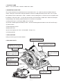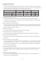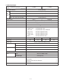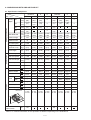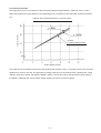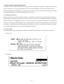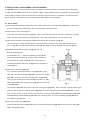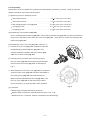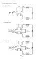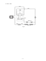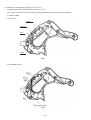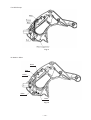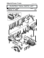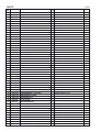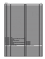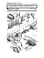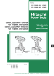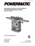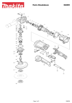
1
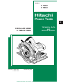
MODELS
C 7SB2
C 7BD2
Hitachi
Power Tools
C
CIRCULAR SAWS
C 7SB2/C 7BD2
LIST Nos. C 7SB2: 0591
C 7BD2: 0592
TECHNICAL DATA
AND
SERVICE MANUAL
Revised Aug. 2005
SPECIFICATIONS AND PARTS ARE SUBJECT TO CHANGE FOR IMPROVEMENT
REMARK:
Throughout this TECHNICAL DATA AND SERVICE MANUAL, a symbol(s)
is(are) used in the place of company name(s) and model name(s) of our
competitor(s). The symbol(s) utilized here is(are) as follows:
Competitors
Symbols Utilized
Company Name
Model Name
C
MAKITA
5007NH
5007NBA
P
DEWALT
DW368
DW369CS
CONTENTS
Page
1. PRODUCT NAME ............................................................................................................................ 1
2. MARKETING OBJECTIVE .............................................................................................................. 1
3. APPLICATIONS ............................................................................................................................... 1
4. SELLING POINTS ........................................................................................................................... 1
4-1. Selling Point Descriptions ................................................................................................................ 2
5. SPECIFICATIONS ........................................................................................................................... 3
6. COMPARISONS WITH SIMILAR PRODUCT ................................................................................. 4
6-1. Specification Comparison ................................................................................................................ 4
6-2. Practical Test Data ............................................................................................................................5
7. PRECAUTIONS IN SALES PROMOTION ...................................................................................... 6
7-1. Handling Instructions ........................................................................................................................6
7-2. Caution Plate ....................................................................................................................................6
7-3. Do Not Use Cut-Off Wheels ..............................................................................................................7
8. PRECAUTIONS IN DISASSEMBLY AND REASSEMBLY ............................................................. 8
8-1. Disassembly ..................................................................................................................................... 8
8-2. Reassembly ...................................................................................................................................... 9
9. STANDARD REPAIR TIME (UNIT) SCHEDULES ........................................................................ 15
Assembly Diagram for C 7SB2
Assembly Diagram for C 7BD2
1. PRODUCT NAME
Hitachi 7-1/4" Circular Saws, Models C 7SB2 and C 7BD2
2. MARKETING OBJECTIVE
The current mainstream of professional-use circular saws is the 7-1/4 " (185 mm) class in the North America
market. Although we have been selling the Models C 7SB and C 7BD (with brake) of this class, over 10 years
have passed since the sales start in 1989. In addition, recently redesigned C, P and E are more competitive than
the Models C 7SB and C 7BD. To cope with this situation, the new Models C 7SB2 and C 7BD2 are developed
corresponding to the following market demands for convenience of operation.
(1) High-power input: 1710 W (only GBR (110 V): 1670 W)
(2) 24-tooth carbide-tipped saw blade (for USA. 18-tooth carbide-tipped saw blade for AUS, NZL and Europe)
(3) AC/DC switch
(4) Bevel adjustment lever
(5) Base with scale
(6) 55˚ bevel capacity (for U.S.A., AUS and NZL. Europe: 45˚)
(7) Soft grip handle
3. APPLICATIONS
Cutting of various types of wood materials
4. SELLING POINTS
Soft and comfortable grip
High-power input motor: 1710 W
(GBR (110 V): 1670 W)
Lightweight: 10.1 lbs. (4.6 kg)
(C 7SB: 10.6 lbs. (4.8 kg))
AC/DC SW
Electric brake for rapid
stopping of saw blade
(Model C 7BD2 only)
55˚ bevel capacity
(for USA, AUS and
NZL)
Magnesium gear cover,
blade cover and
lower guard
24-tooth carbide-tipped
saw blade (for USA)
Easy access bevel
adjustment with lever
Heavy duty aluminum
base with scale
Easy access cutting
depth adjustment
--- 1 ---
4-1. Selling Point Descriptions
(1) Lightweight, 10.1 lbs. (4.6 kg)
The motor is enlarged to increase the input and output power. The gear cover, blade cover and lower guard
are made of magnesium diecasting alloy to minimize increase of the product weight. The table below shows a
weight comparison with C (catalog weight 10.1 lbs., measured weight 10.6 lbs.).
Maker
Hitachi
Model
C 7SB2
Hitachi
C 7BD2
C 7SB
C 7BD
C
5007NH 5007NBA
Catalog weight
lbs. (kg)
10.1 (4.6)
10.6 (4.8)
10.1 (4.6) 11.0 (5.0)
Measured weight
lbs. (kg)
10.6 (4.8)
10.6 (4.8)
10.6 (4.8) 11.0 (5.0)
Weight excludes cord.
(2) AC/DC switch (110 V and 120 V only)
The same AC/DC switch as the one used in the conventional Models C 7SB and C 7BD is adopted to
correspond to the customer demand. The Models C 7SB2 and C 7BD2 are operable on a DC power supply
such as a generator on a building site.
(3) 24-tooth carbide tipped saw blade (for USA)
The Models C 7SB2 for USA and C 7BD2 are equipped with the 24-tooth carbide tipped saw blade that is the
current mainstream of standard saw blade. Green urethane painting is applied on the surface to distinguish
the Hitachi saw blade from others at a glance.
(4) Soft and comfortable grip
The non-slip, soft and comfortable grip is adopted to improve the operability.
(5) High-power input motor: 1710 W (GBR (110 V): 1670 W)
The Models C 7SB2 and C 7BD2 are equipped with the high-power motor to increase the cutting ability.
(6) Easy access bevel adjustment with lever
The conventional wing bolt type bevel adjustment system is changed to the lever type for convenient bevel
adjustment.
(7) 55˚ bevel capacity (for USA, AUS and NZL)
The bevel angle between the saw blade and the base is adjustable from 0˚ to 55˚ for wider application range
(conventional Models C 7SB and C 7BD: 0˚ to 45˚). For ease of operation, the adjustment section is divided
into two ranges; one is adjustable from 0˚ to 45˚ for comparatively frequent use and the other is adjustable
from 45˚ to 55˚ for less frequent use.
(8) Heavy-duty aluminum base with scale
The Models C 7SB2 and C 7BD2 are equipped with the heavy-duty aluminum die-cast base that is the same
as the Models C 7SB and C 7BD. In addition, this base has scales at the front and the side for ease of
operation.
(9) Easy access cutting depth adjustment
The position of the cutting depth adjustment lever is shifted from the gear cover side to the outside of the
handle for easier cutting depth adjustment.
--- 2 ---
5. SPECIFICATIONS
Model
C 7BD2
C 7SB2
Item
Saw blade diameter
7-1/4" (185 mm)
at 90˚
2-3/8" (60 mm)
Max.
at 45˚
cutting
depth at 50˚ (for USA, AUS and NZL)
1-27/32" (47 mm)
at 55˚ (for USA, AUS and NZL)
1-17/32" (39 mm)
1-11/16" (43 mm)
Electric brake
None
Power source
AC single-phase 50/60 Hz (120 V AC/DC)
Type of motor
AC single phase commutator motor
Type of switch
Trigger switch
Enclosure
Housing
Handle cover
Grip cover
Gear cover
Blade cover
Lower guard
Base
Equipped
Polycarbonate resin
Polycarbonate resin
Polycarbonate resin, elastomer
Die-cast magnesium alloy
Die-cast magnesium alloy
Die-cast magnesium alloy
Die-cast aluminum alloy
Voltage [V]
110
120
230
240
Current [A]
16
15
7.8
7.5
Power input
Rotation speed
Weight
1710 W, 1670 W (for GBR (110 V))
No-load
5,800/min.
Full-load
3,760/min.
Net
Main body (excludes cord)
Gross
Main body, mold case, others
• • • • • • • • • • • • • • • • • • • • • • • •
10.1 lbs. (4.6 kg)
16.3 lbs. (7.4 kg)
Mold case
Packing
Cord
• • • • • • • • • • • • • • • • • • • • • • • • • • • •
Type
Two-core cabtire cable
Overall length
8.2 ft. (2.5 m)
Standard accessories
Tungsten carbide tipped saw blade
Box wrench
Guide (for AUS, NZL and Europe)
Mold case
• • • • • • • • • • • • • • • • • • • • • • • • • • • • • • • • • • • • • • • • • • •
• • • • • • • • • • • • • • • • • • • • • • • • • • • • • • • • • • • • • • • • • • • • • • • • • • • • • • • • • • • • • • • • • • • • • • • • • • • ••
• • • • • • • • • • • • • • • • • • • • • • • • • • • • • • • • • • • • • • • • • • • ••
•••••••••••••••••••••••••••••••••••••••••••••••••••••••••••••••••••••••••••••••
Optional accessories
Guide
• • • • • • • • • • • • • • • • • • • • • • • • • • • • • • • • • • • • • • • • • • • • • • • • • • • • • • • • • • • • • • • • • • • • • • • • • • • • • • • • • • • • • •
--- 3 ---
1
1
1
1
1
6. COMPARISONS WITH SIMILAR PRODUCT
6-1. Specification Comparison
Maker • Model
Item • Unit
Cutting
depth
90˚
45˚
Catalog specifications
50˚
55˚
C 7SB
2-3/8
(60)
2-3/8
(60)
in. 1-27/32
(47)
(mm)
in. 1-11/16
(mm)
(43)
in. 1-17/32
(mm)
(39)
1-27/32
(47)
5007NH DW368
2-3/8
(60)
1-3/4
(44)
1-19/32
(40)
HITACHI
C 7BD2
C
P
*1
2-3/8
(60)
C 7BD
2-3/8
(60)
*1
1-27/32
(47)
1-27/32
(47)
*1
1-11/16
(43)
*1
*1
1-17/32
(39)
*1
5007NBA DW369CS
2-3/8
(60)
1-3/4
(46)
*1
*1
in.
(mm)
7-1/4
(185)
7-1/4
(185)
7-1/4
(185)
7-1/4
(184)
7-1/4
(185)
7-1/4
(185)
7-1/4
(185)
7-1/4
(184)
Rated voltage
V
120
115
120
120
120
115
115
120
Rated current
A
15
13
15
15
15
13
13
15
No-load speed
/min.
5,800
5,500
5,800
5,800
5,800
5,500
5,800
5,800
Weight
(exclude cord)
lbs.
(kg)
ft
(m)
10.1
(4.6)
8.2
(2.5)
10.6
(4.8)
8.2
(2.5)
10.1
(4.6)
8.7
(2.65)
9.5
(4.3)
9.0
(2.75)
10.1
(4.6)
8.2
(2.5)
10.6
(4.8)
8.2
(2.5)
11.0
(5.0)
9.5
(2.9)
9.8
(4.4)
9.0
(2.75)
/min.
5,490
5,380
5,680
5,400
5,490
5,380
5,560
5,400
Full-load speed /min.
3,760
4,050
4,050
3,760
3,760
4,050
4,040
3,760
ft-lbs.
(N•m)
1.72
(2.33)
1.23
(1.67)
1.60
(2.17)
1.73
(2.34)
1.72
(2.33)
1.23
(1.67)
1.25
(1.70)
1.73
(2.34)
Max. output
W
2,100
1,680
2,150
2,060
2,100
1,680
1,880
2,060
No-load noise
dB
92
90
92.5
88
92
90
90
88
Power source
AC/DC
AC
AC/DC
AC/DC
AC/DC
AC
AC
AC/DC
Electric brake
None
None
None
None
Equipped
Equipped
Equipped Equipped
Aluminum
diecast
Aluminum
diecast
Aluminum Magnesium Aluminum
diecast
diecast
plate
Aluminum
diecast
Aluminum
plate
Composit
Front
Equipped
None
Equipped
None
Equipped
None
Equipped
None
Side
Equipped
None
Equipped
Equipped
Equipped
None
Equipped
Equipped
Equipped
None
None
None
Equipped
None
None
None
Bevel adjustment
Lever
Wing bolt
Lever
Wing bolt
Lever
Wing bolt
Wing bolt
Lever
Bevel capacity
55˚
45˚
50˚
56˚
55˚
45˚
45˚
56˚
L: 305
H: 255
W: 245
L: 300
H: 242
W: 238
L: 305
H: 255
W: 235
L: 300
H: 260
W: 240
L: 305
H: 255
W: 245
L: 300
H: 242
W: 238
L: 300
H: 255
W: 235
L: 300
H: 260
W: 240
No-load speed
Full-load torque
Material of base
Base
scale
Soft grip
Structure
C 7SB2
P
C
Saw blade dia.
Cord length
Characteristic
in.
(mm)
HITACHI
Unit: mm
L
H
W
Service life of the
carbon brush
hr
150
150
*: These numeric values are for the models destined for the USA.
Refer to "5. SPECIFICATIONS" as the capacities are different depending on the destinations.
--- 4 ---
6-2. Practical Test Data
The graph below shows a comparison of practical cutting data among the Model C 7SB2 (for USA), C and P.
(Note that the practical cutting data may vary depending on the conditions of the saw blade, workpiece material,
etc.)
Hemlock spruce (thickness 60 mm), vertical cutting
P:
Load current (A)
C:
HITACHI
C 7SB2/C 7BD2 (for USA)
Cutting speed (m/min.)
This graph shows the relation between the cutting speed and the load current. If the load current is low, the load
applied to the motor is also low, and generally the cutting capacity is more excellent when comparing the cutting
capacity at the same speed. Although the Model C 7SB2, C and P have almost the equivalent cutting capacity,
the Model C 7SB2 has the most excellent cutting capacity as shown in the above graph.
--- 5 ---
7. PRECAUTIONS IN SALES PROMOTION
In the interest of promoting the safest and most efficient use of the Models C 7SB2 and C 7BD2 Circular Saws by
all of our customers, it is very important that at the time of sale the salesman carefully ensures that the buyer
seriously recognizes the importance of the contents of the Instruction Manual, and fully understands the meaning
of the precautions listed on the Name Plate attached to each tool.
7-1. Handling Instructions
Although every effort is made in each step of design, manufacture, and inspection to provide protection against
safety hazards, the dangers inherent in the use of any electric tool cannot be completely eliminated. Accordingly,
general precautions and suggestions for the use of electric power tools, and specific precautions and suggestions
for the use of the Circular Saw are listed in the Instruction Manual to enhance the safe, efficient use of the tool by
the customer. Salespersons must be thoroughly familiar with the contents of the Handling Instructions to be able
to offer appropriate guidance to the customer during sales promotion.
7-2. Caution Plate
The following basic safety precautions are listed on the Name Plate attached to the main body of each tool.
For the U.S.A.
For AUS/NZL
--- 6 ---
For Europe
7-3. Do Not Use Cut-Off Wheels
The Models C 7SB2 and C 7BD2 are not designed for use with cut-off wheels (grindstones). The customers must
be cautioned that the use of a cut-off wheel would be extremely dangerous.
--- 7 ---
8. PRECAUTIONS IN DISASSEMBLY AND REASSEMBLY
The [Bold] numbers in the descriptions below correspond to the item numbers in the Parts List for the Model
C 7SB2, and the <Bold> numbers for the Model C 7BD2. During disassembly and reassembly, and at all other
times as well, sufficient care must be exercised in handling to ensure that is no deviation in the flatness of the
bottom surface of the base and in its perpendicularity with relation to the saw blade.
8-1. Disassembly
(1) Prior to attempting further disassembly, ensure without fail that the TCT Saw Blade [14] <14> is removed to
prevent damage to its cutting edge, and to avoid possible serious accident.
(2) Remove the Lower Guard [7] <7>:
First, disconnect the Return Spring [8] <8>. Then, loosen the two Seal Lock Flat Hd. Screws M4 x 10 [12]
<12>, and take off the Bearing Cover [11] <11>. The Lower Guard [7] <7> can then be removed.
(3) Remove the Bearing Holder [3] <3> together with the Spindle and Gear Set [2] <2>:
After removing the Lower Guard [7] <7> as described above, loosen the two Seal Lock Flat Hd. Screws
M5 x 14 [4] <4>, and take off the Bearing Holder [3] <3> together with the Spindle and Gear Set [2] <2>.
Push
(4) Separate the Spindle and Gear Set [2] <2> from the
Bearing Holder [3] <3>:
As illustrated in Fig. 1, support the Bearing Holder [3] <3>
with an appropriate tubular jig, and push down on the end
Jig
of the Spindle and Gear Set [2] <2> with a hand press to
separate the Spindle and Gear Set [2] <2> from the Bearing
(5) Remove the Armature [29] <29>:
First, remove the Carbon Brushes (1 Pair) [43] <43>. Next,
60 mm
(2-23/64")
Holder [3] <3>.
take off Lever (A) W/O Stopper [68] <69>, loosen the Long Nut
[67] <68>, and remove the Bolt (Square) M6 x 20 [39] <39>.
Then, loosen the Machine Screws (W/Washers) M5 x 55 [20]
<20>, and separate the Housing Ass'y [22] <22> from the Gear
49 mm
(1-15/16")
Fig. 1
Cover [34] <34>.
The Armature [29] <29> will remain within the Housing Ass'y [22] <22>. With a wooden or plastic hammer, tap
gently on the outside of the Housing Ass'y [22] <22> to loosen and remove the Armature [29] <29>. At this
time, be very careful not to hit the fan on the armature. Remove the Ball Bearing 6000VVCMPS2L [23] <23>
and Ball Bearing 6202VVCMPS2L [32] <32> with a bearing puller, and remove Washer (A) [24] <24> and
Dust Washer (B) [31] <31>.
(6) Remove the Base Ass'y [59] <60>:
Extract the Roll Pin D6 x 40 [62] <63> which connects the Base Ass'y [59] <60> and the Housing Ass'y [22]
<22>, and separate them.
--- 8 ---
8-2. Reassembly
Reassembly can be accomplished by following the disassembly procedures in reverse. However, particular
attention should be given to the following items.
(1) Tightening torque for fastening screws:
M4 machine screws
•••••••••••••••••••••••••• • • • • • • • • • • • • • • • • • • • • • • • • •
1.8
0.4 N•m (12 to 19 in-lbs.)
M5 machine screws
•••••••••••••••••••••••••• • • • • • • • • • • • • • • • • • • • • • • • • •
3.4
0.7 N•m (24 to 36 in-lbs.)
••••••••••••••••••••••••••
9.8
2.0 N•m (70 to 105 in-lbs.)
D4 tapping screw
•••••••••••••••••••••••••••••••••••••••••••••••••••••••
2.0
0.5 N•m (13 to 22 in-lbs.)
D5 tapping screw
•••••••••••••••••••••••••••••••••••••••••••••••••••••••
2.9
0.5 N•m (22 to 30 in-lbs.)
Bolt (W/Flange) M8 x 15.5 [16] <16>
(2) Reassembly of the Armature [29] <29>:
Prior to assembling the Armature [29] <29>, ensure that the Rubber Ring [33] <33> is properly inserted into
the groove of the bearing case within the Gear Cover [34] <34>. At this time, be careful not to damage the
Rubber Ring [33] <33>.
(3) Reassembly of the Lock Lever [30] <30>: (See Fig. 2.)
A. Position the Lock Lever [30] <30> between the fan and
the Ball Bearing 6202VVCMPS2L [32] <32>, and
carefully assemble it together with the Armature [29]
<29> into the Gear Cover [34] <34>.
B. Carefully ensure that both ends of the flat spring on
the Lock Lever [30] <30> are properly supported inside
the ribs of the Gear Cover [34] <34>, as illustrated in
Fig. 2.
C. When assembly of the Lock Lever [30] <30> is completed
(when the Gear Cover [34] <34> has been assembled to
the Housing Ass'y [22] <22> and fastened with the
Machine Screws (W/Washers) M5 x 55 [20] <20>, push
the Lock Lever [30] <30> by hand and ensure that it
returns smoothly to its original position when released.
Fig. 2
(4) Lubrication:
Liberally apply designated lubricants as follows:
Nippeco SEP-3A (Code No. 930035) within the gear cover: 10 gr.
Multemp PS No. 2 (Code No. 939301 or 939536) in the ball bearings.
--- 9 ---
(5) Wiring diagrams (See Figs. from 3 to 6.):
A. Model C 7SB2
For the U.S.A.
SW
Black
Stator coil
Power
source
White
Black
Stator coil
Red
Fig. 3
For AUS/GBR (110 V)
Fig. 4
For NZL/Europe
Fig. 5
--- 10 ---
B. Model C 7BD2
Black
Blue
Power
source
Yellow
Brake coil
White
Black
Stator coil
Fig. 6
--- 11 ---
(6) Internal wire arrangement (See Figs. from 7 to 10.):
Connect internal wires as illustrated in Figs. from 7 to 10.
At this time, ensure that none of the wires are pinched between components during reassembly.
A. Model C 7SB2
For the U.S.A.
Black
White
Red
Black
Fig. 7
For AUS/GBR (110 V)
Fig. 8
--- 12 ---
For NZL/Europe
Fig. 9
B. Model C 7BD2
Black
Blue
Yellow
White
Black
Fig. 10
--- 13 ---
(7) Insulation tests:
On completion of disassembly and repair, measure the insulation resistance and conduct dielectric strength
test.
Insulation resistance: 7 M Ω or more with DC 500 V Megohm Tester
Dielectric strength: AC 2,500V/1 minute,
with no abnormalities
(8) Cleaning the cover:
Clean the exterior of the tool with a soft cloth moistened with soapy water, and dry thoroughly.
Chloric solvent, gasoline, and thinner will cause plastic components to dissolve.
--- 14 ---
9. STANDARD REPAIR TIME (UNIT) SCHEDULES
MODEL
Variable
Fixed
10
20
30
Work Flow
C 7SB2
C 7BD2
Switch
Cord
Housing Ass'y
Stator Ass'y
General Assembly
Safety Cover
Return Spring
Armature
Ball Bearing
(6202VV)
Ball Bearing
(6000VV)
Gear Cover
Spindle and
Gear Set
Ball Bearing
(6003VV)
Needle Bearing
Base Ass'y
--- 15 ---
40
50
60 min.
Hitachi Power Tools
LIST NO. 0591
ELECTRIC TOOL PARTS LIST
CIRCULAR SAW
Model C 7SB2
502
501
2005
7•8
•
(E2)
503
17
15
16
19
14
12
18
13
11
10
9
8
7
6
5
4
36
3
2
34
37
38
35
69
1
70
33
30
32
31
29
39
28
26
21
22
23
24
27
25
72
57A
71
58
20
56A
59
60
50
61
62
49
48
47
41
74
42
43
66
44
45
53
46
52
51
64
63
65
60
73
40
63
58
54
67
68
55A
PARTS
ITEM
NO.
1
C 7SB2
CODE NO.
NO.
USED
DESCRIPTION
982-027
NEEDLE BEARING (HK1010)
1
2
320-960
SPINDLE AND GEAR SET
1
3
302-433
BEARING HOLDER
1
4
992-013
SEAL LOCK FLAT HD. SCREW M5X14
2
5
600-3VV
BALL BEARING 6003VVCMPS2L
1
6
961-807
BUSHING
1
7
320-956
LOWER GUARD
1
8
320-968
RETURN SPRING
1
9
320-957
LEVER
1
10
935-196
MACHINE SCREW (W/WASHERS) M4X12 (BLACK)
1
11
302-435
BEARING COVER
1
REMARKS
12
990-430
SEAL LOCK FLAT HD. SCREW M4X10
2
*
13
320-970
WASHER (A)
1
*
13
321-639
WASHER (A)
1
FOR AUS, NZL
*
13
324-597
WASHER (A)
1
FOR EUROPE
*
14
320-843
TCT SAW BLADE 185MM-D16 HOLE-NT24
1
*
14
302-411
TCT SAW BLADE 185MM-D20 HOLE-NT18
1
FOR AUS, NZL
*
14
302-412
TCT SAW BLADE 185MM-D30 HOLE-NT18
1
FOR EUROPE
*
15
320-953
WASHER (B)
1
*
15
324-598
WASHER (B)
1
16
320-971
BOLT (W/FLANGE) M8X15.5
1
17
324-594
BLADE COVER
1
18
951-039
MACHINE SCREW (W/SP. WASHER) M4X12
3
HITACHI LABEL
1
308-357
MACHINE SCREW (W/WASHERS) M5X55
3
NAME PLATE
1
22
320-951
HOUSING ASS’Y
1
23
600-0VV
BALL BEARING 6000VVCMPS2L
1
24
302-428
WASHER (A)
1
19
20
21
FOR EUROPE
INCLUD. 40, 42
25
937-623
BRUSH TERMINAL
2
26
930-804
TERMINAL M4.0 (10 PCS.)
2
*
27
340-638G
STATOR ASS’Y 110V
1
INCLUD. 25, 26
*
27
340-528C
STATOR ASS’Y 120V
1
INCLUD. 25, 26
*
27
340-528G
STATOR ASS’Y 220V-230V
1
INCLUD. 25, 26
*
27
340-528H
STATOR ASS’Y 240V
1
INCLUD. 25, 26
28
320-958
FAN GUIDE
1
*
29
360-577U
ARMATURE ASS’Y 110V-120V
1
*
29
360-577G
ARMATURE 220V-230V
1
*
29
360-577H
ARMATURE 240V
1
30
320-959
LOCK LEVER
1
31
980-700
DUST WASHER (B)
1
32
620-2VV
BALL BEARING 6202VVCMPS2L
1
33
303-792
RUBBER RING
1
*
34
320-954
GEAR COVER
1
*
34
324-600
GEAR COVER
1
35
311-837
SPACER M4
1
36
311-836
TP-SCREW M4X14
1
37
961-729
CUSHION
1
38
949-794
FLAT HD. SCREW M6X20 (10 PCS.)
1
39
942-808
BOLT (SQUARE) M6X20
1
40
938-477
HEX. SOCKET SET SCREW M5X8
2
--- 2 ---
INCLUD. 23, 24, 31, 32
FOR EUROPE
* ALTERNATIVE PARTS
7 -- 05
PARTS
ITEM
NO.
41
C 7SB2
DESCRIPTION
NO.
USED
301-653
TAPPING SCREW (W/FLANGE) D4X20 (BLACK)
5
42
938-241
BRUSH HOLDER
2
43
999-038
CARBON BRUSH (1 PAIR)
2
CODE NO.
REMARKS
44
945-161
BRUSH CAP
2
*
45
958-049
CORD ARMOR D8.2
1
*
45
940-778
CORD ARMOR D10.7
1
*
46
500-453Z
CORD
1
(CORD ARMOR D10.7)
*
46
500-439Z
CORD
1
(CORD ARMOR D8.2) FOR AUS, NZL
*
46
500-435Z
CORD
1
(CORD ARMOR D8.2) FOR GBR (230V)
*
46
500-463Z
CORD
1
(CORD ARMOR D10.7) FOR GBR (110V)
*
46
500-234Z
CORD
1
(CORD ARMOR D8.2) FOR EUROPE
*
47
930-804
TERMINAL M4.0 (10 PCS.)
2
*
47
980-063
TERMINAL
2
48
937-631
CORD CLIP
1
49
984-750
TAPPING SCREW (W/FLANGE) D4X16
2
50
953-121
HEX. HD. TAPPING SCREW D5X50
2
51
320-969
SWITCH (2P SCREW TYPE)
1
52
305-720
TAPPING SCREW (W/FLANGE) D4X12
1
53
320-952
HANDLE COVER
1
54
320-967
GRIP COVER
1
55A
322-260
SEAL LOCK SCREW (W/SP. WASHERS) M6X14
1
56A
322-600
LEVER (A) W/STOPPER
1
57A
322-261
LOCK NUT SET (W/SCREW)
1
FOR AUS, NZL, EUROPE
58
320-975
WASHER
2
*
59
320-961
BASE ASS’Y
1
INCLUD. 55-58, 60, 61, 63-66
*
59
324-599
BASE ASS’Y
1
INCLUD. 55-58, 60, 61, 63-66, 71-74
FOR EUROPE
60
319-541
SEAL LOCK HEX. SOCKET SET SCREW M5X6
2
61
320-962
BEVEL PLATE
1
62
949-686
ROLL PIN D6X40 (10 PCS.)
1
63
320-163
STEP PIN D6X13
2
64
942-808
BOLT (SQUARE) M6X20
1
65
320-963
LINK
1
66
308-109
SLOTTED HD. SET SCREW (SEAL LOCK) M6X8
1
67
320-966
LONG NUT
1
68
322-601
LEVER (A) W/O STOPPER
1
*
69
324-596
PLATE
1
FOR EUROPE
*
70
958-523
MACHINE SCREW (W/SP. WASHER) M4X8
2
FOR EUROPE
*
71
324-595
STOPPER
1
FOR EUROPE
*
72
958-523
MACHINE SCREW (W/SP. WASHER) M4X8
1
FOR EUROPE
*
73
301-806
WING BOLT M6X15
1
FOR AUS, NZL, EUROPE
*
74
947-859
LOCK SPRING
1
FOR AUS, NZL, EUROPE
7 -- 05
* ALTERNATIVE PARTS
--- 3 ---
C 7SB2
STANDARD ACCESSORIES
ITEM
NO.
501
*
CODE NO.
DESCRIPTION
NO.
USED
REMARKS
321-188
CASE
1
502
940-543
BOX WRENCH 10MM
1
503
302-691
GUIDE
1 FOR AUS, NZL, EUROPE
OPTIONAL ACCESSORIES
ITEM
NO.
601
--- 4 ---
CODE NO.
302-691
DESCRIPTION
GUIDE
NO.
USED
REMARKS
1
* ALTERNATIVE PARTS
Printed in Japan
(050708N)
7 -- 05
Hitachi Power Tools
LIST NO. 0592
ELECTRIC TOOL PARTS LIST
CIRCULAR SAW
Model C 7BD2
2005
(E2)
17
16
502
501
8 • 10
•
19
15
14
18
13
12
11
10
9
8
7
6
38
5
37
4
3
35
2
36
34
1
32
33
31
30
29
28
27
39
26
25
24
23
22
21
58A
20
59
57A
48
49
50
60
61
62
51
63
47
64
65
64
66
61
40
41
42
43
67
44
45
54
46
53
52
55
59
68
69
56A
PARTS
ITEM
NO.
1
C 7BD2
CODE NO.
NO.
USED
DESCRIPTION
982-027
NEEDLE BEARING (HK1010)
1
2
320-960
SPINDLE AND GEAR SET
1
3
302-433
BEARING HOLDER
1
4
992-013
SEAL LOCK FLAT HD. SCREW M5X14
2
5
600-3VV
BALL BEARING 6003VVCMPS2L
1
6
961-807
BUSHING
1
7
320-956
LOWER GUARD
1
8
320-968
RETURN SPRING
1
9
320-957
LEVER
1
10
935-196
MACHINE SCREW (W/WASHERS) M4X12 (BLACK)
1
11
302-435
BEARING COVER
1
12
990-430
SEAL LOCK FLAT HD. SCREW M4X10
2
13
320-970
WASHER (A)
1
14
320-843
TCT SAW BLADE 185MM-D16 HOLE-NT24
1
15
320-953
WASHER (B)
1
16
320-971
BOLT (W/FLANGE) M8X15.5
1
17
324-594
BLADE COVER
1
18
951-039
MACHINE SCREW (W/SP. WASHER) M4X12
3
HITACHI LABEL
1
308-357
MACHINE SCREW (W/WASHERS) M5X55
3
NAME PLATE
1
22
320-951
HOUSING ASS’Y
1
23
600-0VV
BALL BEARING 6000VVCMPS2L
1
24
302-428
WASHER (A)
1
25
937-623
BRUSH TERMINAL
2
26
930-804
TERMINAL M4.0 (10 PCS.)
27
340-527C STATOR ASS’Y 120V
28
320-958
29
360-577U ARMATURE ASS’Y 110V-120V
30
320-959
LOCK LEVER
1
31
980-700
DUST WASHER (B)
1
32
620-2VV
BALL BEARING 6202VVCMPS2L
1
33
303-792
RUBBER RING
1
34
320-954
GEAR COVER
1
19
20
21
INCLUD. 40, 42
2
1
FAN GUIDE
INCLUD. 25, 26
1
1
35
311-837
SPACER M4
1
36
311-836
TP-SCREW M4X14
1
37
961-729
CUSHION
1
38
949-794
FLAT HD. SCREW M6X20 (10 PCS.)
1
39
942-808
BOLT (SQUARE) M6X20
1
40
938-477
HEX. SOCKET SET SCREW M5X8
2
41
301-653
TAPPING SCREW (W/FLANGE) D4X20 (BLACK)
5
42
938-241
BRUSH HOLDER
2
43
999-038
CARBON BRUSH (1 PAIR)
2
44
945-161
BRUSH CAP
2
45
940-778
CORD ARMOR D10.7
1
46
500-453Z
CORD
1
47
930-804
TERMINAL M4.0 (10 PCS.)
1
48
938-307
PILLAR TERMINAL
1
49
937-631
CORD CLIP
1
50
984-750
TAPPING SCREW (W/FLANGE) D4X16
2
51
953-121
HEX. HD. TAPPING SCREW D5X50
2
--- 2 ---
REMARKS
INCLUD. 23, 24, 31, 32
(CORD ARMOR D10.7)
* ALTERNATIVE PARTS
8 -- 05
PARTS
ITEM
NO.
52
C 7BD2
CODE NO.
NO.
USED
DESCRIPTION
320-950
SWITCH (1P SCREW TYPE)
1
53
305-720
TAPPING SCREW (W/FLANGE) D4X12
1
54
320-952
HANDLE COVER
1
55
320-967
GRIP COVER
1
56A
322-260
SEAL LOCK SCREW (W/SP. WASHERS) M6X14
1
57A
322-600
LEVER (A) W/STOPPER
1
58A
322-261
LOCK NUT SET (W/SCREW)
1
59
320-975
WASHER
2
60
320-961
BASE ASS’Y
1
61
319-541
SEAL LOCK HEX. SOCKET SET SCREW M5X6
2
62
320-962
BEVEL PLATE
1
63
949-686
ROLL PIN D6X40 (10 PCS.)
1
64
320-163
STEP PIN D6X13
2
65
942-808
BOLT (SQUARE) M6X20
1
66
320-963
LINK
1
67
308-109
SLOTTED HD. SET SCREW (SEAL LOCK) M6X8
1
68
320-966
LONG NUT
1
69
322-601
LEVER (A) W/O STOPPER
1
8 -- 05
REMARKS
INCLUD. 56-59, 61, 62, 64-67
* ALTERNATIVE PARTS
--- 3 ---
C 7BD2
STANDARD ACCESSORIES
ITEM
NO.
501
502
CODE NO.
DESCRIPTION
NO.
USED
321-188
CASE
1
320-976
WRENCH 10MM
1
REMARKS
OPTIONAL ACCESSORIES
ITEM
NO.
601
--- 4 ---
CODE NO.
302-691
DESCRIPTION
GUIDE
NO.
USED
REMARKS
1
* ALTERNATIVE PARTS
Printed in Japan
(050810N)
8 -- 05