1
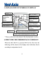
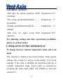
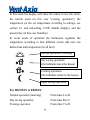
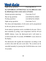
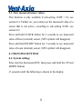
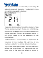
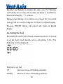
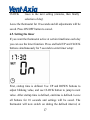
User Manual
1. Product description - Area of use. . . . . . . . . . .
2. Technical data. . . . . . . . . . . . . . . . . . . . . . . . . . .
3. Explanations of the symbols in display . . . . . .
4. First time the thermostat is turned on. . . . . . .
5. Operation of the thermostat. . . . . . . . . . . . . . .
5.1. Constant temperature mode . . . . . . . . .
5.2. Event based mode. . . . . . . . . . . . . . . . . .
5.3. View measured sensor values. . . . . . . . .
6. Changing settings. . . . . . . . . . . . . . . . . . . . . . . .
6.1. System settings. . . . . . . . . . . . . . . . . . . . .
6.2. Sub-settings, parameters . . . . . . . . . . . .
6.3. Event mode settings . . . . . . . . . . . . . . . .
6.4. Setting the clock . . . . . . . . . . . . . . . . . . .
6.5. Setting the timer . . . . . . . . . . . . . . . . . . .
7. Error messages. . . . . . . . . . . . . . . . . . . . . . . . . .
8. Resetting the thermostat. . . . . . . . . . . . . . . . . .
2
3
5
5
7
8
8
11
11
11
12
14
16
17
18
18
Installation instructions
19
1
1. PRODUCT DESCRIPTION – AREA OF USE
Thermostat for regulating underfloor electric heating cables,
temperature range within +5 to +40 °C (default). Ref 446174 is
programmable, and regulate the room or floor temperature
automatically. The thermostat can operate in two modes,
constant temperature mode or event mode.
From the factory Ref 446174 will start and run in constant
temperature mode using the room sensor (internal sensor) by
default. The temperature is set by the user, according to his/her
needs at any given time. If switched to event mode the
temperature target will be changed according to the default
program as shown in section 4. In event mode the thermostat
controls the temperature according to time and day. For
weekdays and weekend, different temperatures can be set at
different times. In this way it is possible to reduce the output
during night and day when the user does not need comfort
temperature (automatically). Energy consumption can be
reduced considerably. Please see section 6.3. for settings and
event mode programming.
The thermostat has a (built-in) room sensor and is delivered
2
with an external sensor which should be placed (embedded)
into the floor between two heating cable loops, near the floor
surface. Temperature can be regulated by the floor sensor or
the room sensor. A combination mode is also available where
both sensors are used. The floor sensor can then be used to
limit the floor temperature (below the set maximum limit), the
room sensor is used for regulating temperature according to the
set value.
If the heat indication symbol is shown in the display, it means
the thermostat is heating, but the symbol is not directly linked
(synchronized) to the relay controlling the power to the heating
cable.
The thermostat is turned on and off by using the ON/OFF
button. When turned off the settings will be remembered. The
thermostat will also remember its' settings if the power supply
fails (no time limit, EEPROM backup).
2. TECHNICAL DATA
Rated voltage
220-240V
Own consumption
<2W
3
Maximum load
16A(approx. 3600W at rated voltage)
Switch (ON/OFF)
Electronic
Temperature range
Designed working
temperatures
From +5°C to +40°C
(+41°F to +104°F) (default)
1-50 °C (Room sensor)
for sensors
1-80 °C (Floor sensor)
Dimensions
84x84x40mm(25 mm socket)
Encapsulation
IP 21
Length floor sensor
cable
Cross section area,
connecting wires
Max. number of
heating cables
3m
0,5 mm² - 2,5 mm²
3
Sensing element
NTC
Display
LCD (blue backlighting)
The thermostat is maintenance free.
4
3. EXPLANATION OF SYMBOLS IN DISPLAY
Clock (*)
Day of week (*)
Measured, or set
temperature if
“SET”
is
shown.
Antifreeze (*)
Heat indication
symbol.
Room sensor (*)
Event/operation
mode symbols(*)
Floor sensor (*)
Shown if override
is active
Timer (*)
Shown when setting events/modes.
Shown when adjusting general settings
* These symbols are only shown if the function/state is active.
4. FIRST TIME THE THERMOSTAT IS TURNED ON
When the Ref 446174 is powered ON for the first time the
following will be shown in the display (heat indication shown
according to temperature level):
5
The thermostat is in constant temperature mode.
If switched to event mode the following predefined program
will start running:
MONDAY - FRIDAY:
Start time for normal operation 06.00
Temperature 21°C
(morning)
Start
time
for
day
saving 09.00
Temperature 16°C
operation
Start time for evening operation
Start
time
for
night
17.00
Temperature 21°C
saving 22.00
Temperature 16°C
operation
6
SATURDAY - SUNDAY:
Start time for normal operation 08.00 Temperature 21°C
(morning)
Day saving operation(deactivated -- .--
Temperature -- °C
by default)
Evening operation(deactivated by -- .--
Temperature -- °C
default)
Start
time
for
night
saving 22.00 Temperature 16°C
operation
For adjusting settings and other operational possibilities
please see section 5 and 6.
5. OPERATION OF THE THERMOSTAT
To change between constant temperature mode and event
mode
This function is linked to the clock function. Enter general
settings (See section 6.1) and go to sub-setting 11:CL (clock
settings). If the clock is disabled, the thermostat will run in
constant temperature mode. Event mode is activated by
activating the clock itself, either 12h AM/PM or 24h (See
section 6.1).
7
5.1. Constant temperature mode
The display will show the sensor in use and the temperature (or
the set temperature according to settings, see section 6.1 and
sub-setting 12:DF default display).
The set temperature can be adjusted by the user by pressing the
UP and DOWN buttons.
5.2. Event based mode
The temperature is regulated dependent of time and day (as set
by the user).
8
In this mode the display will show the sensor in use, the clock,
the current event (in this case "evening operation"), the
temperature (or the set temperature according to settings, see
section 6.1 and sub-setting 12:DF default display), and the
present day (in this case Saturday).
In event mode of operation the thermostat regulates the
temperature according to four different events (the user can
define time and temperature for all four):
normal operation / morning
day saving operation
(the habitants leave the house)
evening operation
(the habitants return to the house)
night saving operation
For MONDAY to FRIDAY:
Normal operation (morning)
From time A to B
Day saving operation
From time B to C
Evening operation
From time C to D
9
Night saving operation
From time D to A
For SATURDAY to SUNDAY there are two different events
by default (up to four events can be activated):
Normal operation (morning)
From time E to F
Day saving operation
(not defined by default)
Evening operation
(not defined by default)
Night saving operation
From time F to E
The times and temperatures of all events can be programmed
by the user, please see section 6.3.
Event mode of operation can be overridden by the user. This is
done manually by setting a new temperature with the UP and
DOWN buttons. Leave the thermostat and it will return to
override mode after 10 seconds, OVERRIDE is now shown in
the display.
The thermostat will regulate the temperature according to the
override value until the next event starts. The override can be
cancelled manually by pressing the CLOCK button once (wait
10 seconds).
10
5.3. View measured sensor values
This function is only available if sub-setting 12:DF = 01, see
section 6.2. Further on, you cannot see the measured value of a
sensor that is not active, according to sub-setting 10:SE, see
section 6.2.
Press and hold CLOCK button for 3 seconds to see measured
value of floor (external) sensor. (SET symbol will disappear).
Press and hold ON/OFF button for 3 seconds to see measured
value of room (internal) sensor. (SET symbol will disappear).
6. CHANGING SETTINGS
6.1. System settings
First, turn the thermostat OFF, then press and hold the UP and
DOWN buttons
(5 seconds) until the following is shown in the display.
11
Sub-setting number
Abbrevation for setting
Current parameter,
which can be adjusted.
This is the menu for general settings, containing 12 different
sub-settings. Sub-setting 01:CF is shown first. Pressing the
CLOCK button lets you cycle between the other 12 different
sub-settings. UP and DOWN keys adjust the current parameter
as shown in the display.
6.2. Sub-settings, parameters
01:CF Set whether to show temperatures in Celsius or
Fahrenheit degrees. 00=Celsius, 01= Fahrenheit.
02:DI Shows the dead band range. For information only, the
value cannot be changed.
03:CA Calibration. You can manually set the value of the
current measured temperature. This setting/value applies to
12
both internal and external sensor.
04:FR Antifreeze function. 00=Off, 01=On. If function is on
the antifreeze symbol will be shown in the display. See also
sub-setting 05.
05:FS Temperature limitations, antifreeze and maximum floor
temperature.
05=Basic antifreeze, the thermostat will start heating if the
temperature goes below 5 degree Celsius.
CU=User defined settings. Minimum limits as set in
sub-setting 06 and 08 will be used for antifreeze purposes. In
addition if both sensors are active (sensor mode 02) the
thermostat will limit the maximum floor temperature (using the
floor sensor max value) according to the value set in
sub-setting 09.
Active sensor according to setting 10:SE will be used for
temperature measurement. If sensor mode=02 the room
(internal) sensor will trigger the antifreeze function.
06:RO Defines valid minimum setting/value for room
temperature.
07:RO Defines valid maximum setting/value for room
13
temperature
08:FL Defines valid minimum setting/value for external/floor
temperature.
09:FL Defines valid maximum setting/value for external/floor
temperature.
10:SE Sensor selection. 00=Room sensor, 01=Floor sensor,
02=Both, combination mode. Set active sensor(s) according to
installation instructions.
11:CL Clock. NO=No clock, thermostat will run in constant
temperature mode, 12h=12 hour clock with AM/PM, 24h=24
hour clock without AM/PM displayed. If either 12h or 24h is
active, event mode will also be activated.
12:DF Default display of temperature: set or measured
temperature. 00=display measured temperature, 01=display set
temperature.
Leave all buttons for 10 seconds to save all settings and return
to normal operation mode. The ON/OFF button cancels and
exits the settings menu.
6.3. Event mode settings
14
With the clock activated see section 6.1, you can change the
settings for event mode of operation. Press the CLOCK button
once and the following will be displayed:
You are now adjusting settings for weekdays Monday to Friday,
“Normal operation (morning)”. The start-time will be blinking,
and it can now be changed with UP and DOWN buttons. Press
CLOCK button once to jump to the temperature and use UP
and DOWN buttons to set the temperature for this
event/timeframe.
In other words time A (see section 5.2) is set first, thereafter the
temperature for this timeframe. The end time of each
timeframe is defined by the start time of the next timeframe.
Press CLOCK button again to jump to next event, and thereby
defining time B (see section 5.2), and thereafter the other
events. After all four events are defined the settings for
15
Saturday and Sunday is defined the same way. For Saturday
and Sunday day saving and evening operation is disabled by
default indicated by "- -" symbols.
During programming, if no buttons are pressed for 10 seconds
settings will be saved and display will return to default display.
Pressing ON/OFF button will cancel and return to default
display.
6.4. Setting the clock
Press DOWN and CLOCK button simultaneously for 5 seconds
to set the clock (clock must be active, sub-setting 11:CL). The
following will be displayed:
The hour is set first.
UP
Increases value of blinking parameter
DOWN
Decreases value of blinking parameter
16
CLOCK
Goes to the next setting (minutes, then finally
selection of day)
Leave the thermostat for 10 seconds and all adjustments will be
saved. Press ON/OFF button to cancel.
6.5. Setting the timer
If you want the thermostat active at certain timeframe each day
you can use the timer function. Press and hold UP and CLOCK
buttons simultaneously for 5 seconds to enter timer setup:
First, startup time is defined. Use UP and DOWN buttons to
adjust blinking value, and use CLOCK button to jump to next
value. After startup time is defined, end-time is defined. Leave
all buttons for 10 seconds and settings will be saved. The
thermostat will now switch on during the defined interval, at
17
other times it will be off. Set the startup-time equal to the
end-time to disable the function.
7. ERROR MESSAGES
If there is a fault associated with a sensor either E1 or E2 will
be displayed flashing, along with an indication of which sensor
is faulty. E1 means the sensor connection is short-circuited. E2
means there is an open circuit at the sensor connection.
For example, the message below indicates a short-circuit at the
internal room sensor.
8. RESETTING THE THERMOSTAT
To reset the thermostat to its’ original factory settings turn it off,
18
then hold ON/OFF button and UP button simultaneously for 10
seconds. All LCD symbols will then light up and the default
data is recovered. Release the buttons.
INSTALLATION INSTRUCTIONS
Vent-Axia VAUFHTC Ref 446174
Product description
VAUFHTC Ref 446174 is a digital thermostat for controlling
electrical underfloor heating cables. The thermostat is equipped
with an integrated room sensor and is delivered with an
external (floor) sensor. The thermostat shall be mounted in a
standard junction box.
Technical data
Rated Voltage:
220-240V, 50/60 Hz
Max. load:
3600 W (16 A at 230 VAC)
IP class:
IP 21
19
Temperature range (default):
+5 to +40 °C
Max. circuit breaker size:
16 A
Length of floor sensor:
3m
Cross section of cold lead:
0.5 mm² - 2.5 mm²
Max. No. of heating cables:
3
On/off-switch:
Electronic
Norms/standards:
IEC 60730-1 and IEC 60730-2-9
EMC Directive 89/336
The device is CE-marked. For indoor use only.
Warranty
Vent-Axia offers a 2 year warranty on defects in material and
workmanship in the sold product, under proper use and service.
In case of a defect, Vent-Axia will repair or replace the product.
The warranty does not extend to defects caused by a faulty
installation or improper use.
Vent-Axia must be given written notice of any defect within 30
days after the defect was discovered. Further, a detailed
description of the defect must accompany the claim in order for
the warranty to be valid.
20
Before installing the thermostat
Determine whether the heated floor shall be controlled by
using the room or floor sensor. For guidance, see table 1. Both
sensors can be set active. The room sensor will then be the
primary sensor, and the floor sensor can function as a
temperature limitation sensor, protecting the floor from
overheating. Please see user manual for further details.
The thermostat should be positioned approx. 1.6 m above the
floor. If the room sensor is used, the thermostat must be
positioned so that air freely can flow through the thermostat
chassis. Avoid placing the thermostat in places where it will be
exposed to direct sunlight or draught. Make sure that the
heating cable’s cold lead reaches the planned position of the
thermostat.
If installing floor sensor: Start by following the instructions in
section 1. For installation with room sensor only: Proceed
directly to section 2.
IMPORTANT: All wiring to be in accordance with the current
I.E.E regulations, or appropriate standards of your country and
MUST be installed by a suitably qualified person.
21
All heating cable circuits shall have a 30mA ground fault
circuit interrupter installed.
IMPORTANT: Before installing the thermostat, the power
circuit must be disconnected on phase and neutral. This is done
by switching off or unscrewing the circuit breaker(s). Verify
with a voltmeter that the circuit is completely disconnected by
measuring phase – neutral, phase – ground, and neutral –
ground.
Table 1
Room type
Concrete floor with
tiles, stone or slate,
high area load (100 150 W/m²)
Bathroom
Washroom
Toilet
Wet rooms in general
Floor Room Room Recommended
+
sensor sensor floor heating cable
sensor products from
(limita Vent-Axia
tion-se
nsor)
X
VAUFHC
VAUFHM100/15
0
22
Concrete floor with
tiles, stone or vinyl,
low to medium area
load (60 - 100 W/m²)
Living room
Kitchen
Hall
Sleeping room
Living areas in general
Concrete floor with
parquet or laminate,
low to medium area
load (60 – 100 W/m²)
Living room
Kitchen
Hall
Sleeping room
Living areas in general
Wooden floors, dry
solutions (no need for
concrete/screed).
Low area load 50 –
100 W/m²
Living room
Kitchen
Hall
Sleeping room
Living areas in general
X
VAUFHC
VAUFHM100/15
0
X
X*
VAUFHC
VAFHM100/150
X
X*
VAUFHC
VAFHM100/150
* Required by some parquet/laminate suppliers.
23
1. Installation of the floor sensor
1.1 The floor sensor shall be positioned centered between two
heating cable strings in the floor before pouring concrete
or screed. It is recommended to install the sensor in a
flexible conduit. The conduit should cover the full sensor
length. Seal off the conduit in the (floor) end to prevent
concrete or screed from entering. It is recommended to
position the conduit/sensor as close to the floor surface as
possible (fig. 1)
1.2 Feed the sensor into the conduit so that the sensor itself is
positioned near the end of the conduit in the floor.
1.3 Proceed to section 2.
2. Installation of the thermostat
1.4 Verify that the supplying circuit is completely
disconnected.
1.5 If the heating cables are installed in a wet room (for
example bathroom), the thermostat shall be placed outside
the room. For dry rooms, the thermostat can preferably be
placed inside the room. If the heating cables shall be
24
controlled by using the room sensor, the thermostat must
be placed inside the room.
1.6 Separate the frontside (screen) and the backside (socket)
by pressing lightly on the top middle (opening
mechanism), see fig. 2. Place the screen somewhere safe.
1.7 Connect the heating cable to the connectors 5 and 6 (fig.
3)
1.8 Connect the power supply (L and N) to the connectors 4
and 7 (fig. 3)
1.9 If the floor sensor shall be used, It shall be connected to
the connectors 1 and 2 (fig. 3)
1.10 Connect the heating cable’s earth conductor to the
building’s earth using an approved connector or connect
them together in connector 3 (fig. 3). REMEMBER!
Heating cables shall always be connected to earth.
1.11 Put the backside (socket) in place into the junction box
and fasten by using mounting screws.
1.12 Attach the frontside (screen). CAUTION! Be very careful
when attaching the frontside so the pins don't get bent.
The connector (8 pins) shall fit exactly into the slot. Place
25
the frontside into the tracks at the bottom first, then align
the pins so they start going into the slot correctly, then
press the entire cover into its' final position.
1.13 See the enclosed user manual for operation, programming
of day/night function, clock setting and general setting
adjustments
Fig. 1: Positioning of the floor sensor
26
Fig. 2: Attaching and detaching the frontside (screen) from
socket
Use Screw Driver to
open the plastic housing.
Slot to align pins into.
BE CAREFUL! Pins
must go correctly into
slot.
Fig. 3: Thermostat back side
27
Head Office : Fleming Way , Crawley , West Sussex , RH 10 9 YX . Tel : 01293 526062
Fax: 01293 551188
UK NATIONAL CALL CENTRE, Newton Road, Crawley, West Sussex, RH10 9JA
SALES ENQUIRIES:
Tel: 0844 8560590
Fax: 01293 565169
TECHNICAL SUPPORT:
Tel: 0844 8560594
Fax: 01293 539209
For details of the warranty and returns procedure please refer to www.vent-axia.com or
write to Vent-Axia Ltd, Fleming Way, Crawley, RH10 9YX
446256A
0111
28