1
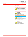
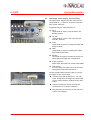
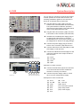
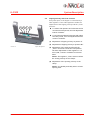
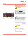
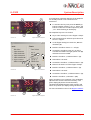
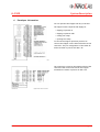
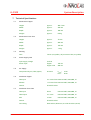
User’s Manual
InnoLas Flipper IL-F300
Instructions for
Operators, Service Personnel, and OEMs
Doc. Man IL-F300 Version 1.02/08-2008
©2008 InnoLas GmbH
InnoLas GmbH
Justus-von-Liebig-Ring 8
D-82152 Krailling / Germany
Tel.: ++49 (0)89 899 360 0
Fax.: ++49 (0)89 899 360 16
E-mail: [email protected]
Web: www.innolas.com
IL-F300
Table of Contents
Table of Contents
Flipper IL-F300
........................................... 1
1
How to use this manual . . . . . . . . . . . . . . . . . . . . . . . . . . . . . . . . . . 1
2
Safety Instructions . . . . . . . . . . . . . . . . . . . . . . . . . . . . . . . . . . . . . . 2
2.1
3
3
3
3
4
Shipment . . . . . . . . . . . . . . . . . . . . . . . . . . . . . . . . . . . . . . . . . 5
General Description . . . . . . . . . . . . . . . . . . . . . . . . . . . . . . . . . . 5
Installation . . . . . . . . . . . . . . . . . . . . . . . . . . . . . . . . . . . . . . . . . . . . 6
4.1
4.2
5
.
.
.
.
General . . . . . . . . . . . . . . . . . . . . . . . . . . . . . . . . . . . . . . . . . . . . . . 5
3.2
3.2
4
Warning Labels . . . . . . . . . . . . . . . . . . . . . . . . . . . . . . . . . . . .
Structure of warning labels . . . . . . . . . . . . . . . . . . . . . . . . . . . .
Symbol Definition . . . . . . . . . . . . . . . . . . . . . . . . . . . . . . . . . . .
Safety Instructions. . . . . . . . . . . . . . . . . . . . . . . . . . . . . . . . . . .
Flipper base . . . . . . . . . . . . . . . . . . . . . . . . . . . . . . . . . . . . . . . 6
CDA Supply, Power Supply, and Controlling . . . . . . . . . . . . . . . . . . . 7
Adjustments . . . . . . . . . . . . . . . . . . . . . . . . . . . . . . . . . . . . . . . . . . . 9
5.1
5.2
5.3
Wafer Size . . . . . . . . . . . . . . . . . . . . . . . . . . . . . . . . . . . . . . .
Flipping Velocity and Close Function . . . . . . . . . . . . . . . . . . . . . .
Wafer Recognition . . . . . . . . . . . . . . . . . . . . . . . . . . . . . . . . . .
Adjusting the Beam Spot Size and Display . . . . . . . . . . . . . . . . . . .
Manually Sensor Teaching via Two-Point Tuning . . . . . . . . . . . . . . .
Sensor Teaching via Software . . . . . . . . . . . . . . . . . . . . . . . . . . .
. 9
10
11
11
12
12
6
Developer Information . . . . . . . . . . . . . . . . . . . . . . . . . . . . . . . . . . 14
7
Technical Specifications . . . . . . . . . . . . . . . . . . . . . . . . . . . . . . . . . 15
7.1
7.2
7.3
7.4
7.5
7.6
7.7
Dimensions Flipper . . . . . . . . . . . .
Dimensions Festo CPX . . . . . . . . . .
Packing . . . . . . . . . . . . . . . . . . .
Power Supply CPX . . . . . . . . . . . . .
Air Supply . . . . . . . . . . . . . . . . . .
Interfaces Flipper . . . . . . . . . . . . .
Interfaces Festo CPX . . . . . . . . . . .
Doc. MAN IL-F300 Vers. 1.02
......................
......................
......................
......................
......................
......................
......................
©2008 InnoLas GmbH
15
15
15
15
15
15
15
Page I
IL-F300
System Description
Flipper IL-F300
1
How to use this manual
This manual provides all necessary information for
installing, commissioning, adjusting, and operating
the Flipper.
In certain cases the manual refers to third-party
manuals. These manuals are included in the scope
of delivery and it’s important to read these
manuals too.
Safety Instructions
First of all read the chapter 2 Safety Instructions
very carefully. This chapter provides all necessary
information to safeguard the operator and the
machine against any hazards. Every safety
instruction is repeated at the respective location in
the text.
Text and Pictures
The pictures in the left column complete the text
in the right column of the respective page.
Numbering
Points of interrest in a picture are referenced by a
number. The numbering starts with (1) at every
new page even if the picture is used more than
once in a chapter. You’ll find the description of the
numbered points of interrest in the text on the
same page referred by the respective number. So
the text and picture on one page have a very close
relation.
Instructions
Instructions that need a direct action by the
operator, the service personnel or any other
personnel are marked at the beginning by a
Subitems •
To make the description clearer the text uses
subitems that are marked by small bullets • at its
beginning.
Hyperlinks
The electronic version of the manual uses
hyperlinks that are marked blue, italic, and
underlined. If you click a hyperlink you can jump
to further information.To return to the previous
view click onto the jump destination. Even if not
marked the table of contents uses hyperlinks.
Doc. Man IL-F300 Vers. 1.02
©2008 InnoLas GmbH
Page 1
IL-F300
2
System Description
Safety Instructions
This product is manufactured in accordance with
state of the art technology and corresponds to
recognized safety regulations.
Nevertheless, there are dangers associated with
the use of the equipment even for its intended
purpose. Therefore:
Read this chapter carefully.
Always follow the operating instructions to
ensure proper operation of the systems.
Always follow the safety instructions to avoid
any accidents, trouble, or injuries.
The operation manual contains all necessary
information for the intended use of the InnoLas
Flipper and its relevant components as well as its
operation.
Only specially qualified personnel may operate or
maintain the InnoLas Flipper and its components to
avoid severe danger to the personnel or the
machine.
The following chapter describes the safety
instructions for the InnoLas Flipper. Both the
responsible personnel and every person that will
operate the machine directly or indirectly must
read and respect these safety instructions.
Neglecting the safety instructions may cause
severe injuries to personell or to the machine.
Doc. Man IL-F300 Vers. 1.02
©2008 InnoLas GmbH
Page 2
IL-F300
System Description
2.1
Warning Labels
Structure of warning labels
Pos
1
2
3
4
Danger!
Danger to life or system damage
Description
1
Warning sign (the sign varies, see „symbol
definition“ on page 2
2
Warning bars: thickness is according to the
warning level;
3
Warning heading:
Always turn off mains voltage and compressed air of the
system before installing the Flipper.
4
DANGER
indicates a hazardous situation which has a high probability of death or severe
injury
WARNING
indicates a hazardous situation which has some probability of death or severe
injury
CAUTION
indicates a hazardous situation which may result in
minor or moderate injury
NOTICE
indicates a statement of
company policy as the message relates directly or
indirectly to the safety of
personnel or protection of
property.
Warning text: describes the danger and how
to prevent it;
Symbol Definition
Warning
LASER Radiation
Danger/Notice
General operating Advice
Doc. Man IL-F300 Vers. 1.02
©2008 InnoLas GmbH
Page 3
IL-F300
System Description
Safety Instructions
Danger!
Danger to live or system damage
Always turn off mains voltage and compressed air of the
system before installing the Flipper.
Warning!
LASER Radiation
Class 2 LASER product. Do not stare into beam!
Notice!
System mal function
To avoid twisting the wafer take care that you adjust all
4 grub screws to exactly the same position.
Notice!
System mal function
Never try to adjust any of the other screws. Readjusting the wafer clamps is extremely difficult.
Doc. Man IL-F300 Vers. 1.02
©2008 InnoLas GmbH
Page 4
IL-F300
3
System Description
General
3.1
Shipment
The InnoLas ILF 300 Flipper system is shipped with
the Flipper base, the Flipper controller (Festo),
compressed air hoses, a 24-V-plug for the Festo
controller, and a connection cable with 2 Sub-D 25
connectors.
Pic. ILF 300 Bild 1
Depending on your order the Festo CPX terminal is
included or not.
ILF 300 1-01
Flipper Scope of Delivery
3.2
General Description
The Flipper ILF 300 is Edge Grip based (PEEK pins)
and is intended for flipping over 300 mm wafers
during the handling process.
Pic. ILF 300 Bild 14
The Flipper system consists of the Flipper station
itself and a controller. InnoLas systems use a Festo
CPX Terminal to control the Flipper.
The wafer recognition is done by a LASER sensor
that must be adjusted for the wafer reflection.
Homing of the Flipper to position 0° is always done
during initialization or directly before the Flipper
is loaded if necessary.
ILF 300 1-02
Flipper in Flipping Action
With InnoLas Sorters C3800 a wafer is only be
flipped at the beginning or at the end of a job. This
is valid for every operation mode. That means
flipping is only possible directly after a wafer was
carried from a cassette or directly before a wafer
is brought back to the cassette.
Pic. ILF 300 Bild 4
2
The Flipper locks the wafer by edge grip via 2 PEEK
pins at the lower clamp (1) and 2 PEEK pins at the
upper clamp (2) at both Flipper arms.
1
1
ILF 300 1-03
Doc. Man IL-F300 Vers. 1.02
With InnoLas Sorters C3800 the flipping operation
for a wafer processes always from position 0° to
position 180°.
2
Flipper Edge Grip
©2008 InnoLas GmbH
Page 5
IL-F300
4
System Description
Installation
Danger!
Danger to life or system damage
Always turn off mains voltage and compressed air of the
system before installing the Flipper.
4.1
Flipper base
(1) The Flipper base plate provides 3 holes for
fixing the Flipper on a mounting plate.
Pic. ILF 300 Bild 22
Use 3 Allen scews DIN 912 M8 x25 (or an
appropriate size for your mounting plate) to
fix the Flipper to the mounting plate. The
screws are not included in the scope of
delivery.
2
(2) The Flipper base plate provides 4 threads to
adjust the height above the mounting plate or
to adjust the pitch of the Flipper.
Use 4 grub screws (3 mm hex wrench) to
adjust the height or pitch of the Flipper.
1
Picture 1-05 shows the Flipper scale drawing with
all important measurements.
2
ILF 300 1-04
Flipper Mounting
Pic. ILF 300 Bild 2
2
1
2
ILF 300 1-05
Doc. Man IL-F300 Vers. 1.02
Flipper Scale Drawing
©2008 InnoLas GmbH
Page 6
IL-F300
System Description
4.2
1
CDA Supply, Power Supply, and Controlling
The Flipper base supports 4 Festo connectors for
compressed air, 1 connector for particle exhaust,
and 1 Sub-D connector.
2Pic.3 ILF
4 300 Bild 10
Compressed dry air (CDA) needs 6 bar.
6
5
7
(1) Set 0°
compressed air input to flip the wafer into
default position
(2) Set 180°
compressed air input to flip over the wafer
into 180° position
ILF 300 1-06
Flipper Interface
(3) Close
compressed air input for closing the clamp and
fixing the wafer
(4) Open
compressed air input for opening the clamp
and releasing the wafer
(5) Exhaust
connection for particle exhaust to protect the
wafer against damage and contamination
(6) D-Sub connector
digital input and output for sensors and LASER
(7) Hose fixings
to fix the hoses via cable ties for strain relief
and against unexpected movements
Use the included hoses and the cable to connect
the Flipper to the control unit.
Pic. ILF 300 Bild 10
ILF 300 1-07
Connect the 4 CDA sockets Set 0°, Set 180°,
Close, and Open to the respective compressed
dry air (CDA) controller sockets via the 4mm
hoses.
Flipper Connection
Connect the Exhaust socket via an 8 mm
vacuum hose to a particle exhauster.
Plug the Sub-D 25 connector to the Sub-D 25
socket of the Flipper.
Doc. Man IL-F300 Vers. 1.02
©2008 InnoLas GmbH
Page 7
IL-F300
System Description
You can use any controller to operate the Flipper.
InnoLas systems use a Festo CPX Terminal. The
following installation guide for the controller is
shown as an example using a Festo CPX.
Pic. ILF 300 Bild 13a
Plug the Ethernet cable (14) to the LAN
socket of the controller(Festo CPX Terminal).
The system Ethernet sends the operation
instructions for the Flipper. This could also be
done via the RS232 interface (15).
15
14
16
ILF 300 1-08
Festo CPX Terminal Front Side
Assemble the included power supply plug to
an appropriate cable (refer to the Festo
documentation for correct power rating). The
pin assignment is shown on the plug package.
Pic. ILF 300 Bild 21
(Red)
Connect the power supply plug to the 24 V
socket of the controller (13) and secure it.
(Brown)
View to plug
inside
Connect CDA socket of the CPX (10) to a 6 bar
CDA supply via a 8 mm hose.
Connect the CDA hoses from the Flipper to the
respective impulse valve output sockets of
the controller:
(Blue)
(Yellow-Green)
ILF 300 1-09
Power Supply Plug Assembly
9
1
3
5
7
11
Pic. ILF 300 Bild 17b
13
12
10
ILF 300 1-10
2
Plug the Sub-D 25 connector (16) to the SubD 25 socket of the controller (CPX Terminal).
4
6
8
Festo CPX Terminal Upper Side
(1):
(2):
(3):
(4):
Set 0°
Set 180°
Close
Open
Positions 5 to 8 are not used.
Connect the PFO socket (9) of the controller
via a 10 mm exhaust air hose outside the
machine or directly to a silencer.
Connect the power supply cable to a 24 V
direct current voltage power supply.
Description of valve connections
(1)
(2)
(3)
(4)
(5)
(6)
(7)
Doc. Man IL-F300 Vers. 1.02
©2008 InnoLas GmbH
Set 0°
Set 180°
Close
Open
Free
Free
Free
(8)
(9)
(10)
(11)
(12)
(13)
Free
PFO out
CDA in
PFO leave opened
Keep closed
Power supply
Page 8
IL-F300
5
System Description
Adjustments
5.1
Wafer Size
The Flipper is intended for use with wafers of a
diameter of 300 mm ± 2 mm.
Pic. ILF 300 Bild 20
1
The wafers should not be clamped tightly by the
clamp and the PEEK pins. Therefore the diameter
of the PEEK pins is not important.
The right Flipper clamp width (1) for the
respective wafer size is adjusted during assembly.
You can adjust this clamp width to the true wafer
size in small increments using the grub screws (2)
(2 mm hex wrench).
Notice!
System mal function
ILF 300 1-11
Flipper Gripper Width
Never try to adjust with any of the other screws.
Re-adjusting the wafer clamps is extremely difficult.
2
2 ILF 300 Bild 18a
Pic.
Fix the grub screws (2) with an Allen wrench
and loosen the lock nuts (3) with a screw
wrench.
Always loosen both lock nuts of a boom first
before you alter the grub screws.
3
2
ILF 300 1-12
Screw the grub screws (2)
clockwise to increase the clamp width or
counter clockwise to decrease the width.
Flipper Grub Screws
Notice!
System mal function
To avoid twisting the wafer take care that you adjust all
4 grub screws exactly in the same amount.
Ensure that all alignments of the grub screws are
equal. This means, e.g., if you alter one of the grub
screws a quarter turn clockwise you must also alter
the other grub screws a quarter turn clockwise.
To fix the positions of the grub screws hold
them with the Allen wrench and tighten the
lock nuts with the wrench.
Doc. Man IL-F300 Vers. 1.02
©2008 InnoLas GmbH
Page 9
IL-F300
System Description
5.2
Every CDA input of the Flipper is controlled by a
CDA regulator. These CDA regulators enable the
adjustment of the flipping velocity and the „Close“
function.
Pic. ILF 300 Bild 23
1
2
3
Flipping Velocity and Close Function
4
To reduce CDA pressure and velocities and to
increase the time period, turn the adjustment
button clockwise.
To increase the CDA and velocities and reduce
the time period, turn the adjustment button
counter clockwise.
(1) Adjustment of flipping velocity to positon 0°
(2) Adjustment of flipping velocity to positon 180°
ILF 300 1-13
Flipper CDA Regulators
(3) Adjustment of the time period untill the
„Close“ drives will reach their end position.
The base adjustment of this regulator is 1.5
turns (540°) counter clockwise from closed
state.
Notice: The regulator „Close“ does not affect
the closing velocity of the clamps.
(4) Adjustment of the opening velocity of the
clamp.
Notice: You should preferably select a slower
opening time.
Doc. Man IL-F300 Vers. 1.02
©2008 InnoLas GmbH
Page 10
IL-F300
System Description
5.3
Pic. ILF 300 Bild 12a
ILF 300 1-14
5
8
7
Flipper LASER Sensor
Wafer Recognition
Wafers are detected via a LASER sensor. A LASER
diode (5) transmits a LASER beam (6) via a focusing
lens to the wafer. The wafer reflects the beam to
the photo receiver (7). The amplifier (8) analyzes
the signal for its light intensity.
Regardless of your target distance, you can adjust
the beam spot to meet your application needs.
Adjusting the Beam Spot Size and Display
Pic. ILF 300 Bild 19
Warning!
LASER Radiation
6
Class 2 LASER product. Do not stare into beam!
1
Remove the cover plate (1). It’s fixed by 2
screws.
Take care the LASER is on. Verify this by
holding a piece of white paper into the beam.
ILF 300 1-15
Flipper Wafer Detection
Lay a wafer exactly on to the Flipper clamps.
Turn the focus ring of the transmitter. Look
for intensity value of about 5000 or lower at
the upper red amplifier display (2).
Pic. ILF 300 Bild 24
After completing the adjustment fix the focus
ring by turning the focus lock screw vertically.
Re-attach the cover plate.
2
5
Adjusting the sensor to detect in a distance range
of 50 mm the spot diameter is about 0.3 mm.
Adjusting the sensor to detect in a distance range
of 300 mm the spot diameter is about 0.8 mm.
ILF 300 1-16
3
Flipper LASER Sensor
4
(4) The red LED A (on) indicate that the
automatically calculated threshold between
wafer present and wafer not present was
exceeded. This means wafer is present.
2
Pic. ILF 300 Bild 15
ILF 300 1-17
5
Doc. Man IL-F300 Vers. 1.02
(3) The green LED (on) indicates an active LASER.
(5) The green display shows the automatically
calculated threshold between wafer present
and wafer not present and is dark during
threshold calculation.
Flipper LASER Sensor Amplifier
For more information refer to the Keyence manual.
©2008 InnoLas GmbH
Page 11
IL-F300
System Description
Manual Sensor Teaching via Two-Point Tuning
Warning!
LASER Radiation
Class 2 LASER product. Do not stare into beam!
You must teach the sensor for wafer recognition.
Take care that the beam spot size is already
adjusted and no wafer is on the Flipper.
2
4
1
Pic. ILF 300 Bild 15
Maybe you must de-activate the key lock first.
To de-activate the key lock press the MODE
(1) button together with the „up“ or „down“
(3) button for about 3 seconds respectively
until „un L“ starts flashing in the display to
deactivate the key lock.
Push the SET button (4) untill you get a steady
display.
5
ILF 300 1-18
Lay a wafer exactly on to the Flipper clamps.
3
Flipper LASER Sensor Amplifier
Push the SET button (4) again untill you get
steady display.
Sensor teaching is now complete.The red display
(2) shows the current reflection intensity. The
green display (5) shows the automatically
calculated threshold between wafer present and
wafer not present (no display during calculation).
For more information refer to the Keyence manual.
Sensor Teaching via Software
Warning!
LASER Radiation
Class 2 LASER product. Do not stare into beam!
With InnoLas Sorter C3800 systems service
personnel can teach the wafer recognition for the
sensor via software. Take care that the beam spot
size is already adjusted.
To teach the sensor via software the key lock of the
amplifier must first be activated.
Doc. Man IL-F300 Vers. 1.02
©2008 InnoLas GmbH
Page 12
IL-F300
System Description
2
In normal sorter operation the keys of the amplifier
are already locked. If not follow the next
instruction.
1
To activate the key lock press the MODE (1)
button together with the „up“ or „down“ (3)
button for about 3 seconds respectively until
„Loc“ starts flashing in the display.
Pic. ILF 300 Bild 15
The amplifier keys are now locked.
5
3
ILF 300 1-19
Lay a wafer exactly on to the Flipper clamps.
Flipper LASER Sensor Amplifier
In the InnoLas Sorter software open the menu
Service / Flipper.
In the Flipper dialog box mark the „Manual“
checkbox (4).
Pic. ILF 300 Bild 26
Mark the checkbox Sensor on / off (6).
6
2
8
5
Unmark the checkbox Laser off /on (7) to
activate the LASER. The light yellow icon (8)
indicates an active LASER.
Mark the checkbox „Calibrate Sensor“ (9).
Wait about 3 seconds.
Unmark the checkbox „Calibrate Sensor“ (9).
7
9
Remove the wafer from the Flipper clamps.
10
ILF 300 1-20
4
Mark the checkbox „Calibrate Sensor“ (9).
Flipper Sensor Calibration
Wait about 3 seconds.
Unmark the checkbox „Calibrate Sensor“ (9).
2
1
Mark the checkbox „Automatic“ (10).
Sensor teaching is now complete. The red display
(2) shows the current reflection intensity. The
green display (5) shows the automatically
calculated threshold between wafer present and
wafer not present (no display during calculation).
Pic. ILF 300 Bild 15
For more information refer to the Keyence manual.
5
ILF 300 1-19
Doc. Man IL-F300 Vers. 1.02
3
Flipper LASER Sensor Amplifier
©2008 InnoLas GmbH
Page 13
IL-F300
6
System Description
Developer Information
You can operate the Flipper with any controller.
The Flipper needs a separat CDA supply for
Pic. ILF 300 Bild 22
• flipping to position 0°
• flipping to position 180°
• closing the clamp
• opening the clamp
To control the Flipper operation you have to
connect the Flipper via the Sub-D 25 socket to the
controller. The pin configuration of the Sub-D 25
socket is shown in picture ILF 300 1-22.
ILF 300 1-22
Flipper D-Sub Connector
The connection circuit for the impulse valves of the
controller that control the CDA for the Flipper
movements is shown in picture ILF 300 1-23.
Pic. ILF 300 Bild 28
ILF 300 1-23
Doc. Man IL-F300 Vers. 1.02
Flipper Sensor Valve Connection
©2008 InnoLas GmbH
Page 14
IL-F300
7
System Description
Technical Specifications
7.1
7.2
7.3
Dimensions Flipper
Height:
approx.
382.5 mm
Width:
approx.
435 mm
Depth:
approx.
180 mm
Weight:
approx.
8.9 kg
Height:
approx.
75 mm
Width:
approx.
260 mm
Depth:
approx.
125 mm
Weight:
approx.
1.6 kg
Dimensions Festo CPX
Packing
Case
7.4
7.5
Carton (recycable), PE protection film (recycable)
Power Supply CPX
Input supply voltage
24 V DC
Power input
Flipper
Flipper+CPX
155 mA
290 mA
Pressure
Pnorm:
Pmax:
Air Supply
Compressed dry air (CDA) (input)
7.6
7.7
6 bar
8 bar
Interfaces Flipper
CDA input
4 x 4 mm Festo material: PBT, POM,NBR, SS
Exhaust
1 x 8 mm Festo material: PBT, POM,NBR, SS
Sensors
D-Sub 25 socket
Interfaces Festo CPX
CDA input
8 mm
material: PBT, POM,NBR, SS
CDA output
4 x 4 mm
material: PBT, POM,NBR, SS
PFO
10 mm
material: PBT, POM,NBR, SS
Sensors
D-Sub 25 socket
Controlling
RJ45 socket (Ethernet) or D-Sub 9 socket (serial)
Doc. Man IL-F300 Vers. 1.02
©2008 InnoLas GmbH
Page 15