1
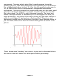
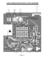
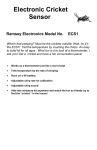
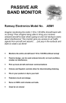
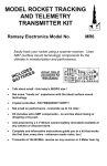
LED Strobe Light Ramsey Electronics Model No. LEDS1 Super-Bright LEDs pulse to your music. Switch over to stroboscope mode for a super-blue hypnotic flash! Use the LEDs as a super flashlight. The possibilities are endless! • Bright blue stroboscope without high voltage or glass tubes. • Adjustable flash rate. • Audio mode flashes to your stereo. • Runs on 12V DC. • LEDs won’t burn out. • External trig allows for expandability. • 3 different LED boards to choose from. LEDS1• 1 PARTIAL LIST OF AVAILABLE KITS: RAMSEY TRANSMITTER KITS • FM10A, FM25B FM Stereo Transmitters • AM1, AM25 Transmitter RAMSEY RECEIVER KITS • FR1 FM Broadcast Receiver • AR1 Aircraft Band Receiver • SR2 Shortwave Receiver • AA7 Active Antenna • SC1 Shortwave Converter RAMSEY HOBBY KITS • SG7 Personal Speed Radar • SS70A Speech Scrambler/Descrambler • TT1 Telephone Recorder • SP1 Speakerphone • MD3 Microwave Motion Detector • PH14 Peak hold Meter • AVS10 Automatic Sequential Video Switcher • WCT20 Cable Wizard Cable Tracer • LABC1 Lead Acid Battery Charger • ECG1 Heart Monitor • DCI1 DTMF Controller Interface RAMSEY AMATEUR RADIO KITS • HR Series HF All Mode Receivers • QRP Series HF CW Transmitters • CW7 CW Keyer • QRP Power Amplifiers RAMSEY MINI-KITS Many other kits are available for hobby, school, scouts and just plain FUN. New kits are always under development. Write or call for our free Ramsey catalog. LEDS1 LED Strobe Ramsey Electronics publication No. LEDS1 Rev. 1.2 April 2003 COPYRIGHT ©2003 by Ramsey Electronics, Inc. 590 Fishers Station Drive, Victor, New York 14564. All rights reserved. No portion of this publication may be copied or duplicated without the written permission of Ramsey Electronics, Inc. Printed in the United States of America. LEDS1• 2 Ramsey Publication No. LEDS1 Manual Price Only $5.00 KIT ASSEMBLY AND INSTRUCTION MANUAL FOR LED Strobe Light TABLE OF CONTENTS Introduction ........................................................ 4 LEDS1 Circuit Description ................................. 4 “Learn-As-You-Build” Kit Assembly ....................6 Parts List............................................................ 7 Assembly Steps ..................................................9 Setup and Testing ...........................................12 Troubleshooting Guide .....................................13 Main Board Parts Layout Diagram ...................16 Main Board Schematic Diagram .......................17 LED Board Parts Layout Diagram ....................18 LED Board Schematic Diagram........................19 Ramsey Kit Warranty........................................23 RAMSEY ELECTRONICS, INC. 590 Fishers Station Drive Victor, New York 14564 Phone (585) 924-4560 Fax (585) 924-4555 www.ramseykits.com LEDS1• 3 WARNING: According to the Epilepsy Foundation it is possible that this kit may present a risk to those with this affliction. Affected individuals must be aware of the possible triggering of seizures by certain visual stimuli. INTRODUCTION Everyone has seen a strobe light at one time or another. The bright eye-popping lights are real attention-getters. They typically use Xenon bulbs which require high-voltage. In recent years, super bright LEDs have become cheaper and brighter, to the point where they rival flashlight bulbs. Now, using some of these LEDs, we bring you the LEDS1! The LEDs take the place of a Xenon flash bulb. You get a nice bright blue flash without high voltage, and no glass tube to break. Included with your kit is a 9 LED array, but a 20 LED array is also available from Ramsey. In addition, the LEDs will last virtually forever instead of burning out after a short time like a tube. As well as flashing at an adjustable rate like traditional strobe lights, the LEDS1 also has an audio input that allows it to flash to music. Both high and low pass filters allow the LEDS1 to flash to treble or bass. And for even more expandability, there is an external trigger jack that allows you to control the LEDS1 with your own external source or connect two LEDS1’s together. LEDS1 CIRCUIT DESCRIPTION Before we begin dissecting the circuit, let’s have a look at the “big picture” and see what it is that we’re trying to accomplish. What we want is to have a circuit that will flash a bunch of super bright LEDs at an adjustable frequency, and also be able to flash them in response to an audio input. The adjustable frequency is generated by U3, LM555 timer IC. The potentiometer R19 controls the frequency at which U3 oscillates. The pulses from U3 are fed to Q1, a power MOSFET. This MOSFET switches all the LEDs on whatever LED board is plugged in to jack J5. A power MOSFET is used because it makes a good high-current switch and won’t get hot. That’s right, the LEDs are drawing enough power that heat is a design concern! To make the LEDS1 flash to music is a bit more complicated. The first step is to run the audio through a filter depending on whether you want the LEDS1 to flash to bass or treble. There are two user selectable filters to do this: high pass and low pass. The high pass filter will filter out low frequency signals and allow high frequency signals (treble) to get through. The low-pass filter attenuates high frequencies and lets low frequencies (bass) through. The high-pass filter is made up of U1:A and its support components. The low pass filter is made up of U1:C and its support LEDS1• 4 components. The user selects which filter the audio passes through by pushing switch S1. After being filtered the audio signal arrives at U1:B where it is amplified slightly by a factor of 22. After this, the amplified audio goes to U2, an NE555 timer, that is configured as a retriggerable monostable multivibrator. The circuit produces an output pulse every time the audio signal gets above its threshold level. For example, consider a piece of music that has a drum beat. The LEDS1 is set to low-pass the audio. The drum beat makes it through the filter, is amplified by U1:B, and triggers U2. Now, you might be thinking: “Isn’t sound a sine wave? Every time the audio reaches a peak, it would trigger U2 and produce a flashing effect” This is true, and sometimes a single drum hit will produce a couple of quick flashes instead of just one flash, because one drum hit contains many peaks as shown in the picture. This is where some “tweaking” can come in to play, and is discussed later in the manual. Now let’s take a look at the parts list and get building! LEDS1• 5 RAMSEY Learn-As-You-Build KIT ASSEMBLY There are numerous solder connections on the LEDS1 printed circuit board. Therefore, PLEASE take us seriously when we say that good soldering is essential to the proper operation of your kit. • • • • Use a 25-watt soldering pencil with a clean, sharp tip. Use only rosin-core solder intended for electronics use. Use bright lighting, a magnifying lamp or bench-style magnifier may be helpful. Do your work in stages, taking breaks to check your work. Carefully brush away wire cuttings so they don't lodge between solder connections. We have a two-fold "strategy" for the order of the following kit assembly steps. First, we install parts in physical relationship to each other, so there's minimal chance of inserting wires into wrong holes. Second, whenever possible, we install in an order that fits our "Learn-As-You Build" Kit building philosophy. This entails describing the circuit that you are building instead of just blindly installing components. We hope that this will not only make assembly of our kits easier, but help you to understand the circuit you’re constructing. For each part, our word "Install" always means these steps: 1. Pick the correct part value to start with. 2. Insert it into the correct PC board location. 3. Orient it correctly, follow the PC board drawing and the written directions for all parts - especially when there's a right way and a wrong way to solder it in. (Diode bands, electrolytic capacitor polarity, transistor shapes, dotted or notched ends of IC's, and so forth.) 4. Solder all connections unless directed otherwise. Use enough heat and solder flow for clean, shiny, completed connections. LEDS1• 6 LEDS1 MAIN BOARD PARTS LIST The main board is the larger of the two. Sort and “check off” the components in the boxes provided. We do our best to pack all our kits correctly but it is possible that a mistake has occurred and we missed a part. Please note that physical descriptions of parts are for those currently being shipped. Sometimes the parts in your kit may have a different appearance but still have the same values. RESISTORS 3 1K ohm resistor [brown-black-red] (R5,R6,R8) 5 10K ohm resistor [brown-black-orange] (R1,R2,R3,R4,R10) 1 22K ohm resistor [red-red-orange] (R9) 4 68 ohm resistor [blue-gray-black] (R12,R13,R14,R15) 2 100K ohm resistor [brown-black-yellow] (R17,R20) 2 300 ohm resistor [orange-black-brown] (R7,R16) 1 330 ohm resistor [orange-orange-brown] (R18) 1 470K resistor [yellow-violet-yellow] (R11) 1 100K potentiometer (R19) CAPACITORS 4 .1 uF ceramic disc capacitors [marked 104] (C1,C2,C13,C14) 1 .1 uF electrolytic capacitor (C7) 4 .001 uF ceramic disc capacitor [marked 102] (C3,C4,C5,C6) 1 .47 uF electrolytic capacitor (C9) 2 1 uF electrolytic capacitor (C8,C11) 1 10 uF electrolytic capacitor (C12) 1 33 uF electrolytic capacitor (C10) SEMICONDUCTORS Note: Chips may have other numbers and letters on them; the important numbers are those listed in brackets. 2 1 2 1 1 1 NE555 timer [marked NE555] (U2,U3) 71F7034_H N channel power MOSFET [marked 71F7034_H] (Q1) 1N4002 silicon diode (D10,D11) 1N270 germanium diode (D12) LM324 quad op-amp [marked LM324N] (U1) 7805 voltage regulator [marked 7805] (VR1) MISCELLANEOUS 2 2 2.1mm power jack (J2,J5) 2.1mm power plugs LEDS1• 7 1 1 1 3 1 24AWG wire, red/black, 7 inches 3.5mm stereo jack (J3) RCA jack (J1) pushbutton switches (S1,S2,S3) double sticky foam tape 4 inches LEDS1 LED BOARD PARTS LIST The LED board is the smaller of the two. RESISTORS 4 1 68 ohm resistor [blue-gray-black] (R31,R32,R33,R34) 150 ohm resistor [brown-green-brown] (R35) SEMICONDUCTORS 9 Vishay Telux™ LEDs (D28,D33,D35,D36,D37,D38,D39,D40,D41) MISCELLANEOUS 1 2.1mm power jack (J6) LEDS1• 8 LEDS1 PC BOARD ASSEMBLY STEPS 1. Let’s begin with all the jacks at the bottom of the board. Install J2, the power jack in the lower right hand corner. 2. Install R6, 1K ohm resistor [brown-black-red], under R5. 3. Install J5, another power jack next to J2. This is the jack that connects to the LED board. 4. Now, let’s start soldering in some real components. Start with R17, 100K ohm resistor [brown-black-yellow] in between J5 and J2. This is the audio input jack. 5. Install RCA jack, J1. 6. Install J3, 3.5mm stereo jack, next to J5. This jack is for external triggering and connecting two LEDS1’s together. 7. Install R20, 100K ohm resistor [brown-black-yellow] next to J1. 8. Install C14, .1 uF ceramic disk capacitor [marked 104], next to R20. 9. Install C13, .1 uF ceramic disk capacitor [marked 104], next to C14. 10. Install R2, 10K ohm resistor [brown-black-orange], next to C13. 11. Install R1, 10K ohm resistor [brown-black-orange], above C13. 12. Install U1, LM324 [marked LM324N] above R1. Make sure the notch at one end of the IC lines up with the notch on the board drawing. 13. Install R9, 22K ohm resistor [red-red-orange], at the right end of U1. 14. Install C5, .001 uF capacitor [marked 102] next to R9. 15. Install R3, 10K ohm resistor [brown-black-orange] next to C5. 16. Install C4, .001 uF ceramic disk capacitor [marked 102], under R3. 17. Install C3, .001 uF ceramic disk capacitor [marked 102], under C4. 18. Install R13, 68 ohm resistor [blue-gray-black]. 19. Install R12, 68 ohm resistor [blue-gray-black]. 20. Install C6, .001 uF ceramic disk capacitor [marked 102], next to R3. 21. Install R14, 68 ohm resistor [blue-gray-black], to the right of C6. 22. Install VR1, 7805 5V regulator. This powers the ICs on the board. The writing on the regulator faces D11. LEDS1• 9 23. Install C9, .47 uF electrolytic capacitor under VR1. Watch the polarity. Make sure the band on the cap lines up with the right hole on the board. Only “+” is marked on the board, the band on the cap could be “+” or “-”. 24. Install R5, 1K ohm resistor [brown-black-red], next to C9. 25. Install C11, 1 uF electrolytic capacitor, next to R5. Watch polarity. 26. Install C12, 10 uF electrolytic capacitor just above C11. Watch polarity again. 27. Install U3, NE555 timer IC, to the left of C12. Line up the notch at on end with the notch on the board drawing. U3 is the oscillator that flashes the LEDs in stroboscope mode. 28. Install D11, 1N4002 silicon diode, to the left of U3. Make sure the band at one end of the diode lines up with the band on the board drawing. 29. Install C10, 33 uF electrolytic capacitor above D11. Watch that polarity. 30. Install D10, the other 1N4002, above U3. Line up the band again. 31. Install R18, 330 ohm resistor [orange-orange-brown] next to D10. 32. Install R10, 10K ohm resistor [brown-black-orange], just above D10. 33. Install U2, the other NE555 timer IC, next to R10. U2 flashes the LEDs in audio mode. 34. Install R11, 470K ohm resistor [yellow-violet-yellow], next to U2. 35. Install C7 .1 uF capacitor next to R11. You’ll see that the PC board layout shows the outline of an electrolytic capacitor but that we’ve supplied a disc cap. You’ll have to bend the leads with so that they fit into the smaller spacing; ignore the polarity markings since disc caps are not polarity sensitive. It looks tight but it can be done! Solder as usual. 36. Install C8, 1 uF electrolytic capacitor. Follow the silkscreen layout for orientation. 37. Install R15, 68 ohm resistor [blue-gray-black], up and to the left of U2. 38. Install R19, 100K ohm potentiometer up at the top of the board. This controls the flash rate in stroboscope mode. 39. Install R7 and R16, both 300 ohm resistors [orange-black-brown], at the top of the board. 40. Install S1, S2, and S3, pushbutton switches, at the top of the board. 41. Install Q1, 71F7034_H N channel MOSFET, in the middle left of the LEDS1• 10 board. Put Q1 in its three holes, then bend it back so that it lays flat on the board. Make sure that no metal on Q1 touches the ground plane of the circuit board, only the rectangle directly behind it that acts as its heatsink. 42. Install R8, 1K ohm resistor [brown-black-red], to the right of Q1. 43. Install D12, 1N270, germanium diode under Q1. Line up the cathode band again. 44. Install C2, .1 uF capacitor [marked 104], under D12. 45. Install C1, .1 uF capacitor [marked 104], next to C1. 46. Install R4, 10K ohm resistor [brown-black-orange], down and to the right of Q1. Now, you’re all done with the main board! You only need to solder the LEDs onto the LED board and you will be ready to start strobing! 47. Install all the LEDs, look at the circuit board drawing to make sure they go in the right way. These are 4 lead components and will be hard to unsolder without destroying the board. There is a flat spot on the LEDs that indicates which two pins are negative. Be sure the flat spot on the drawing lines up with the flat spot on the board drawing. You may have wondered why there are places for LEDs on the main board. This is for you, the experimenter, to play around with. If you solder in your own LEDs into these locations, they will flash along with the LED board. Be sure that the LEDs can take 50ma of current if you aren’t using Telux LEDs. 48. Install R35, 150 ohm resistor [brown-green-brown]. It is a large resistor so you’ll have to mount it standing up. LEDS1• 11 49. Install R31, R32, R33, and R34, 68 ohm resistors [blue-gray-black]. 50. Install the 2.1mm power jack (J6). 51. You now need to solder up the cable that connects the LED board to the main board. Strip the ends off of the twisted red and back wire. Unscrew the caps from the power plugs and slide them onto the wire. Now solder the red wires onto the center pins and the black wires onto the side pins. Screw the end caps back on. Now it’s stroboscope time! SETUP AND TESTING Plug the cable you just made into the LED board and J5 on the main board. Plug in a 12V DC center “+” adapter into J2 on the main board. If you bought the matching case for your LEDS1, attach the LED board to the top of the case with some double sticky foam tape. Push S3 to turn on the unit. Now, for stroboscope mode, make sure S2 is in the out position. The LEDs should be flashing. If you turn the pot you can vary the flash rate. To have some fun with the stroboscope mode, find something that spins to do some “stop motion”. A fan can work, depending on how fast it’s spinning. A toy top also makes a good test subject. When you have your spinning test subject going, point your flashing LEDS1 at it and adjust the strobe rate until it appears to “freeze” in time. The effect can be quite striking. The strobe rate will have to be different depending on how fast your test object is spinning. If you’re using a top, you’ll notice that as it slows down, you will have to readjust your LEDS1 to compensate. Another cool thing to try is to go into a dark room and start your LEDS1 flashing. Now move around in front of it, or have a friend do it. You now have your own mini disco! Let’s test out the audio mode. Connect the RCA jack to a line level audio source like a stereo. Push in switch S2 to set the LEDS1 to audio mode. Now set switch S1 to set the filter. When the switch is in, the high pass filter is selected, when it is out, the low-pass filter is selected. High pass is for treble, low pass is for bass. On the low-pass setting the lights should LEDS1• 12 flash to the beat if you are playing a song that has a good drum beat. If there is a lot of electric guitar you will probably see multiple flashes with each guitar hit because an electric guitar will tend to produce a more continuous string of low frequencies as opposed to the quick “thump” of a drum. On the high-pass setting the LEDS1 will tend to trigger on things like a symbol hit or snare drum beat. Instruments like these tend to produce a lot of high frequencies. Experiment around and try different types of music to see how the LEDS1 responds. TROUBLESHOOTING GUIDE If your LEDS1 doesn’t work right away don’t worry; it’s probably something simple. The first thing is to make sure of is that the LM324 and 2 NE555’s are oriented correctly. Inserting ICs backwards is a no-no. If you’ve done it, just carefully unsolder them and solder them in the right way. They probably survived. The NE555 is pretty tough, and I’ve never seen anyone break an LM324. If the ICs are ok take a look at the diodes and electrolytic caps. These have a polarity and if put in wrong they won’t work right. GOING FURTHER: This section of the manual is for our customers who are really into messing around with their kit. It is for those of you who will never be satisfied until you see how much you can tweak your kit until it breaks, at which point, incidentally, it would be our honor to sell you another one. THAT BIG OL’ BLUE FLASHLIGHT When building this kit you may have noticed that the power jack on the LED board is the same as the jack the power adapter plugs into. You were probably tempted to plug the adapter directly into the LED board. Well, go ahead! You will get a blinding blue flashlight, even more so with the Ramsey LEDS1-LG 20 LED board! You might want to keep an eye on the board if you’re using it that way though, since the LEDs can get rather warm and you wouldn’t want to burn them out. Also, it’s better to use a wall adapter than a big power supply unless you’re going to current limit the output. These LEDs will draw quite a bit of current so either put a large enough resistor inline to limit it or simply turn up the current limit on your supply. LEDS1• 13 MORE LEDS! If 9 LEDs isn’t enough you can purchase a 20 LED array, the LEDS1-LG, from Ramsey Electronics. This plugs into your kit the same way as the 9 LED board. We also sell an LED stick that works a little differently. It uses a 3.5mm stereo phono jack instead of a power plug type jack. The stereo jack plugs into jack J3 on the LEDS1 main board. To do this you need to solder up a cable like you did earlier for the 9 LED board that came with the LEDS1. The only difference is that this time you will solder together 2 stereo plugs that have 3 pins instead of 2. These come with the LEDS1-ST stick kit. AUDIO RESPONSE TWEAK Sometimes when using the LEDS1 in audio mode with the low-pass filter selected, the lights will flash several times to what sounds like a single beat. If this is annoying, the gain on the amplifier made with U1:B can be lowered to present less audio peaks to U2, which triggers the LEDs. This means U2 will trigger less often and there will be fewer flashes for a given sound. To lower the gain on U1:B, just put a smaller resistor in place of R9. You can even use a potentiometer. If the gain gets too low, the LEDs won’t flash at all. Experiment to find the value that gives you the effect you want. EXTERNAL TRIGGERING You can trigger the LEDS1 to flash from an external source. This is done by plugging a 5V DC to 12V DC voltage or pulse into Jack J3. Jack J3 is a 3.5mm stereo phono jack. To connect an external source, you need to buy or make a double ended cable, each end having a 3.5mm stereo plug. Observe the pinout shown in the picture. The Ramsey LEDS1ST kit comes with these. LEDS1• 14 2 LEDS1s CHAINED TOGETHER For even more flashing power you can buy 2 LEDS1s and make them flash at the same time either in audio or stroboscope mode. The two kits are connected via the external trigger jack. Connect them with the same double ended 3.5mm cable described above. One LEDS1 is the “master” that drives the other LEDS1, or the “slave”. Set the master to stroboscope or audio mode and the slave to audio mode. The slave will now flash synchronously with the master. The slave will also draw power from the master and run without a power adapter of its own. This does load the master’s power adapter quite a bit, and using two adapters is recommended for long term use. CONCLUSION We sincerely hope that you will enjoy the use of this Ramsey product. As always, we have tried to compose our manual in the easiest, most “user friendly” format that is possible. As our customers, we value your opinions, comments, and additions that you would like to see in future publications. Please submit comments or ideas to: Ramsey Electronics Inc. Attn. Hobby Kit Department 590 Fishers Station Drive Victor, NY 14564 or email us at: [email protected] And once again, thanks from the folks at Ramsey! LEDS1• 15 LEDS1 MAIN BOARD PARTS LAYOUT DIAGRAM LEDS1• 16 LEDS1• 17 LEDS1-SM 9 LED BOARD LAYOUT LEDS1• 18 LEDS1• 19 LEDS1• 20 LEDS1• 21 LEDS1• 22 The Ramsey Kit Warranty Please read carefully BEFORE calling or writing in about your kit. Most problems can be solved without contacting the factory. Notice that this is not a "fine print" warranty. We want you to understand your rights and ours too! All Ramsey kits will work if assembled properly. The very fact that your kit includes this new manual is your assurance that a team of knowledgeable people have field-tested several "copies" of this kit straight from the Ramsey Inventory. If you need help, please read through your manual carefully, all information required to properly build and test your kit is contained within the pages! However, customer satisfaction is our goal, so in the event that you do have a problem, take note of the following. 1. DEFECTIVE PARTS: It's always easy to blame a part for a problem in your kit, Before you conclude that a part may be bad, thoroughly check your work. Today's semiconductors and passive components have reached incredibly high reliability levels, and its sad to say that our human construction skills have not! But on rare occasions a sour component can slip through. All our kit parts carry the Ramsey Electronics Warranty that they are free from defects for a full ninety (90) days from the date of purchase. Defective parts will be replaced promptly at our expense. If you suspect any part to be defective, please mail it to our factory for testing and replacement. Please send only the defective part (s), not the entire kit. The part(s) MUST be returned to us in suitable condition for testing. Please be aware that testing can usually determine if the part was truly defective or damaged by assembly or usage. Don't be afraid of telling us that you 'blew-it', we're all human and in most cases, replacement parts are very reasonably priced. 2. MISSING PARTS: Before assuming a part value is incorrect, check the parts listing carefully to see if it is a critical value such as a specific coil or IC, or whether a RANGE of values is suitable (such as "100 to 500 uF"). Often times, common sense will solve a mysterious missing part problem. If you're missing five 10K ohm resistors and received five extra 1K resistors, you can pretty much be assured that the '1K ohm' resistors are actually the 'missing' 10 K parts ("Hum-m-m, I guess the 'red' band really does look orange!") Ramsey Electronics project kits are packed with pride in the USA. If you believe we packed an incorrect part or omitted a part clearly indicated in your assembly manual as supplied with the basic kit by Ramsey, please write or call us with information on the part you need and proof of kit purchase. 3. FACTORY REPAIR OF ASSEMBLED KITS: To qualify for Ramsey Electronics factory repair, kits MUST: 1. NOT be assembled with acid core solder or flux. 2. NOT be modified in any manner. 3. BE returned in fully-assembled form, not partially assembled. 4. BE accompanied by the proper repair fee. No repair will be undertaken until we have received the MINIMUM repair fee (1/2 hour labor) of $25.00, or authorization to charge it to your credit card account. 5. INCLUDE a description of the problem and legible return address. DO NOT send a separate letter; include all correspondence with the unit. Please do not include your own hardware such as nonRamsey cabinets, knobs, cables, external battery packs and the like. Ramsey Electronics, Inc., reserves the right to refuse repair on ANY item in which we find excessive problems or damage due to construction methods. To assist customers in such situations, Ramsey Electronics, Inc., reserves the right to solve their needs on a case-by-case basis. The repair is $50.00 per hour, regardless of the cost of the kit. Please understand that our technicians are not volunteers and that set-up, testing, diagnosis, repair and repacking and paperwork can take nearly an hour of paid employee time on even a simple kit. Of course, if we find that a part was defective in manufacture, there will be no charge to repair your kit (But please realize that our technicians know the difference between a defective part and parts burned out or damaged through improper use or assembly). 4. REFUNDS: You are given ten (10) days to examine our products. If you are not satisfied, you may return your unassembled kit with all the parts and instructions and proof of purchase to the factory for a full refund. The return package should be packed securely. Insurance is recommended. Please do not cause needless delays, read all information carefully. LEDS1• 23 LEDS1 LED STROBE LIGHT Quick Reference Page Guide Introduction to the LEDS1 ................................. 4 LEDS1 Circuit Description ................................ 4 Parts List ........................................................... 7 Parts Layout Diagrams ............................... 12,14 Schematic Diagram..................................... 13,15 Troubleshooting Guide ..................................... 17 Ramsey Kit Warranty ....................................... 23 REQUIRED TOOLS • Soldering Iron Ramsey WLC100 • Thin Rosin Core Solder Ramsey RTS12 • Needle Nose Pliers Ramsey MPP4 or RTS05 • Small Diagonal Cutters Ramsey RTS04 <OR> Technician’s Tool Kit TK405 ADDITIONAL SUGGESTED ITEMS • Holder for PC Board/Parts Ramsey HH3 • Desoldering Braid Ramsey RTS08 Manual Price Only: $5.00 •Ramsey Digital MultimeterNo. Ramsey M133 Publication MSCN-1 Assembly and Instruction manual for: RAMSEY MODEL NO. SCN-1 800 - 950 MHz SCANNER CONVERTER KIT RAMSEY ELECTRONICS, INC. 590 Fishers Station Drive Victor, New York 14564 Phone (585) 924-4560 Fax (585) 924-4555 LEDS1• 24 www.ramseykits.com TOTAL SOLDER POINTS 187 ESTIMATED ASSEMBLY TIME Beginner .............. 3 hrs Intermediate ........ 2 hrs Advanced ............. 1 hrs