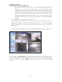
1
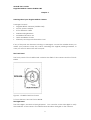
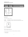
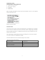
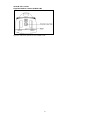
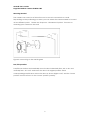
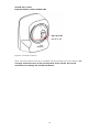
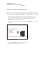
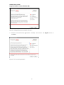
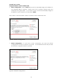
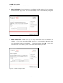
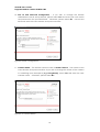
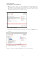
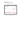
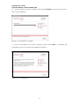
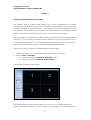
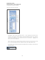
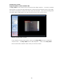
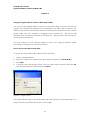
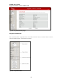
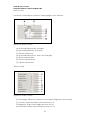
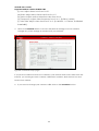
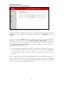
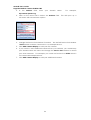
Asoka® User’s Guide PlugLink® 9850 IP Camera PL9850-CMS User’s Guide PlugLink 9850 IP Camera PL9850-CMS © 2007 Asoka USA Corporation. Asoka, PlugLink and the Asoka logo are registered trademarks or trademarks of Asoka USA Corporation. Information is subject to change without notice. All rights reserved. PL9850-CMS 041907 PN: 66-0316-010 1 Asoka® User’s Guide PlugLink® 9850 IP Camera PL9850-CMS Table of Contents Chapter Title Page 1 Introduction 3 2 Important Safety Information 4 3 Learning About your PlugLink IP Camera 5 4 Connecting the PlugLink 9850 for Setup 11 5 Installing and Configuring the PlugLink IP Camera 12 6 Placement Options 20 7 Using the PlugLink 9850 IP Camera Utility 21 8 Using the PlugLink 9850 Web based Utility 27 9 Configuring the PlugLink 9850 for Remote Access 32 10 Technical Support Information 35 11 Glossary 36 12 Technical Specifications 38 13 FCC Statement 39 14 Warranty Information 40 2 Asoka® User’s Guide PlugLink® 9850 IP Camera PL9850-CMS Chapter 1 Introduction Thank you for purchasing a PlugLink 9850 IP Camera (PL9850-CMS) from Asoka. The PlugLink 9850 combines the functionality of a traditional IP Camera with the flexibility of using the existing home wiring. Based on the HomePlug 1.0/Turbo standards, the PlugLink 9850 provides surveillance and monitoring capabilities to your existing power line network in your home or office. You can plug your camera into any power outlet, instantly providing a home monitoring solution for your home and office. The PlugLink 9850 will not interfere with other household appliances such as hair dryers, vacuum cleaners or microwave ovens. Consuming only 5 watts of power, it is environmentally friendly and will not noticeably increase your electrical bill. It is a simple and reliable choice for those wishing to add surveillance and monitoring capabilities to their home or office. This User’s Guide shows you how to connect your PlugLink 9850 IP Camera to your network. Setup is easy. Simply follow the instructions in this guide and your camera will be up and running in a matter of minutes. 3 Asoka® User’s Guide PlugLink® 9850 IP Camera PL9850-CMS Chapter 2 Important Safety Information The following precautions should be taken when using this product: Read all instructions before installing and operating this product. Keep these instructions in a safe and handy place for future reference. Heed all warnings. Follow all instructions. Do not install near any heat sources such as radiators, heat registers, stoves, or other devices (including amplifiers) that produce heat. Protect the AC adapter cord from being walked on or pinched, particularly at plugs, convenience receptacles, and the point where it exits from the unit. When you operate the camera, the power outlet should be near the camera and easily accessible. Do not open the cover or casing on this product and/or alter this product in any way. Follow common household electrical safety practices. Refer all servicing to qualified service personnel. Servicing is required when the unit has been damaged in any way, such as the AC adapter cord or plug is damaged, the unit does not operate normally, or has been dropped. The camera is intended for indoor use only. Prolonged exposure to direct sunlight or halogen light may damage CMOS sensor. If you have any questions or concerns regarding these safety measures, please contact Technical Support via email at [email protected] or via telephone at 1-888-ASOKAUSA Monday through Friday between 6:00 am and 6:00 pm PST (excluding holidays.) 4 Asoka® User’s Guide PlugLink® 9850 IP Camera PL9850-CMS Chapter 3 Learning about your PlugLink 9850 IP Camera Package Contents PlugLink 9850 IP Camera (PL9850-CMS) AC/DC power adapter 3-foot Ethernet Cable Wall Mounting Brackets Installation Resource CD Quick Installation Guide Warranty and Support Information Card If any of the parts are incorrect, missing, or damaged, contact the retailer where you made your purchase. Keep the carton, including the original packing materials, in case you need to return the unit for repair. The Front Panel The front panel of the PL9850-CMS contains the LENS of the camera and the FOCUS KNOB. Figure 3-1: PL9850-CMS Front Panel To focus the lens, turn the FOCUS KNOB. The Right Panel The status light is located on the right panel. You can refer to the status light to verify the readiness of the camera. The table below describes the lights on the camera. 5 Asoka® User’s Guide PlugLink® 9850 IP Camera PL9850-CMS Table 3-1: Status Light Descriptions Green Solid Indicates camera initialization Orange Solid Indicates camera is ready Green Blinking Indicates Ethernet connectivity Figure 3-2: PL9850-CMS Right Side Panel The Rear Panel The rear panel features two ports: POWER The POWER port is where you will connect the power adapter. ETHERNET The ETHERNET port is where you will connect the Ethernet network cable. Figure 3-3: PL9850-CMS Rear panel The Product label on the back of the PL9850-CMS displays the following: Product name Model number 6 Asoka® User’s Guide PlugLink® 9850 IP Camera PL9850-CMS Unique device password Device MAC address IP address Serial number Note: For future convenience, please write this information down on your Warranty Support Information card. Figure 3-4: Product label The Bottom Panel The bottom panel contains another mounting bracket and a RESET button. The RESET button is what you will press if you need to reset the camera. Using a long, thin object (such as a stylus or the end of a straightened paper clip), press the RESET button and hold it in for five seconds. Note: Resetting the camera will erase all of your settings. Do not reset the camera if you want to retain your configuration settings. The below table lists the factory default settings of the camera: Table 3-2: Factory Default Settings Default IP address 192.168.8.100 Administrator User Name admin Password admin View Only User Name User Password User NOTE: User Names/Passwords are case sensitive. 7 Asoka® User’s Guide PlugLink® 9850 IP Camera PL9850-CMS Figure 3-5: Bottom panel of the PL9850-CMS. 8 Asoka® User’s Guide PlugLink® 9850 IP Camera PL9850-CMS Mounting Bracket The camera can stand on a flat surface on its own or be mounted on a wall. Depending on the positioning you want, you can attach the camera head to its stand at two different points. Please see Chapter 4: “Placement Options” for more on mounting your camera to the wall. Figure 3-6: Mounting to the wall diagram Pan/Tilt Operation Pan/Tilt scan buttons automatically move the lens horizontally from -60° to 60° and vertically from -45° to 45° and return the lens to its original position. Each corresponding pan/tilt arrow moves the lens Up, Down, Right or Left, and the “home position” button moves it to the “home” position (center). 9 Asoka® User’s Guide PlugLink® 9850 IP Camera PL9850-CMS Figure 3-7: Pan/Tilt Camera Note: Pan/Tilt operation must be controlled only by pressing the control buttons. Do not apply external pressure to the pan/tilt portion of the camera. Any forced movement can damage the internal mechanism. 10 Asoka® User’s Guide PlugLink® 9850 IP Camera PL9850-CMS Chapter 4 Connecting the PlugLink 9850 IP Camera for Setup Before connecting your PlugLink 9850 to your wired network, please connect it directly to your computer with an Ethernet cable. Connection to a Wired Network for Setup 1. Connect the power supply into a nearby wall outlet. 2. Connect the enclosed Ethernet cable to the Ethernet port of the unit. 3. Connect the other end of the Ethernet cable to the Ethernet port of the PC. 4. Turn on PC. The camera’s LED flashes while the camera is initializing. The camera is ready for use when the LED is lit and stops flashing. If you need to move the camera from a wired network to a power line network, please reference the section below: “Moving the Camera to a Power Line Network.” If you do not require changing your network type, proceed directly to “Chapter 5: Installing and Configuring the PlugLink 9850 IP Camera”. Moving the Camera to a Power Line Network When you move the Camera from a wired network to a power line network, or vice versa, you must power off the camera before connecting to the new network. To move the camera from a wired network to a power line network, follow these instructions: 1. Unplug the power adapter from the camera. 2. Unplug the Ethernet network cable from the camera. 3. Re-connect the power adapter to the power port on the camera. The camera’s LED flashes while the camera is initializing. The camera is ready for use when the LED is lit and stops flashing. 11 Asoka® User’s Guide PlugLink® 9850 IP Camera PL9850-CMS Chapter 5 Installing and Configuring the PlugLink 9850 IP Camera Note: Do not connect the power supply of the PlugLink 9850 IP Camera into a power strip, extension cord, uninterruptible power supply (UPS), or surge protector. This may prevent the unit from working properly or degrade the performance of your camera. 1. Insert the enclosed Installation Resource CD into your CD-ROM drive. The Installation Utility should appear automatically. If it does not appear within 30 seconds, select your CD-ROM drive and double-click on the icon named Setup.exe to initiate the Installation Utility. 2. The Welcome screen should appear. Click on Setup Assistant to proceed to installation. Figure 5-1: Welcome Screen. 3. Click on Setup Assistant to start the installation wizard. 4. Click Next to start the installation process. 12 Asoka® User’s Guide PlugLink® 9850 IP Camera PL9850-CMS Figure 5-2: Beginning the Installation Process 5. Please read the license agreement carefully and click on the Agree button to continue. Figure 5-3: License Agreement 13 Asoka® User’s Guide PlugLink® 9850 IP Camera PL9850-CMS 6. DHCP Configuration - Select Static IP if you wish to manually assign an IP address to your PlugLink 9850 IP Camera. Please enter the IP Address, Subnet Mask and Gateway in the given fields. If you wish to have a router automatically assign an IP Address to your camera, you may select DHCP. Note: DHCP is recommended. Static IP is ideal for more advanced users. Figure 5-4: DHCP Configuration 7. PPPoE Configuration – If you have a DSL connection, you may use PPPoE Configuration function to connect to your ISP. As broadband routers also provide this function, using this feature is optional. Figure 5-5: PPPoE Configuration 14 Asoka® User’s Guide PlugLink® 9850 IP Camera PL9850-CMS 8. DNS Configuration – You may manually configure the DNS services for your Internet Service Provider (ISP) here. As most ISPs assign servers automatically, using this feature is optional. Figure 5-6: DNS Configuration 9. DDNS configuration – DDNS allows you to assign a domain name to a dynamic IP address. If you have an existing DDNS account or service, select Yes and enter your information in the provided fields. Otherwise, please select No. to learn more about DDNS, please contact a DDNS service provider. Figure 5-7: DDNS Configuration 15 If you wish Asoka® User’s Guide PlugLink® 9850 IP Camera PL9850-CMS 10. User ID and Password Configuration – If you wish to change the default administrator user ID and password, please select Yes and enter your new user ID and password in the provided fields. Otherwise, please select No. User ID and Password are both case-sensitive and space-sensitive. Figure 5-8: DNS Configuration 11. Camera Name – The default camera name is Asoka Camera. The name is both case-sensitive and space-sensitive. If you wish to change the name of the camera to something more descriptive (e.g. Living Room), select Yes and enter the new camera name. Otherwise, please select No. Figure 5-9: Camera Name 16 Asoka® User’s Guide PlugLink® 9850 IP Camera PL9850-CMS 12. NEK – If you wish to change your camera Network Encryption Key (NEK), please select Yes and enter the new NEK in the provided field. Otherwise, please select No. Please note that in order to operate correctly the camera’s NEK must match the NEK of other devices in your power line network. Figure 5-10: NEK configuration 13. Please select a location to install the software and click on the Install button to continue. Figure 5-11: Select the location to install the PlugLink 9850 Camera Utility 17 Asoka® User’s Guide PlugLink® 9850 IP Camera PL9850-CMS 14. Please click Begin to start the installation process. Figure 5-12: Select Begin to begin installation 15. The drivers and utility files will be installed. 18 Asoka® User’s Guide PlugLink® 9850 IP Camera PL9850-CMS 16. Once the files have been installed, please click Continue to proceed to the next step of the installation. Figure 5-13: Installation Complete 17. Once the installation has been complete, please click Close to complete the installation process and close the installation program. Figure 5-14: Finishing Up 19 Asoka® User’s Guide PlugLink® 9850 IP Camera PL9850-CMS Chapter 6 Placement Options The PL9850-CMS can stand on a surface on its own or be mounted on a wall in several different ways. Depending on the positioning you want, you can attach the PL9850-CMS to its stand at two different points. Wall Option #1 1. Secure the base onto the wall by inserting three screws into the three available holes on the base unit. 2. Connect and secure the head connecter to the base unit. 3. Connect the head to the back of the camera. 4. Optionally, you can use the included “I” shaped bracket-extension for longer reach. Wall Option #2 1. Secure the base onto the wall by inserting three screws into the three available holes on the base unit. 2. Connect the “L” shaped bracket to the base unit. Make sure the bracket is facing upwards toward the ceiling. 3. Attach the head connecter to the “L” shaped bracket. 4. Connect and secure the head to the bottom of the camera. 20 Asoka® User’s Guide PlugLink® 9850 IP Camera PL9850-CMS Chapter 7 Using the PlugLink 9850 IP Camera Utility The PlugLink 9850 IP Camera Utility allows your network administrator or security personnel to manage and monitor one or multiple PlugLink 9850 IP Cameras in your network through a single user interface. The utility can be used internally within your own network or externally from the Internet. For external remote monitoring, install the utility on any remote machine that you plan to use for remote monitoring. Note: The utility is automatically installed along with the drivers for the PlugLink 9850 IP Camera. If you are using the utility internally, please be sure that the computer you are running the utility from is on the same power line network as the IP Cameras. It must also have the same IP subnet and Network Encryption Key (NEK). There are two ways to open the PlugLink 9850 IP Camera Utility: 1. Double-click the icon on your desktop (the icon acts as a shortcut.) 2. Click on Start Æ Programs. a. Locate and select the PlugLink 9850 Utility Folder. b. Select and open the Network Camera Utility. You will see the Utility’s main screen. Figure 7-1: PlugLink 9850 IP Camera Utility The PlugLink 9850 IP Camera Utility allows you to see up to 4 viewing windows to support 4 different cameras, as well as a Camera Function Bar to the left from which to 21 Asoka® User’s Guide PlugLink® 9850 IP Camera PL9850-CMS control and edit camera settings. . Using the Camera Function Bar: Figure 7-2: Camera Function Bar (A) Address: Click on the drop down menu. If your cameras have been set up properly, the Network Camera Utility should automatically detect the cameras and list the IP addresses of any cameras that are on the network. Highlight and select one of the IP addresses. Note: If there are any cameras that have been set up but do not show up on the list, you can manually enter the IP address and see if the utility will pick it up. If you click on the small arrow below the Address field, you will see a sub-menu as displayed below: 22 Asoka® User’s Guide PlugLink® 9850 IP Camera PL9850-CMS Figure 7-2a: Camera Address Sub-Menu This sub-menu allows you to configure the user name and password to access the camera. The default user name/password combination configured for the PlugLink 9850 IP Camera is: user/user. You may also change the Service Port number in the sub-menu. The Service Port is used by the camera to transmit the images. The default Service Port number configured in the PlugLink 9850 IP Camera is: 23721. If you are using only a single camera in your network, you will not have to change the Service Port number. If you wish to make changes to any of these settings, you may log into the PlugLink 9850’s Web-based utility. (B) Add Camera Display: Clicking on a viewing window and clicking the Add Camera Display button displays the camera listed in the Address field on the corresponding viewing window. Note: Double click anyone of the viewing window to enlarge the picture. (C) Close Current Camera: Clicking the Close Current Camera closes the viewing windows, (D) Tilt the camera up. (E) Automatically tilt up and down. (F) Tilt the camera right. (G) Tilt the camera down. (H) Tilt the camera left. (I) Automatically scans left and right. (J) Automatically scans left, right, up and down. (K) Minimizes and expands the contrast and brightness controls of the IP Camera. - Auto Brightness. - Contrast. - Brightness. - Saturation. - Hue - Frequency - Video Rate - Motion Detect. The PlugLink IP Camera Utility supports Motion Detection 23 Asoka® User’s Guide PlugLink® 9850 IP Camera PL9850-CMS Recording. By default, the setting is set to 0 which disables the Motion Detection. You can input a number from 1 to 4 for this setting. The number indicates the level of sensitivity before the Network Camera Utility initiates the recording. Once you have set the motion detection settings, the Network Camera Utility software will take pictures of any motion that is detected during the specific time frame you set. The pictures are saved in standard JPEG format and can be viewed by any standard graphic viewer. (L) Save Bitmap: saves images to the computer. (M) Capture Video: Once the camera has been set up properly, you can configure the utility to record video at specified times. If you have multiple camera screens set up, select the appropriate screen you wish to record by clicking on it. Note: The blue bar will appear over the viewing window that you have selected. Figure 7-3: Illustration of selected viewing window. After clicking on Capture Video, a popup window will appear as shown in Figure 6-4. You can program up to nine separate time periods to record. Starting from time period 0, enter a time under the Begin column and then enter a time under the End column. 24 Asoka® User’s Guide PlugLink® 9850 IP Camera PL9850-CMS Figure 7-4: Capture Video Setup If you wish to input more time periods, simply enter the appropriate times under the Begin and End columns. The time periods are entered in 24-hour format (16:00 = 4 PM). Once you are finished, click on the Ok button. Note: You can record multiple screens concurrently. If you wish to record another screen, simply click on the screen you wish to record and repeat the process above. Each screen has its own timer to record videos. When the videos are recording, you will notice a red dot in the screens as shown below in Figure 7-5. Figure 7-5: Video Capture Indicator The videos will be recorded at the pre-set times you have selected and saved to your hard drive for later review. By default, videos are saved to your My Documents folder under the AsokaNetCam folder. (O) Play Video. The PlugLink IP Camera Utility includes a built in video player. Click on 25 Asoka® User’s Guide PlugLink® 9850 IP Camera PL9850-CMS the Play Video button and locate the file that the utility created. Controls to rewind, fast-forward, or stop the video will appear on the bottom left hand corner of the utility. Use them as needed to review the video that was created. Also, the recording time and date will be displayed in the upper hand corner of the video screen. Figure 7-6: Play Video Screen. If you need to review other videos, click on the Stop Video button to clear the current video. The Play Video button will reappear. Click on the Play Video button and select another video that you need to review. 26 Asoka® User’s Guide PlugLink® 9850 IP Camera PL9850-CMS Chapter 8 Using the PlugLink 9850 IP Camera’s Web-based Utility You can use the PlugLink 9850 IP Camera’s web-based utility to access and alter its settings. This chapter will describe each webpage in the Utility and its features. The Utility can be accessed via the web browser of a computer connected to the camera. Please make sure your camera is configured and powered up. This section will describe some of the basic functions of the Web GUI. Please refer to the Glossary for more advanced functions. You may connect to your camera directly to your PC by using an Ethernet cable (provided) or through your power line network. How to Access the Web-based Utility To access the web-based utility, follow these instructions: 1. Launch Internet Explorer 2. Enter the Camera’s IP Address field. (The default IP address is 192.168.8.100.) 3. Press Enter. 4. A popup screen will appear. Enter your user name and password and click OK. (The default username and password is admin.) Figure 8-1: Login screen The System Details page of the web-based utility will appear. The Operation Bar is on the left and the System Details section is on the right. 27 Asoka® User’s Guide PlugLink® 9850 IP Camera PL9850-CMS Figure 8-2: Systems Details page Using the Operation Bar The Operation Bar is organized into four main sections: Motor Control; Video Control; Capture and Record; and System Functions. Figure 8-3: Operation Bar 28 Asoka® User’s Guide PlugLink® 9850 IP Camera PL9850-CMS Motor Control The Motor Control allows control of viewing angle of the camera. Figure 8-4: Motor Control (A) Automatically pan left and right. (B) Automatically tilt up and down. (C) Tilt the camera up. (D) Automatically pan up, down, left and right. (E) Tilt the camera right. (F) Tilt the camera down. (G) Tilt the camera left. Video Control Figure 8-5: Video Control (H) Autobright: Allows the camera to auto-adjust brightness and contrast. (I) Contrast: Adjust the video contrast from 0 to 31. (J) Brightness: Adjust video brightness from 0 to 31. (K) Saturation: Adjust video saturation from 0 to 31. 29 Asoka® User’s Guide PlugLink® 9850 IP Camera PL9850-CMS (L) Hue: Adjust video hue from 0 to 31. (M) Rate: Adjust video frame rate from 0 to 15. (N) Valve: Adjust motion detection value from 0 to 4. (O) Frequency: Adjust video frequency from 0 to 1. [0=50Hz, 1=60Hz]. (P) View Size: Adjust video size from 0 to 3. [0=160x120, 1=176x144, 2=320x240, 3=640x480]. 5. Click on the Network button to access the Network settings for the IP Camera. Change any of the settings as needed to fit your network. Figure 8-6: Network setup page If you plan to install more than one camera in your network and access them from the Internet, you should give each camera a different IP Address, Web Service Port and Service Port number. 6. If you need to change your camera’s NEK, click on the PowerLine button. 30 Asoka® User’s Guide PlugLink® 9850 IP Camera PL9850-CMS Figure 8-7: Powerline network encryption password screen Change the NEK as needed to match your power line network and then click the change button. You will be asked to reboot the camera. Click Reboot to save the changes. You may click on the Connect button in the Web GUI to view your camera at any time. Optionally, you may use the provided PlugLink 9850 IP Camera Utility to view your camera from any other PC in your network. Please review the section dedicated to the PlugLink 9850 IP Camera Utility in the previous chapter (Chapter 7: Using the PlugLink 9850 IP Camera Utility.) 7. If you wish to grant regular users access to viewing the camera in the Web GUI, you can have users login by using the default user name/password of user/user. This mode will allow users to view the camera but not alter the configuration of the camera. Note: If you modify any of the PlugLink 9850 settings, the system will inform you that you need to reboot the camera for your settings to take effect. If you are configuring multiple functions, you should configure all the options first and reboot the camera once. You do not have to reboot multiple times. 31 Asoka® User’s Guide PlugLink® 9850 IP Camera PL9850-CMS Chapter 9 Configuring the PlugLink 9850 for Remote Access Dynamic DNS Setup DSL/Cable ISPs generally provide dynamic IP addresses to their customers. This means an IP address that is assigned to a customer is temporary and will change after a certain period of time. This causes problems for users who wish to access their networks remotely. To work around this, users will need to sign up for Dynamic DNS services: • Dynamic DNS solves the above-mentioned problem and allows users to connect to their networks through a user-selected domain name even though they have a dynamic IP address. Users will need to sign up for service through one of the Dynamic DNS service providers. • Once you have signed up for service you need to configure a Dynamic DNS updater application which will report any changes in your IP address to your Dynamic DNS provider. The PlugLink 9850 IP Camera provides a built-in updater application which can be used. Selected models of DSL/Cable routers also provide this capability. • NOTE: Dynamic DNS providers recommend software updaters be used. Please check with your provider for their recommended selections if this is what you want to do. • Regardless of the method you choose, you will need to configure the updater application. Generally this will include your user name, password and your selected domain name (eg: mycamera.dyndns.org). Once this is complete, please read on for more information on setting remote access to your IP camera(s). Camera Setup To configure the PlugLink 9850 IP Camera for Internet access to the web-based utility, please read the following: • Log into the PlugLink 9850 IP Camera’s Web-based utility from your local network. • Click on the Network button. • Change the Web Server Port of the PL9850 IP Camera from the default of 80 to another number. As an example only, let’s use Port 81. Click Apply to accept the changes and reboot your camera. • You will then need to set up port-forwarding or port-mapping on your Cable/DSL Router for two ports: Port 23721 (default for PL9850) and Port 81. Set the port-forwarding/port-mapping to send any TCP traffic on these ports to 32 Asoka® User’s Guide PlugLink® 9850 IP Camera PL9850-CMS the private IP Address of the PL9850 IP Camera. • Please consult your Cable/DSL router manual or manufacturer for more specific information on configuring port-forwarding or port-mapping. • If you are setting up multiple cameras, please repeat the above instructions above for each additional camera. Ensure each camera is using different IP addresses, Web Server Port number and Service Port numbers. Please see the table for an example: Camera IP Address Web Server Port Service Port Camera #1 192.168.8.100 81 23721 Camera #2 192.168.8.101 82 23722 Camera #3 192.168.8.102 83 23723 • Once the cameras have been set up properly, configure your DSL/Cable router for port-forwarding/port-mapping to enable remote access from the Internet. Remote Access to the Web-based utility Once your PlugLink 9850 IP Camera(s) have been configured, you may access the Web-based utility by doing the following: • From the Internet, enter the domain name you selected when you signed up for Dynamic DNS service and the Web Server port number in Internet Explorer • For example, if you chose the domain name mycamera.dyndns.org and wish to access Camera #1, you would enter: http://mycamera.dyndns.org:81 into your Internet Explorer window. • Your DSL/Cable router should forward the packets to your camera and you should get the camera login prompt. Login as normal and you should see the PlugLink 9850 IP Camera web-based utility. • If you wish to see your other cameras, simply change the Web Server Port Number to match. For example, to see Camera #2, you would enter: http://mycamera.dyndns.org:82 Remote Access through the PlugLink 9850 IP Camera Utility The PlugLink IP Camera Utility can be used as a remote monitoring tool. Install the utility on any remote machine that you plan to use for remote monitoring. Assuming all your cameras have been configured using the setup in the previous section, please read the instructions below on how to configure the PlugLink 9850 IP Camera Utility. Configuring IP Camera Utility 1. Boot up the IP Camera Utility 33 Asoka® User’s Guide PlugLink® 9850 IP Camera PL9850-CMS 2. In the Address field, enter your domain name. For example, mycamera.dyndns.org. 3. Click on the arrow that is below the Address field. This will open up a sub-menu with several more options. 4. Change the Service Port Number if needed. The default Service Port Number is 23721 which matches Camera #1 in our example above. 5. Click Add Camera Display to add your first camera. 6. If you need to add additional cameras from your network, you would keep your domain name the same and change the Service Port number to match your other cameras. For example, you could use Service Port 23722 which is for Camera #2 example above. 7. Click Add Camera Display to add your additional camera. 34 Asoka® User’s Guide PlugLink® 9850 IP Camera PL9850-CMS Chapter 10 Technical Support Information PLEASE REFER TO THE WARRANTY AND SUPPORT INFORMATION CARD THAT WAS SHIPPED WITH YOUR PRODUCT. By registering your product at www.asokausa.com/register, we can provide you with faster expert technical support and timely notices of product and software upgrades. Support Information Support hours are 6am-6pm pst Monday thru Friday, excluding U.S Holidays. Phone: 1-888-ASOKAUSA Email: [email protected] URL: www.asokausa.com 35 Asoka® User’s Guide PlugLink® 9850 IP Camera PL9850-CMS Chapter 11 Glossary ACCESS - If you click on the Access button, you will be able to configure the access list for the PlugLink 9850 IP Camera. This will allow you to define which IPs can get into the camera and which cannot. AUTO CONFIG DNS – Click this box to have the DNS servers auto-assigned by your Router or other devices. Uncheck the box to manually enter your DNS servers. ALTERNATE DNS SERVER – Enter your secondary DNS server here. CAMERA ID - This is the ID name for the camera that will be displayed in the Network Camera Utility. CONNECT - Clicking the Connect button will allow your PC to connect to the camera and display what the camera is seeing. ENABLE DDNS – This feature allows a user with a Dynamic IP DSL to have a domain name. Enter the appropriate settings as needed. ENABLE DHCP – There are a couple of options with this setting: • If the check box is unchecked, you should set the IP Address, Subnet Mask and Gateway fields. • If the check box is checked, the PlugLink 9850 camera will be set to receive IPs dynamically from an available DHCP server. NOTE: If the camera is unable to locate a DHCP server, the box will be automatically unchecked and the camera will use the static IP address listed in the IP Address field. ENABLE PPPoE – This allows you to set up your PlugLink 9850 Camera to use PPPoE instead of having a static IP or getting an IP dynamically. Enter the settings as needed to configure your PPPoE session. GATEWAY – This will typically provide the IP address of a router that is connected to a Cable or DSL modem. Please input the IP address accordingly. IP ADDRESS - This is the local IP address of your PlugLink 9850 IP Camera. You may change this if you wish. NETWORK - Clicking the Network button will take you to the Network Setup screen for the the PlugLink 9850 IP camera. From here, you can configure the available features of the Pluglink 9850 Camera. Descriptions of the features are below: PASSWORD - Clicking on the Password button will take you to the Password Setting screen. Here you can change the administrator and regular user ID/password. The administrator user ID/password allows users to manage the IP Camera through the Web Graphical User Interface (GUI.) The regular user ID/password limits regular users to viewing the camera through the Web GUI or the Network Camera Utility POWERLINE - Clicking the Powerline button will take you to the Powerline Setting screen. Enter a new powerline password in the Powerline Netkey field and click Change. NOTE: All devices on your Powerline network must have the same powerline password. Otherwise, they will not be able to talk to each other. 36 Asoka® User’s Guide PlugLink® 9850 IP Camera PL9850-CMS PREFERED DNS SERVER – If the Auto-Config DNS box is unchecked, enter your primary DNS server here. SERVICE PORT – This is the port number the camera uses to transmit pictures. This can be changed as needed. SUBNET MASK – This is typically set to 255.255.255.0. You may adjust this as needed within your network. SYSTEM LOG - Click on the System Log button and you will be taken to the System Log screen. From here, you can view all the activity associated with your Camera WEB SERVER PORT- By default, this port is used to allow access to the Web GUI. This can be changed as needed. UPGRADE - If you click on the Upgrade button, you will be taken to the Update Firmware screen. You can download the latest firmware from the Asoka website and upgrade it here. Simply click on the Browse button to locate the firmware file. Once you have located the firmware file, click on the Update button. Click OK on the next popup screen. The upgrade process will take several minutes and the camera will be rebooted. 37 Asoka® User’s Guide PlugLink® 9850 IP Camera PL9850-CMS Chapter 12 Technical Specifications Standards Compliance Processor HomePlug® I IEEE 802.3 Ethernet 32 Bits RISC Embedded cache, 8K-byte I-cacha,2K D-cache IEEE 802.3x Flow Control IEFT RFC783 Tftp IEFT RFC2131 DHCP Memory IEFT RFC1889 RTP/RTCP IEFT RFC2326 RTSP IEFT RFC2327 SDP Bandwidth IEFT RFC 2516 PPPOE DDNS Operating Frequency IEEE 802.1q Based VLAN ARM7TDMI base RISC 80MHz (default) 2 MBytes NOR Flash 8 MBytes SDRAM Up to 85 Mbps System Requirements Modulation Schemes Windows® 98SE/2000/ME/XP/Vista OS Network Protocol Orthogonal Frequency Division Multiplexing (OFDM) TCP/IP Base-TX,Auto-Negotiation ETH Port One Power Port for PowerLine and Security Power Supply One LED for Power Power Supply Network Interface 4 to 21 MHz One RJ45 10/100 Symbol Modulation DQPSK DBPSK ROBO Carrier Modulation 56-bit DES encryption Camera Specs 1/4” CMOS, color sensor Dimensions Sensitivity F2.8 Focal length F3.6mm Automatic White Balance Environmental Specifications Automatic Gain Control Support Brightness, Contrast, Hue, Saturation, Quality, Video Adjustment, Weight: 7.5 Ounces Operating temperature: 41°F to 113°F Operating humidity: 10% to 85% Non-condensing Storage temperature: -4°F to 158°F (-20°C to 70°C) VGA: 640x480 QVGA: 320x240 Size: 69mm x 70.6 mm x 97 mm (5°C to 45°C) Electronic Shutter etc. 100-240V Storage humidity: Non-condensing Up to 20 fps Jpeg and motion Jpeg Max 50 Network connections Electromagnetic Emissions simultaneously FCC Part 15 Class B Pan X-Y control UL (US and Canada) Remote reset CE 38 5% to 90% Asoka® User’s Guide PlugLink® 9850 IP Camera PL9850-CMS Chapter 13 FCC Statement This equipment has been tested and found to comply with the limits for a Class B digital device, pursuant to part 15 of FCC Rules. These limits are designed to provide reasonable protection against harmful interference in a residential installation. This equipment generates and can radiate radio frequency energy and, if not installed and used in accordance with the instructions, may cause harmful interference to radio communications. However, there is no guarantee that interference will not occur in a particular installation. If this equipment does cause harmful interference to radio or television reception, which can be determined by turning the equipment off and on, the user is encouraged to try to correct the interference by one or more of the following measures: Reorient or relocate the receiving antenna. Increase the separation between the equipment and receiver. Connect the equipment into an outlet on a circuit different from that to which the receiver is connected. Consult the dealer or an experienced radio/TV technician for help. This device complies with Part 15 of FCC Rules. Operation is subject to the following two conditions: (1) This device may not cause harmful interference, and (2) This device must accept any interference received, including interference that may cause undesired operation. FCC RF Radiation Exposure Statement: This equipment complies with FCC RF radiation exposure limits set forth for an uncontrolled environment. This equipment should be installed and operated with a minimum distance of 20 centimeters between the radiator and your body. 39 Asoka® User’s Guide PlugLink® 9850 IP Camera PL9850-CMS Chapter 14 Warranty Information Asoka warrants that (a) the hardware components of the product will be free from defects in materials and workmanship under normal use for one (1) year from the date of purchase when used within the limits set forth in the Specifications section of the User Guide, and (b) the software components will perform substantially in accordance with Asoka’s published specifications for ninety (90) days from the date of purchase, but does not warrant that the software will be error-free or free of all defects. Should a product fail to perform as described in the User Guide within the warranted period, it will be repaired or replaced with the same or functionally equivalent product by Asoka, at its discretion, free of charge provided that you: (a) return the failed product to an Asoka designated repair facility with shipping charge prepaid, and (b) provide Asoka with proof of the original date of purchase. Repaired or replacement products will be returned to you with shipping charges prepaid. Asoka warrants any replaced or repaired product or component for the remainder of the initial warranty period whichever is longer. Replacement products may be refurbished or contain refurbished materials or components. If Asoka, by its sole determination, is unable to restore the product to proper operating condition, it will refund the depreciated purchase price of the product. This warranty extends only to you, the original purchaser and is not transferable to any subsequent purchasers. Warranty is void on products purchased or used outside the United States. This warranty does not apply if, in the judgment of Asoka, the product fails due to damage from shipment, handling, storage, accident, abuse, misapplication or misuse, or if it has been used or maintained in a manner not conforming to product manual instructions, has been modified in any way, or has had any serial number removed or defaced. Repair by anyone other than Asoka or an approved agent will void this warranty. The maximum liability of Asoka under this warranty is limited to the purchase price of the product covered by the warranty. Prior to returning any defective product, the purchaser or the authorized merchant from whom the purchaser originally bought the product must obtain a Return Material Authorization (RMA) number from Asoka. All defective products should be returned to Asoka with shipping charges prepaid. Asoka will not accept collect shipments. WHILE ASOKA HAS MADE EVERY EFFORT TO PROVIDE CLEAR AND ACCURATE TECHNICAL INFORMATION ABOUT ITS PRODUCTS, ASOKA ASSUMES NO LIABILITY FOR ANY EVENTS ARISING OUT OF THE USE OF THE TECHNICAL INFORMATION OR THE PRODUCT. EXCEPT AS SPECIFICALLY PROVIDED IN THIS AGREEMENT OR AS REQUIRED BY LAW, THE WARRANTIES AND REMEDIES STATED ABOVE ARE EXCLUSIVE AND IN LIEU OF ALL OTHERS, ORAL OR WRITTEN, EXPRESS OR IMPLIED. ANY AND ALL OTHER WARRANTIES, INCLUDING IMPLIED WARRANTIES OF MERCHANTABILITY, FITNESS FOR A PARTICULAR PURPOSE AND NON-INFRINGEMENT OF THIRD PARTY RIGHTS ARE EXPRESSLY 40 Asoka® User’s Guide PlugLink® 9850 IP Camera PL9850-CMS EXCLUDED. NEITHER ASOKA SHALL BE LIABLE, UNDER ANY CIRCUMSTANCES, TO ANY PERSON OR ENTITYFOR ANY SPECIAL, INCIDENTAL, INDIRECT OR CONSEQUENTIAL DAMAGES, INCLUDING WITHOUT LIMITATION, DAMAGES RESULTING FROM THE USE OR MALFUNCTION OF THE PRODUCTS, LOSS OF PROFITS OR REVENUES, BUSINESS INTERRUPTION, OR COSTS OF REPLACEMENT GOODS, EVEN IF ASOKA IS INFORMED IN ADVANCE OF THE POSSIBILITY OF SUCH DAMAGES. 41 Asoka® User’s Guide PlugLink® 9850 IP Camera PL9850-CMS Asoka USA Corporation 558 Pilgrim Drive Ste H Foster City CA 94404 Sales: (650) 286-1700; [email protected] Support: (888) ASOKAUSA; [email protected] URL: www.asokausa.com 42