1
rVl
another free manual from www.searstractormanuals.com
MODEL NUMBER 917.255890
• Assembly
° Operation
• Customer
Responsibilities
° Service
• Adjustments
• Repair Parts
Caution:
Read and Follow
all Safety Rules
and Instructions
Before Operating
This Equipment
OWNER'S MANUAL
A
SAFETY
Practices RULES
for Ride-On
Safe Operation
Mowers
A
IMPORTANT: THIS CUTTING MACHINE ISCAPABLE OFAMPUTATING HANDS AND FEETAND THROWING OBJECTS.
FAILURE TO OBSERVE THE FOLLOWING SAFETY INSTRUCTIONS COULD RESULT IN SERIOUS INJURY OR DEATH.
I.
GENERAL
•
Read, understand, and fellow all instructions in the manual
and on the machine before starting.
Only allow responsible adults, who are familiar with the
instructions, to operate the machine.
Clear the area of objects such as rocks, toys, wire, etc.,
which could be picked up and thrown by the blade.
Be sure the areais clear ofotherpeople before mowing. Stop
machine if anyone enters the area.
Never carry passengers.
Do not mow in reverse unless absolutely necessary. Always
look down and behind before and while backing.
Be aware of the mower discharge direction and do not point
it at anyone. Do not operate the mower without either the
entire grass catcher or the guard in place.
Slow down before turning.
Never leave a running machine unattended. Always turn off
blades, set parking brake, stop engine, and remove keys
before dismounting.
Tum off blades when not mowing.
Stop engine before removing grass catcher or unclogging
chute.
•
another free manual from www.searstractormanuals.com
•
•
•
•
•
•
•
•
•
•
•
•
•
I!.
OPERATION
Ill. CHILDREN
Tragic accidents can occur if the operator is not alert to the
presence of children. Children are often attracted to the machine
and the mowing activity. Neverassume that children will remain
where you last saw them.
•
•
•
Before and when backing, look behind and down for small
children.
•
Never carry children. They may fall off and be seriously
injured or interfere with safe machine operation.
Never allow children to operate the machine.
Use extra care when approaching blind comers, shrubs,
trees, or other objects that may obscure vision.
•
•
IV. SERVICE
°
Mow only in daylight or good artificial light.
Do not operate the machine while under the influence of
alcohol or drugs.
Watch for traffic when operating near or crossing roadways.
Use extra care when loading or unloading the machine into
a trailer or truck.
•
•
SLOPE OPERATION
•
Slopes are a major factor related to loss-of-control and tipover
accidents, which can result in severe injury or death. All slopes
require extra caution. Ifyou cannot back upthe slope orifyou feel
uneasy on it, do not mow it.
•
DO:
•
•
•
•
•
•
Mow up and down slopes, not across.
Remove obstacles such as rocks,tree limbs, etc.
Watch for holes, ruts, or bumps. Uneven terrain could
overturn the machine. Tall grass can hide obstacles.
•
Use slowspeed. Choose a low gear sothat you willnot have
to stop or shift while on the slope.
°
Follow the manufacturer's recommendations for wheel
weights or counterweights to improve stability.
•
Use extra care with grass catchers or other attachments.
These can change the stability of the machine.
•
Keep all movement on the slopes slowand gradual. Do not
make sudden changes in speed or direction.
•
Avoid starting or stopping on a slope. If tires lose traction,
disengage the blades and proceed slowly straight down the
slope.
DO NOT:
°
•
•
•
•
Keep children out ofthe mowing area and under the watchful
care of another responsible adult.
Be alert and turn machine off if children enter the area.
•
•
Use extra care in handlinggasoline and other fuels. They are
flammable and vapors are explosive.
Use only an approved container.
Never remove gas cap or add fuel with the engine
running. Allow engine to cool before refueling. Do not
smoke.
Never refuel the machine indoors.
Never store the machine or fuel container inside where
there is an open flame, such as a water heater.
Never run a machine inside a closed area.
Keep nuts and bolts, especially blade attachment bolts, tight
and keep equipment in good condition.
Never tamper with safety devices. Check their proper
operation regularly.
Keep machine free of grass, leaves, or other debris build-up.
Clean oil or fuel spillage. Allow machine to cool before
storing.
Stop end inspect the equipment if you stdke an object.
Repair, if necessary, before restarting.
Never make adjustments or repairs with the engine running.
Grass catchercomponentsare subjecttowear, damage, and
deterioration, which could expose moving parts or allow
objects to be thrown. Frequently check components and
replace with manufacturer's recommended parts, when necessary.
Mower blades are sharp and can cut. Wrap the blade(s) or
wear gloves, and use extra caution when servicing them.
Check brake operation frequently. Adjust and service as
required.
A
Donot turnonslopes unlessnecessary, and then, tum slowly
and gradually downhill, if possible.
Do not mow near drop-offs, ditches, or embankments. The
mower could suddenly turn over if a wheel is over the edge
of a cliffor ditch, or if an edge caves in.
Do not mow on wet grass. Reduced traction could cause
sliding.
Donottrytostabilizethemachinebyputtingyourfootonthe
ground.
Do not use grass catcher on steep slopes.
A
2
Look for this symbol to point out important safety precautions.
It means
CAUTIONI!! BECOME ALERT!I! YOUR
SAFETY IS INVOLVED.
CAUTION: Always disconnect spark
plug wire and place wire where it cannot
contact spark plug in order to prevent
accidental startin_l when setting up,
transporting,
adjusting or making
repairs.
PRODUCT SPECIFICATIONS
CONGRATULATIONS
on your purchase of a Sears
tractor. It has been designed, engineered and manufactured to give you the best possible dependability and
performance.
Should you experience any problem you cannot easily
remedy, please contact your nearest Sears Service Center/Department. We have competent, well-trained technicians and the proper tools to service or repair this tractor.
another free manual from www.searstractormanuals.com
Please read and retain this manual. The instructions will
enable you to assemble and maintain you rtractor properly.
Always observe the "SAFETY RULES _.
MODEL
NUMBER
HORSEPOWER:
18.0
GASOLINE CAPACITY:
3.5 GALLONS
UNLEADED REGULAR
OIL (3.0 PINTS)
SAE 30 (above 32°F)
5W-30 (below 32°F)
SPARK PLUG (GAP.030 IN.):
CHAMPION
VALVE CLEARANCE:
INTAKE
.004-.006 IN.
EXHAUST .007-.009 IN.
GROUND SPEED
FORWARD:
1st
2nd
3rd
4th
5th
6th
REVERSE:
.70
1.10
1.80
3.2O
4.10
5.3O
1.60
14 PSI
10 PSI
917.255890
SERIAL
NUMBER
DATE OF PURCHASE
RJ19LM
MPH
MPH
MPH
MPH
MPH
MPH
MPH
THE MODELAND SERIAL NUMBERS WILL BE FOUND
ON A PLATE UNDER THE SEAT.
TIRE PRESSURE:
FRONT:
REAR:
YOU SHOULD RECORD BOTH SERIAL NUMBERAND
DATE OF PURCHASE AND KEEP IN A SAFE PLACE
FOR FUTURE REFERENCE.
CHARGING SYSTEM:
3 AMPS BATTERY
5 AMPS HEADLIGHTS
BLADE BOLT TORQUE:
30-35 FT. LBS.
MAINTENANCE
AGREEMENT
WARNING: This tractor is equipped with an internal
combustionengine and should not be used on or near any
unimprovedforest-covered, brush-covered or grass-covered land unlessthe engine's exhaust system isequipped
with a spark arrester meeting applicable localor state laws
(ifany). Ifa spark arrester is used, itshould be maintained
in effective workingorder by the operator.
A Sears maintenance agreement is available on this tractor. Contact your nearest Sears store for details.
CUSTOMER
RESPONSIBILITIES
•
Read and observe
•
Follow a regular schedule in maintaining,
using your tractor.
the safety rules.
•
Followthe instructions under"Customer
Responsibilities" and "Storage" sections of this manual.
In the state of California the above is required by law
(Section 4442 of the California Public Resources Cede).
Other states may have similar laws. Federal laws app]y on
federal lands. A spark arrester for the muffler is available
through your nearest Sears Authorized Service Center
(See REPAIR PARTS section of this manual).
caring for and
LIMITED TWO YEAR WARRANTY ON ELECTRIC START RIDING EQUIPMENT
For two (2) years from the date of purchase, if this dding equipment is maintained, lubricated and tuned up according to the
instructions in the owner's manual, Sears will repair or replace, free of charge, any parts found to be defective in material or
workmanship.
This Warranty does not cover:.
Expendable items which become worn during norma! use, such as blades, spark plugs, air cleaners and belts.
Tire replacement or repair caused by punctures from outside objects, such as nails, thorns, stumps, or glass.
Repairs necessary because of operator abuse, negligence, improper storage or accident or the failure to maintain the
equipment accordingto the instructionscontained in the owner's manual
Riding equipment used for commercial or rental purposes.
LIMITED 90 DAY WARRANTY ON BATTERY
For90 days from date ofpurchase,if anybatteryincludedwiththisriding equipmentproves defective in material orworkmanship
and ourtestingdeterminesthe batterywillnotholda charge,Searswillreplacethe batteryat nocharge.
WARRANTY SERVICE IS AVAILABLE BY RETURNING THE RIDING EQUIPMENT TO THE NEAREST SEARS SERVICE
CENTER/DEPARTMENT IN THE UNITED STATES.
This Warranty gives you specificlegal rights, and you may also have other rightswhich may vary from state to state.
SEARS, ROEBUCK AND CO., D/817 WA, HOFFMAN ESTATES, ILLINOIS 60179
3
TABLE OF CONTENTS
SAFETY RULES ............................................................ 2
PRODUCT SPECIFICATIONS ...................................... 3
CUSTOM ER RESPONSIBILITIES ..................... 3, 15-18
WARRANTY ..................................................................
3
TRACTOR ACCESSORIES .......................................... 5
ASSEMBLY .............................................................. 7-10
OPERATION .......................................................... 11-14
MAINTENANCE SCHEDULE ...................................... 15
SERVICE AND ADJUSTMENTS ............................ 19-26
STORAGE ................................................................... 27
TROUBLESHOOTING ........................................... 28-29
REPAIR PARTS - TRACTOR ................................ 31-43
REPAIR PARTS- ENGINE .................................... 46-51
PARTS ORDERING/SERVICE ................ BACK COVER
another free manual from www.searstractormanuals.com
INDEX
A
E
Accessories ........................................... 5
Adjustments:
Brake ........................................... 22
Carburetor .................................... 26
Mower
Front-To-Back ......................... 20
Side-To-Side ........................... 19
Throttle Control Cable .................. 25
Air Filter, Engine .................................. 18
Air Screen, Engine .............................. 17
Assembly ......................................... 7-10
Electrical:
Interlocks and Relays ................... 24
Schematic .................................... 30
Wiring Diagram ............................ 31
Engine:
Air Filter ........................................ 18
Air Screen .................................... 17
Cooling Fins, Engine .................... 17
Oil Change ................................... 17
Oil Level .................................. 13,17
Oil Type ........................................ 17
Preparation .................................. 13
Repair Parts ............................ 46-51
Starting ................................... 13-14
Storage ........................................ 27
B
Battery:
Charging ........................................ 8
Cleaning ....................................... 17
Installation .................................... 10
Levels ........................................ 8,16
Preparation .................................... 8
Starting with Weak Battery ........... 24
Storage ........................................ 27
Terminals ..................................... 17
Belts:
Motion Drive
Removal/Replacement ............ 22
Mower Drive
Removal/Replacement ....... 20-21
Mower Blade Ddve
Removal/Replacement ............ 21
BJade:
Sharpening ................................... 16
Replacement ................................ 16
BrakeAdjustment ................................ 22
C
CarburetorAdjustment
........................ 26
Controls, Tractor ................................. 11
Customer Responsibilities.............. 15-18
Engine:
Air Filter .................................... 18
Air Screen, Engine ................... 17
Cooling Fins, Engine ................ 17
Engine Oil ................................ 17
Fuel Filter ................................. 18
Spark Plug(s) ........................... 18
Tractor:
Battery ................................ 16-17
Blade ........................................ 16
Lubrication Chart ...................... 15
Maintenance Schedule ............. 15
Tire Care .......................... 8,16,23
Transaxle ................................. 17
Cutting Height, Mower ......................... 12
Operating Mower ................................. 13
Options:
Accessories .................................... 5
Spark Arrester ........................... 3,36
P
Parking Brake ................................ 11-12
Parts Bag .............................................. 6
Parts, Replacement!Repair ............ 31-43
Product Specifications ........................... 3
R
Repair Parts ...................................
31-43
S
F
Filters:
Air ................................................
Fuel ..............................................
Fuel:
Type .............................................
Storage ........................................
Fuse ....................................................
Safety Rules ..........................................
Seat .......................................................
18
18
14
27
24
H
HoodRemoval/Installation ..................24
L
Leveling Mower Deck ..................... 19-20
Lubrication Chart ................................. 15
M
Maintenance Schedule ........................ 15
Mower:
Adjustment, Front-to-Back ........... 20
Adjustment, Side-to-Side ............. 19
Blade Sharpening ........................ 16
Blade Replacement ...................... 16
Cutting Height .............................. 12
installation ...................................... 9
Operation ..................................... 13
Removal ....................................... 19
Mowing Tips ........................................ 14
Muffler ................................................. 18
Spark Arrester ............ :.............. 3,36
2
8
Service and Adjustments ............... 19-26
Carburetor .................................... 26
Fuse ............................................. 24
Hood Removal!Installation ........... 24
Motion Drive Belt
Removal!Replacement ............ 22
Mower Drive
Removal/Replacement ....... 20-21
Mower Blade Ddve
Removal/Replacement ............ 2!
MowerAdjustment
Front-to-Back .......................... 20
Side-to-Side ............................ 19
Mower Installation .......................... 9
Mower Removal ........................... 19
Tire Care .............................. 8,16,23
Slope Guide Sheet .............................. 55
Spark Plug(s) ...................................... 18
Specifications ........................................ 3
Starting the Engine ......................... 13-14
Steedng Wheel ................................. 7,23
Stopping the Tractor ............................ 12
Storage ............................................... 27
T
Throttle Control Cable Adjustment ...... 25
Tires ............................................
8,16,23
Trouble Shooting Chart .................. 28-29
Transaxle ............................................ 17
O
Oii:
W
Cold Weather Conditions ........ 13,17
Engine .......................................... 17
Storage ........................................ 27
Operation ....................................... 11-14
4
Warranty ............................................... 3
Wiring Diagram ................................... 31
Wiring Schematic ................................ 30
ACCESSORIES
AND ATTACHMENTS
iii
i
ii
ii1,1
ii
These acceesodes and attachments were available when the unit was purchased. They are also available at most Sears retail outlets,
catalog and service centers. Most Sears stores can order these items for you when you provide the model number of your tractor.
ENGINE
another free manual from www.searstractormanuals.com
SPARK PLUG
MAINTENANCE
MUFFLER
AIR FILTER
GAS CAN
ENGINEOIL
STABILIZER
BLADES
BELTS
PERFORMANCE
Seam offers a wide variety of attachments that fit your vehicle. Many of these are listed below with bdef explanations of how they can
help you. This listwas current at the timeof publication;however, itmay change in future years- more attachments may be added, changes
may be made in these attachments, or some may no longer be available or fit your model. Contact your nearest Sears store for the
accessories and attachments that are available for your unit.
Most of these attachments do not require additional hitches or conversion kits (those that do are indicated) and are designed for easy
LAWN SWEEPERS let you collect grass clippings and leaves.
LAWN VACS for powerfulcollectionof heavy grassclippingsand
leaves. Wand attachment to pick up debris in hard-to-reach
places.
CARTS make hauling easy. Variety of sizes available.
ROLLER for smoother lawn surface. 36-inch wide, 18-inch
diameterwater-tight drum holds upto 390 Ibs. ofweight. Rounded
edges prevent harm to turf. Adjustable scraper automatically
cleans drum.
TRACTOR COVER protects tractor from weather. Made of
Evolution 3 fabric (water-repellent, extremely breathable, light
weight, soft, non-abrasive, pliable in all temperatures, durable,
stain/tear/puncture resistant, will not shrink or stretch). (Catalog
only.)
TILLER has 8 hp engine to prepare seed beds, cultivate, and
compost garden residue. Chain-drive transmission. Six 11-inch
diameter one piece heat-treated steel tines. Tills 30-inch path.
(Requires sleeve hitch.)
TILLER has 5 hp engine and 36-inch swath to prepare seed beds,
cultivate, and compost garden residue. Tiller has itsown built-in
lift and depth control system and does NOT require a sleeve hitch.
Fits any lawn, yard, or garden tractor. Simply hook up to the
tractor drawbar and go!
DOZER BLADE removes snow; grades dirt, sand and gravel. 48
inches wide, 17 inches high, clears 44-inch path when angled.
Master lift control lever for operator ease. Spring trip for snow
removal on uneven pavement; built-in float for blade to follow
ground contour. Reversible, replaceable scraper bar. (Use with
tire chains, wheel weights or rear drawbar weight.)
FRONT END LOADER system includes double wide rear tires,
rear weight box, and hydraulically operated 5.26 cu.ft, bucket.
(Catalog only.)
REAR BLADE is 42 inches wide and operated from ddver's seat.
Reversible steel blade can be angled at 30 degrees for grading.
Reverses for snow plowing. (Requires sleeve hitch.)
SLEEVE CULTIVATOR is 43 inches wide. Prepares groundfor
seeding, helps weed control. Steel frame holds 5 adjustable
sweeps. Adjusts vertically, horizontally. (Requires sleeve hitch.)
Optional accessory for cultivator: steel furrow opener for wider
openings for potatoes, corn, and other deep-seeded crops.
PLOW turns soil 6 inches deep, cuts 10-inch furrow. Crank
adjustment controls depth, 3-posiUon yoke sets width. Heavy
steel landslide for straight furrowing. (Requires sleeve hitch.)
DISC HARROW has 2 gangs of4 steel blades that angle from 10
to 20 degrees, 40 inches wide. Can hook 2 units in tandem.
(Requires sleeve hitch.)
WEIGHT BRACKET for drawbar for snow removal applications.
Can be mounted on front oftractorfor plowingapplications. Uses
(1) 55 lb. weight.
SLEEVE HITCH for use with master lift system. Single pin
couples/uncouples.
SPREADER/SEEDERS make seeding, fertilizing, and weed killing easy. Broadcast spreaders are also useful for granular deicers and sand.
CORING AERATOR takes small plugs out of soil to allow moisture and nutrients to reach grass roots. 36-inch swath. 24
hardened steel coring tips. 150 lb. capacity weight tray.
AERATOR promotes deep root growth for a healthy lawn. Tapered 2.5-inch steel spikes mounted on 10-inch diameter discs
puncture holes in soil at close intervals to let moisture soak in.
MULCH RAKE/DETHATCHER loosens soiland flipsthatch and
matted leavesto lawn surface foreasy pickup. Twentyspring tine
teeth. Usefulto prepare bare areas forseeding. Available for front
or rear mounting.
SPRAYERS use 12-volt DC electric motor that connects to the
tractor battery or other 12-volt source. Includes booms for
automatic spraying when pulling, and hand held wand for spot
spraying. Wand has adjustable spray pattern. For applying
herbicides, insecticides, fungicides, and liquid fertilizers.
SNOWTH ROWER has 40-inch swath. Drum-type auger handles
powdery and wet/heavy snow. Mounts easily with simple pin
arrangement. Discharge chute adjusts from tractorseat. 6-inch
diameter spout discharges snow 10 to 50 feet. Liftcontrolled at
tractor seat. (Use with chains, wheel weights, or rear drawbar
weight.)
TIRE CHAINS are heavy duty;closely spaced extra-large cross
links give smooth ride, outstanding traction.
WHEEL WEIGHTS for rear wheels provide needed traction for
snow removal or dozing heavy materials. (55 Ibs. each.)
TRACTOR CAB has heavy duty vinyl fabric over tubular steel
frame, ABS plastictop; clear plasticwindshieldoffers360 degree
visibility. Hinged metal doors with catch. Keeps operator warm
and dry. Remove vinyl and windshields for use as sun protector
in summer. (Catalog only.)
Optional accessories for tractor cab: tinted/tempered solid
safety glass windshield with hand operated wiper; 12-volt amber
caution lightfor mounting on cab top. (Catalog only.)
5
CONTENTS
another free manual from www.searstractormanuals.com
Parts Bag contents
OF HARDWARE
shown full size
PACK
Parts packed separately
in carton
Seat
Battery acid
(1) Shoulder Bolt 5116-18
Steering
Wheel
(1) Hex Bolt 1/2-13 x 1
(1) LockWasher
Battery
1/2
Steering
Sleeve
i
i
Owner's Manual
Parts Bag
i
i
ii
i iii
Parts bag contents not shown full size
(1) Washer 17/32 x 1-3/16 x 12 Gauge
II
(2) Keys
Insert
I_I II1
III111111t111
I11
II]
(2) Hex Bolts 1/4-20 x 3/4
(2) Hex Nuts 1/4-20
(2) Battery Carriage Bolts 1/4-20 x 7-1/2
Terminal Guard
(2) Washers 9/32 x 5/8 x 16 Ga.
(2) Lock Washers 1/4
;!
it--l1
(2) Wing Nuts 1/4-20
15° Slope Sheet
6
Battery Caps
and Instructions
|1
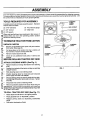
ASSEMBLY
.11 i
Your new tractor has been assembled at the factory with exception of those parts left unassemb[ed for shipping purposes.
To ensure safe and proper operation of your tractor, all parts and hardware you assemble must be tightened securely. Use
the correct tools as necessary to insure proper tightness.
TOOLS
REQUIRED
FOR ASSEMBLY
STEERING
A socket wrench set will make assembly easier. Standard
wrench sizes are listed.
(1) Tire pressure gauge
(1) 3/4" wrench
(1) Utility knife
another free manual from www.searstractormanuals.com
(2) 7/16" wrenches
_--_'_"
INSERT
__
HEX LOCKNUT
I
j_._._._
(1) 1/2" wrench
@
When right and left hand are mentioned in this manual, it
means when you are in the operating position (seated
behind the steering wheel).
TO REMOVE TRACTOR FROM CARTON
UNPACK
CARTON
•
Remove all accessible loose parts and parts cartons
from carton (See page 6).
•
Cut along lines on the carton, from top to bottom, all
four comers of carton and lay panels flat.
Remove mower deck from skid.
•
•
STEERING
WHEEL
ADAPTER
SHAFT
STEERING
STEERING
SLEEVE
Check for any additional loose parts or cartons and
remove.
/
/
/
/
/
/
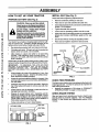
BEFORE ROLLING TRACTOR OFF SKID
ATrACH
STEERING
/
WHEEL (See Fig. 1)
•
Remove Iocknut and large flat washer from steering
shaft.
•
Position front wheels of the tractor so they are pointing
straight forward.
•
•
Slide steering sleeve over steering shaft.
Position steering wheel so cross bars are horizontal
(left to right) and slide onto adapter.
•
Secure steering wheel to steering shaft with hex locknut and large flat washer previously removed. Tighten
securely.
FIG. 1
•
Snap insert into center of steering wheel.
•
Remove protective plastic from tractor hood and grill.
IMPORTANT: CHECK FOR AND REMOVE ANY STAPLES
IN SKID THAT MAY PUNCTURETIRES WHERE TRACTOR
IS TO ROLL OFF SKID.
TO ROLL TRACTOR
OFF SKID (See Fig. 11)
•
Raise attachment lift lever to its highest position.
•
Place gearshift lever in "NEUTRAL" position.
•
Release parking brake by depressing clutch/brake
pedal.
Ro]l tractor backwards off skid.
•
WHEEL
FLAT
WASHER
7
ASSEMBLY
HOW TO SET UP YOUR TRACTOR
INSTALL
SEAT
(See Fig. 3)
Adjust seat before tightening adjustment bolt.
another free manual from www.searstractormanuals.com
PREPARE
BA'I-FERY
(See
Fig. 2)
CAUTION: Wear eye and face shield.
Wash hands or clothing immediately if
accidentally in contact with battery acid.
Do not smoke. Fumes from charged
battery acid are explosive.
Read the instructions included with the
battery vent caps. Always wear gloves,
clothing and goggles to protect your
hands, skin and eyes.
ii l= |
Your tractor has a battery charging system which is sufficient for normal use. However, periodic charging of the
battery with an automotive charger will extend its life.
•
See instructions packed with vent caps in parts bag.
°
Fill battery with acid. Fill each cell until it reaches the
bottom of the vent wells. Do not overfill.
•
Allow battery to stand and settle for at least thirty
minutes. After standing, check the level of acid. If
below the vent wells, add more acid until the correct
level is reached.
•
Remove cardboard packing on seat pan.
•
•
Place seat on pan and assemble shoulder bolt.
Assemble adjustmentbolt, Iockwasherandflatwasher
loosely. Do not tighten.
•
Tighten shoulder boltsecure[y.
•
•
Lower seat intooperating positionand sit on seat.
Slide seat untila comfortable positionisreached which
allows you to press clutch!brake pedal all the way
down.
•
Get off seat without moving its adjusted position.
•
Raise seat and tighten adjustment bolt securety.
SEAT
SEAT PAN
SHOULDER
BOLT
While battery is standing (after adding acid) and later, while
battery is being charged, continue with assembly of tractor.
IMPORTANT:
TO MAXIMIZE THE LIFE OF YOUR
BATTERY, IT IS NECESSARY THAT THE BATTERY BE
CHARGED BEFORE USE.
FAILURE TO CHARGE
BATTERY CAN RESULT IN A SHORTENED BATTERY
LIFE.
°
•
ADJUSTMENT
BOLT
Charge battery at a rate of 6 amperes for 1 hour. Use
a 12 volt battery charger. Observe alt safety precautions required for battery charging.
Check the acid level after the battery is charged. If the
acid has fallen below the correct level, add distilled or
iron free water.
•
Installthe vent caps to cover the vent wells. Wash the
top of the battery with water to remove any acid, then
wipe dry.
•
Check battery case for leakage to make sure that no
damage has occurred in handling.
•
Dispose of excess battery acid. Neutralize acid for
disposal by adding it to four inches of water in a five
gallon plastic container. Stir with a wooden or plastic
paddle while adding baking soda until the addition of
more soda causes no more foaming.
•
FLAT WASHER
FIG. 3
CHECK TIRE PRESSURE
The tires on yourtractorwere overinflated atthe factory for
shipping purposes, Correct tire pressure is importantfor
best cutting performance,
•
VENT
Reduce tire pressure to PSI shown in "PRODUCT
SPECIFICATIONS on page 3 of this manual,
CHECK BRAKE SYSTEM
After you learn how to operate your tractor, check to see
that the brake is properly adjusted. See 'q'O ADJUST
BRAKE" in the Service and Adjustments section of this
manual.
Follow instructions on how to install battery.
CUT AWAY VIEW
_LOCKWASHER
CAP
VENTWELL
BATI'ERY
CELL ACID
FIG. 2
8
i
ASSEMBLY
another free manual from www.searstractormanuals.com
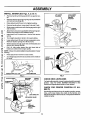
INSTALL MOWER
(See Figs. 4, 5, 6 & 7)
•
Remove banding holding parallel linkup against tractor.
•
Remove retainersecuring long hingepinto parallellink
and remove long hinge pin.
•
•
Raise attachment lift lever to its highest position.
Remove banding from mower deck links and V-belt.
•
Slidemowerundertractorwithdischargeguardtoright
side of tractor.
•
Attach front of mower to parallel linkwith long hinge pin.
Secure long hinge pin with retainer spring.
Install clutch rod in clutch lever. Secure with retainer
spring.
Turn height adjustment knob to its lowest setting.
•
•
•
Lower attachment lift lever to lower suspension arms.
Remove retainer springs from lift trunnions.
•
Slide trunnions through upper hole in lift brackets and
secure with retainer springs.
LIFT LEVER
PLUNGER
POSITION
__
75"
HIGHEST
POSITION
/
KNOB,
Pull L.H. idler pulley toward the right hand side of
tractor and roll belt over engine pulley.
NOTE: Mower drive belt installation decal located on mower
housing.
•
Raise attachment lift lever to raise mower,
LOWEST
FIG. 6
RAISE
Turn height adjustment knobclockwisetothe middle of
its travel.
0(3
,,,
,','
•
•
ATI'ACHM ENT
LIFT LEVER
HEIGHT
ADJUSTMENT
KNOB
oo
LOWER
MOWER PARALLEL LINK
LONG HINGE PIN
FIG. 4
CLUTCH
FIG. 7
RETAINER
SPRINGS
ENGINE
CHECK DECK LEVELNESS
For bestcutting results, mower housingshouldbe properly
leveled. See 'q'O LEVEL MOWER HOUSING" in the
Service and Adjustments section of this manual.
SUSPENSIO_
CHECK
BELTS
ROD
DISCHARGE GUARD
RETAINER
LIFT
BRACKET
(USE UPPER
HOLES)
FIG. 5
POSITION
OF ALL
See the figures that are shown for replacing motion,mower
drive, and mower blade drive belts in the Service and
Adjustments section of this manual. Verifythat the belts are
routed correctly.
LONG HINGE PIN
LIFT
TRUNNION
FOR PROPER
9
ASSEMBLY
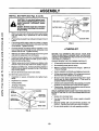
INSTALL BATTERY
CAUTION:
(See Figs. 8 and 9)
Do not short battery termi-
metal bracelets, wristwatch bands,
rings,
etc.
nals. Before
installing battery, remove
Positive terminal must be connected
first to prevent sparking from accidental grounding.
DOORS
another free manual from www.searstractormanuals.com
w
•
Make sure drain tube isfastened to drain hole in battery
tray and battery tray is positioned in hole of battery
•
support.
Place battery in plastic tray, battery terminals to front of
tractor.
•
First connect RED battery cable to positive (+) battery
terminal with hex bolt, flat washer, lockwasherand hex
nut as shown. Tighten securely.
Connect BLACK grounding cable to negative (-) battery terminal with remaining hex bolt, flat washer, lock
washer and hex nut. Tighten securely.
Slide the two battery bolts through the terminal guard
and start the wing nuts onto the threads.
Position terminal guard over the battery as shown,
lower bolts into key holes and slide square shafts of
bolts into slots of key holes.
•
•
•
•
Tighten wing nuts by hand making sure battery bolts
remain in slots of the key holes in the battery support.
•
Replace air intake duct. Air duct should be placed so
that the bottom edge is between the lip of the battery
tray and the battery.
Be sure terminal access doors are closed.
•
BATTERY TRAY
FIG. 9
J CHECKLIST
BEFORE YOU OPERATE AND ENJOY YOUR NEW
TRACTOR, WE WISH TO ASSURE THAT YOU RECEIVE
THE BEST PERFORMANCEAND SATISFACTION FROM
THIS QUALITY PRODUCT.
PLEASE REVIEW THE FOLLOWING CHECKLIST:
Use terminal access doors for:
•
Inspection for secure connections (to tighten hard-
,
ware).
Inspection for corrosion.
•
•
Testing battery.
Jumping (if required).
,/
All assembly instructions have been completed.
#"
No remaining loose parts in carton.
J
Battery is properly prepared and charged. (Minimum
1 hour at 6 amps).
,/
Seat is adjusted comfortably and tightened securely.
J
All tires are properly inflated. (For shipping purposes,
the tires were over-inflated at the factory).
J
Be sure mower deck is properly leveled side-to-side/
front-to-rear for best cutting results. (Tires must be
properly inflated for leveling).
Check mowerand drive belts. Be surethey are routed
properly around pulleys and inside all belt keepers.
/
/
1
I
I
HEX NUTL'_.:"':;
•/"
:"_
_
(POSITIVE)
WHILE LEARNING HOW TO USE YOUR TRACTOR, PAY
EXTRA ATTENTION TO THE FOLLOWING IMPORTANT
ITEMS:
/
/
/
(NEGATIVE)
/ S ,CKCABLE
....j
Check wiring. See that all connections are still secure
and wires are propedy clamped.
v"
Engine oil is at proper level.
J
Fuel tank is filled with fresh, clean, regular unleaded
gasoline.
Become familiar with all controls-their location and
function. Operate them before you start the engine.
J
J
RG. 8
10
Be sure brake system is in safe operating condition.
OPERATION
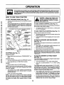
KNOW YOUR TRACTOR
READ THIS OWNER'S
MANUAL AND SAFETY RULES BEFORE OPERATING
YOUR TRACTOR.
Compare the illustrationswith yourtractorto familiarize yourselfwith the locationof various controlsand adjustments. Save
this manual for future reference.
ATrACHMENT
IGNITION SWITCH
CLUTCH LEVER
LIFT LEVER PLUNGER
another free manual from www.searstractormanuals.com
LIGHT SWITCH
CHOKE
ATTACHMENT
LIFT LEVER
PEDAL
BRAKE LEVER
THRO'n'LE
CONTROL
GEARSHIFT LEVER
HEIGHT ADJUSTMENT
KNOB
FIG. 10
Sears tractors conform to the safety standards of the American National Standards Institute.
LIFT LEVER PLUNGER - Used to release attachment lift
lever when changing its position.
GEARSHIFT LEVER - Selects the speed and direction of
the tractor.
LIGHT SWITCH - Turns the headlights on and off.
PARKING BRAKE LEVER- Locks clutch/brake pedal into
the brake position.
THROI"rLE CONTROL - Used to control engine speed.
CHOKE CONTROL - Used when starting a cold engine.
ATFACHMENT CLUTCH LEVER- Used to engage mower
b]ades or other attachments mounted to your tractor.
ATTACHMENT LIFT LEVER - Used to raise and lower
mower deck or other attachments mounted to yourtractor.
CLUTCH/BRAKE PEDAL - Used for declutching and
braking the tractor and startingthe engine.
HEIGHTADJUSTMENT KNOB- Used toadjustthe mower
height.
IGNITION SWITCH = Used to start and stop the engine.
11
OPERATION
The operation of any tractor can result in foreign objects thrown into the eyes, which can result
in severe eye damage. Always wear safety glasses or eye shields before starting your tractor
and while moving. We recommend wide vision safety mask for over the spectacles or standard
safety glasses.
HOW TO USE YOUR
another free manual from www.searstractormanuals.com
TO SET PARKING
•
TRACTOR
CAUTION: Always stop tractor completely, asdescribed above, before leaving the operator's position; to empty
grass catcher, etc.
BRAKE (See Fig. 11)
Depress clutch!brake pedal intofull =BRAKE" position
and hold.
Place parking brake lever in "ENGAGED" position and
release pressure from clutch/brake pedal. Pedalshould
remain in "BRAKE" position. Make sure parking brake
will hold tractor secure.
A'I-rACHMENT
CLUTCH' LEVER "ENGAGED"
IGNITION
THROTTLE
CONTROL
TO USE CHOKE CONTROL
•
POSITION
TO USE THROTTLE
CONTROL
(See Fig. 11)
Always operate engine at full throttle.
•
CHOKE
PARKING BRAKE
"ENGAGED"
POSITION
"BRAKE"
POSITION
To engage choke control, pull knob out. Slowly push
knob in to disengage.
KEY
"DISENGAGED"
;ITION
CONTROL_
(See Fig, 11)
Use choke control whenever you are starting a cold engine.
Do not use to start a warm engine.
•
Operating engine at less than full throttle reduces the
battery charging rate.
Full throttle offers the best bagging and mower performance.
"DISENGAGED"
TO MOVE FORWARD
(See Fig. 11)
AND BACKWARD
The direction and speed of movement is controlled by the
gearshift lever.
GEARSHIFT LEVER
CLUTCHFIBRAKE PEDAL
"DRIVE'POSITION
HEIGHT ADJUSTMENT
KNOB
Start tractor with clutch/brake pedal depressed and
gearshift lever in "NEUTRAL" position.
•
Move gearshift lever to desired position.
•
Slowly release clutch/brake pedal to start movement.
IMPORTANT: BRING TRACTOR TO A COMPLETE STOP
BEFORE SHIFTING OR CHANGING GEARS. FAILURE
TO DO SO WILL SHORTEN THE USEFUL LIFE OF YOUR
TRANSAXLE.
FIG. 11
STOPPING
•
(See Fig. 11)
MOWER BLADES •
TO ADJUST MOWER CU'I-FING HEIGHT
(See Fig. 11)
Move attachment clutchlever to"DISENGAGED" position.
GROUND DRIVE °
The cuttingheightis controlledbyturningthe height adjustment knob in desired direction.
Depress clutch/brake pedal intofuII"BRAKE" position.
°
Move gearshift lever to "NEUTRAL" position.
ENGINE •
Move throttle controlto "SLOW"position.
•
Turn knob clockwise (_)
•
Turn knob counterclockwise
height.
to raise cutting height.
(v-_) to lower cutting
The cutting height range is approximately 1-1/4" to 3-3/4".
The heights are measured from the ground to the blade tip
with the engine not running. These heights are approximate and may vary depending upon soil conditions, height
of grass and types of grass being mowed.
NOTE: Failure to move throttlecontrolto "SLOW" position
and allowing engine to idle before stopping may cause
engine to "backfire".
•
Turn ignition key to =OFF" position and remove key.
Always remove key when leaving tractor to prevent
unauthorized use.
°
Never use choke to stop engine.
NOTE: Under certain conditionswhen tractor is standing
idle with the engine running, hot engine exhaust gasses
may cause "browning" of grass. To eliminate this possibility, always stop engine when stopping tractor on grass
areas.
12
•
The average lawn should be cut to approximately
2-1/2 inches during the cool season and to over 3
inches during hot months. For healthier and better
looking lawns, mow often and after moderate growth.
•
For best cutting performance, grass over 6 inches in
height should be mowed twice. Make the first cut
relatively high; the second to desired height.
i ii
OPERATION
TO OPERATE
MOWER
TO TRANSPORT
(See Figs. 11 & 12)
another free manual from www.searstractormanuals.com
Your tractor is equipped with an operator presence sensing
switch. Any attempt by the operator to leave the seat with
the engine running and the mower clutch engaged willshut
off the engine.
•
•
Raise attachment lift controlto highest position.
When pushing ortowing your tractor, be sure gearshift
lever is in "NEUTRAU' position.
•
Do not push tractor at more than five (5) MPH.
•
•
Select desired height of cut.
Lower mower with attachment lift control.
•
Start mower blades by engaging attachment clutch
control.
NOTE: To protect hood from damage when transporting
your tractor on a truck or trailer, be sure hood is closed and
securedtotractor. Use an appropriate means of tying hood
to tractor (rope, cord, etc.).
•
TO STOP MOWER BLADES - disengage attachment
clutchcontrol.
BEFORE STARTING THE ENGINE
CHECK ENGINE OIL LEVEL (See Fig. 13)
CAUTION: Do not operate the mower
without either the entire grass catcher,
on mowers so equipped, or the discharge guard in place.
•
•
The engine in your unit has been shipped, from the
factory, already filled with summer weight oi!.
Check engine oil with unit on level ground.
•
Remove oilfi]l cap/dipstick and wipe clean, reinsert the
dipstick and screw cap tight, wait for a few seconds,
remove and read oil level. If necessary, add oil until
"FULL" mark on dipstick is reached. Do not overfill.
•
For cold weather operation you should change oil for
easier starting (See "OIL VISCOSITY CHART' in the
Customer Responsibilities section of this manual).
•
To change engine oil, see the Customer Responsibilities section in this manual.
R.H.
RUNNER
DISCHARGE
GUARD
ENGINE OIL FILL CAP/DIPSTICK
FIG. 12
TO OPERATE
ON HILLS
iii
i
i ii
hills with slopes greater than 15 ° and
CAUTION:
not drive
up or down
do not drive Do
across
any slope.
J
i
Choose the slowest speed before starting up or down
hills.
•
Avoid stopping or changing speed on hills.
•
If slowing is necessary, move throttle control lever to
slower position.
•
If stopping is absolutely necessary, push clutch!brake
pedal quickly to brake position and engage parking
brake.
FIG. 13
Move gearshift lever to 1st gear. Be sure you have
allowed room for tractor to roll slightly as you restart
movement.
To restart movement, slowly release parking brake and
clutch/brake pedal.
Make all turns slowly.
13
|
OPERATION
m
i
i
MOWING TIPS
•
•
Tire chains cannot be used when the mower housing
is attached to tractor.
•
Mower should be,properly leveled for best mowing
performance. See q-O LEVELMOWER HOUSING" in
the Service and Adjustments section of this manual.
•
Use the runner on the right hand side of mower as a
guide. The blade cuts approximately an inch outside
the runner (See Fig. 13).
The left hand side of mower should be used for trimming.
Drive so that clippings are discharged onto the area
that has been cut. Have the cut area to the right of the
tractor. This will result in a more even distribution of
clippings and more uniform cutting.
Fill fuel tank.
Use fresh, clean, regular unleaded
gasoline. (Useof leaded gasolinewill increasecarbon
and lead oxide deposits and reduce valve life).
IMPORTANT:
WHEN OPERATING IN TEMPERATURES
BELOW 32°F(0°C), USE FRESH, CLEAN WINTER GRADE
GASOLINE TO HELP INSURE GOOD COLD WEATHER
STARTING.
another free manual from www.searstractormanuals.com
i
ADD GASOLINE
WARNING: Experience indicates that alcohol blended
fuels (called gasohol or using ethanol or methanol) can
attract moisturewhich leads toseparation and formation of
acids during storage. Acidic gas can damage the fuel
system of an engine while in storage. To avoid engine
problems, the fuel system should be emptied before storage of 30 days or longer. Drain the gas tank, start the
engine and let it run until the fuel lines and carburetor are
empty. Use fresh fuel next season. See Storage Instructions for additional information. Never use engine or
carburetor cleaner products in the fuel tank or permanent
damage may occur.
•
•
CAUTION: Fill to bottom of gas tank
filler neck. Do not overfill. Wipe off any
spilled oil or fuel. Do not store, spill or
use gasoline near an open flame.
•
When mowing large areas, start by turning to the right
so that clippings will discharge away from shrubs,
fences, driveways, etc. After one or two rounds, mow
in the opposite direction making left hand turns until
finished (See Fig. 14).
•
If grass is extremely tall, it should be mowed twice to
reduce load and possible fire hazard from dried clippings. Make first cut relatively high; the second to the
desired height.
Do not mow grass when it is wet. Wet grass will plug
mower and leave undesirable clumps. Allow grass to
dry before mowing.
•
TO START ENGINE (See Fig. 11)
When starting engine for the first time or if engine has run
out of fuel, it willtake extra crankingtime to move fuel from
the tank to the engine.
•
Depress the clutch/brake pedal and set the parking
brake.
•
•
Place gearshift lever in "NEUTRAL" position.
Move attachment clutch to "DISENGAGED" position.
•
Pull choke control out to "CHOKE" position for cold
engine start. For warm engine start do not use choke
control.
•
Move throttle control to midway between "FAST" and
"SLOW" positions.
-
Insert key into ignitionand turn ignition key clockwise
to "START" position and release key as soon as engine
starts. Do not run starter continuously for more than
fifteen seconds per minute. If engine does not start
after several attempts, move throttle control to "FAST"
position, wait a few minutes and try again.
When engine starts, slowly push choke control in.
=
•
Move throttle control to"FAST" position.
•
Allow engine to warm up for a few minutes before
engaging clutch/brake pedal or attachment clutch
switch.
•
Always operate engine at full throttle when mowing to
assure better mowing performance and proper discharge of material. Regulate ground speed by selecting a low enough gear to give the mower cutting
performance as well as the quality of cut desired.
•
When operating attachments, select a ground speed
that will suit the terrain and give best performance of
the attachment being used.
f
FIG. 14
NOTE: If at a high altitude (above 3000 feet) or in cold
temperatures (below 32 ° F), the carburetor fuel mixture
may need to be adjusted for best engine performance. See
=TO ADJUST CARBURETOR" in the Service and Adjustments section of this manual.
14
i1|11|11
CUSTOMER
another free manual from www.searstractormanuals.com
III
.v,c
_(.0_
I
Check BrakeOperation
Ik##
V'
CheckTire Pressure
V'
V P
Checkfor LooseFasteners
Sharpen/ReplaceMower Blades
V'
If
1_4
C_ LubricationChart
f Check BatteryLevel/Recharge
0 Clean Batteryand Terminals
R
CheckTransaxleCooling
v'
v'
!_
V'
V'
.V'_..s
AdjustMotionDrive Belt(s)Tension
V'5
IIII
I
Check EngineOil Level
If
Change EngineOil
E
V'
Ik/
Clean AirFilter
N Clean AirScreen
G InspectMuffler/Spark
Arrester
I
....
V'
Adjust BladeBelt(s)Tension
I
i i
RESPONSIBILITIES
AS YOU COMPLETE
R EGU LAR SERVICE
iii ii
11_1,2,3
V'2
_.2
Ik_
._
V F
ReplaceOil Filter (Ifequipped)
1_1,2
Clean EngineCoolingFins
t##'2
N
.......
ReplaceSparkPlug
If
ReplaceAirFilter PaperCartridge
V'2
V p
ReplaceFuelFilter
V_,,,
3 - If equipped with oil filter, change oil every 50 hours.
4 - Replace blades more often when mowing in sandy soil.
5 - If equipped with adjustable system.
1 - Change more often when operating under a heavy load or in high ambient temperatures.
2 - Service more often when operating in dirty or dusty conditions.
GENERAL
LUBRICATION
RECOMMENDATIONS
CHART
ZERK@
The warranty on this tractor does not cover items that have
been subjected to operator abuse or negligence. To
receive fu]l value from thewarranty, operator mustmaintain
tractor as instructedin this manual.
Some adjustments will need to be made periodically to
properly maintain your tractor.
(If equipped)
(If equipped)
BEARING ZERK
BEARING
All adjustments in the Service and Adjustmentssection of
this manual should be checked at least once each season.
Once a year you should replace the spark plug, clean
or replace air filter, and check blades and belts for
wear. A new spark plug and clean air filter assure
proper air-fuel mixture and help your engine run better
and last longer.
BEFORE
®
O
CLUTCH
PIVOT(S)
EACH USE
•
•
Check engine oil level.
Check brake operation.
•
•
Check tire pressure.
Check for loose fasteners.
ZERK
t
@SAE
PIVOTS
@
30 OR I0W30 MOTOR OIL API - SG
@GENERAL
(_REFER
J
PURPOSE GREASE
TO CUSTOMER RESPONSIBILITIES
"'ENGINE" SECTION
IMPORTANT:
DO NOT OIL OR GREASE THE PIVOT POINTS
WHICH HAVE SPECIAL NYLON BEARINGS.
VISCOUS LUBRICANTS WILL ATTRACT DUST AND DIRT THAT WILL SHORTEN
THE LIFE OF THE SELF-LUBRICATING
BEARINGS.
IF YOU
FEEL THEY MUST BE LUBRICATED,
USE ONLY A DRY, POW15 DERED GRAPHITE TYPE LUBRICANT SPARINGLY.
CUSTOMER
RESPONSIBILITIES
TRACTOR
TO SHARPEN
Always observe safety rules when performing any mainteRanGe.
Care should be taken to keep the biade balanced. An
unbalanced blade will cause excessive vibration and eventual damage to mower and engine.
BRAKE OPERATION
•
another free manual from www.searstractormanuals.com
If tractor requires more than six (6) feet stopping distance
at high speed in highest gear, then brake must be adjusted.
(See 'qO ADJUST BRAKE" in the Service and Adjustments section of this manual).
The blade can be sharpened with a fife or on a grinding
wheel. Do not attempt to sharpen while on the mower.
To check blade balance, drive a nail into a beam or wall.
Leave about one inch of the straight nail exposed.
Place center hole of blade over the head of the nail. If
blade is balanced, it should remain in a horizontal
position. If either end of the blade moves downward,
sharpen the heavy end until the blade is balanced.
•
TIRES
•
Maintain proper air pressure in all tires (See"PRODUCT SPECIFICATIONS" on page 3 of this manual).
•
Keep tires free of gasoline, oil, or insect control chemicals which can harm rubber.
•
Avoid stumps, stones, deep ruts, sharp objects and
other hazards that may cause tire damage.
BLADE (See Fig. 16)
CENTER
HOLE
BLADE CARE
For best resutts mower blades must be kept sharp. Replace bent or damaged blades.
BLADE REMOVAL
FIG. 16
(See Fig. 15)
•
Raise mower to highest position to allow access to
blades.
•
Remove hex bolt, lock washer and fiatwasher securing
blade.
•
Install new or resharpened blade with trailing edge up
towards deck as shown.
•
Reassemble hex bolt, lock washer and flat washer in
exact order as shown.
BATTERY (See Fig. 17)
Your tractor has a battery charging system which is sufficient for normal use. However, periodic charging of the
battery with an automotive charger will extend it's life.
•
Tighten bolt securely (30-35 Ft. Lbs. torque).
IMPORTANT: BLADE BOLT IS GRADE 5 HEAT TREATED.
NOTE: We do not recommend sharpening blade- but if you
do, be sure the blade is balanced.
•
Acid solution level in each battery cell should be even
with bottoms of vent wells. Add only distilled or iron free
water if necessary. Do not overfill.
•
Keep battery and terminals clean.
•
•
Keep battery bolts tight.
Keepvent capstight and small vent holesin caps open.
•
Recharge at 6 amperes for 1 hour.
CUT AWAY VIEW
VENT CAP
MANDREL
ASSEMBLY
B LA D E _._
1
,
,
_
,
TRAILING
EDGE UP
lJ
VENT
BA'I-rERY
CELL ACID
LEVEL
HEX BOLT
(GRADE 5)*
LOCK WASHER
(_
,
__
FIG. 17
IDENTIFIED
BY THREE
LINES BOLT
ON THE
*A
GRADE 5 HEAT
TREATED
CAN BOLT
BE
HEAD AS SHOWN AT LEFT.
FIG. 15
16
CUSTOMER
RESPONSIBILITIES
i
another free manual from www.searstractormanuals.com
TO CLEAN BATTERY AND TERMINALS Corrosion and dirt on the battery and terminals can cause
the battery to "leak" power.
TO CHANGE ENGINE OIL (See Fig. 18) Determine temperature range expected before oil change.
All oil must meet API service classification SG.
•
Remove terminal guard.
•
Be sure tractor is on level surface.
•
Disconnect BLACK battery cable first then RED battery cable and remove battery from tractor.
•
•
Oil will drain more freely when warm.
Catch oil in a suitable container.
•
Wash battery with solution of four tablespoons of
baking soda to one gallon of water. Be careful not to get
the soda solution into the cells.
•
Remove oil filler cap. Be careful notto allow dirtto enter
the engine when changing oil.
•
Rinse the battery with plain water and dry.
•
Clean terminals and battery cable ends with wire brush
until bright.
Coat terminals with grease or petroleum jelly.
•
•
Remove drain plug.
After oil has drained completely, replace oil drain plug
and tighten securely.
Refill engine with oil through oi] fill dipsticktube. Pour
slowly. Do not overfill. For approximate capacity see
"PRODUCT SPECIFICATIONS" on page 3 of this
manual.
•
•
•
Reinstall battery (See "INSTALL BA-I-I-ERY" in the
Assembly section of this manual).
•
V- BELTS
Check V-Belts for deterioration and wear after 100 hours
and replace if necessary. The mower blade drive belt can
be adjusted to provide you with longer belt life (See "TO
ADJUST MOWER BLADE DRIVE BELT" in the Service
and Adjustments section of this manual). The motion drive
belt is not adjustable. Replace belts if they begin to slip from
wear.
TRANSAXLE
Use _auge on oil fill dipstick for checking level. Besure
dipstzck ts tightened securely for accurate reading.
Keep oil at "FULL" line on dipstick.
OIL DRAIN PLUG-_,
ENGINE OIL FILL
COOLING
Keep transaxle free from build-up of dirt and chaff which
can restrictcooling.
F
AIR SCREEN
'/_
CAP/D]PSTlC K"-__...i,__
FIG. 18
ENGINE
CLEAN AIR SCREEN (See Fig. 18)
LUBRICATION
The air screen must be kept free of dirtand chaff to prevent
engine damage from overheating. Clean with a wire brush
or compressed air to remove dirt and stubborn dried gum
fibers.
Only use high quality detergent oil rated with API service
classification SG. Select the oirs SAE viscosity grade
according to your expected operating temperature.
CLEAN ENGINE COOLING
SAEVISCOSITYGRADES
Remove any dust, dirt or oil from engine cooling fins to
prevent engine damage from overheating. Engine blower
housing must be removed. Remove side panels and hood
(See'q'O REMOVE HOOD AND GRILL ASSEMBLY" inthe
Service and Adjustments section of this manual.)
<
°F
-20 °
"I'EMPERATORE
0 °'
"'
30 °
32 ° 40 °
RANGE ANTICIPATED
FINS
(See Fig. 19)
60 °
80"
100 °
BEFORE NEXT OIL CHANGE
NOTE: Although multi-viscosity oils (5W30, 10W30, etc.)
improve starting in cold weather, these multi-viscosity oils
will result in increased oil consumption when used above
32°F. Check your engine oil level more frequently to avoid
possible engine damage from running low on oil.
TOP AIR GUIDE
COVER
__,
Change the oil after the first two hours of operation and
every 25 hours of operation thereafter or at least once a
year if the tractor is not used for 25 hours in one year.
NG,NE
COOL,
NG
RNS ,
AIR GUIDE COVER____
Check the crankcase oil level before starting the engine
and after each eight (8) hours of operation. Tighten oil fill
cap/dipstick securely each time you check the oil level.
(BOTH SIDES) ......--r
,,
FIG. 19
17
CUSTOMER
RESPONSIBILITIES
AIR FILTER (See Fig. 20)
MUFFLER
Your engine will not run properly using a dirty air filter.
Clean the foam pre-cleaner element after every 25 hours of
operation or every season. Service paper cartridge every
100 hours of operation or every season, whichever occurs
first.
Inspect and replace corroded mufflerand spark arrester (if
equipped) as itcould create a fire hazard and/or damage.
SPARK PLUGS
Replace spark plugs at the beginning of each mowing
season or after every 100 hours of operation, whichever
comes first. Spark plug type and gap setting are shown in
"PRODUCT SPECIFICATIONS"on page 3 of this manual.
Service air cleaner more often under dusty conditions.
another free manual from www.searstractormanuals.com
•
Remove knob(s) and cover,
O SERVICE PRE-CLEANER -
T
Slide foam pre-cleaner off cartridge.
IN-LINE FUEL FILTER
•
•
•
•
Wash it in liquid detergent and water.
Squeeze it dry in a clean cloth,
Saturate it in engine oil. Wrap it in clean, absorbent
cloth and squeeze to remove excess oil.
Reinstall pre-cleaner over cartridge.
Thefuelfiltershouldbe replaced once each season. Iffuel
filter becomes clogged, obstructingfuel flow to carburetor,
replacement is required.
With engine cool, remove filter and plug fuel line
•
sections.
•
Reinstall cover and secure with knob(s).
•
Place new fuel filter in position in fuel line with arrow
pointingtowards carburetor.
•
Be sure there are no fuel line leaks and clamps are
properly positioned.
Immediately wipe up any spilled gasoline.
TO SERVICE CARTRIDGE Remove wing nuts and cartridge plate,
•
Remove cartridge and clean by tapping gentlyon flat
surface.
°
•
(See Fig. 21)
Ifve ry di rty,re p lace or wash detergent.
in a nonsudsing .
and warm water solution. Rinse thoroughly w_thwater
from inside out until water runs clear. Let cartridge dry
thoroughly before using.
•
Reinstall cartridge plate, wing nuts, precleaner, cover
and secure with knob(s).
IMPORTANT:
PETROLEUM SOLVENTS, SUCH AS
KEROSENE, ARE NOT TO BE USED TO CLEAN THE
CARTRIDGE. THEY MAY CAUSE DETERIORATION OF
THE CARTRIDGE. DO NOT OIL CARTRIDGE. DO NOT
USE PRESSURIZED
AIR TO CLEAN OR DRY
CARTRIDGE.
KNOB NUT
WING
[?
COVER
_
_
J
CARTRIDGE
Clean engine, battery, seat, finish, etc. of all foreign
PLATE
•
matter.
Keep
finished surfaces and wheels free ofall gasoline,
oil, etc.
•
Protect painted surfaces with automotive type wax.
We do not recommend using a garden hose to clean your
tractor unless the electrical system, muffler, air filter and
carburetor are covered to keep water out. Water in engine
can result in a shortened engine life.
PRE-CLEANER
CARTRIDGE
AIR SCREEN
FIG. 20
18
SERVICE AND ADJUSTMENTS
CAUTION: BEFORE PERFORMING ANY SERVICE OR ADJUSTMENTS:
Depress clutch/brake pedal fully and set parking brake.
Place gearshift lever in "NEUTRAL" position.
Place attachment clutch in "DISENGAGED" position.
Turn ignition key "OFF" and remove key.
Make sure the blades and all moving parts have completely stopped.
Disconnect spark plug wire from spark plug and place wire where it cannot come in contact with
plug.
another free manual from www.searstractormanuals.com
TO REMOVE
MOWER
TO LEVEL MOWER HOUSING
(See Fig. 22)
Adjust the mower while tractor is parked on level ground or
driveway. Make sure tires are properly inflated (See
"PRODUCT SPECIFICATIONS" on page 3). If tires are
over or underinflated, you will not properly adjust your
mower.
Mowerwill be easier to remove from the right side of tractor.
•
•
Remove mower drive belt from engine pulley only (See
"TO REPLACE MOWER DRIVE BELl" through step
removing belt from mower drive pulley.)
Remove retainer spring from clutch rod, pull clutch rod
out of clutch lever.
SIDE-TO-SIDE ADJUSTMENT (See Figs. 23 and 24)
•
Pull retainer springs out of rear suspension trunnions.
•
•
Remove rear suspension trunnions from lift brackets.
•
•
Pull retainer springs from front hinge pins.
Measure height from bottom deck curl to ground level
at front corners of mower. Distance "A" should be the
same.
•
Remove hinge pins attaching parallel linkto mowerand
front axle.
•
If distance "A" needs to be changed, snap out access
hole cover on left side of tractor above footrest.
Raise liftlever to raise suspension arms. Slide mower
out from under tractor.
•
To raise left side of mower, loosen nut"B" and tighten
nut "C".
IMPORTANT:
IF AN ATTACHMENT
OTHER THAN THE
MOWER DECK IS TO BE MOUNTED ON THE TRACTOR,
REMOVE THE LH. AND R.H. SUSPENSION ARMS AND
THE FRONT SUSPENSION
BRACKET.
•
To lower left side of mower, loosen nut"C" and tighten
nut "B".
•
When distance "A" is equal, securely tighten nuts "B"
and =C".
•
Replace access hole cover.
CLUTCH
LEVER
RETAINER
;PRINGS
Raise attachment lift lever to its highest position.
ENGINE
, PULLEY
ARMS
BOTTOM
=_
'7
BOTTOM
LINK
CURL
OF C_
FRONT
HINGE
PIN
REAR
SUSPENSION
TRUNNION
/
it,
ROD
RETAINER
FIG. 23
BRACKET
_
LIF'T
FIG. 22
TO INSTALL
MOWER
See "INSTALL MOWER" in the Assembly section of this
manual.
FIG. 24
19
SERVICE AND ADJUSTMENTS
TO ADJUST MOWER DRIVE BELT
(See Fig. 27)
FRONT-TO-BACK ADJUSTMENT (See Figs. 25 and 26)
To obtain the best cutting results, the mower housing
should be adjusted so the back is approximately 7/8" to
1-1/8" higher than the front when the mower is in highest
adjustment position.
Your tractor has been manufactured with the ability to readjustmower drive belt to provideyou with longer belt life.
If the attachment clutch lever travels forward in the slot
before springtension resistance is evident, adjustment is
necessary.
IMPORTANT: CHECK FOR PROPER SPRING TENSION
WITH ENGINE OFF AND LIFT LEVER IN HIGHEST
POSITION.
Measure distance "D" from ground line to bottom of deck
curl at centerline outside of mandrels.
another free manual from www.searstractormanuals.com
•
•
To raise rear of mower, loosen nut "E" on both rear
suspension arms. Screw both nuts "F' on both rear
suspension arms an equal number of turns.
When distance "D" is 7/8" to 1-1/8" higher at rear than
front, retighten nuts "E".
•
Recheck side-to-side adjustment.
IMPORTANT: WHEN ADJUSTING REAR SUSPENSION
ARMS, ALWAYS ADJUST BOTH EQUALLY SO MOWER
WILL STAY LEVEL SIDE-TO-SIDE.
•
Remove mower deck from tractor (See"TO REMOVE
MOWER" in this section of this manual).
•
Remove cotter pin from L.H. side of rock shaft assembly.
Loosen the four Iocknuts on the R.H. and L.H. pivot
brackets only until rock shaft assembly can be removed.
•
°
BACK
Remove extension spring from lower hole (original
_osition) in rock shaft assembly and place in upper
ole.
FRONT
"_"
+ 718" to 1-'L/8"
rI//iltF/2_,,_.Ffl///////////////i////!///
"D'_
FIG. 25
REAR
Remove rock shaft assembly from pivot brackets.
•
Replace rock shaft assembly making sure carriage
bolts are seated in square holes of mower housing.
•
Replace cotter pin on LH. side of rock shaft assembly.
NOTE: When installing a new belt, extension spring must
be returned to lower hole (original position) on rock shaft
assembly.
?
LOWER HOLE {ORIGINAL POSITION)
ARMSUSPENSION
_
NUT "E"
UPPER HOLE
/
EXTENSION
/.2>.
ROCK SHAFT
SPRING
BRAKE ROD
R.H.
PIVOT
.OT"F'
BRACKET
BRACKET-----'-r_
LOCKNUTS "Jr"--
"_
FIG. 27
FIG. 26
20
'OCKNOT
SERVICE AND ADJUSTMENTS
TO REPLACE
MOWER
(See Figs. 28 and 29)
DRIVE
BELT
TO REPLACE
•
Park the tractor on level surface. Engage parking brake.
BELT REMOVAL -
another free manual from www.searstractormanuals.com
MOWER
BLADE
DRIVE
BELT
(See Figs. 30, 31 and 32)
•
Remove mower (See'70 REMOVE MOWER" in this
section of this manual).
Remove mowerdrive belt (See"TO REPLACE MOWER
DRIVE BELl-" in this section of this manual).
Pull mower blade drive belt towards rear of mower at
tensioning pulley. Place a block between tensioning
pulley and pivot bracket. Roll belt off tensioning pulley.
•
Place attachment clutch in "DISENGAGED" position.
•
•
Turn height adjustment knob to lowest setting.
Move attachment liftlever forward to lower mowerto its
lowest position.
•
•
Roll belt off engine pulley.
•
Roll belt off all other pulleys.
•
Pull belt off mower pulley and both idler pulleys.
•
Slide belt from under spring.
•
•
Use pliers to remove brake spring.
Remove cotter pin from brake rod; then remove brake
rod from rock shaft assembly.
Pull belt out from under brake rod and off mower.
NOTE: Ifnecessary loosen guardsand beltguidesfor ease
of belt removal and installation.
•
BELT INSTALLATION -
•
•
•
Slide belt under spring.
Place belt around mower pulley and both idler pulleys.
•
Roll belt over engine pulley.
•
Makesure belt is in all pulleygrooves and insideall belt
guides.
ATTACHMENT
CLUTC.
"ENGAGED'°
To install belt, reverse above procedure.
belt is engaged in all pulleys.
Make sure
MOWER
TENSIONING
BLADE
PULLEY
DRIVE
BELT
ATTACHMENT LIFT
LEVER "HIGHEST"
/
,_.POSITION
POSITION __,
"DISENGAGED"
POSITION
HEIGHT _
"fL._J
.'.'
]
POSITION
_
°ol
BLOCK
FIG. 30
BRAKE
SPRING
FIG. 28
ENGINE PULLEY
BELT GUIDES
R.H. IDLER
PULLEY
LH. IDLER
PULLEY
FIG. 31
ROCK SHAFT
SPRING
ASSEMBLY
BRAKE ROD
COTTER PIN "----r
_'_/_
MOWER
PULLEY
PIVOT BRACKL_'_---_
MOWER DRIVE BELT
FIG. 29
21
FIG. 32
i
SERVICE AND ADJUSTMENTS
TO ADJUST
TO REPLACE
BRAKE (See Fig. 33)
Your tractor is equipped with an adjustable brake system
which is mounted on the right side of the transaxle.
another free manual from www.searstractormanuals.com
If tractor requires more than six (6) feet stopping distance
at high speed in highest gear, then brake must be adjusted.
•
•
Depress clutch!brake pedal and engage parking brake.
Measure distance between brake operating arm and
nut "A° on brake rod.
•
If distance is other than 1-12", disengage parking
brake, loosen jam nut and turn nut 'W' until distance
becomes 1-1/2". Retighten jam nut against nut "A".
•
Engage parking brake and recheck distance.
•
Road test unit for proper stopping distance as stated
above. Readjust if necessary. If stopping distance is
still greater than six (6) feet in highest gear, further
maintenance is necessary. Contact your nearest authorized service center.
MOTION
DRIVE
BELT
(See Fig. 34)
Park the tractor on level surface. Engage parkingbrake.
For assistance, there is a belt installationguide decal on
bottom side of left footrest.
•
Remove mower (See "TO REMOVE MOWER" in this
section of this manual.)
•
Remove upper belt keeper.
•
•
Remove belt from stationary idler and clutching idler.
Pull belt slack toward rear of tractor. Remove belt
upwards from transaxle pulley by deflecting belt keepers.
Pull belt toward front of tractor and remove downwards
from around engine pulley.
•
•
Install new belt by reversing above procedure.
IMPORTANT" MAKE SURE UPPER BELT KEEPER IS
POSITIONED PROPERLY BETWEEN LOCATOR TABS.
ENGINE "-----.t.I..._
WITH PARKING BRAKE "ENGAGED"
•.-. LOCATOR
TABS
IDLER
NUT "A"
_
STATIONARY
"_
IDLER
I!
_,
II
JAM NUT
TRANSAXLE,_
II
OPERATING ARM
FIG. 34
FIG. 33
22
"- UPPER BELT
KEEPER
i
,....,, .,,
i
.,..,,.,, i.
SERVICE AND ADJUSTMENTS
TRANSAXLE
SHIFTER LINKAGE
JUSTMENT (See Figs. 35 and 36)
AND AD-
TO ADJUST STEERING
If steering wheel crossbars are not horizontal (left to right)
when wheels are positioned straight forward, remove steering wheel and reassemble per instructions in the Assembly
section of this manual.
another free manual from www.searstractormanuals.com
The transaxle shouldbe in neutral when the gearshift lever
is in the neutral (lock gate) position. The adjustment is
preset at the factory; however, if adjustment is needed,
proceed as follows:
•
Make sure transaxle is in neutral.
•
Loosen two Iocknuts on tie rod.
•
Turn center rod until gearshift lever falls into neutral
lock gate on fender console.
•
Tighten Iocknuts securely.
WHEEL ALIGNMENT
FRONT WHEEL TOE-IN/CAMBER
The front wheel toe-in and camber are not adjustable on
your tractor. If damage has occurred to affect the front
wheel toe-in or camber, contact your nearest authorized
service center.
TO REMOVE WHEEL FOR REPAIRS
(See Fig. 37)
_GEARSHIFTLEVER
NEUTRAL
LOCK GATE,
FIG. 35
•
Block up axle securely.
•
Removeaxlecover, retaining ring andwashersto allow
wheel removal (rear wheel contains a square key - Do
not lose).
•
Repair tire and reassemble.
•
On rear whee]s only: align grooves in rear wheel hub
and axle. Insert square key.
•
Replace washers and snap retaining ring securely in
axle groove.
Replace axle cover.
•
WASHERS
_
_KNUTS
RETAINING
RING
AXLE
COVER
SQUARE KEY (REAR WHEELS ONLY)
FIG. 36
FIG. 37
23
i
i|
i iiii
ill l
i i i
SERVICE AND ADJUSTMENTS
TO REPLACE
TO START ENGINE WITH A WEAK BATTERY
(See Figs. 41 and 42)
ii
i
CAUTION:
another free manual from www.searstractormanuals.com
i
I
If your battery istoo weak to start the engine, it should be
recharged. If =jumper cables" are used for emergency
starting,follow this procedure:
IMPORTANT: YOUR UNIT IS EQUIPPED WITH A 12
VOLT NEGATIVE GROUNDED SYSTEM. THE OTHER
VEHICLE MUST ALSO BE A 12 VOLT NEGATIVE
GROUNDED SYSTEM. DO NOT USE YOUR TRACTOR
BATTERY TO START OTHER VEHICLES.
BULB
Raise hood.
•
Pull bulb holder out of the hole in the backside of the
grill.
•
Replace bulb in holderand push bulb holder securely
back into the hole in the backside of the grill.
Close hood.
Lead-acid batteries generate I
smoking materials away from batteries.
explosive
gases.
Keep sparks,
flame
and
Always wear
eye protection
when
around
batteries.
HEADLIGHT
•
•
INTERLOCKS
AND RELAYS
Loose or damaged wiring may cause your tractor to run
poorly, stop running, or prevent it from starting.
•
Check wiring. See electrical wiring diagram in Repair
Parts section of this manual.
TO REMOVE HOOD AND GRILL (See Fig. 43)
"POSITIVE"
"NEGATNE"
(+)
•
Raise hood.
•
Unsnap headlight wire connector.
•
Stand in front of tractor. Grasp hood at sides, tilt
forward and lift off of tractor.
•
To reinstall, slide hood pivot brackets into slots in
frame.
•
Reconnect headlight wire connector and close hood.
(-)
FIG. 41
TO A'I-FACH JUMPER CABLES •
Connect each end of the RED cable to the POSITIVE
(+) terminal of each battery, taking care not to short
against chassis.
•
Connect one end of the BLACK cable to the NEGATIVE (-) terminal of fully charged battery.
•
Connect the other end of the BLACK cable to good
CHASSIS GROUND, away from fuel tankand battery.
HEADLIGHT
WIRE
CONNECTOR
HOOD
FIG. 43
FIG. 42
TO REMOVE CABLES, REVERSE ORDER •
BLACK cable first from chassis and fully charged
battery.
•
RED cable last from both batteries.
24
SERVICE AND ADJUSTMENTS
ENGINE
TO
ADJUST
THROTTLE
CONTROL
CABLE
TO ADJUST CHOKE CONTROL
(See Fig. 41)
The throttle control has been preset at the factory and
adjustment should not be necessary. Checkadjustmentas
described below before loosening cable. If adjustment is
necessary, proceed as follows:
another free manual from www.searstractormanuals.com
(See Fig. 42)
The choke control has been preset at the factory and
adjustmentshouldnotbe necessary. Checkadjustrnentas
described below before loosening cable. If adjustment is
necessary, proceed as follows:
•
•
With engine not running, move throttle controllever to
"FAST" position.
•
•
Check that speed control lever isagainst stopscrew. If
it isnot, loosen clamp screw and pullthrottlecable until
lever isagainst screw. Tighten clamp screw securely.
•
CLAMP
•
With engine not running, movechoke control (located
on dash panel) to full CHOKE position.
Remove air cleaner cover, filter and spEtback plate to
expose carburetor choke (See "AIR FILTER" in the
Customer Responsibilities section of this manual).
Choke should be closed. If it is not, loosen casing
clamp screw and move choke until choke iscompletely
closed. Tighten casing clamp screw securely.
Reassemble air cleaner.
CHOKE
QUARTER
CIRCLE
CASING
CLAMP
CHOKE CONTROL
SWIVEL
FIG. 42
FIG. 41
25
SERVICE AND ADJUSTMENTS
TO ADJUST CARBURETOR
(See Figs, 43 and 44)
High speed stop isfactory adjusted. Do not adjust-damage
may result.
IMPORTANT;
NEVER TAMPER WITH THE ENGINE
GOVERNOR,
WHICH IS FACTORY SET FOR PROPER
ENGINE SPEED. OVERSPEEDING THE ENGINE ABOVE
THE FACTORY
HIGH SPEED
SETTING
CAN BE
DANGEROUS.
IFYOUTHINKTHE
ENGINE-GOVERNED
HIGH SPEED NEEDS ADJUSTING,
CONTACT
YOUR
NEAREST
SEARS SERVICE
CENTER,
WHICH HAS
PROPER EOUIPMENTAND
EXPERIENCE TO MAKE ANY
NECESSARY ADJUSTMENTS.
another free manual from www.searstractormanuals.com
The carburetor has been present at the factory and adjustment should not be necessary. However, minor adjustment may be requiredto compensate for differences in fuel,
temperature, altitude or load. If the carburetor does not
need adjustment, proceed as follows:
In general, turning the mixture screw in (clockwise) decreases the supply of fuel to the engine giving a leaner fuel/
air mixture. Turning the mixture screw out (counterclockwise) increases the supply of fuel to the engine giving a
richer fuel/air mixture.
IMPORTANT:
DAMAGE
SEATS IN CARBURETOR
TURNED IN TOO TIGHT.
IDLE SPEED
;REW
TO THE NEEDLES AND THE
MAY RESULT IF SCREW IS
PRELIMINARY SETTING •
Be sure you have a clean air filter, and the throttle
control cable and choke are adjusted properly (see
above).
IDLE MIXTURE
SCREW
•
With engine off turn idle mixture screw in (clockwise)
closing it finger tight and then turn out (counterclockwise) 1-1/4 to 1-1/2 turns.
FINAL SETTING •
Start engine and allow to warm for five minutes. Make
final adjustments with engine runningand shift!motion
controllever in "NEUTRAU' position.
•
With throttle control lever in "SLOW" position, hold
throttle lever against idle speed screw and adjust idle
speed screw to obtain 1200 to 1400 RPM.
•
•
THRO'R'LE LEVER
FIG. 43
IDLE SPEED
SCREW
While still holding throttle lever against idle speed
screw, turn idle mixture screw in (clockwise) until
engine begins to die and then turn out (counterclockwise) until engine runs rough. Turn screw to a point
midway between those two positions.
Continue to hotdthrottle lever against idlespeed screw
and adjustidlespeed screw to obtain900to 1200 RPM.
Release throttle lever.
ACCELERATION TEST•
Move throttle control lever from "SLOW" to "FAST"
position. If engine hesitates or dies, turn idle mixture
screw out (counterclockwise) 1/8 turn. Repeat test
and continue to adjust, if necessary, until engine accelerates smoothly.
THRO'I-rLE LEVER
IDLE MIXTURE SCREW
FIG. 44
26
iiii iii
i
STORAGE
Immediately prepare your tractor for storage at the end of
the season or if the tractor will not be used for 30 days or
more.
ENGINE
FUEL SYSTEM
IMPORTANT:
IT IS IMPORTANT
TO PREVENT GUM
DEPOSITS
FROM FORMING
IN ESSENTIAL
FUEL
SYSTEM PARTS SUCH AS CARBURETOR, FUEL FILTER,
FUEL HOSE, OR TANK DURING STORAGE.
ALSO,
EXPERIENCE
INDICATES THAT ALCOHOL BLENDED
FUELS (CALLED GASOHOL OR USING ETHANOL OR
METHANOL) CAN ATTRACT MOISTURE WHICH LEADS
TO SEPARATION AND FORMATION OF ACIDS DURING
STORAGE.
ACIDIC GAS CAN DAMAGE THE FUEL
SYSTEM OF AN ENGINE WHILE IN STORAGE.
another free manual from www.searstractormanuals.com
CAUTION: Never store the tractor with
gasoline in the tank inside a building
where fumes may reach an open flame or spark. Allow the engine to cool
before storing In any enclosure.
TRACTOR
Drain the fuel tank.
Remove mower from tractor for winter storage. When
mower is to be stored for a period of time, clean it thoroughly, remove all dirt, grease, leaves, etc. Store in a
clean, dry area.
°
•
Start the engine and let it run until the fuel lines and
carburetor are empty.
Never use engine or carburetor cleaner products in the
fuel tank or permanent damage may occur.
Use fresh fuel next season.
Clean entire tractor (See"CLEANING" in the Customer
Responsibilities section of this manual).
Inspect and replace belts, if necessary (See belt replacement instructions inthe Service and Adjustments
section of this manual).
NOTE: Fuel stabilizer is an acceptable alternative in
minimizing the formation of fuel gum deposits during storage. Add stabilizer to gasoline in fuel tank or storage
container. Always follow the mix ratio found on stabilizer
container. Run engine at least 10 minutes after adding
stabilizer to allow the stabilizer to reach the carburetor. Do
not drain the gas tank and carburetor if using fuel stabilizer.
Lubricate as shown in the Customer Responsibilities
section of this manual.
Re sure that all nuts, bolts and screws are securely
fastened. Inspect moving parts for damage, breakage
and wear. Replace if necessary.
ENGINE OIL
Touch up all rusted or chipped paint surfaces; sand
lightly before painting.
BA'n'ERY
Drain oil (with engine warm) and replace with clean engine
oil. (See "ENGINE" in the Customer Responsibilities
section of this manual).
•
•
Fully charge the battery for storage.
After a period of time in storage, battery may require
recharging.
CYLINDERS
•
To help prevent corrosion and power leakage during
long periods of storage, battery cables should be
disconnected and battery cleaned thoroughly (see'q-O
CLEAN BATTERY AND TERMINALS" in the Customer Responsibilities section of this manual).
•
After cleaning, leave cables disconnected and place
cables where they cannot come in contact with battery
terminals.
•
Be sure battery drain tube is securely attached.
•
If battery is removed from tractor for storage, do not
store battery directly on concrete or damp surfaces.
•
•
Remove spark plug(s).
Pour one ounce of oil through spark plug hole(s) into
cylinder(s).
•
Turnignitionkeyto"START"positionforafewseconds
to distribute oil.
•
Replace with new spark plug(s).
OTHER
•
•
•
•
Do not store gasoline from one season to another.
Replace your gasoline can if your can starts to rust.
Rust and/or dirt in your gasoline will cause problems.
If possible, store your tractor indoors and cover it to
give protectionfrom dust and dirt.
Cover your tractorwith a suitable protective cover that
does not retain moisture. Do not use plastic. Plastic
cannot breathe which allows condensationtoform and
will cause your tractor to rust.
IMPORTANT: NEVER COVER TRACTOR WHILE ENGINE
AND EXHAUST AREAS ARE STILL WARM.
27
another free manual from www.searstractormanuals.com
TROUBLESHOOTING
POINTS
PROBLEM
CAUSE
CORRECTION
Will not start
t.
2.
3.
4.
5.
6.
7.
Out of fuel.
Engine not "CHOKED" pmpedy.
Engine flooded.
Bad spark plug.
Dirty air filter.
Dirty fuel filter.
Water in fuel.
1.
Fill fuel tank.
2.
3.
4.
5.
6.
7.
8.
9.
10.
Loose or damaged widng.
Carburetor out of adjustment.
Engine valves out of adjustment.
8.
9.
!0.
See =TO START ENGINE" in Operation section.
Wait several minutes before attempting to start.
Replace spark plug.
Clean/replace air filter.
Replace fuel filter.
Drain fuel tank and carburetor, refill tank w_thfresh
gasoline and replace fuel filter.
Check all wiring.
Contact an authorized service center/department.
Contact an authorized service center/departmanL
Hard to start
1.
2,
3.
4.
5.
6.
7.
8.
Dirty air filter.
Bad spark plug.
Weak or dead battery.
Dirty fuel filter.
Stale or dirty fuel.
Loose or damaged widng.
Carburetor out of adjustment.
Engine valves out of adjustment.
I.
2.
3.
4.
5.
6.
7.
8.
Clean/replace air filter,
Replace spark plug.
Recharge or replace battery.
Replace fuel filter.
Drain fuel tank and refillwith fresh gasoline.
Check all wiring.
Contact an authorized service center/department.
Contact an authorized service center/department.
Engine will not turn over
1.
2.
3.
4.
5.
6.
7.
8.
9.
Clutch/brake pedal not depressed.
Attachment clutch is engaged.
Weak or dead battery.
Blown fuse.
Corroded battery terminals.
Loose or damaged wiring.
Faulty ignition switch.
Faulty solenoid or starter.
Faulty operator presence switch(es).
1.
2.
3.
4.
5.
6.
7.
8.
9.
Depress clutch/brake pedal.
Disengage attachment clutch,
Recharge or replace battery.
Replace fuse.
Clean battery terminals.
Check all wiring.
Check/replace ignition switch.
Check/replace solenoid or starter.
Contact an authorized service center/department.
Engine clicks but will not
start
1.
2.
3.
4,
Weak or dead battery.
Corroded battery terminals.
Loose or damaged wiring.
Faulty solenoid or starter.
1.
2.
3.
4.
Recharge or replace battery.
Clean battery terminals,
Check all wiring.
Check/replace solenoid or starter.
Loss of power
1.
2.
3.
4.
5.
6.
7.
8.
9.
Cutting too much grass/too fast.
Throttle in =CHOKE" position.
Build-up of grass, leaves and trash under mower.
Dirty air filter.
Low oil level/dirty oil.
Faulty spark plug.
Dirty fuel filter.
Stale or dirty fuel.
Water in fuel.
1.
2.
3.
4.
5.
6.
7.
8.
9.
Set in =Higher Cut" position/reduce speed.
Adjust throttle control.
Clean underside of mower housing.
Clean/replace alr filter.
Check oil level/change oil.
Clean and regap or change spark plug.
Reptace fuel filter.
Drain fuel tank and refill with fresh gasoline.
Drain fuel tank and carburetor, refill tank with fresh
gasoline and replace fuel filter.
Connect and tighten spark plug wire.
Clean engine air screer_ns,
Clean/replace muffler.
Check all wiring.
Contact an authorized service center/department.
Contact an authorized service center/department.
10.
11.
12.
13.
14.
15.
10.
11.
12.
13.
14.
15.
Spark plug wire loose.
Dirty engine air screerLffins.
Dirty/clogged muffler.
Loose or damaged wiring.
Carburetor out of adjustment.
Engine valves out of adjustment.
ii
Excessive
vibration
1.
2.
3.
i i ||11
Worn, bent or loose blade.
Bent blade mandrel.
Loose/damaged part(s).
1.
2.
3.
28
Replace blade. Tighten blade bolt.
Replace blade mandrel.
"13ghtanIoose part(s). Replace damaged parts.
TROUBLESHOOTING
POINTS
PROBLEM
CAUSE
CORRECTION
Engine continues to run
when operator leaves seat
with attachment clutch
engaged
1.
Faulty operator-safety presence control system.
1. Check widng, switches and connections. If not
corrected, contact an authorized service center/
department.
Poor cut - uneven
1,
2.
Worn, bent or loose blade.
Mower deck not level.
3.
4.
Buildup of grass, leaves, and trash under mower.
Bent blade mandrel.
1.
2.
3_
4.
1.
2.
3.
4.
5.
Obstruction in clutch mechanism.
Mower drive belt out of adjustment.
Worn/damaged mower drive belt.
Frozen idler pulley.
Frozen blade mandrel.
1. Remove obstruction.
2. Adjust mower drive belt.
3. Replace mower ddve belt.
4. Replace idler pulley.
5. Replace blade mandrel.
another free manual from www.searstractormanuals.com
i
iii
Replace blade. Tighten blade bolt.
Level mower deck.
Clean underside of mower housing.
Replace blade mandrel.
i
Mower blades will not
rotate
i
Poor grass discharge
1.
2.
3.
4.
5.
6.
7.
8.
9.
10.
Engine speed too slow.
Travel speed too fast.
Wet grass.
Mower deck not level
Low/uneven tire air pressure.
Worn, bent or loose blade.
Buildup of grass, leaves and trash under mower.
Mower ddve belt worn or out of adjustment.
Blades improperly installed.
Improper blades used.
1.
2.
3.
4.
5.
6.
7.
8.
9.
10.
Place throttle control in "FAST" position.
Shift to slower speed.
Allow grass to dry before mowing.
Level mower deck.
Check tires for proper air pressure.
Replace/sharpen blade. Tighten blade bolt.
Clean underside of mower housing.
ReplaceladJust mower drive belt.
Reinstall blades sharp edge down.
Replace with blades listed in this manual.
ii
Headlight(s) not working
(if so equipped)
1.
2.
3.
4.
5.
iii
Battery will not charge
Switch Is =OFF".
Bulb(s) burned out.
Faulty light switch.
Loose or damaged wiring.
Blown fuse.
i
1.
2.
3.
4.
1. Turn switch "ON".
2. Replace bulb(s).
3. ChecWrepiace light switch.
4. Check widng and connections.
5. Replace fuse,
iii
Bad battery cell(s),
Poor cable connections.
Faulty regulator (if so equipped).
Faulty alternator.
1. Replace battery.
2. Check/clean all connections.
3. Replace regulator.
4. Replace alternator.
]
Engine "backfires"
when turning engine
"OFF"
1.
Engine throttle control not set at "SLOW"
position for 30 seconds before stopping engine.
29
1. Move throttle control to "SLOW" position and allow
to idle for 30 seconds before stopping engine.
18 HP 44 " TRACTOR
- - MODEL NUMBER 917.255890
SCHEMATIC
RED
BA'I-rERY
RED
RED
I
I
I
I
i
I
RED
FUSE 30 AMP.
another free manual from www.searstractormanuals.com
WHITE
STARTE
R
BLACK 41
I
L ....
E
_
TILLER
ATrACHMENT
CONNECTOR
BLACK _
WHITE
IGNITION
SWITCH
I
I
I
f
I
O'
SEAT SWITCH
(NOT OCCUPIED)
I
IO
WHITE
g
CLUTCH / BRAKE
(PEDAL UP)
BLACK
I
I
I
I
I
1
I LAoK
, oTSX,
!
,1o
o_;
_F
A3-PMENT CLUTCH
(CLUTCH OFF)
GROUNDING
CONNECTOR
O
/-)7
BLACK
q
IGNITION
UNIT
_
CHARGING SYSTEM OUTPUT
3 AMP DC @ 3800 RPM
SPARK
PLUGS •_-_
28 VOLTS AC MIN. @ 3600 RPM
(CHARGING SYSTEM DISCONN£CTED)
I
RED
UGHTING
SYSTEM
CLOUT
_
......
5 AMP AC @ 3600 RPM
\
f
I .........
j
14 VOLTS AC MIN. @ 36'00 RPM (UGHTS OFF)
ORANGE
I_
IGNITION SWITCH
POSITION
CIRCUIT
OFF
ON
START
M+G
B+L
B+S
--_
WIRING INSULATED CLIPS
NOTE: IF WIRING INSULATED
CLIPS WERE REMOVED FOR
SERVICING OF UNIT, THEY
SHOULD BE REPLACED TO
PROPERLY SECURE YOUR
WIRING
NON-REMOVABLE
CONNECTIONS
REMOVABLE
CONNECTIONS
3O
_1
I
SWIT_' '
(OFF)
_
--
LIGHTS
NOTE
YOUR TRACTOR IS EQUIPPED WITH
A SPECIAL ALTERNATOR SYSTEM.
/%
THE LIGHTS ARE NOT CONNECTED
TO THE BATTERY, BUT HAVE THEIR
OWN ELECTRICAL SOURCE.
BECAUSE OF THIS, THE BRIGHTNESS
OF THE LIGHTS WILL CHANGE WITH
ENGINE SPEED. AT IDLE THE LIGHTS
WILL DIM. AS THE ENGINE IS
SPEEDED UP, THE LIGHTS WILL
BECOME THEIR BRIGHTEST.
REPAIR PARTS
18 HP 44" TRACTOR
- - MODEL NUMBER
917,255890
DECALS
another free manual from www.searstractormanuals.com
7
15
22 14
3
5
5
13
2 14
17
/
10
11
11
16
21
12
KEY
NO.
1
2
3
4
5
6
7
8
9
10
11
12
14
15
16
17
21
22
9
PART
NO.
DESCRIPTION
136127
138280
138279
138264
138261
108631X
125880X
137537
4900J
109199X
105567X
136834
138049
132267
136794
138047
106202X
133644
137758
137759
101539X
Decal, Engine, HP
Decal, Hood, Stripe, L.H.
Decal, Hood, Stripe, R.H.
Decal, Gdll
Decal, Side Panel, L.H.
Decal, II
Decal, Fender
Decal, Caution
Decal, Clutch!Brake
Decal, V-Belt Drive
Decal, Chassis, Speed/Deck Size
Decal, Mower Drive Belt
Decal, Side Panel, Diehard
Decal, Steering Wheel Insert
Decal, Operating Instructions,Dash
Decal, Battery, Diehard
Taillight Reflector
Decal, Customer Maintanence
Owner's Manual, English
Owner's Manual, Spanish
Sheet, Slope
31
REPAIR PARTS
18 HP 44" TRACTOR
ELECTRICAL
- - MODEL NUMBER
917.255890
3
B
C
_12
/
another free manual from www.searstractormanuals.com
I
I
I
I
40
/
/I
f
15
E
i
I
I
I
-I
I
_
D
I
I
/
I
l/
I
f
14
16
1
- 24
\
5
\
\
I
I
17
i
i
\
41
!
32
/
REPAIR PARTS
18 HP 44" TRACTOR
- - MODEL NUMBER
917.255890
ELECTRICAL
another free manual from www.searstractormanuals.com
KEY
NO.
1
2
PART
NO.
109310X
136850
3
4
5
6
7
8
9
10
11
12
13
14
15
16
17
18
19
20
21
22
23
4152J
4406R
109553X
124211X
110712X
109081X
10090400
73350400
74780408
11050400
73510400
131563
138318
4799J
4206J
4207J
123620X
121537X
121305X
104445X
17021008
24
25
26
27
28
29
30
31
32
35
36
37
38
39
40
41
44
46
--
108824)(
74760412 STD551025
STD551125
STD541025
123198X
11050600
102476X
72240460
74760612
102501X
2751R
235R
74780408
73680400
7697J
121264X
7603J
7192J
DESCRIPTION
Key, Ignition
Harness, Light Socket
(Includes Key Number 3)
Bulb, Light
Switch, Ignition
Switch, Interlock, Attachment Clutch
Nut, Ignition
Switch, Light
Solenoid
Washer, Lock 1/4
Nut, Hex, Jam 1/4-20
Bolt, Hex Head, Fin. 1/4-20 UNC x 1/2
Washer, Lock, External Tooth 1/4
Nut, Hex, Keps 1/4-20
Cover, Terminat
Harness, Ignition
Cable, Battery
Cable, Battery
Cable, Ground
Cover, Key Switch
Battery
Switch, Seat
Switch, Interlock, Clutch
Screw, Hex Head, Self-Tapping
#10-24 x 1/2
Fuse
Bolt, Hex Head 1/4-20 x 3/4
Washer 9/32 x 5/8 x 16 Gauge
Washer, Lock 1/4
Nut, Hex 1/4-20
Nut, Wing 1/4-20
Washer, Lock, External Tooth 3/4
Guard, Terminal
Bolt, Carriage 1/4-20x7-1t2
Bolt, Hex Head, Fin. 3/8-16 UNC x 3/4
Wire Loop
Clip, Fuel Line
Clip, Insulation
Bolt, Hex Head 1/4-20 x 1/2
Nut, Crownlock 1/4-20
Clamp, Hose
Cap, Battery
Tray, Battery
Wire Tie
NOTE: All component dimensions given in U. S. inches
1 inch = 25.4 mm
33
REPAIR PARTS
18 HP 44" TRACTOR - - MODEL NUMBER 917.255890
CHASSIS AND ENCLOSURES
5O
Y
67
another free manual from www.searstractormanuals.com
10
_P
t
99
V
10
61
59
95
3
58
47
43
21
44
107
49
40
J
32
33
35
36
28
A
B
C
D
E
F
G
H
_9
_11
_87
J
K
L
N
O
Q
R
U
100
_4
_7_,1_13_93
_12
_
_ 7
_13
104_83_
_79
34
_,
V
100
W
X
96
_
_
_D
12_97
102
REPAIR PARTS
18 HP 44" TRACTOR -- MODEL NUMBER 917.255890
another free manual from www.searstractormanuals.com
CHASSIS
AND ENCLOSURES
KEY
NO.
PART
NO.
1
2
3
4
5
6
7
8
9
10
127437
131451
126656X
105529X
124238X
STD541431
STD541437
123784X417
17490508
17490608
11
17490612
12
13
14
15
17
18
19
20
21
23
24
25
26
27
28
29
30
31
32
33
35
36
37
38
39
40
42
43
44
45
46
47
19131312
STD523707
105511X
19171912
135029
121246)(
124181X
105531X
137113
127334X
123549X
123487X
5277J
106082X
127166X
123785X
138644
121794X
138643
138193
105465X417
105464X417
STD533707
105466X
110923X
3645J
2751R
110436X
105839X
105838X
123650X
105867X
DESCRIPTION
KEY
NO.
PART
NO.
Seat
Pan, Seat
Bracket, Pivot, Seat
Bolt, Shoulder 5/16-18
Cap, Spring
Nut, Crownlock 5/16-18
Nut, Crownlock 3/8-16
Fender
Screw
Screw, Hex Washer Head, Thd.,
Roll. 3/8-16 x 1/2
Screw, Hex Washer Head, Thd.,
Roll. 3/8-16 x 3/4
Washer 13/32x13/16x 12Gauge
Bolt, Hex Head 3/8-16 x 3/4
Strap, Fender
Washer 17/32x 1-3/16x 12Gauge
Guard, Muffler
Bracket, Seat Switch
Compression, Spring
Nut, Push
Bracket, Fender
Tank, Fuel
Cap, Fuel
Clamp, Hose
Line, Fuel
Pad, Spacer
Chassis Assembly
Drawbar
Panel, Dash, L.H.
Cover, Access
Panel, Dash, R.H.
Bracket, Support, Dash
Footrest, L.H.
Footrest, R.H.
Bolt, Carriage 3/8-16 x 3/4
Pad, Footrest
Bracket, Clutch, Mower
Bushing
Clip, Insulated
Grommet, Split
Receptacle, 1/4Turn
Retainer, 1/4Turn
Stud, 1/4 Turn
Shield, Heat
48
49
50
54
55
58
59
60
61
62
64
66
67
75
77
136814
136813
136673X417
108067X
137694
121248X
134300
121250)(
136670X417
136671X417
10040400
136374
137304
139277
74760408
79
83
11050600
17490616
84
85
86
87
88
89
90
91
92
19131616
19131614
19060718
106909X
106910X
108402X
121251X
72170410
74780814
93
94
95
96
127018X
5320R
123976X
STD511005
97
98
99
100
101
102
103
104
107
73951000
4171R
123825X
STD533710
STD551150
10100800
74640806
120579X
109227X
DESCRIPTION
Hinge Bracket, Front, L.H.
Hinge Bracket, Front, R.H.
Hood
Nut, Pal
GriU
Bushing,Snap
Spacer, Split
Spring, Compression
Pane], Side, R.H.
Panel, Side, L.H.
Washer, Lock
Lens, Clear, Bar
Rod, Support, Hood
Stem, Fuel Tank
Bolt, Hex Head, Fin.
1/4-20 UNCx 1/2
Washer, Lock, External Tooth 3/8
Bolt, Hex Washer Head, Thd., Roll.
3/8-16 x 1
Washer 13/32 x I x 16 Gauge
Washer 13/32 x 1 x 14 Gauge
Washer 3/16 x 7/16 x 18 Gauge
Screw, Special
Washer
U-Clip
Strip, Foam
Bolt, Carriage 1/4-20 x 1-1/4
Bolt, Hex Head, Fin.
1/2-13 x 7/8 Grade 5
Bolt, Shoulder 5/16-18 x .62
Clip, Insulated
Nut, Hex, Large, Flange
Screw, Slotted Pan Head
#10-24 x 1/4
Nut, Hex, Keps #10-24
Clip, Insulated
Console, Shifter
Bolt, Carriage 3/8-16 UNC x 1
Washer, Lock 1/4
Washer, Lock
Screw #8 x 3/8
Nut, Pal
Pad, Spacer
NOTE: All component dimensions given in U.S. inches.
1 inch = 25.4 mm
35
REPAIR PARTS
18 HP 44" TRACTOR
- - MODEL
NUMBER
917.255890
another free manual from www.searstractormanuals.com
DRIVE
85
0
D
104
i
8O
36
/
- OPTIONAL
EQUIPMENT-
SPARK ARRESTER
KIT
REPAIR PARTS
18 HP 44" TRACTOR - - MODEL NUMBER 917.255890
DRIVE
another free manual from www.searstractormanuals.com
KEY
NO.
PART
NO.
1
2
3
4
121327X
12000004
2228M
123797X
6
7
8
19111214
71208
137620
9
10
12
14
17
18
19
20
21
22
23
24
121440X
100229L
STD541437
108373X
123796X
121441X
106933X
123781X
105701X
19171216
STD561210
17490612
25
26
27
28
29
30
31
32
34
36
37
38
39
40
41
42
43
129921
STD523710
19131312
73680600
8883R
122424X
1572H
STD551062
123792X
136715
109070X
4470J
123674X
STD523727
134826
10040700
71170768
44
46
47
48
49
51
52
53
54
55
56
57
58
59
123791X
123776X
120183)(
71040412
STD551025
STD541431
74780544
123787X
123780X
123794X
STD561210
133261
123786X
124236X
DESCRIPTION
KEY
NO.
PART
NO.
Pulley, Transaxle
Ring, Retainer
Key, Woodruff #9
Transaxle, Peerless, 6 Speed,
Model Number 143.820-016
Washer 11/32 x 3/4 x 14 Gauge
Bushing, Steering Rod
Engine, Briggs & Stratton, 18 HP,
Model #422707, Type #1254-01
Guide, Belt, Lower, Engine
Tube Assembly, Exhaust
Nut, Hex, Keps 3/8-16
Muffler
V-Belt, Drive
Guide, Belt, Lower, Engine
Knob
Rod, Shifter
Washer, Shift Plate
Washer 17/32 x 3/4 x 16 Gauge
Pin, Cotter 1/8 x 1
Screw, Hex Washer Head, Thd.,
Roll. 3/8-16 x 3/4
Keeper, Belt, Engine, L.H.
Bolt, Hex 3/8-16 x I
Washer 13/32 x 13/16 x I2 Gauge
Nut, Crownlock 3/8-16
Cover, Foot Pedal
Shaft, Foot Pedal
Pin, Roll 3/16 x 1
Washer 21/32 x 1 x 16 Gauge
Keeper, Belt, Transaxle, R.H.
Keeper, Chassis, Center Span
Keeper, Belt
Spacer
Idler, Flat
Bolt, Hex Head 3/8-16 x 2-3/4
Pulley, Engine
Washer, Lock
Bolt, Hex Head
7/16-20 x 4-1/4 Grade 5
Keeper, Belt, Transaxle, L.H.
Bracket, Transaxle, RH.
Bearing, Nylon
Bolt, Hex Head 1/4-28 x 3/4
Washer 9/32 x 3/4 x 16 Gauge
Nut, Crownlock 5/16-18
Bolt, Hex Head 5/16-18 x2-3/4
Strap, Torque
Bracket, Transaxte, L.H.
Shift Arm
Pin, Cotter 1/8 x 3/4
Rod, Parking Brake
Rod, Brake
Cap, Plunger
60
61
62
65
66
67
68
69
70
71
72
73
74
75
126909X
STD551037
123800X
127783
123789X
123205X
STD523715
110812X
12000039
105709X
105710X
73530400
132755
17720410
76
77
78
79
80
81
82
83
84
85
87
59192
65139
124106X
7152J
124074)(361
108097X
108236X
12000053
104757X
9396E
17490624
88
89
90
91
92
93
94
97
101
19212016
STD523707
105706X
12000008
123772X
123782X
STD551237
STD541437
17490512
102
103
104
105
106
108
109
110
111
112
115
2751R
123793X
132922
110422X
4497H
13280336
STD522507
STD551125
8545J
13200300
116 STD601005
117 73350600
DESCRIPTION
Spring, Brake Rod
Washer 13/32 x 13/16 x 16 Gauge
Washer 1-1/32 x 1-5/8 x 16
Pulley, Idler, V-Groove
Arm, Idler
Retainer, Belt
Bolt, Hex Head 3/8-16 X 1-1/2
Washer, Hardened
Ring, Clip
Spring, Return, Clutch
Link, Clutch
Nut 1/4-28
Control, Throttle
Screw, Hex Head, Thread Cutting
1!4-20 x 5/8
Cap, Valve
Stem, Valve
Tire, Rear
Tube (Optional, Service Item Only)
Rim
Spacer, Split
Bracket, Switch
E-Ring
Cover, Axle, Rear
Key, Square 1/4 x 2
Bolt, Hex Washer Head, Thd., Roll.
3/8-16 x 1-1/2
Washer 21/32 x 1-1/4 x 16 Gauge
Bolt, Hex Head 3/8-16 x 3/4
Bearing
Ring, Klip
Shaft Assembly, Shifter
Spring, Torsion
Washer, Lock, Ext. Tooth 3/8
Locknut 3/8-16
Screw, Hex Washer Head, Thd.,
Roll. 5/16-18 x 3/4
Clip, Fuel Line
Rod, Tie
Spark Arrester Kit
Spring, Brake Return
Clip, Hair Pin
Nipple, Pipe
Bolt, Hex Head 1/4-20 x 3/4
Washer, Lock 1/4
Gasket
Elbow, Pipe, Standard 90 °
Plug, Oil Drain
(Order from Engine Manufacturer)
Screw, Hex Head, Self-Tapping
#10-24 x 1/2
Nut, Hex, Jam 3/8-16 UNC
NOTE: All component dimensions given in U.S. inches
1 inch = 25.4 mm
37
REPAIR PARTS
18 HP 44" TRACTOR - - MODEL NUMBER 917.255890
STEERING
AND FRONT AXLE
A
B
C
D
E
F
another free manual from www.searstractormanuals.com
26
20
G
_
H
J
K
L
Z
_
78
_
79
75
@ss
22
@ s2
19
10
38
%
61
31
D
<_
27
69
50
60
51
$3
38
68
REPAIR PARTS
18 HP 44" TRACTOR
STEERING
another free manual from www.searstractormanuals.com
KEY
NO.
- - MODEL
NUMBER
917.255890
AND FRONT AXLE
PART
NO.
2
3
4
5
6
7
8
9
10
11
133742
73940800
100712K
133741
100711L
106015X
136696
129621X020
109816X
17490608
12
13
15
16
18
121748X
128755
132624
124036X
17490612
19
20
21
22
24
25
26
27
28
29
30
31
32
33
34
35
36
38
127501
12000029
6266H
136874
105518X
74180512
STD541431
123783)(016
STD541437
STD523120
121236X
128231
STD523707
57079
124035X
126684)(
132779
STD551237
39
40
41
42
43
45
72110608
108075X
105663X
74761060
105664X
110438X
DESCRIPTION
KEY
NO.
PART
NO.
Insert, Steering Wheel
Nut, Toplock 1/2-20 UNF
Washer
Steering Wheel
Adapter, Steedng Wheel
Sleeve, Steering
Dash
Plate, Dash
Nyliner, Snap-In
Screw, Hex Washer Head, Thd.,
Roll. 3/8-16-1/2
Washer 25/32 x 1-5/8 x 16 Gauge
Shaft, Steering
Pin, Axle 5/8 x 1.55/1.54
Bracket, Steedng
Screw, Hex Washer Head, Thd.,
Roll. 3/8-16x3/4
Shaft, Pitman
Ring, Klip
Beadng, Thrust
Gear, Sector
Dash, Lower
Screw, Truss Head 5/16-18 x 3/4
Nut, Crownlock 5/16-18
Saddle
Nut, Crownlock 3/8-16
Bolt, Hex Head 5/16-18 x 2
Spacer
Support Plate, Battery
Bolt, Hex Head 3/8-16 x 3/4
Washer
Shaft, Support
Washer 5/8 x 1/4 x 16 Gauge
Control, Choke
Washer, Lock, Internal/External
Tooth 3!8
Bolt, Carriage
Axle, Front
Support, Saddle, Rear
Bolt, Hex Head 5/8-11 x 3-3/4
Support, Saddle, Front
Spacer Bearing, Front Axle
46
47
73601000
17490508
48
49
50
51
52
53
54
55
56
57
58
59
60
61
62
63
64
65
66
67
68
69
72
73
74
75
77
78
79
80
82
84
86
87
135227
135228
121749X
130467
STD551131
STD541131
3366R
130468
STD551137
STD541137
1554J
17431008
104757X
2751R
STD541037
121232X
59192
65139
278H
9040H
106732X361
106222X
59904
72110622
121235X
19131416
STD512507
19091216
73510400
19272016
122819X
19111216
STD551125
71070410
88
6855M
DESCRIPTION
Locknut, Hex W/washer 5/8-11
Screw, Hex Washer Thd. Rolling
5/16-18 x 1/2
Spindle, L.H.
Spindle, R.H.
Washer 25/32 x 1-1/4 x 16 Gauge
Rod, Tie
Washer, Lock 5/16
Nut, Hex 5/16-24
Bearing
Link, Drag
Washer, Lock 3/8
Nut, Hex 3/8-24
Bushing, Steering
Screw, Hex Head #10-16 x 1/2
Cap, Hub, Front
Clip, Fuel Line
Nut, Hex 3/8-16
Spindle, Cap
Cap, Valve
Stem, Valve
Fitting, Grease
Bearing
Rim, Front
Tire, Front
Tube (Optional, Service Item Only)
Bolt, Carriage 3/8-16 x 2-3/4
Spacer
Washer 13/32 x 7/8 x 16 Gauge
Screw, Pan Head 1/4-20 x 3/4
Washer 13/32 x 3/4 x 16 Gauge
Nut, Hex, Keps 1/4 NC
Washer 27/32 x 1-1/4 x 16 Gauge
Screw, Special 3/8-16 x 3/4
Washer 11/32 x 3/4 x 16 Gauge
Washer, Lock 1/4
Screw, Hex Socket Head
1/4 x 20 x 5/8
Fitting, Grease
NOTE: All component dimensions given in U.S. inches
1 inch = 25.4 mm
39
REPAIR PARTS
18 HP 44" TRACTOR
- - MODEL
NUMBER
917.255890
LIFT ADJUSTMENT
1
2
!
!
another free manual from www.searstractormanuals.com
|
11
2
/
38
49
48
J
/
51
$
36
/
33
A
53
40
REPAIR PARTS
18 HP 44" TRACTOR - - MODEL NUMBER 917.255890
LIFT ADJUSTMENT
another free manual from www.searstractormanuals.com
KEY
NO.
1
2
3
4
5
6
7
8
9
10
12
13
14
15
16
17
18
20
21
22
23
24
25
27
28
29
30
31
32
33
34
35
36
38
40
41
42
43
44
45
46
47
48
49
50
51
52
53
54
PART
NO,
106933X
110924X
138170
73710700
STD523707
106451X
108387X
76020412
106308X
109728X
106444X
I2000037
100734K
110807X
110729X
2876H
19131016
121000X
121002X
121006X
122364X
125631X
STD523715
110739X
110810X
19151216
9135R
4939M
110447X
4921H
19171516
110448X
110029X
STD541237
121599X
105848X
121598X
STD541050
58606
76020308
19131410
73980600
12000022
19292016
73360700
121252X
72140608
73680600
122365X
DESCRIPTION
Knob
Lever, Mower Clutch
Bracket, Pivot
Nut, Crownlock, Jam 7/16-20 UNF
Bolt, Hex Head 3/8-16 x 3/4
Bolt, Shoulder
Rod, Clutch, Primary
Pin, Cotter 1/8x3/4
Trunnion, Lift, Lower
Bellcrank
Bracket, Bellcrank
Ring, Klip
Knob, Height Adjustment
Nut, Special
Rod, Adjust, Lift
Spring
Washer 13/32x5/8x 16 Gauge
Shaft, Lift
Lever, Lift (Includes Key No. 22)
Rod, Lever
Plunger, Lever
Grip, Handle
Bolt, Hex Head 3/8-16 x 1-1/2
Washer, Spring 3/8
Trunnion, Depth Stop
Washer 15/32 x 3!4 x16 Gauge
Clip, Retainer
Spring, Retainer
Trunnion, Lift
Retainer Spring
Washer 17/32 x15/16 x16 Gauge
Link, Lift Adjust
Link, Lift
Nut, Hex, Jam 3/8-16
Arm, Suspension. L.H.
Bolt, Shoulder 3/8-16
Arm, Suspension, R.H.
Nut, Hex, Fin. 1/2-13
Spring
Pm, Cotter 3/32 x 1/2
Washer 13/32 x 7/8 x10 Gauge
Locknut 3/8-16
E-Ring
Washer 29/32 x 1-1/4 x 16 Gauge
Nut, Hex 7/16-20 UNF
Upstop, Mower
Bolt, Carriage 3/8-16 x 1
Nut, Crownlock 3/8-16
Button,Plunger
NOTE: All component dimensions given in U.S. inches
1 inch = 25.4 mm
41
REPAIR PARTS
18 HP 44" TRACTOR
MOWER
- - MODEL
NUMBER
917,255890
p-..-.- 7
='_-
13
another free manual from www.searstractormanuals.com
76
32
25
42
63
2
70
71
72
69
A
B
C
D
F
G
0
Q
R
S
T
U
V
Z
_11_82
_41
_20
_24
@1,
_,3@,2 ®5,®,o
_ 89
REPAIR PARTS
18 HP 44" TRACTOR - - MODEL NUMBER 917.255890
another free manual from www.searstractormanuals.com
MOWER
KEY
NO.
PART
NO.
1
2
3
4
7
8
9
10
11
12
13
14
15
16
17
18
19
20
21
22
23
24
25
26
27
29
30
31
32
33
34
36
37
38
40
41
42
43
44
45
46
47
49
121423X
129762
4921H
105744X
73660600
109835X
106512X
106511X
STD533107
73680500
19131614
102932X
106526X
74110632
STD523712
106513)(
106902X
72110505
102403)(
121424)(
121426X
72110506
106530X
19111216
1685H
123807X
108235X
123808X
136818
106529X
677A451
106523X
106522X
121236X
STD523730
STD533710
121704X
7631J
106214X
121427X
121827)(
73930600
106606X
DESCRIPTION
KEY
NO.
PART
NO.
Housing, Mower
Stop Assembly, Parallel Link
Retainer, Spring
Hinge Pin, Front
Nut, Crownlock 3/8-16
Hinge Pin, Rear
Bracket, Lift, R.H.
Bracket, Lift, L.H.
Bolt, Carriage 5/16-18x3/4
Nut, Crownlock 5/16-18
Washer 13/32x 1 x14Gauge
Idler, Flat
Arm, Idler Deck
Screw, Flat Head 3/8-16 x 2
Bolt, HexHead 3/8-16x 1-1/4
Washer, Wear
Spacer
Bolt, Carriage 5/16-18 x 5/8
Pulley, Idler
Arm, idler
Guide, Belt
Bolt, Carriage 5/16-18 x 3/4
Spring
Washer 11!32 x 3!4 x16 Gauge
Locknut 5/16-18
Bracket, Suspension, Rear, R.H.
Rod, Clutch
Bracket, Suspension, Rear, L.H.
Mandrel, Secondary
Guide, Belt
Pulley, Idler
Bar, Support, idler
Brace, Idler, Deck
Spacer
Bolt, Hex Head 3/8-16 x 3
Bolt, Carriage 3/8-16 x 1
Mandrel, Primary
Runner, L.H.
Guard
Spring, Extension
Bolt, Shoulder
Nut, Centertock 3/8-16
Arm, Brake
50
51
52
53
54
55
56
58
60
61
62
63
64
65
66
67
68
69
102951X
STD551031
STD523112
108394X
STD560907
110384)(
108393)(
136321
102924)(
74760580
109785X
106734X
106735X
137607
19111016
110452X
STD533707
STD623715
70
71
72
73
106635X
STD551137
19132012
17490612
74
75
76
77
81
82
84
85
86
89
90
91
92
93
94
95
--
7644J
72140612
106085X
72140616
105304X
STD523710
STD541037
STD541031
STD551131
74760412
19091616
73680400
121316X
121352X
19131316
19131410
121825X
DESCRIPTION
Brake, Block
Washer 11/32 x 11/16 x 16 Gauge
Bolt, Hex Head 5/16-18 x 1-1/4
Rod, Brake
Pin, Cotter 3/32 x 3/4
Shaft, Rock
Support, Rock Shaft
Runner, R.H.
Guard, Belt, R.H.
Bolt, Hex Head 5/16-18 x 5
Shield, Deflector
Spring
Rod, Hinge
Bracket, Deflector
Washer 11/32 x 5/8 x 16 Gauge
Nut, Push
Belt, Carriage 3/8-16 x 3/4
Bolt, Hex Head
3/8-24 x 1-1/2 Grade 5
Blade
Washer, Lock 3/8
Washer 13/32 x 1-1/4 x 12 Gauge
Screw, Hex Washer Head, Thd.,
Roll. 3/8-16 x 3/4
Spring, Extension
Bolt, Carriage 3/8-16 x 1-1/2
V-Belt
Bolt, Carriage 3/8-16 x 2
Cap, Sleeve
Bolt, Hex Head 318-16 x 1
Nut, Hex 3/8-16
Nut, Hex 5/16- 18
Washer, Lock 5/16
Bolt, Hex Head 1/4-20 x 3/4
Washer 9/32 x 1 x 16 Gauge
Nut, Crownlock 1/4-20
Pully, Idler
Keeper, Belt
Washer 13/32 x 13/16 x 16 Gauge
Washer 13/32 x 7/8 x 10 Gauge
Replacement Mower Deck
NOTE: All component dimensions given in U.S. inches
1 inch= 25.4 mm
43
REPAIR PARTS
18 HP 44"
PEERLESS
TRANSAXLE
TRACTOR
- - MODEL
- MODEL NUMBER
NUMBER
917.255890
143.820-016
another free manual from www.searstractormanuals.com
33_.
2
13
84
22
11A
9
36
12
B
36
8O
I
I
87
63
44
REPAIR PARTS
18 HP 44"
PEERLESS
another free manual from www.searstractormanuals.com
REF PART
NO. NO.
1
2
3
4
5
6
6A
7
8
9
10
11
11A
12
13
14
15
16
17
18
18A
19
20
21
22
23
25
26
27
28
770088
778253
778211
778240
778201
778202
778208
778209
778203A
778204A
778239A
778207A
778216A
778246
784216
786123
786082
776291
778245
786121
786122
776275
778247
790043
792138
780084
788040
780051
780071
786081
29
30
31
32A
33
34
35
780072
780155
792077
780139
792078
792079
792073
35A 792129
36
37
38
39
40
41
42
43
44
45
780108
780119
780128
780050
792128
788077
788O42
78O166
786131
780165
TRANSAXLE-
TRACTOR
- - MODEL
MODEL NUMBER
NUMBER
917.255890
143.820-016
REF PART
NO. NO.
DESCRIPTION
Case, Transaxle
Gear, Spur 15 Teeth
Gear, Spur 12 Teeth
Gear, Spur 18 Teeth
Gear Spur 25 Teeth
Gear Spur 28 Teeth
Gear Spur 31 Teeth
Gear Spur 19 Teeth
Gear Spur 22 Teeth
Gear Spur 25 Teeth
Gear Spur 32 Teeth
Gear Spur 37 Teeth
Gear Spur 41 Teeth
Gear Bevel 33 Teeth
Colla[ Shift
Sprocket 18 Teeth
Sprocket 9 Teeth
Shaft, Counter (with 9 Tooth Gear)
Bevel Pinion, Input 13 Teeth
Spacer, Neutral .350/.340 Thick
Spacer, Neutral .276/.268 Thick
Shaft, Output 9 Teeth
Gear, Output 35 Teeth
Disk, Brake
Key
Bearing, Thrust
Ring, Retaining
Washer, Thrust
Bearing, Thrust
Chain, Roller
(Number 41 Chain, 24 Links)
Washer, Thrust
Bearing, Needle
Ball, Steel
Washer, Thrust
Screw, Set 3/8-16 x 3/8
Spring
Screw, Flanged Hex Head, Thread
Forming 1/4-20 x 1-1/4
Screw, Hex Head, Thread Forming
5/16-18 x 1-1/4
Washer, Thrust
Bearing, Ball
Washer, Thrust
Bearing, Ball
Washer, Flat
"O" Ring
Seal, Oil
Washer, Cupped
Cap, Bearing
Washer, Flat
47
48
49
50
51
52
53
54
55
56
57
772098
784342
776274
776313
790007
790006
786026
792075
792076
790047
792073
57A 792085
58
59
59A
60
61
62
790025
778197
778198
786019
786027
774833
62A
63
64
65
66
67
68
69
70
71
72
73
76
77
78
79
80
81
82
83
84
85
86
87
88
774834
778248
780107
780042
792018
792020
792006
774832
774831
792074
786067
786086
780153
786144
780150
780152
792001
786142
788071
780049
786143
780151
786145
788070
780031
DESCRIPTION
Cover, Transaxle
Rod and Fork Assembly, Shift
Shaft, Input
Shaft, Brake, 4 Keyed
Plate, Brake Pad
Pad, Brake
Pin, Dowel
Locknut 5/16-24
Washer, Flat
Lever, Brake
Screw, Flanged Hex Head, Thread
Forming 1/4-20 x 1-1/4
Screw, Flanged Hex Head, Thread
Forming 1/4-20 x 2-1/4
Holder, Brake Pad
Pinion, Differential Bevel
Gear, Bevel
Pin, Drive
Block, Drive
Carrier, Differential, Threaded
Holes
Carrier, Differential
Gear, Ring 31 Teeth
Washer
Washer, Thrust
Ring, Snap
Screw, Hex Head 1/4-20 x 2-1/4
Washer, Lock 1/4
Axle 12-5/16"
Axle 16-3/16"
Plug, Hex Head 9/16-18 Thread
Spacer
Bracket, Brake Lever
Washer
Sleeve, Stepped
Bearing, Needle
Bearing, Needle, Capped
"O" Ring
Sleeve, Stepped
Ring, Square Cut
Bearing, Needle, Capped
Sleeve, Stepped
Bearing, Needle, Capped
Sleeve, Stepped
Ring, Square Cut
Bearing, Needle
NOTE: All component dimensions given in U.S. inches
1 inch = 25.4 mm
Parts must be ordered
45
from Tecumseh
Products
Co.
REPAIR PARTS
18 HP 44"
another free manual from www.searstractormanuals.com
BRIGGS & STRATI'ON
TRACTOR
- - MODEL
NUMBER
917.255890
ENGINE - MODEL NUMBER 422707, TYPE NUMBER
1254-01
5-1_
18
16
11019
LABEL KIT I
1358 GASKET
SET !
2!9A
* REQUIRES SPECIAL TO 0 LS TO INSTALL,
SEE REPAIR INSTRUCTION MANUAL.
22O
46
REPAIR PARTS
18 HP 44" TRACTOR - - MODEL NUMBER 917.255890
another free manual from www.searstractormanuals.com
BRIGGS & STRA'I-rON
ENGINE - MODEL NUMBER 422707, TYPE NUMBER
e 592
1358 GASKET SET I
]86_PUMP.EPAIR
K'Ti
121
O VERHAUL
CARBUREFO
KIT R
(_117
47
1254-01
REPAIR PARTS
18 HP 44"
TRACTOR
- - MODEL
NUMBER
917.255890
another free manual from www.searstractormanuals.com
BRIGGS & STRATTON ENGINE - MODEL NUMBER 422707, TYPE NUMBER 1254-01
O
f-_--------._005
48
REPAIR PARTS
18 liP 44" TRACTOR - - MODEL NUMBER 917.255890
another free manual from www.searstractormanuals.com
BRIGGS & STRATTON
ENGINE - MODEL NUMBER
422707, TYPE NUMBER
1254=01
i
!
!
Reference Numl ,_.,.
r
Manufacturer
Briggs&
Housing
Strait.on
Length
t 2v
3.5f8"
• includesBr,,shSet
309
Motor and
Drive Ass'y.
310
Thru Bolt
Asssmbty
311
Brush
Assembly
394808
94003
395538
'Reference
Number
Starter
510
Starter' ' I)rive
, , Motor Mfr.
Brioqs & Stratton
12V
Group
490421
513
Clutch
Assembly
398003
49
544
Armature
Assembly
,
390837
783
Gear
280104
I
801
Drive End Cap
Assembly
394860
'"
876
Pinion
Spring
Kit
490467
e03
Housing
Assembly
802
End Cap Ass'y.
Commutator
395537'
-'
Roll
Pin
8°°I
94288(Cop, per}
REPAIR PARTS
18 HP 44" TRACTOR
BRIGGS & STRATTON
another free manual from www.searstractormanuals.com
KEY PART
NO. NO.
1
2
3
5-1
5-2
7-1
7-2
8-1
8-2
494533
399265
391086
493457
493458
271867
271868
398065
222892
9
10
11
12
27803
94382
280225
271703
271188
271189
13 94565
15 94239
15A 94497
16 394028
94196
18 493304
2O 291675
21 399195
22 90887
23
491180
24
25
222698
394955
394956
394957
394958
394959
394960
394961
394962
260924
299691
391286
394306
397158
26
27
28
29
32
33
34
35
36
40
41
42
45
46
94671
390420
261528
65906
26828
221596
292260
93630
261368
213421
- - MODEL
NUMBER
917.255890
ENGINE - MODEL NUMBER 422707, TYPE NUMBER
KEY PART
NO. NO.
DESCRIPTION
Cylinder Assembly
Bearing, Cylinder
Seal, Oil
Head, Cylinder Number I
Head, Cylinder Number 2
* Gasket, Cylinder Head Number 1
* Gasket, Cylinder Head Number 2
Breather Assembly Number 1
Cover, Breather, Cylinder Number 2
(Use with Key Number 572,
Air Baffle with Mounting Holes)
* Gasket, Valve Cover
Screw, Seres
Tube, Breather
* Gasket, Crankcase Cover, 1/64"
* Gasket, Crankcase Cover, .005"
* Gasket, Crankcase Cover, .009"
Screw, Cylinder Head
Plug, Oil Drain
Plug, Pipe
Crankshaft
Key, Timing Gear
Base Assembly, Crankcase
Seal, Oil
Seal Assembly, Cylinder Plug
Screw, Seres,
Crankcase Cover Mounting
Uses: 92268 Washer, Lock
Flywheel and Ring Gear Assembly,
Magneto
Key, Flywheel
Piston Assembly, Standard Size
Piston Assembly, .010" Oversize
Piston Assembly, .020" Oversize
Pision Assembly,.030" Oversize
Ring Set, Piston, Standard Size
Ring Set, Piston, .010" Oversize
Ring Set, Piston, .020" Oversize
Ring Set, Pfston, .030" Oversize
Lock, Pfston Pin
Pin Assy., Piston, Standard Size
Pin Assy., Piston .005" Oversize
Rod Assembly, Connecting
Rod Assembly, Connecting,
.020" Undersize Crankpin Bore
Screw, Connecting Rod
Valve, Exhaust
Valve, Intake
Uses: 393606 Seal Assembly and
Retainer (Key Number 868)
Spring, Intake Valve
,
Spring, Exhaust Valve
Retainer, Intake Valve
Rotocoil, Exhaust Valve
Retainer, Exhaust Valve Rotocoil(2)
Tappet, Valve
Gear, Cam
50
51
51A
52
53
54
75
78
81
90
91
93
94
95
213290
271412
280319
270884
93970
93208
222511
94326
223016
495181
495035
231209
491538
93499
96
97
98
99
102
103
104
105
107
108
109
116
117
119
120
121
127
161
165
187
188
201
202
203
203A
205
206
207
209
209A
216
219
221939
392672
91920
26157
271607
298514
230896
394683
491543
223534
392673
280474
231338
94152
92290
491539
223472
398826
94289
299146
93535
262683
262684
280997
490207
93971
94298
262337
262351
261563
262375
393415
*
**
***
1254-01
DESCRIPTION
Manifold, Intake
*** Gasket, Carburetor & Intake Elbow
Spacer, Carburetor
* Gasket, Intake Manifold Mounting
Screw, Sems, Carburetor Mounting
Screw, Sems, Intake Manifold Mnt.
Washer, Spring
Screw, Sems
Lock, Muffler Screw
Carburetor Assembiy
Body Assembly, Upper Carburetor
Bushing, Throttie Shaft
** Valve Assembly, Carburetor Idle
Screw, Sems,
Throttle and Choke Valve Mounting
Vaive, Throttle
Shaft and Lever, Throttle
Screw, Machine, Fillister Head
Spring, Throttle Adjustment
** Gasket, Carburetor Body
Float, Carburetor
** Pin, Float Hinge
** Valve, Fuel Inlet
Body, Lower Carburetor
Valve, Choke
Shaft and Lever, Choke
O-Ring
Jet, Needle Valve
Screw, Sems, Hex Head
Washer, Lock
Carburetor Overhaul Kit
Plug, Welch
Body, Air Cleaner
Nut, Wing
Line, Fuel, 28" (Cut to Suit)
Screw, Hex Head
Link, Governor
Link, Throttle
Crank, Bell
Crank, Bell
Screw, Shoulder
Nut, Square
Spring, Compression
Spring, Governor
Spring, Governor Idle
Link
Oil Slinger Assembly
Included in Gasket Set (491856)
Included in Carburetor Overhaul Kit (491539)
Included in both Gasket Set (491856), and
Carburetor Overhaul Kit (491539)
NOTE: All component dimensions given in U.S. inches
1 inch = 25,4 mm
5O
REPAIR PARTS
18 HP 44"
BRIGGS & STRAI-FON
another free manual from www.searstractormanuals.com
KEY PART
NO. NO.
219A 394348
220
222773
222 491282
224 94297
227 491297
229 62199
230 223882
232 262539
235 224039
240 493629
244 230318
257 93897
258 93949
259 223890
265 221535
267 93496
284 94264
284A 93469
304
492656
305
94608
94513
306-1 222846
306-2 223734
307
94386
308-1 222848
308-2 222849
309
-- 319 394988
332 230674
333 394891
334
337
356
358
363
93381
802592
494705
491856
19203
383
387
392
394
414
422
432
434
435
445
467
468
474
482
523
524
524A
525
528
89838
280197
261395
270988
223882
222875
221377
223688
93829
394019
493903
224521
393474
93621
494927
271157
271485
495348
393815
TRACTOR
- - MODEL
ENGINE - MODEL NUMBER
NUMBER
422707, TYPE NUMBER
KEY PART
NO. NO.
DESCRIPTION
Gear, Governor
Washer, Thrust
Plate Assembly, Governor Control
Screw, Pan Head
Lever Assembly, Governor
Washer
Washer, Governor Crank, Inside
Spring, Governor Control
Shield, Spitback
Filter, Fuel (In Fuel Une to Tank)
Connector, Impulse Pump
Screw, Sems
Screw, Seres
Bracket, Cable
Clamp, Casing
Screw, Hex Head
Screw, HexHead
Screw, Hex Head
Housing, Blower
Screw, Seres 1/2
Screw, Seres 3/4
Shield, Cylinder
Shield, Cylinder
Screw, Seres
Cover, Air Guide
Cover, Air Guide
Motor, Starting (See Chart on
Illustrated Pages for Replacement
Parts for Starting Motors)
Armature Assembly
Nut, Hex
Armature Group,
MAGNETRON® Ignition
Screw, Seres, Armature Mounting
Plug, Spark, Resistor (with Gasket)
Wire, Ground
Gasket Set
Puller, Flywheel
(Optional Accessory)
Wrench, Spark Plug
Body, Pump
.... Spring, Pump
.... Diaphragm
Washer
Clamp, Oii Filler
.... Cap, Spring
Cover, Diaphragm
Screw, Diaphragm Cover
Cartridge, Air Cleaner
Knob, Air Cleaner
Screen, Flush Rotating
Stator, Alternator, Dual Circuit
Screw, Seres
Cap and Dipstick, Oil Filler
Seal, Filler Tube
Seal, Tube
Tube, Oil Filler
Impulse Line and Clamp Assembly
917.255890
1254.01
DESCRIPTION
535 271271
537 271411
552 262332
552A 262331
556 93585
562 93853
567 93777
Element, Air Cleaner
*** Gasket, Air Cleaner
Lower Bushing, Governor
Upper Bushing, Governor
Screw, Seres, Hex Head
Bolt, Governor Lever
Screw, Hex Head,
Back Plate to Cylinder
569 270981
* Gasket, Crankcase
572 224580
Baffle, Air, Cylinder Number 2
573 491304
Back Plate Assembly
592 92278
Nut, Hex
601 93053
Clamp, Fuel Line
615 94296
Retainer, E-Ring
616 491530
Crank, Governor
634 271013
** Washer, Throtte Shaft
634A 491287
Seal, Governor Shaft
635 66538
Elbow, Spark Plug
642 223579
Cover, Air Cleaner
643 223714
Cartridge Plate, Air Cleaner
726 391362
Gear, Flywheel Ring
(Includes Mounting Parts)
741 262694
Gear, Timing
819 94675
Screw, Hex Head
842 271170
Seal, Oil Filler Cap
847 394394
Dipstick and Tube Assembly
851 221798
Terminal, lgnition Cable
858 270989
.... Diaphragm, Damping
859 271025
**** Gasket, Carburetor Pump
860 261358
**** Spring (2)
861 393397
Repair Kit, Pump
868 393606
Seal Assembly and Retainer
869 261463
Seat, Intake Valve, Standard
870 213316
Seat, Exhaust Valve, Standard
Guide, Exhaust Valve
871 261961
231218
Guide, Intake Valve (See Manual)
877 393456
Connector Assembly
881 212455
Cover Plate, Crankcase
955 397882
Plug and Seal, Solenoid
1005 280815
Fan, Flywheel
1006 224413
Retainer, Fan
Decal Kit
1019 491262
RPM Settings: Low Speed: 1100-1400
High Speed: 3500-3700
*
**
Included in Gasket Set (491866)
Included in Carburetor Overhaul Kit (491539)
***
Included in both Gasket Set (491856), and
Carburetor Overhaul Kit (491539)
****
Included in both Carburetor Overhaul Kit (491539),
and Pump Repair Kit (393397)
NOTE: All component dimensions given in U.S. inches
1 inch = 25,4 mm
51
another free manual from www.searstractormanuals.com
SERVICE
=
, ..i
i
i
= Ji
i
52
NOTES
i
i
i
i
i
ii
another free manual from www.searstractormanuals.com
i
SERVICE NOTES
53
another free manual from www.searstractormanuals.com
|l
i
i|
SERVICE NOTES
54
SUGGESTED GUIDE FOR SIGHTING SLOPES FOR SAFE OPERATION
another free manual from www.searstractormanuals.com
ONLY RIDE UP AND DOWN HILL,
NOT ACROSS HILL
SIGHTING
GUIDE
_" "-
....CUT OUT o
TH_ I_. _ NDOTT_
_ 76O8L _ _.....-
SIGHT AND HOLD THIS LEVEL WITH
SKY LINE OR TREE.
o'1
ol
15 ° MAX.
lit
_! A
m _
J _
nllln
lit
Operate your Tractor up and down the face of slopes (not I
greater than 15°), never across the face. Make turns gradually to prevent tipping or loss of control. Exercise extreme
caution when changing direchon on slopes.
I
SEARS
another free manual from www.searstractormanuals.com
OWNER'S
MANUAL
[R;IFTSMI N ®
18.0 HP TWIN CYLINDER
ELECTRIC START
44" MOWER
6 SPEED TRANSAXLE
GARDEN TRACTOR
Each tractor has its own model number. Each engine has
its own model number.
MODEL NO.
917.255890
The model number for your tractor will be found on the
model plate located under the seat.
The model number for your engine will be found on the
blower housing of the engine.
All parts listed herein may be ordered from any Sears,
Roebuck and Co. Service Center/Department and most
Retail Stores.
WHEN ORDERING REPAIR PARTS, ALWAYS GIVE THE
FOLLOWING INFORMATION:
o PRODUCT- GARDEN TRACTOR
° MODEL NUMBER - 917.255890
HOW TO ORDER
REPAIR PARTS
" ENGINE MODEL NO. " 422707, TYPE NO. 1254-01
° PART NUMBER
o PART DESCRIPTION
Your Sears merchandise has added value when you
consider Sears has service units nationwide staffed with
Sears trained technicians.., professional technicians
specifically trained to insure that we meet our pledge to
you, we service what we sell.
137758
Rev. 1
2.19.93
Printed in U.S.A.