1
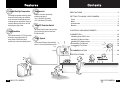
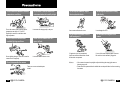
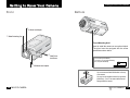
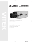
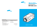
B W CCD CAMERA
INSTRUCTION MANUAL
BW-4302 SERIES
[ SALES NETWORK ]
・SAMSUNG TECHWIN CO., LTD
・SAMSUNG OPTO-ELECTRONICS AMERICA INC.
40 SEAVIEW DIRVE, SECAUCUS N.J
OPTICS & DIGITAL IMAGING DIV.
145-3, SANGDAEWON 1-DONG, JUNGWON-GU, 07094, U.S.A.
SUNGNAM, KYUNGKI-DO, KOREA
TEL : 209-902-0347
462-121
FAX : 201-902-9342
TEL : 82 -031-740 - 8137~41
FAX: 82 -031-740 - 8145
P/ NO. : 6806-0344-01A
・www.samsungcamerausa.com
Printed in Korea
・www.samsungtechwin.com
crecom 01.11
・www.samsungcctv.co.kr
SAMSUNG CCD CAMERA
Thank you for purchasing a SAMSUNG CCD CAMERA.
Before operating the camera, confirm the camera model and
proper input power voltage. In order that you can understand this
manual thoroughly, we'll introduce our model description.
BW-4302 Series
• EIA models
BW-4302EA
• CCIR models
BW-4302CA
BW-4302CH
Model Description
BW-4302 x x
power source
signal system
• Signal System
E
EIA Model
C
CCIR Model
• Power Source
A
AC 24V ~
DC 12V
D
H
High Voltage (CCIR Model: AC 230V~ )
2 B W CCD CAMERA
B W CCD CAMERA
3
CAUTION
RISK OF ELECTRIC SHOCK
DO NOT OPEN
WARNING- TO PREVENT RISK OF FIRE OR ELECTRIC SHOCK,
DO NOT EXPOSE THIS CAMERA TO RAIN OR MOISTURE.
CAUTION :
TO REDUCE THE RISK OF ELECTRIC SHOCK,
DO NOT REMOVE COVER (OR BACK),
NO USER SERVICEABLE PARTS INSIDE.
REFER SERVICING TO QUALIFIED
SERVICE PERSONNEL.
The lightning flash with arrowhead symbol, within
an equilateral triangle is intended to alert the user to
the presence of uninsulated "dangerous voltage"
within the product's enclosure that may be of
sufficient magnitude to constitute a risk of electric
shock to persons.
The exclamation point within an equilateral triangle
is intended to alert the user to the presence of
important operating and maintenance (servicing)
instructions in the literature accompanying the
appliance.
INFORMATION -This equipment has been tested and found to
comply with limits for a Class A digital device, pursuant to part
15 of the FCC Rules. These limits are designed to provide
reasonable protection against harmful interference when the
equipment is operated in a commercial environment. This
equipment generates, uses, and can radiate radio frequency
energy and, if not installed and used in accordance with the
instruction manual, may cause harmful interference to radio
communications.
Operation of this equipment in a residential area is likely to
cause harmful interference in which case the user will required
to correct the interference at his own expense.
WARNING - Changes or modifications not expressly approved
by the manufacturer could void the user’s authority to operate
the equipment.
CAUTION : To prevent electric shock and risk of fire hazards:
Do NOT use other than specified power source.
Do NOT expose this appliance to rain or moisture.
This installation should be made by a qualified service
person and should conform to all local codes.
4 B W CCD CAMERA
B W CCD CAMERA
5
Features
Automatic Backlight Compensation
Electronic Iris
The backlight compensation technology allows
the camera to find the best picture conditions
in any environment and automatically gives a
necessary light level compensation, so that you
can always obtain the clear picture, the finest
detail and perfect light contrast.
Electronic iris shutter is automatically
controlled at the speed of
1/60~1/100,000sec (EIA models),
1/50~1/100,000sec (CCIR models).
High Resolution
The horizontal resolution of 570 TV lines can be
achieved by using a high density CCD
having effective 410,000 pixels, which
provides clean, noiseless and reliable pictures.
Video/DC Selection Switch
The camera accepts 2 types of auto lris lenses
(DC type/Video type) and is set with Video/
DC selection switch.
SYNC. System
You can select INT(Internal Synchronization)
mode or L. L(Linelock Synchronization) mode.
Contents
PRECAUTIONS ........................................................................ 6
GETTING TO KNOW YOUR CAMERA..................................... 7
Front ....................................................................................... 7
Back ........................................................................................ 8
Accessories ............................................................................ 9
Bottom .................................................................................... 10
CONTROLS AND ADJUSTMENTS........................................... 11
CONNECTION .......................................................................... 14
Installing Auto IRIS Lens ........................................................ 14
Installing C-Mount Lens .......................................................... 16
Installing CS-Mount Lens ........................................................ 17
Connecting To Monitor ........................................................... 18
Connecting To Power ............................................................. 19
TROUBLESHOOTING .............................................................. 20
SPECIFICATIONS .................................................................... 21
6 B&W CCD CAMERA
B W CCD CAMERA
7
Precautions
Do not install the camera in extreme
temperature conditions.
Do use the camera under conditions where
temperatures are within -10°C to 50°C.
Especially be careful for ventilation under
high temperature.
Do not install or use the camera in an
environment where the humidity is high.
It can cause the image quality to be poor.
Do not drop the camera or subject
them to physical shocks.
It can cause malfunctions to occur.
Do not expose the camera to rain or
spill beverage on it.
Do not install the camera under
unstable lighting conditions.
Never keep the camera face to strong
light directly.
It can damage the CCD.
Do not touch the front glass of the
camera.
Never use the camera close to a
gas or oil leak.
Severe lighting change or flicker can cause the
camera to work improperly.
It can cause malfunctions to occur.
Do not disassemble the camera.
If it gets wet, wipe it dry immediately.
Liquids can contain minerals that corrode
the electronic components.
Notes:
It is one of the most important parts of camera.
Be careful not to be stained by fingerprint.
•If the camera is exposed to spotlight or object reflecting the strong light, smear or
blooming may occur.
There are no user-serviceable parts
inside it.
8 B W CCD CAMERA
•Please check the power whether it satisfies the normal specification before connecting
the camera.
B W CCD CAMERA
9
Getting to Know Your Camera
Front
Getting to Know Your Camera
Bottom
C -Mount Lens Adapter
Glass Protecting Cap
Tripod Mounting Hold
Used to install the camera on an optional tripod.
The tripod must be equipped with the screw
specified as shown below
Back Focus
Lock Screw
1/4″-20 UNC (20 THREAD)
L : 4.5mm ± 0.2 mm (ISO standard),
or 0.197″(ASA standard)
L
CS-Mount Lens Adapter
You can remove and install this bracket on the top
of the camera.
You must use the supplied screw or the equivalent
(within 5mm). If not, it can cause malfunction and
demage inside the camera.
10 B&W CCD CAMERA
B W CCD CAMERA
11
Getting to Know Your Camera
Getting to Know Your Camera
Back
Accessories
IRIS Mode
Selection Switch.
Video Out Jack
IRIS lens plug
BLC Function select Switch
Auto Iris Lens Connector
LEVEL Adjustment V.R
(Using DC Iris Lens Only!)
SYNC Mode selection switch
Notes:There is no Sync selection
switch on the rear of DC
power type.
L-Wrench
Power Input Terminal
Notes: Each model has the different
power source.
V.PHASE Adjustment V.R
Notes: There is no V.PHASE VR
on the rear of DC power type.
Instruction
Manual
High Voltage type
(4302CH)
12 B W CCD CAMERA
B W CCD CAMERA
13
Controls and Adjustments
Controls and Adjustments
Glass Protecting Cap
Be sure to cap the lens mount when the lens is not mounted. Pull out the
cap to remove.
C-Mount Lens Adapter
Used to mount a C-mount lens. Remove it to mount a CS-mount lens. Turn
counterclockwise to remove.
CS-Mount Lens Adapter
Used to mount a CS-mount lens. C-mount lenses can be used when the
C-mount adapter is attached, and CS-mount lenses can be used when it is
removed.
Back Focus Lock Screw
Used to readjust backfocus of the camera. There are two backfocus lock
screws. These must be loosened before the camera may be back
focused. Loosen lock screw using the L-wrench to turn the CS-mount lens
adapter, and tighten the lock screw after adjustment.
Tripod Mounting Hole
This screw hole is used to install the camera on a mount. The camera can
be installed on a tripod or other camera mount either from the top or the
bottom by using the 1/4” - 20UNC threaded holes in the camera. For
details, see page 11.
Video Out Jack
Connect to the video input connector of monitor. This jack outputs a
composite video signal. Use a coaxial cable for connection.
Auto lris Lens Connector
Used to connect auto iris lens plug. Be sure to use video-drive auto iris
lens that operates on DC 12V and requires 40 mA or less. For details, see
page 18.
14 B W CCD CAMERA
SYNC Mode Selection Switch
Used to choose INT or LL mode.
SYNC (Synchronization) Mode
INT(Internal) mode : The camera may be operated independently with its
internal crystal control.
LL(Linelock) mode : It synchronizes the video signal between cameras using
the frequency of the AC power supply without external
synchronous generator.
Notes :
The LL mode can be used in the areas of 60Hz(EIA models) and
50Hz(CCIR models).
There is no SYNC selection switch on the rear of DC power type.
V. PHASE Adjustment V. R
If camera is to be used in the LL mode, the vertical phase may require
adjustment to synchronize the vertical phase of the camera with other
camera in the system.
Make this adjustment when the vertical phase of the camera does not
match with other cameras or systems. For correct adjustment, use a multichannel oscilloscope. The V adjustment has been set at 180 degrees
and can be readjusted in the range of 0 to 270 degrees.
Notes :
This adjustment is necessary only when line lock sync operation is
performed.
There is no V. PHASE V.R on the rear of the DC power type.
Power Input Terminal
Used to connect AC/DC power source. For details, see page 23.
Notes : Each model has the different power source, you must confirm
appropriate power source of your camera.
Level Adjustment V. R (Using DC Iris Lens Only!)
Used to adjust video output level. When the brightness control of the
monitor does not operate correctly, you can get the optimum picture by
controlling the Video output level of camera.
B W CCD CAMERA
15
Controls and Adjustments
Monitor picture
To make it brighter
To make it darker
Adjustment direction
Turn clockwise
Turn counterclockwise
Notes : This function is activated when being in the ESC mode.
BLC(Backlight Compensation) Function CENTER/FULL Switch
This switch improves an image that is darkened because of backlighting.
This Function be possible only when the camera have a manual lens.
When the lighting source is in the rear of object, the object might be
seen some darkness. If you want to see object clearly, turn this switch
Center or Full the following diagram:
Center emphasis
MANUAL LENS
When manual lens is mounted, two modes are available.
In VIDEO or DC mode, electronic shutter is fixed in “1/60” sec(EIA models),
“1/50” sec(CCIR models).
In ESC mode, electronic shutter is automatically controls the shutter speed
from “1/60” to “1/100,000” sec(EIA models), “1/50” to “1/100,000” sec(CCIR
models).
Notes : ESC (Electronic Shutter Control)mode : Electronically controls
optimal shutter speed.
Full emphasis
IRIS Mode Selection Switch
Used to choose DC/VIDEO or ESC mode according to the type of your
lens.
USING AUTO IRIS LENS
You can choose DC or VIDEO mode according to the type of the lens.
In this case, electronic shutter is fixed in “1/60” sec(EIA models),
“1/50”sec(CCIR models).
16 B W CCD CAMERA
B&W CCD CAMERA
17
Connection
Lens
Lens is not supplied with this camera. Purchase a lens suitable for
your environment. This camera accepts auto iris lens, both C- and
CS-mount lens.
Notes:
If the lens is stained with fingerprint or something, the image quality
might be poor.
It is recommended to use a high quality lens to improve the image
quality under low illumination.
CONNECTION
3. Remove the cover from the connector pin supplied, and
solder the lens cable to the connector pin as shown
below.
• Video type :
No. 1 Pin --- Red (Power source, DC 12V, 40mA MAX)
No. 2 Pin --- N.C
No. 3 Pin --- White (Video signal)
No. 4 Pin --- Black (GND)
• DC type :
No. 1 Pin --- Damping No. 2 Pin --- Damping +
No. 3 Pin --- Drive +
No. 4 Pin --- Drive -
Installing Auto Iris Lens
Cover
Lens cable
1. Peel the end of lens cable outer cover approximately 8mm. (5/16inch)
approx.
8 mm(5/16inch)
No. 3 Pin
No. 1 Pin
No. 4 Pin
No. 2 Pin
connector
4. Remove the protecting cap, and attach the lens into the
camera by turning clockwise.
2. Peel the end of the cable inner cover approximately 2mm. (1/16inch)
approx.
2 mm(1/16inch)
18 B W CCD CAMERA
B W CCD CAMERA
19
CONNECTION
CONNECTION
5. Connect the lens plug to the auto iris connector on the
rear of the camera.
Installing CS-Mount lens
1. Remove the protecting cap and C-mount adapter.
6. Set the IRIS Mode selection switch to Video according
to the type of the lens.
C-Mount Lens Adapter.
Glass Protecting Cap.
2. Attach the lens into the camera by turning clockwise.
Installing C-Mount lens
After removing the protecting cap, attach the lens into the
camera by turning clockwise.
C-Mount Lens Adapter.
20 B W CCD CAMERA
Notes:
• Use the lens under the specification aside.
• Otherwise the lens can damage the camera
or abnormal fixing may be resulted in.
• A heavy lens may disturb the balance with
C-mount lens : 14 mm or less
the camera and possibly results in damage.
CS-mount lens : 9 mm or less
Don't use more than 450g lens.
• It is recommended to set the lens ALC mode to Av mode
(Average). Pk mode can be occurred hunting.
B W CCD CAMERA
21
CONNECTION
CONNECTION
Connecting to Power
Connecting to Monitor
Connect the VIDEO out jack to the monitor video in jack.
Each model has the different power source and the operation
characteristics.
Make sure the power is supplied to the appropriate power terminals
on the camera. Connect the power as referred on the following
figures.
Monitor
CCD Camera
AC24V, 60Hz : BW-4302EA
AC24V, 50Hz : BW-4302CA
• As a connecting method varies according to instruments,
refer to the manual supplied with the instrument.
• Connect the cable after power is turned off.
• Set the 75Ω/Hi-Z selection switch as shown below if you
have intermediate device.
AC230V , 50Hz : BW-4302CH
Intermediate
VIDEO
75
VIDEO
Hi-Z
75
Hi-Z
Notes:
IN
OUT
IN
OUT
• Be sure to connect power cord after you finish installation.
• Check whether the frequency of power is 60Hz to use the linelock(L.L) mode in EIA models.
CCD Camera
22 B W CCD CAMERA
End monitor
• Check whether the frequency of power is 50Hz to use the linelock(L.L) mode in CCIR models.
B W CCD CAMERA
23
Specifications
Troubleshooting
If you have trouble operating your camera, refer to the following. If
the guidelines do not enable you to solve the problem, contact an
authorized technician.
Problem
Nothing appears
on the screen.
Solution
• Check that the power cord and line connection
between the camera and monitor are made properly.
• Check that the VIDEO/ESC selection switch on the
rear of the camera set to a proper position according
to the type of your lens.
The image on the • Check if the lens are stained. If dirty, clean the lens
with soft, clean cloth.
screen is dim.
The camera is
• Check that you have connected the camera to a
proper power.
not work
properly, and the
– AC 24V, 60Hz
: BW-4302EA
surface of the
– AC 24V ~, 50Hz
: BW-4302CA
camera case is
– AC 230V ~, 50Hz
: BW-4302CH
hot.
The contrast on
the screen is too
weak.
• Adjust the contrast feature of the monitor. If the
camera is exposed under too strong light, change the
camera position.
The image on the • Does the camera face to directly to the sun or
screen flickers.
fluorescent lighting? Change the camera position.
ITEM
BW-4302EA
BW-4302CA
BW-4302CH
POWER SOURCE
AC24V, 60Hz
AC24V, 50Hz
AC230V, 50Hz
POWER CONSUMPTION
4W
4W
4W
SYNC. SYSTEM
INT/Linelock
seclectable
(Phase: 0~270
Power frequency:
60Hz only)
INT/Linelock seclectable
(Phase: 0~270 Power frequency:
50Hz only)
PICK-UP DEVICE
768(H) 582(V)1/3” BW CCD
752(H) 582(V)1/3” BW CCD
SCANNING SYSTEM
2:1 Interlace
525Lines
2:1 Interlace
625Lines
0.05 Lux at F1.2
MINIMUM ILLUMINATION
RESOLUTION
VIDEO OUTPUT
570(H)TV Lines
1.0 Vp-p EIA Comp.
1.0 Vp-p CCIR Comp.
Backlight Compensation
Center/Full Selectable
IRIS MODE
VIDEO/ESC/DC Selectable
ELECTRONIC IRIS
1/60~1/100,000 Sec
LENS
C/CS MOUNT Changeable
GAMMA CORRECTION
0.45
AGC
Built-in 28dB
APERTURE CORRECTION
Built-in
50dB
S/N RATIO
The image on the • Check that you have used 50Hz (CCIR models) and
60Hz (EIA models) in linelock (L.L) mode. If the power
screen is
frequency is out of 50Hz (CCIR models)
distorted.
/60Hz (EIA models), the linelock(L.L) synchronization
mode cannot be used. Use the Synchronization Mode
to INT mode.
24 B W CCD CAMERA
AMBIENT TEMPERATURE
DIMENSION
-10
+50
55(W) 57(H)
14
122
136(L)mm(Without Lens)
WEIGHT
440g(Without Lens) 450g(Without Lens) 500g(Without Lens)
ACCESSORY
IRIS JACK, MANUAL, L-WRENCH
B W CCD CAMERA
25
MEMO
DECLARATION OF CONFORMITY
Application of Council Directive(s)
Manufacturer's Name
Manufacturer's Address
European Representative Name
European Representative Address
Equipment Type/Environment
Model Name
Beginning Serial NO.
Year of Manufacture
Conformance to
89/336/EEC
SAMSUNG TECHWIN CO., LTD
SAMSUNG TECHWIN CO., LTD
42, SUNGJU-DONG CHANGWON-CITY,
KYUNGNAM, KOREA, 641-120
Black & White CCD CAMERA
BW-4302CA/BW-4302CH
M1120001
2001
EN 60065
EN 55 013
EN 50 082-1
We, the undersigned, hereby declare that the equipment specified above
conforms to the above Directive(s).
Manufacturer
SAMSUNG TECHWIN CO., LTD
Legal Representative in Europe
Full Name
YOUNG TAEK SON
Full Name
Position
QUALITY CONTROL MANAGER
Position
Place
CHANGWON, KOREA
Place
Date
2001. 12. 1
Date
Signature
Signature
26 B W CCD CAMERA