1
smartCore Express SMA200 BIOS
BIOS, Driver & Software Information
Document Revision 102
If it's embedded, it's Kontron.
» Table of Contents «
1
User Information............................................................................ 4
1.1
About this Document ...............................................................................................................4
1.2
Copyright Notice .....................................................................................................................4
1.3
Trademarks ............................................................................................................................4
1.4
Standards..............................................................................................................................4
1.5
Warranty ...............................................................................................................................4
1.6
Technical Support ...................................................................................................................5
1.7
Environmental Protection Statement ...........................................................................................5
1.8
RoHS Commitment ..................................................................................................................5
1.8.1
RoHS Compatible Product Design...............................................................................................6
1.8.2
RoHS Compliant Production Process ...........................................................................................6
1.8.3
WEEE Application ...................................................................................................................6
1.9
Swiss Quality ..........................................................................................................................6
1.10
The Swiss Association for Quality and Management Systems..............................................................7
2
Introduction ................................................................................. 8
2.1
Standard Features ...................................................................................................................8
2.2
Incompatibilities ....................................................................................................................8
3
Operating Systems Compatibility........................................................ 9
3.1
Microsoft Windows ..................................................................................................................9
3.2
Microsoft Windows XPe .............................................................................................................9
3.3
Microsoft Windows CE...............................................................................................................9
3.3.1
CE4.2 / CE5.0 ........................................................................................................................9
3.3.2
CE6.0 ..................................................................................................................................9
3.4
Linux.................................................................................................................................. 10
3.4.1
SLAX ................................................................................................................................. 10
3.4.2
ELinOS............................................................................................................................... 10
3.4.3
What is ELinOS? ................................................................................................................... 10
3.5
Real-time OS ........................................................................................................................ 10
3.5.1
QNX .................................................................................................................................. 10
3.5.2
VxWorks ............................................................................................................................. 10
www.kontron.com
4
Driver Installation .........................................................................11
4.1
Windows 2000 & XP ............................................................................................................... 11
4.1.1
Chipset .............................................................................................................................. 12
4.1.2
VGA................................................................................................................................... 12
4.1.3
LAN................................................................................................................................... 13
4.1.4
AC97-Sound........................................................................................................................ 14
4.1.5
RAID ................................................................................................................................. 14
4.2
Display Driver and Control Panel ............................................................................................... 17
4.3
AC97 Sound Driver and Control Panel......................................................................................... 19
4.4
SpeedStep ........................................................................................................................... 20
4.5
SpeedStep Performance Control ............................................................................................... 20
4.5.1
Set up Power Management ..................................................................................................... 21
5
The Special Function Interface (SFI) ..................................................22
5.1
INT15h SFR Functions............................................................................................................. 22
5.2
Int15 Emulator Driver for Windows ............................................................................................ 24
5.2.1
Int15 Hardware ................................................................................................................... 24
5.2.2
Int15 Windows Software ........................................................................................................ 25
5.2.3
Driver Installation W2k/XP ..................................................................................................... 25
5.2.4
Driver Installation Windows-NT ............................................................................................... 26
5.2.5
Programming Int15dl Interface under Windows .......................................................................... 26
6
Software......................................................................................28
6.1
Windows Int15 Tool ............................................................................................................... 28
6.2
Int15 Windows Software ......................................................................................................... 28
7
Diagnostics ..................................................................................29
7.1
Phoenix SecureCore™ Checkpoint Lists for the SMA200.................................................................. 29
7.1.1
POST Code Checkpoints.......................................................................................................... 29
8
BIOS...........................................................................................32
8.1
BIOS History ........................................................................................................................ 32
8.2
Specifications of the BIOS ....................................................................................................... 33
8.3
Core BIOS Functions .............................................................................................................. 34
8.4
Core BIOS Download .............................................................................................................. 36
8.5
BIOS Setup .......................................................................................................................... 37
8.5.1
Main Menu.......................................................................................................................... 37
www.kontron.com
8.5.2
Advanced ........................................................................................................................... 38
8.5.3
Advanced I/O Configuration ................................................................................................... 38
8.5.4
Advanced Console Redirection ................................................................................................ 39
8.5.5
Intel ................................................................................................................................. 39
8.5.6
Intel CPU Control ................................................................................................................. 40
8.5.7
Intel CPU Thermal Control ...................................................................................................... 40
8.5.8
Intel Poulsbo Control ............................................................................................................ 41
8.5.9
Intel Poulsbo PCI Express Control ............................................................................................ 41
8.5.10 Intel Poulsbo USB Control ...................................................................................................... 42
8.5.11 Intel Video Control ............................................................................................................... 42
8.5.12 Security ............................................................................................................................. 43
8.5.13 Boot.................................................................................................................................. 43
8.5.14 Exit ................................................................................................................................... 44
8.6
CMOS RAM Map ..................................................................................................................... 45
9
Appendix A: Document Revision History .............................................50
10
Index..........................................................................................51
www.kontron.com
smartCore Express SMA200 BIOS / User Information
1
User Information
1.1
About this Document
This document provides information about products from Kontron AG and/or its subsidiaries. No warranty of
suitability, purpose, or fitness is implied. While every attempt has been made to ensure that the information in this
document is accurate, the information contained within is supplied "as-is" and is subject to change without notice.
For the circuits, descriptions and tables indicated, Kontron assumes no responsibility as far as patents or other rights
of third parties are concerned.
1.2
Copyright Notice
Copyright© 2003-2010 Kontron AG
All rights reserved. No part of this document may be reproduced, transmitted, transcribed, stored in a retrieval
system, or translated into any language or computer language, in any form or by any means (electronic, mechanical,
photocopying, recording, or otherwise), without the express written permission of Kontron AG.
1.3
Trademarks
MICROSPACE®, smartModule®, smartCore®Express and DIGITAL-LOGIC® are trademarks or registered trademarks of
Kontron Compact Computers AG. Kontron is a trademark or registered trademark of Kontron AG.
The following lists some of the trademarks of components used in this product.
» IBM, XT, AT, PS/2 and Personal System/2 are trademarks of International Business Machines Corp.
» Microsoft is a registered trademark of Microsoft Corp.
» Intel is a registered trademark of Intel Corp.
All other products and trademarks mentioned in this manual are trademarks of their respective owners.
1.4
Standards
Kontron AG is certified to ISO 9000 standards.
1.5
Warranty
This Kontron AG product is warranted against defects in material and workmanship for the warranty period from the
date of shipment. During the warranty period, Kontron AG will, at its discretion, decide to repair or replace defective
products.
Within the warranty period, the repair of products is free of charge as long as warranty conditions are observed.
The warranty does not apply to defects resulting from improper or inadequate maintenance or handling by the buyer,
unauthorized modification or misuse, operation outside of the product’s environmental specifications or improper
installation or maintenance.
Kontron AG will not be responsible for any defects or damages to other products not supplied by Kontron AG that are
caused by a faulty Kontron AG product.
4
www.kontron.com
smartCore Express SMA200 BIOS / User Information
1.6
Technical Support
Technicians and engineers from Kontron AG and/or its subsidiaries are available for technical support. We are
committed to making our products easy to use and will help you use our products in your systems.
Please consult our website at http://www.kcc-ag.ch/index.php?id=products-download for the latest product
documentation, BIOS, drivers, tools and software information.
For technical support consult http://support.kcc-ag.ch/ .
1.7
Environmental Protection Statement
This product has been manufactured to satisfy environmental protection requirements wherever possible. Many of the
components used (structural parts, printed circuit boards, connectors, batteries, etc.) are capable of being recycled.
Final disposal of this product after its service life must be accomplished in accordance with applicable country, state,
or local laws or regulations. All components within this product fulfill the requirements of the RoHS (Restriction of
Hazardous Substances Directive). The product is soldered with a lead free process.
1.8
RoHS Commitment
Kontron Compact Computers AG (Switzerland) is committed to develop and produce environmentally friendly products
according to the Restriction of Hazardous Substances (RoHS) Directive (2002/95/EC) and the Waste Electrical and
Electronic Equipment (WEEE) Directive (2002/96/EC) established by the European Union. The RoHS directive was
adopted in February 2003 by the European Union and came into effect on July 1, 2006. It is not a law but a directive,
which restricts the use of six hazardous materials in the manufacturing of various types of electronic and electrical
equipment. It is closely linked with the Waste Electrical and Electronic Equipment Directive (WEEE) 2002/96/EC,
which has set targets for collection, recycling and recovery of electrical goods and is part of a legislative initiative to
solve the problem of huge amounts of toxic e-waste.
Each European Union member state is adopting its own enforcement and implementation policies using the directive
as a guide. Therefore, there could be as many different versions of the law as there are states in the EU. Additionally,
non-EU countries like China, Japan, or states in the U.S. such as California may have their own regulations for green
products, which are similar, but not identical, to the RoHS directive.
RoHS is often referred to as the "lead-free" directive but it restricts the use of the following substances:
» Lead
» Mercury
» Cadmium
» Chromium VI
» PBB and PBDE
The maximum allowable concentration of any of the above mentioned substances is 0.1% (except for Cadmium, which
is limited to 0.01%) by weight of homogeneous material. This means that the limits do not apply to the weight of the
finished product, or even to a component but to any single substance that could (theoretically) be separated
mechanically.
5
www.kontron.com
smartCore Express SMA200 BIOS / User Information
1.8.1 RoHS Compatible Product Design
All standard products from Kontron Compact Computers (KCC) comply with RoHS legislation.
Since July 1, 2006, there has been a strict adherence to the use of RoHS compliant electronic and mechanical
components during the design-in phase of all KCC standard products.
1.8.2 RoHS Compliant Production Process
KCC selects external suppliers that are capable of producing RoHS compliant devices verified by:
» A confirmation from the supplier indicating that their production processes and resulting devices are RoHS
compliant.
» If there is any doubt of the RoHS compliancy, the concentration of the previously mentioned substances in a
produced device will be measured. These measurements are carried out by an accredited laboratory.
1.8.3 WEEE Application
The WEEE directive is closely related to the RoHS directive and applies to the following devices:
» Large and small household appliances
» IT equipment
» Telecommunications equipment (although infrastructure equipment is exempt in some countries)
» Consumer equipment
» Lighting equipment – including light bulbs
» Electronic and electrical tools
» Toys, leisure and sports equipment
» Automatic dispensers
It does not apply to fixed industrial plants and tools. The compliance is the responsibility of the company that brings
the product to market, as defined in the directive. Components and sub-assemblies are not subject to product
compliance. In other words, since Kontron Compact Computers AG does not deliver ready-made products to end users
the WEEE directive is not applicable for KCC. Users are nevertheless encouraged to properly recycle all electronic
products that have reached the end of their life cycle.
1.9
Swiss Quality
» 100% Made in Switzerland
» This product was not manufactured by employees earning piecework wages
» This product was manufactured in humane work conditions
» All employees who worked on this product are paid customary Swiss market wages and are insured
» ISO 9000:2001 (quality management system)
6
www.kontron.com
smartCore Express SMA200 BIOS / User Information
1.10 The Swiss Association for Quality and Management Systems
The Swiss Association for Quality and Management Systems (SQS) provides certification and assessment services for
all types of industries and services. SQS certificates are accepted worldwide thanks to accreditation by the Swiss
Accreditation Service (SAS), active membership in the International Certification Network, IQNet, and co-operation
contracts/agreements with accredited partners.
www.sqs.ch
The SQS Certificate ISO 9001:2000 has been issued to Kontron Compact Computers AG in the field of development,
manufacturing and sales of embedded computer boards, embedded computer modules and computer systems. The
certification is valid for three years at which time an audit is performed for recertification.
7
www.kontron.com
smartCore Express SMA200 BIOS / Introduction
2
Introduction
The smartCoreExpress SMA200 BIOS is used on Kontron Compact Computers' (KCC) 200 series of products.
2.1
Standard Features
» Phoenix SecureCore BIOS ROM
2.2
Incompatibilities
t.b.d.**
8
www.kontron.com
smartCore Express SMA200 BIOS / Operating Systems Compatibility
3
Operating Systems Compatibility
3.1
Microsoft Windows
Kontron Compact Computers (KCC) recommends the following Windows operating systems in combination with the
chipset listed below:
» Intel A200:
Windows Vista, Windows XP (SP2)
It is not recommended to install an older Windows OS, such as Windows 95/98/ME/NT4/2K, because of incomplete
driver support from the chip manufacturer.
3.2
Microsoft Windows XPe
KCC provides a Windows XPe (SP2) Board Support Package for the following chipset:
Intel A200:
http://www.kcc-ag.ch/index.php?id=294&dir=BSP/INTELA200&mountpoint=46
A CompactFlash with a copy of "Evaluation Windows XPe" pre-installed can be ordered for testing purposes:
» Intel A200
3.3
Article number 816060
Microsoft Windows CE
3.3.1 CE4.2 / CE5.0
KCC works in cooperation with Pfaadtsoft and therefore recommends using the WINCE 4.2/5.0 Board Support Package
(BSP) developed especially for this product.
There are also DEMO Windows CE 4.2 / 5.0 images available for free at:
http://dlag.pfaadtsoft.de/
3.3.2 CE6.0
Kontron Compact Computers provides a Windows CE 6.0 BSP for the following chipset:
Intel A200:
http://www.kcc-ag.ch/index.php?id=294&filename=CE6.zip&dir=BSP/A200&task=download&mountpoint=46
You can order a CompactFlash with a pre-installed copy of "Evaluation Windows CE6" for testing purposes.
» Intel A200
9
Article number 816070
www.kontron.com
smartCore Express SMA200 BIOS / Operating Systems Compatibility
3.4
Linux
3.4.1 SLAX
Kontron Compact Computers (KCC) provides a Linux distribution (Kernel 2.6.24) for the following chipsets:
AMD LX800, Intel 855, Intel 945, Intel A200
Follow this link to download the BSP / Demo SLAX Linux:
http://www.kcc-ag.ch/index.php?id=294&dir=BSP/SLAX-BSP&mountpoint=46
A CompactFlash with a pre-installed copy of Linux for testing purposes can be ordered:
» Linux
Article Number 816030
The distribution is based on the SLAX Linux. For more information, updates and plug-ins, visit:
www.slax.org
3.4.2 ELinOS
KCC works in cooperation with SYSGO and therefore recommends using the ELinOS Linux distribution.
http://www.elinos.com/
SYSGO has developed a board support package (BSP) for the Pentium M and the Pentium BX/TX chipset-based
products for ELinOS. If you are interested or if you have any questions about ELinOS, please contact SYSGO directly.
3.4.3 What is ELinOS?
ELinOS is a development environment based on Linux for the creation of embedded systems for intelligent devices.
With ELinOS the memory demand of Linux is reduced to less than 1MB ROM and 2MB RAM. In this manner Linux can,
for the first time, conform to the reduced hardware conditions of embedded systems. Even in this basic configuration,
Linux offers largely the same functionality which made it so popular in the server and desktop field. By virtue of access
to the constantly growing number of Linux components, the basic system can be expanded at any time.
The core of ELinOS is a Linux distribution custom-tailored to the embedded systems currently sold. Besides the wellknown Linux version for x86, ELinOS also supports PowerPC-, ARM-, MIPS-, and SH3-platforms which are very popular
in the embedded field.
The emphasis of the current version of ELinOS is on the new CoTools, CODEO and COGNITO. CODEO is Eclipse based and
provides additional plug-ins for project management and target communication, which substantially improves the
ease of development of applications with ELinOS. COGNITO is a further integrated tool for the analysis of system
performance. It permits the collection, recording and display of all system information and facilitates the fast
optimization of software for intelligent devices.
ELinOS has been updated to the new version of the GNU tool chain and contains the stable Linux Kernel starting with
version 2.4.25; it has integration of Java and the real-time extensions RTAI 3.0 for hard real-time requirements. The
package is complemented with Carrier Grade Extensions such as IPv6, IPSec, SNMP, etc., for the use of Linux in
applications in the telecommunications market.
3.5
Real-time OS
3.5.1 QNX
Download a demo image from the following website:
https://www.qnx.com/account/Login.html?logout=1
3.5.2 VxWorks
Please contact Wind River for VxWorks support:
10
www.windriver.com
www.kontron.com
smartCore Express SMA200 BIOS / Driver Installation
4
Driver Installation
4.1
Windows 2000 & XP
On the Product CD you will find all the tools and drivers you’ll need to work with the product. If you are unsure how
current your software is, please visit our website to get the latest releases!
http://www.kcc-ag.ch/index.php?id=products-download
A correct installation of Windows is required for the following steps.
11
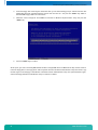
1.
Close all applications before beginning with the driver installation!
2.
Put the Kontron Compact Computers Product CD into the CD-drive. The start menu should appear
automatically.
3.
Select: Drivers/WinXP.
If there is no menu then manually open up the CD on the desktop.
www.kontron.com
smartCore Express SMA200 BIOS / Driver Installation
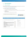
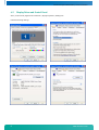
4.1.1 Chipset
Driver: x:\drivers\SMA200\chipset\
Double click on setup.exe and follow the instructions:
Reboot the system after installation.
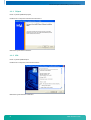
4.1.2 VGA
Driver: x:\drivers\SMA200\VGA
Double click on setup.exe; follow the instructions:
Reboot the system after the installation.
12
www.kontron.com
smartCore Express SMA200 BIOS / Driver Installation
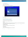
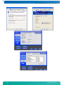
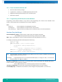
4.1.3 LAN
Driver: x:\drivers\SMA200\Ethernet
Double click on setup.exe and follow the instructions:
Or double click on autorun.exe and follow the instructions:
Click "Install Drivers".
13
www.kontron.com
smartCore Express SMA200 BIOS / Driver Installation
4.1.4 AC97-Sound
Driver: x:\drivers\SMA200\Audio
Double click on setup.exe and follow the instructions:
4.1.5 RAID
Raid is not supported on the SMA200
Loading the driver during OS installation
Overview
The Silicon Image SATA driver must be loaded during the operating system installation using the F6 installation
method in order to install an operating system onto a hard drive.
F6 installation method
The F6 installation method requires a floppy with the driver files.
F6 floppy driver:
Driver: x:\drivers\SMA200\SATA\3132_x86_1.0.22.0_logo.zip
14
www.kontron.com
smartCore Express SMA200 BIOS / Driver Installation
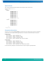
F6 Installation Steps
To install the Intel® Matrix Storage Manager driver using the F6 installation method, complete the following steps:
1.
Note
2.
15
Press the <F6> key at the beginning of the Windows XP setup (during the text-mode phase) when prompted
in the status line with the "Press F6 if you need to install a third party SCSI or RAID driver" message.
After pressing F6, nothing will happen immediately; setup will temporarily continue loading drivers and then
you will be prompted with a screen to load support for mass storage device(s).
Press the <Z> key to specify an additional device.
www.kontron.com
smartCore Express SMA200 BIOS / Driver Installation
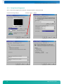
3.
Insert the floppy disk containing the driver files when you see the following prompt: "Please insert the disk
labeled Manufacturer-supplied hardware support disk into Drive A:" and press the <Enter> key. Refer to
Automatic F6 Floppy Creation for instructions.
4.
Select the "Silicon Image SiI 3132 SATALink Controller for Windows XP/Server2003" entry and press the
<Enter> key.
5.
Press the <Enter> key to confirm.
At this point, you have successfully F6 installed the Silicon Image SATA driver and Windows XP setup should continue.
Leave the floppy disk in the floppy drive until the system reboots itself because the Windows setup will need to copy
the files again from the floppy to the Windows installation folders. After Windows setup has copied these files again,
remove the floppy diskette so that Windows setup can reboot as needed.
16
www.kontron.com
smartCore Express SMA200 BIOS / Driver Installation
4.2
Display Driver and Control Panel
Start / Control Panel / Appearance and Themes / Display Properties / Settings tab
Enter the following settings:
17
www.kontron.com
smartCore Express SMA200 BIOS / Driver Installation
18
www.kontron.com
smartCore Express SMA200 BIOS / Driver Installation
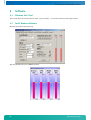
4.3
AC97 Sound Driver and Control Panel
Sound Settings:
19
www.kontron.com
smartCore Express SMA200 BIOS / Driver Installation
4.4
SpeedStep
4.5
SpeedStep Performance Control
The Pentium-M improved the SpeedStep mechanism by adding a third power scheme in addition to the low-power and
the full-performance modes. This new mode is called adaptive mode, and allows the frequency and voltage to switch
according to the CPU activity. The CPU uses a low-power mode by default, but when its activity increases, it switches
itself very quickly into full-performance mode. This new power scheme is very pleasant to use, because it allows full
CPU speed only when needed. Of course, power consumption depends on the CPU activity, and the more the CPU is
used, the more it consumes power.
Windows XP
Power Schemes
Home/Office Desktop
Portable/Laptop
Presentation
Always On
Minimal Power Management
Maximum Battery
AC Power
(Frequency example:
mobile Pentium-M 2 GHz)
None (2 GHz Always)
Adaptive (800 MHz <…>2 GHz
Adaptive (800 MHz <…>2 GHz
None (2 GHz Always)
Adaptive (800 MHz <…>2 GHz
Adaptive (800 MHz <…>2 GHz
Battery DC
(Frequency example:
mobile Pentium-M 1.6 GHz)
Adaptive (600 MHz <…>1.6 GHz
Adaptive (600 MHz <…>1.6 GHz
Degrade (600 MHz)
None (1.6 GHz Always)
Adaptive (600 MHz <…>1.6 GHz
Degrade (600 MHz)
CPU performance is heavily dependent on the choice of power scheme in the system control.
20
www.kontron.com
smartCore Express SMA200 BIOS / Driver Installation
4.5.1 Set up Power Management
Start / Control Panel / Appearance and Themes / Display Properties / Screen Saver tab
Enter the following settings:
21
click the "Power…" button
www.kontron.com
smartCore Express SMA200 BIOS / The Special Function Interface (SFI)
5
The Special Function Interface (SFI)
All functions are performed by starting the SW Interrupt 15hex with the following arguments:
5.1
INT15h SFR Functions
Function
WRITE TO EEPROM
Number
E0h
Description
Input values
AH
AL
BX
CL
SI
78h
E0h
Output value
Function
READ FROM EEPROM
Number
Description
E1h
Reads the data byte into the addressed User-Memory-Cell of the serial EEPROM.
DLAG Int15 function
Function request
Address in the EEPROM (0-1024 possible)
1234h User-Password (DLAG-Password for access to the DLAG-Memory-Cells)
Data byte
Output value
AH
AL
BX
SI
AL
Function
WRITE SERIAL NUMBER
Number
E2h
Input values
78h
E1h
Writes the data byte into the addressed User-Memory-Cell from the serial EEPROM. The old
value is automatically deleted.
DLAG Int15 function
Function request
Address in the EEPROM (0-1024 possible)
Data byte to store
1234h User-Password (otherwise EEP is write-protected)
None, all registers are restored when reopened.
Description
Input values
AH
AL
BX,
CX,
DX
SI
78h
E2h
Writes the serial number from the serial EEPROM into the addressed DLAG-Memory-Cell.
The old value is automatically deleted.
DLAG Int15 function
Function request
Serial number
Password
None, all registers are restored when reopened.
Output value
Function
READ SERIAL NUMBER
Number
Description
E3h
Input values
Output values
22
AH
AL
BX,
CX,
DX
78h
E3h
Reads the serial number from the board into the serial EEPROM.
DLAG Int15 function
Function request
Serial number (binary, not ASCI)
www.kontron.com
smartCore Express SMA200 BIOS / The Special Function Interface (SFI)
Function
WRITE PRODUCTION DATE
Number
E4h
Description
Input values
AH
AL
BX,
CX
CL
DI
SI
78h
E4h
Writes the production date into the addressed DLAG-Memory-Cell from the serial EEPROM.
The old value is automatically deleted. If the password is also in DX, the counters will be
reset (=0).
DLAG Int15 function
Function request
Production date
Day of month (1-31)
Password (clear counter)
Password
None, all registers are restored when reopened.
Output value
Function
READ PRODUCTION DATE
Number
Description
E5h
Input values
Output values
AH
AL
BX,
CX
78h
E5h
Reads the production date from the board in the serial EEPROM.
DLAG Int15 function
Function request
Production date
Function
WRITE INFO 2 TO THE EEPROM
Number
Description
E8h
AH
AL
SI
78h
E8h
DI
Input values
BH,
BL
CH,
CL
DH
DL
Writes the information bytes into the serial EEPROM.
DLAG Int15 function
Function request
Password
CPU type bits 1-7 and board type bits 8-15.
CPU type: 01h=ELAN300/310, 02h=ELAN400, 05h=P5, 08h=P3, 09h=ELAN520,
10h=P-M / BOARD TYPE
('M'=PC/104, 'E'=Euro, 'W'=MSWS, 'S'=Slot, 'C'=Custom, 'X'= smartCore or smartModule)
Board version (i.e., V1.5 BH=1, BL=5)
BIOS version (i.e., V3.0 CH=3, CL=0)
Number of 512K FLASH
Number of 512K SRAM
None, all registers are restored when reopened.
Output value
Function
READ INFO 2 FROM THE EEPROM
Number
Description
E9h
Input values
AH
AL
AL
DI
Output values
23
BH,
BL
CH,
CL
DH
DL
78h
E9h
Reads the information bytes out of the serial EEPROM.
DLAG Int15 function
Function request
Board type BOARD TYPE
('M'=PC/104, 'E'=Euro, 'W'=MSWS, 'S'=Slot, 'C'=Custom, 'X'= smartCore or smartModule)
CPU type bits 1-7 and board type bits 8-15.
CPU type: 01h=ELAN300/310, 02h=ELAN400, 05h=P5, 08h=P3, 09h=ELAN520,
10h=P-M / BOARD TYPE
('M'=PC/104, 'E'=Euro, 'W'=MSWS, 'S'=Slot, 'C'=Custom, 'X'= smartCore or smartModule)
Board version (i.e., V1.5 BH=1, BL=5)
BIOS version (i.e., V3.0 CH=3, CL=0)
Number of 512K FLASH
Number of 512K SRAM
www.kontron.com
smartCore Express SMA200 BIOS / The Special Function Interface (SFI)
Function
READ INFO 3 FROM THE EEPROM (READ COUNTER – LOW 2 BYTE OF 3 BYTE COUNTER)
Number
Description
EAh
Input values
Output values
AH
AL
AX
BX
CX
DX
78h
EAh
Function
WATCHDOG
Number
EBh
Description
Enables strobes and disables the Watchdog. After power-up, the Watchdog is always
disabled. Once the Watchdog has been enabled, the user application must perform a strobe
at least every 800ms, otherwise the Watchdog performs a hardware reset.
DLAG Int15 function
Function request
Disable
Enable
01h-FFh enable Watchdog / retrigger
Strobe
00h=BL number of seconds / 01h=BL number of minutes
Watchdog timer time-out occurred.
Output value
AH
AL
BL
BL
BL
BH
AL
Function
READ TEMPERATURE OF THE CPU
Number
Description
ECh
Input values
Input values
Output values
5.2
AH
AL
BL
CL
DX
78h
EBh
00h
01h
FFh
Reads the information bytes out of the serial EEPROM.
DLAG Int15 function
Function request
Number of boot errors
Number of setup entries
Number of low battery errors
Number of power-on starts
01h
78h
ECh
Reads the temperature from the LM75 or CPU thermal sensor.
DLAG Int15 function
Function request
00h value OK, otherwise error
ADM1023 temp bit 7=01h neg./*1C
CPU temp (from the ADM1023) bit 10=01h neg./*0125C
Int15 Emulator Driver for Windows
5.2.1 Int15 Hardware
Resources:
1.
EEPROM:
000h-3FFh:
400h-7FFh:
2K size
reserved
available for user data
2.
Temperature sensor
3.
Watchdog hardware
Access to these resources under DOS can be provided by INT 15h function, see Section 6.1.
Access under Windows 98, ME, 2000 and XP can be provided by the "Int15dl"-WDM driver; under Windows-NT with the
"Int15dl"-NT driver.
At the moment this driver supports all Kontron Compact Computers' boards with PIIX4 and ICH4 chipsets (e.g.,
MSM855, MSEBX855, MSMP5SEV, MSMP3SEV, MSEP800, etc.).
You’ll find the driver under: x:\tools\int15dl\... on the Product CD or in the download area of the support center.
24
www.kontron.com
smartCore Express SMA200 BIOS / The Special Function Interface (SFI)
5.2.2 Int15 Windows Software
» WinInt15.exe (Int15 function test tool)
» T945.exe (Temperature sensor [SMBUS] monitor)
5.2.3 Driver Installation W2k/XP
"Int15dl" is not a plug-and-play driver, it must be installed manually:
1.
Open "Control Panel".
2.
Double click on "Add/Remove Hardware".
3.
To continue click the "Next>" button.
4.
On the page "Choose a Hardware Task", check "Add/Troubleshoot a device" and click "Next>".
5.
After "New hardware detection", an automatic Windows procedure, choose "Add a new device" item and
click the "Next>" button.
6.
On the "Find New Hardware" page, choose "No, I want to select the hardware from a list" and click "Next>".
7.
Choose "Other devices" in the "Hardware Type" list and click the "Next>" button.
8.
On the page "Select a Device Driver" press the "Have Disk..." button and find the driver location
(Int15dl.inf-WDM). After opening the "inf" file, the installation program will show a Models list and
"DIGITAL-LOGIC INT15 functions emulator" string. Press the "Next>" button.
9.
Then press the "Finish" button. It is not necessary to restart the computer after installation.
10. After installation, please, be sure, that "DIGITAL-LOGIC INT15 functions emulator" has been installed
properly. Open "Control Panel", then double click on the "System" icon. Choose the "Hardware" tab and
click on the "Device Manager" button. Expand "System Devices" and double click on "DIGITAL-LOGIC INT15
functions emulator". Be sure that device is working properly.
25
www.kontron.com
smartCore Express SMA200 BIOS / The Special Function Interface (SFI)
5.2.4 Driver Installation Windows-NT
1.
Boot with administrative privileges.
2.
Copy NT-driver "Int15dl.sys" into WINNT/System32/drivers folder.
3.
Register the driver by double clicking on the "int15dl.reg" file.
4.
Reboot the computer.
5.2.5 Programming Int15dl Interface under Windows
Programming of the Int15dl interface is very similar to DOS programming and is based on the DeviceIO control
function, which operates with a pre-defined structure named "Registers".
Files:
Int15srv.h:
Int15dlioctl.h:
Test_Int15dl.cpp:
contains definitions for the Registers structure.
contains definitions for the IO control code constants.
sample subroutines providing access to hardware functions over the Int15dl driver
Functions (Test_Int15dl.cpp)
bool Int15(Registers *Regs): the main function, which sends user requests to the driver.
Returns true if the request finished successfully, otherwise it returns false.
Regs: address of the Registers structure containing specific request data (defined in Int15srv.h).
For example, the following code will initiate temperature measuring:
Registers Regs;
Regs.ah = 0xEC;
if(!Int15(&Regs)) //error in driver request
{
printf("Error reading temperature\n");
return;
}
//success - temperature value is in Regs.al
if(Regs.bl == 0)printf("\tTemperature = %d C\n",Regs.al);
//error - not valid value
else printf("\tError reading Temperature\n");
Note:
Input and output arguments of the Int15 function differ for the various chipsets and BIOSes. Read about the
Registers definition in the user manual.
For example:
To get temperature value on a board with the PIIX4 chipset, use "Regs.ah = 0xEC;" on a board with
the ICH4 chipset, use "Regs.ax = 0x78EC;".
bool Open_Int15dl(void): the first function and must be called to create a link between the "DIGITAL-LOGIC INT15
functions emulator" driver and the user software.
Returns true if the device was successfully opened, otherwise it returns false.
void Close_Int15dl(void): the last function; it breaks the link between the driver and user software.
int GetChipID(void): an additional service function; returns the type of chipset (for PIIX4 = 4, for ICH4 = 5).
26
www.kontron.com
smartCore Express SMA200 BIOS / The Special Function Interface (SFI)
Registers Structure
This is used for exchanging information between the user program and the "Int15dl" driver.
typedef struct Registers {
union {
struct {
unsigned short ax;
unsigned short bx;
unsigned short cx;
unsigned short dx;
unsigned short bp;
unsigned short si;
unsigned short di;
unsigned short ds;
unsigned short es;
unsigned short flags;
};
struct {
unsigned char al;
unsigned char ah;
unsigned char bl;
unsigned char bh;
unsigned char cl;
unsigned char ch;
unsigned char dl;
unsigned char dh;
};
};
} TRegisters;
Information for Advanced Users
At the first call of the function Open_Int15dl(), the Int15dl driver tries to detect the type of chipset. To disable this
procedure the user must define the following parameters in the "Int15dl.inf" file before installation of the driver:
For PIIX4 chipset:
HKR, "Parameters", "chipID", 0x00010001, 0x4
HKR, "Parameters", "pmBase", 0x00010001, 0x1000
HKR, "Parameters", "smbBase", 0x00010001, 0x1040
HKR, "Parameters", "tsaddr", 0x00010001, 0x9E - LM75 sensor address
For ICH4 chipset:
HKR, "Parameters", "chipID", 0x00010001, 0x5
HKR, "Parameters", "pmBase", 0x00010001, 0x1000
HKR, "Parameters", "smbBase", 0x00010001, 0x1880
HKR, "Parameters", "tsaddr", 0x00010001, 0x9C - ADM1023 sensor address
For more information, please get in contact with the Kontron Compact Computers support department.
27
www.kontron.com
smartCore Express SMA200 BIOS / Software
6
Software
6.1
Windows Int15 Tool
The tool and driver are on the Product CD under: x:\tools\int15dl\... or in the download area of the support center.
6.2
Int15 Windows Software
WinInt15.exe (Int15 function test tool)
T945.exe (Temperature sensor [SMBUS] monitor)
28
www.kontron.com
smartCore Express SMA200 BIOS / Diagnostics
7
Diagnostics
7.1
Phoenix SecureCore™ Checkpoint Lists for the SMA200
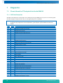
7.1.1 POST Code Checkpoints
The POST code checkpoints are the largest set of checkpoints during the BIOS pre-boot process. The following table
describes the type of checkpoints that may occur during the POST portion of the BIOS
Note:
Code
02h
03h
04h
06h
07h
08h
09h
0Ah
0Bh
0Ch
0Eh
0Fh
10h
11h
12h
13h
14h
16h
17h
18h
1Ah
1Ch
20h
22h
24h
28h
29h
2Ah
2Ch
2Eh
2Fh
32h
33h
36h
38h
3Ah
3Ch
3Dh
41h
42h
45h
46h
47h
48h
49h
4Ah
29
Checkpoints may differ between different platforms based on system configuration.
Checkpoints may change due to vendor requirements, system chipset or optional ROMs from add-in PCI
devices.
Beeps
1-2-2-3
1-3-1-1
1-3-1-3
1-3-4-1
1-3-4-3
2-1-2-3
POST Routine Description
Verify Real Mode
Disable Non-Maskable Interrupt (NMI)
Get CPU type
Initialize system hardware
Disable shadow and execute code from the ROM.
Initialize chipset with initial POST values
Set IN POST flag
Initialize CPU registers
Enable CPU cache
Initialize caches to initial POST values
Initialize I/O component
Initialize the local bus IDE
Initialize Power Management
Load alternate registers with initial POST valuesnew
Restore CPU control word during warm boot
Initialize PCI Bus Mastering devices
Initialize keyboard controller
BIOS ROM checksum
Initialize cache before memory Autosize
8254 timer initialization
8237 DMA controller initialization
Reset Programmable Interrupt Controller
Test DRAM refresh
Test 8742 Keyboard Controller
Set ES segment register to 4GB
Autosize DRAM
Initialize POST Memory Manager
Clear 512kB base RAM
RAM failure on address line xxxx*
RAM failure on data bits xxxx* of low byte of memory bus
Enable cache before system BIOS shadow
Test CPU bus-clock frequency
Initialize Phoenix Dispatch Manager
Warm start shut down
Shadow system BIOS ROM
Autosize cache
Advanced configuration of chipset registers
Load alternate registers with CMOS valuesnew
Initialize extended memory for ROM Pilot
Initialize interrupt vectors
POST device initialization
Check ROM copyright notice
Initialize I20 support
Check video configuration against CMOS
Initialize PCI bus and devices
Initialize all video adapters in system
www.kontron.com
smartCore Express SMA200 BIOS / Diagnostics
Code
4Bh
4Ch
4Eh
4Fh
50h
51h
52h
54h
55h
58h
59h
5Ah
5Bh
5Ch
60h
62h
64h
66h
67h
68h
69h
6Ah
6Bh
6Ch
6Eh
70h
72h
76h
7Ch
7Dh
7Eh
80h
81h
82h
83h
84h
85h
86h
87h
88h
89h
8Ah
8Bh
8Ch
8Fh
90h
91h
92h
93h
95h
96h
97h
98h
99h
9Ah
9Ch
9Dh
9Eh
9Fh
A0h
A2h
A4h
A8h
AAh
30
Beeps
2-2-3-1
1-2
POST Routine Description
QuietBoot start (optional)
Shadow video BIOS ROM
Display BIOS copyright notice
Initialize MultiBoot
Display CPU type and speed
Initialize EISA board
Test keyboard
Set key click if enabled
Enable USB devices
Test for unexpected interrupts
Initialize POST display service
Display prompt "Press F2 to enter SETUP"
Disable CPU cache
Test RAM between 512 and 640kB
Test extended memory
Test extended memory address lines
Jump to UserPatch1
Configure advanced cache registers
Initialize Multi Processor APIC
Enable external and CPU caches
Setup System Management Mode (SMM) area
Display external L2 cache size
Load custom defaults (optional)
Display shadow-area message
Display possible high address for UMB recovery
Display error messages
Check for configuration errors
Check for keyboard errors
Set up hardware interrupt vectors
Initialize Intelligent System Monitoring
Initialize coprocessor if present
Disable onboard Super I/O ports and IRQs
Late POST device initialization
Detect and install external RS232 ports
Configure non-MCD IDE controllers
Detect and install external parallel ports
Initialize PC-compatible PnP ISA devices
Re-initialize onboard I/O ports
Configure Motherboard Configurable Devices (optional)
Initialize BIOS Data Area
Enable Non-Maskable Interrupts (NMIs)
Initialize Extended BIOS Data Area
Test and initialize PS/2 mouse
Initialize floppy controller
Determine number of ATA drives (optional)
Initialize hard disk controllers
Initialize local-bus hard disk controllers
Jump to UserPatch2
Build MPTABLE for multi-processor boards
Install CD ROM for boot
Clear huge ES segment register
Fix up Multi Processor table
Search for option ROMs. One long, two short beeps on checksum failure
Check for SMART Drive (optional)
Shadow option ROMs
Set up Power Management
Initialize security engine (optional)
Enable hardware interrupts
Determine number of ATA and SCSI drives
Set time of day
Check key lock
Initialize typematic rate
Erase F2 prompt
Scan for F2 key stroke
www.kontron.com
smartCore Express SMA200 BIOS / Diagnostics
Code
ACh
AEh
B0h
B1h
B2h
B4h
B5h
B6h
B7h
B9h
BAh
BBh
BCh
BDh
BEh
BFh
C0h
C1h
C2h
C3h
C4h
C5h
C6h
C7h
C8h
C9h
CAh
CBh
CCh
CDh
CEh
D2h
Beeps
1
POST Routine Description
Enter SETUP
Clear Boot flag
Check for errors
Inform RomPilot about the end of POST
POST done – prepare to boot operating system
One short beep before boot
Terminate QuietBoot (optional)
Check password (optional)
Initialize ACPI BIOS
Prepare Boot
Initialize SMBIOS
Initialize PnP Option ROMs
Clear parity checkers
Display MultiBoot menu
Clear screen (optional)
Check virus and backup reminders
Try to boot with INT 19
Initialize POST Error Manager (PEM)
Initialize error logging
Initialize error display function
Initialize system error handler
PnPnd dual CMOS (optional)
Initialize note dock (optional)
Initialize note dock late
Force check (optional)
Extended checksum (optional)
Redirect Int 15h to enable remote keyboard
Redirect Int 13h to Memory Technologies Devices such as ROM, RAM, PCMCIA, and serial disk
Redirect Int 10h to enable remote serial video
Remap I/O and memory for PCMCIA
Initialize digitizer and display message
Unknown interrupt
The following are for Boot Block in the Flash ROM:
Code
E0h
E1h
E2h
E3h
E4h
E5h
E6h
E7h
E8h
E9h
EAh
EBh
ECh
EDh
EEh
EFh
F0h
F1h
F2h
F3h
F4h
F5h
F6h
F7h
31
Beeps
POST Routine Description
Initialize the chipset
Initialize the bridge
Initialize the CPU
Initialize system timer
Initialize system I/O
Check force recovery boot
Checksum BIOS ROM
Go to BIOS
Set Huge Segment
Initialize Multi Processor
Initialize OEM special code
Initialize PIC and DMA
Initialize Memory type
Initialize Memory size
Shadow Boot Block
System memory test
Initialize interrupt vectors
Initialize Run Time Clock
Initialize video
Initialize System Management Manager
Output one beep
Boot to Mini DOS
Clear Huge Segment
Boot to Full DOS
www.kontron.com
smartCore Express SMA200 BIOS / BIOS
8
BIOS
8.1
BIOS History
Vers.
Date
Status
Edited by
Modifications
Development
BRM/VIV
Pre-release development of the BIOS
Released
"
"
BRM/VIV
BRM/VIV
BRM/VIV
BIOS released
Programming of Fintek
ALC882 audio codec definition
Floppy controller disabled/Memory detection fixed/Firmware version
visible in BIOS setup
Fix for Fintek LPC UART
USB client fix
Fix of diagnostic screen & SuperIO address 200h
Fix of pcirst & audio for MID platform/New PCIe bus enumeration
IRQExclude menu added for LPC/ISA IRQ reservation
New microcode from Intel Rev. 217h
ACPI fix for PNP OS (PCI routing)
BIOS for MPCX28 can be used as standard/Tests for FPGA presence
Wake-up from PS2 KB/MS from S3 state
Fix of COM1&2 swap with COM3&4/PCIe fix
New Poulsbo firmware
C6 split VTT disabled
ASPM default set to disabled/sbinit.asm updated/Save-Restore FPGA &
F81216 content for S3 stated added
GPI07 output changed to fixed "1" disabling C6 control/Bootblock
Splash screen changed (Kontron was not black)
Switched to 1.5V DDR2 voltage in Poulsbo firmware
Fix in ACPI-COM ports from Fintek detection.
DMI info updated to Kontron/Serial port of IRQ of COM5 (Fintek)
corrected to IRQ5
Implemented Kontron DMI info
New SATA boot ext. V7.7.0.2/Fix for USB KB on USB controller 1
SATA boot ext. V7.4.0.5 for Windows XP compatibility
FPGA index changed to 0 at end of FPGA watchdog initialization/Content
of WD added (for save-restore from S3 state)
Universal version for SMA200 and MPCX28
Azalia codec table for Realtek added
1.00
1.01
1.02
17.06.2008
01.03.2009
12.03.2009
14.04.2009
17.04.2009
1.03
28.05.2009
Released
BRM/VIV
1.04
1.05
1.06
1.07
1.08
1.09
1.10
1.11
1.12
1.13
1.14
1.15_GTL
02.06.2009
01.07.2009
21.07.2009
13.08.2009
24.08.2009
27.08.2009
28.08.2009
31.08.2009
14.09.2009
03.11.2009
12.11.2009
03.12.2009
"
"
Released
"
"
Released
"
"
Released
"
"
Released
BRM
BRM
BRM
BRM/VIV
BRM
BRM
BRM
VIV
VIV
BRM
BRM
BRM
1.16_GTL
06.01.2010
"
BRM/VIV
1.17_GTL
1.18_GTL
1.19_GTL
1.20_GTL
07.01.2010
13.01.2010
08.02.2010
11.03.2010
"
Released
"
"
VIV
BRM
BRM
VIV
1.21_GTL
16.03.2010
Released
BRM
1.22_GTL
1.23_GTL
1.24_GTL
20.04.2010
29.04.2010
03.05.2010
23.09.2010
"
"
Released
VIV
BRM
BRM
"
VIV
"
BRM
0.010.18
1.25_GTL
1.26_GTL
32
05.10.2010
08.10.2010
www.kontron.com
smartCore Express SMA200 BIOS / BIOS
8.2
Specifications of the BIOS
Embedded BIOS
Remarks
ACPI PM
ACPI Battery Support
Boot Devices
CMOS-Data
BIOS Setup Backup
V3.0 Power Management
Not enabled
PATA, SATA, USB-Devices, LAN
Battery backed SRAM and a copy in the EEPROM
Automatically written into the EEPROM after setup-screen exit
Generally possible, setup data are transferred from the EEPROM.
The system integrator is responsible for testing and validating the application software on a batteryless platform.
Without backup-battery, the time and date counter is not running while the computer system is
switched off!
Possible, must be ordered separately
Possible, must be ordered separately
Supports PCI V2.2 with up to 6 resources
Supports PCI V2.2
Trusted Platform Module, optionally connectable to the SMB-Bus
Shutdown or restart, depends on the implementation
No
Compatible mode (IRQ14/15) or Native mode (PCI device)
Yes, Advanced Programmable Interrupt Controller
No
Yes, Enhanced Intel SpeedStep Technology
No
Z530 only
Yes, integrated in the ACPI
Throttling processor function
Control of the fan for active cooling
Critical trip point (the OS must shut down the system asap)
Catastrophic temperature (hardware shutdown)
Supported are:
S1 (POS = Power On Suspend)
S3 (STR = Suspend to RAM)
S4 (Suspend to Disk) is not supported by the BIOS; alternatively, the Win2000 and Win XP
Operating Systems use S4-OS (Hibernate)
Battery-less Boot
Customized CMOS
Customized User Data
PCI Parallel
PCIexpress
TPM V1.2
Watchdog Support
RAID Support
IDE Mode
APIC-Support
AHCI
EIST
Intel 64
Intel VT
Thermal Management
Supported
ACPI Suspend Modes
Wakeup Events
Remarks
Power Button
GPI1#
GPI2#
WOL, LAN wake event
SMBALERT#
PCIexpress WAKE#
PME#
Wakes unconditionally from S1-S5
Only if configured as LID Switc
Only if configured as RESUME ON RING
LAN driver must be configured for WOL
Wakes up unconditionally from S1-S5
Wakes up unconditionally from S1-S5
Activates the wake-up capabilities of a PCI-circuit
When standby mode S1 is set, the wake-up with USB MS/KB works. This depends on the system
implementations.
USB Mouse/KB
33
www.kontron.com
smartCore Express SMA200 BIOS / BIOS
8.3
Core BIOS Functions
INTEL Chipset Support US15W
Remarks
US15W Support with all timings (DDRAM , ...)
Auto-detect PCI/internal video in the US15W.
Internal video BIOS only if no PCI available.
Password/Security
Remarks
Standard functions
TCP/IP number for FirstWare tools
(browser, download service)
Multi-boot Setup
Remarks
Boot from FD
Boot from HD
Boot from CD
Boot from USB FD
Boot from USB CD
Boot from LAN
INTEL 82574L
Serial Remote Console Function
Remarks
Enable/Disable/Auto-detect
Select COM1 or COM2
LPC-Setup (LPC-SuperIO W83627HF)
Remarks
COM1
COM2
FD (and IRQ6)
LPT (and IRQ7)
PS/2-Keyboard (and IRQ1)
PS/2-MS (and IRQ12)
IRQ definitions
IRQ selection
IRQ selection
Enable/disable
Enable/disable
Enable/disable
Enable/disable
PnP, PCI, ISA
Keyboard Settings
Remarks
Standard-like
Typematic rate, numlock status, …
Power Management
Remarks
ACPI Functions
APM Function
AC-Full speed CPU Frequency select
Battery-Speed CPU Frequency select
Trottle temperature
Trottle function
Other thermal protection features of the
PENTIUM-M
Wake on LAN
Suspend to RAM (S3)
Suspend to Disk (S4)
Communication over SMB with the
PIC-PM-Controller for Wake-up/Suspend
AC-Detect for full speed
34
Enable/disable, setting of the TCP/IP number
Planned
No AC means battery-mode speed
www.kontron.com
smartCore Express SMA200 BIOS / BIOS
Wake Events
Remarks
LAN activity
KB activity
MS activity
Active ring signal
PWRBTN#
AVR Microcontroller
Suspend Events
Remarks
PWRBTN# (S2R or S2D)
No activity over a defined time
Software controlled shutdown
Smart Battery down
Time-controlled suspend
AVR Microcontroller
Select time from 1-255 minutes
Fast Boot
Remarks
Normal
Fast boot
Failure activity
Boot counter
15-25sec = normal boot
10-15sec = quick boot
No-Wait, Wait and error display, No-Wait and counter in the EEPROM
Enable/disable (in the EEPROM)
Screen
Remarks
Boot-up screen
Start-up resolution in the BIOS
Boot-up logo
CRT (SDVO) ,LVDS
640x480, 600x800, 1024x768
Enable/disable
For Realtime Operating Systems
Remarks
HotPlug-Service
USB-HotPlug Service
Enable/disable
Enable/disable
Battery-less BIOS-Setup
Remarks
Automatic save/reload of the EEPROM values
INT15 services
If battery fails
Download Functions
Remarks
CoreBIOS download
DOS / Windows
Watchdog (planned)
Remarks
Watchdog
Time out
Enable/disable
1, 10, 20, 30, 40, 50, 60 sec, 2, 3, 4, 5-32min
35
0%, 5%, 10%, 15%, 20%, off (SMB-detect of LTC1779)
www.kontron.com
smartCore Express SMA200 BIOS / BIOS
8.4
Core BIOS Download
Before downloading a BIOS, please check the following:
Make a bootable diskette which includes the following files:
» DELEP200.exe
» Phlash16.exe
» core BIOS (SM200_xxx_FLASHABL.ROM)
Rename the SM200_xxx_FLASHABL.ROM file to bios.rom
IMPORTANT:
Do not use boot disks created in a Windows operating system. If you do not have an MSDOS 6.22 disk
available, you can download a boot disk from www.bootdisk.com.
Notes:
Disable the EMM386 or other memory managers in the CONFIG.SYS of your bootdisk.
Make sure that the PHLASH16.exe program and the BIOS to be downloaded are in the same path and
directory!
Boot DOS without config.sys and autoexec.batpress F5 while starting the DOS boot.
Is the empty disk space, where the PHLASH16.exe is located, larger than 64kB (for safe storage)?
Is the floppy disk not write-protected?
Start the DOWNLOADING process:
1.
Start the system with the bootable diskette. If you do not have a bootable diskette or floppy drive you can
start in DOS mode by pressing the F5 key to disable the autoexec.bat and config.sys.
2.
Run DELEP200.exe to clear the CMOS and the EEPROM.
Warning
36
If you do not run DELEP200.exe, the system will be destroyed during the BIOS upgrade!
3.
Run PHLASH16.EXE BIOS.ROM /BBL
4.
If the BIOS download is finished, you must power off the system.
5.
After powering the system back on, press F2 to enter the setup mode and set the default values with F9.
6.
"Save and leave" the setup with F10.
7.
Power off the system.
8.
The download procedure is finished.
www.kontron.com
smartCore Express SMA200 BIOS / BIOS
8.5
BIOS Setup
Setup Menu Screens and Navigation
Keystroke Controls:
Function
Key
Enter Setup
Pop-up Boot Menu
F2
ESC
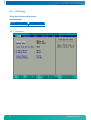
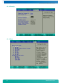
8.5.1 Main Menu
37
www.kontron.com
smartCore Express SMA200 BIOS / BIOS
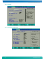
8.5.2 Advanced
8.5.3 Advanced I/O Configuration
38
www.kontron.com
smartCore Express SMA200 BIOS / BIOS
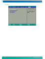
8.5.4 Advanced Console Redirection
8.5.5 Intel
39
www.kontron.com
smartCore Express SMA200 BIOS / BIOS
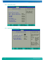
8.5.6 Intel CPU Control
8.5.7 Intel CPU Thermal Control
40
www.kontron.com
smartCore Express SMA200 BIOS / BIOS
8.5.8 Intel Poulsbo Control
8.5.9 Intel Poulsbo PCI Express Control
41
www.kontron.com
smartCore Express SMA200 BIOS / BIOS
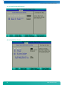
8.5.10 Intel Poulsbo USB Control
8.5.11 Intel Video Control
42
www.kontron.com
smartCore Express SMA200 BIOS / BIOS
8.5.12 Security
8.5.13 Boot
43
www.kontron.com
smartCore Express SMA200 BIOS / BIOS
8.5.14 Exit
44
www.kontron.com
smartCore Express SMA200 BIOS / BIOS
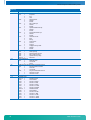
8.6
CMOS RAM Map
Systems based on the industry-standard specification include a battery backed real-time clock (RTC) chip. This clock
contains at least 64 Bytes of non-volatile RAM. The system BIOS uses this area to store information including system
configuration and initialization parameters, system diagnostics, and the time and date. This information remains
intact even when the system is powered down.
The BIOS supports 128 Bytes of CMOS RAM. This information is accessible through I/O ports 70h and 71h. CMOS RAM
can be divided into several segments:
» Locations 00h-0Fh contain the RTC and status information
» Locations 10h-2Fh contain system configuration data
» Locations 30h-3Fh contain system BIOS-specific configuration data as well as chipset-specific information
» Locations 40h-7Fh contain chipset-specific information as well as power management configuration
parameters
The following table provides a summary of how these areas may be further divided.
Beginning
Ending
Checksum
Description
00h
10h
2Eh
30h
34h
40h
5Ch
5Eh
6Fh
7Eh
0Fh
2Dh
2Fh
33h
3Fh
5Bh
5Dh
6Eh
7Dh
7Fh
No
Yes
No
No
No
Yes
No
No
Yes
No
RTC and Checksum
System Configuration
Checksum Value of 10h-2Dh
Standard CMOS
Standard CMOS - SystemSoft Reserved
Extended CMOS - Chipset Specific
Checksum Value of 40h-5Bh
Extended CMOS - Chipset Specific
Extended CMOS - Power Management
Checksum Value of 6Fh-7Dh
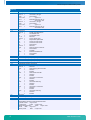
CMOS Map
Location
00h
01h
02h
03h
04h
05h
06h
07h
08h
09h
0Ah
45
Description
Time of day (seconds) specified in BCD
Alarm (seconds) specified in BCD
Time of day (minutes) specified in BCD
Alarm (minutes) specified in BCD
Time of day (hours) specified in BCD
Alarm (hours) specified in BCD
Day of week specified in BCD
Day of month specified in BCD
Month specified in BCD
Year specified in BCD
Status Register A
Bit 7
=
Update in progress
Bits 6-4 =
Time based frequency divider
Bits 3-0 =
Rate selection bits that define the periodic interrupt rate and output frequency.
www.kontron.com
smartCore Express SMA200 BIOS / BIOS
CMOS Map
Location
0Bh
0Ch
0Dh
0Eh
0Fh
10h
11h
46
Description
Status Register B
Bit 7
=
Run/Halt
0
Run
1
Halt
Bit 6
=
Periodic Timer
0
Disable
1
Enable
Bit 5
=
Alarm Interrupt
0
Disable
1
Enable
Bit 4
=
Update Ended Interrupt
0
Disable
1
Enable
Bit 3
=
Square Wave Interrupt
0
Disable
1
Enable
Bit 2
=
Calendar Format
0
BCD
1
Binary
Bit 1
=
Time Format
0
12-Hour
1
24-Hour
Bit 0
=
Daylight Savings Time
0
Disable
1
Enable
Status Register C
Bit 7
=
Interrupt Flag
Bit 6
=
Periodic Interrupt Flag
Bit 5
=
Alarm Interrupt Flag
Bit 4
=
Update Interrupt Flag
Bits 3-0 =
Reserved
Status Register D
Bit 7
=
Realtime Clock
0
Lost Power
1
Power
CMOS Location for Bad CMOS and Checksum Flags
Bit 7
=
Flag for CMOS Lost Power
0
=
Power OK
1
=
Lost Power
Bit 6
=
Flag for CMOS checksum bad
0
=
Checksum is valid
1
=
Checksum is bad
Shutdown Code
Diskette Drives
Bits 7-4 =
Diskette Drive A
0000
=
Not installed
0001
=
Drive A = 360 kB
0010
=
Drive A = 1.2MB
0011
=
Drive A = 720 kB
0100
=
Drive A = 1.44MB
0101
=
Drive A = 2.88MB
Bits 3-0 =
Diskette Drive B
0000
=
Not installed
0001
=
Drive B = 360 kB
0010
=
Drive B = 1.2MB
0011
=
Drive B = 720 kB
0100
=
Drive B = 1.44MB
0101
=
Drive B = 2.88MB
Reserved
www.kontron.com
smartCore Express SMA200 BIOS / BIOS
CMOS Map
Location
12h
Description
Fixed (Hard) Drives
Bits 7-4 =
0000
=
0001-1110
1111
=
Bits 3-0 =
0000
=
0001-1110
1111
=
13h
14h
15h
16h
17h
18h
19h
1Ah
1Bh
1Ch
1Dh
1Eh
1Fh - 24h
47
Hard Drive 0, AT Type
Not installed
=
Types 1-14
Extended drive types 16-44.
See location 19h.
Hard Drive 1, AT Type
Not installed
=
Types 1-14
Extended drive types 16-44.
See location 2Ah.
Reserved
Equipment
Bits 7-6 =
Number of Diskette Drives
00
=
One diskette drive
01
=
Two diskette drives
10, 11 =
Reserved
Bits 5-4 =
Primary Display Type
00
=
Adapter with option ROM
01
=
CGA in 40 column mode
10
=
CGA in 80 column mode
11
=
Monochrome
Bits 3-2 =
Reserved
Bit 1
=
Math Coprocessor Presence
0
=
Not installed
1
=
Installed
Bit 0
=
Bootable Diskette Drive
0
=
Not installed
1
=
Installed
Base Memory Size (in kB) - Low Byte
Base Memory Size (in kB) - High Byte
Extended Memory Size (in kB) - Low Byte
Extended Memory Size (in kB) - High Byte
Extended Drive Type - Hard Drive 0
Extended Drive Type - Hard Drive 1
Custom and Fixed (Hard) Drive Flags
Bits 7-6 =
Reserved
Bit 5
=
Internal Floppy Disk Controller
0
=
Disabled
1
=
Enabled
Bit 4
=
Internal IDE Controller
0
=
Disabled
1
=
Enabled
Bit 3
=
Hard Drive 0 Custom Flag
0
=
Disabled
1
=
Enabled
Bit 2
=
Hard Drive 0 IDE Flag
0
=
Disabled
1
=
Enabled
Bit 1
=
Hard Drive 1 Custom Flag
0
=
Disabled
1
=
Enabled
Bit 0
=
Hard Drive 1 IDE Flag
0
=
Disabled
1
=
Enabled
Reserved
EMS Memory Size Low Byte
EMS Memory Size High Byte
Custom Drive Table 0
These 6 Bytes (48 bits) contain the following data:
Cylinders 10bits range 0-1023
Landing Zone
10bits range 0-1023
Write Precompensation
10bits range 0-1023
Heads
8bits
range 0-15
Sectors/Track
8bits
range 0-254
www.kontron.com
smartCore Express SMA200 BIOS / BIOS
CMOS Map
Location
1Fh
20h
21h
22h
23h
24h
25h - 2Ah
25h
26h
27h
28h
29h
2Ah
2Bh
2Ch
2Dh
2Eh
2Fh
30h
31h
32h
33h
34h
35h
48
Description
Byte 0
Bits 7-0 =
Lower 8 bits of Cylinders
Byte 1
Bits 7-2 =
Lower 6 bits of Landing Zone
Bits 1-0 =
Upper 2 bits of Cylinders
Byte 2
Bits 7-4 =
Lower 4 bits of Write Precompensation
Bits 3-0 =
Upper 4 bits of Landing Zone
Byte 3
Bits 7-6 =
Reserved
Bits 5-0 =
Upper 6 bits of Write Precompensation
Byte 4
Bits 7-0 =
Number of Heads
Byte 5
Bits 7-0 =
Sectors Per Track
Custom Drive Table 1
These 6 Bytes (48 bits) contain the following data:
Cylinders 10bits range 0-1023
Landing Zone
10bits range 0-1023
Write Precompensation
10bits range 0-1023
Heads
8bits
range 0-15
Sectors/Track
8bits
range 0-254
Byte 0
Bits 7-0 =
Lower 8 bits of Cylinders
Byte 1
Bits 7-2 =
Lower 6 bits of Landing Zone
Bits 1-0 =
Upper 2 bits of Cylinders
Byte 2
Bits 7-4 =
Lower 4 bits of Write Precompensation
Bits 3-0 =
Upper 4 bits of Landing Zone
Byte 3
Bits 7-6 =
Reserved
Bits 5-0 =
Upper 6 bits of Write Precompensation
Byte 4
Bits 7-0 =
Number of Heads
Byte 5
Bits 7-0 =
Sectors Per Track
Boot Password
Bit 7
=
Enable/Disable Password
0
=
Disable Password
1
=
Enable Password
Bits 6-0 =
Calculated Password
SCU Password
Bit 7
=
Enable/Disable Password
0
=
Disable Password
1
=
Enable Password
Bits 6-0 =
Calculated Password
Reserved
High Byte of Checksum - Locations 10h to 2Dh
Low Byte of Checksum - Locations 10h to 2Dh
Extended RAM (kB) detected by POST - Low Byte
Extended RAM (kB) detected by POST - High Byte
BCD Value for Century
Base Memory Installed
Bit 7
=
Flag for Memory Size
0
=
640kB
1
=
512kB
Bits 6-0 =
Reserved
Minor CPU Revision
Differentiates CPUs within a CPU type (i.e., 486SX vs 486 DX, vs 486 DX/2). This is crucial for correctly
determining CPU input clock frequency. During a power-on reset, Reg DL holds minor CPU revision.
Major CPU Revision
Differentiates between different CPUs (i.e., 386, 486, Pentium). This is crucial for correctly determining CPU input
clock frequency. During a power-on reset, Reg DH holds major CPU revision.
www.kontron.com
smartCore Express SMA200 BIOS / BIOS
CMOS Map
Location
36h
40h-7Fh
49
Description
Hotkey Usage
Bits 7-6 =
Reserved
Bit 5
=
Semaphore for Completed POST
Bit 4
=
Semaphore for 0 Volt POST (not currently used)
Bit 3
=
Semaphore for already in SCU menu
Bit 2
=
Semaphore for already in PM menu
Bit 1
=
Semaphore for SCU menu call pending
Bit 0
=
Semaphore for PM menu call pending
Definitions for these locations vary depending on the chipset.
www.kontron.com
smartCore Express SMA200 BIOS / Appendix A: Document Revision History
9
Appendix A: Document Revision History
Revision
Date
Edited by
Changes
100
04.Jan.2010
WAS
Initial version from BRM 03.2009
101
19.Oct.2010
WAS
BIOS History updated. User-defined paper formatting corrected to A4 in Manual
Template
102
02.Feb.2011
WAS
Preface corrected. BSP screen shot & web links changed to KCC AG.
50
www.kontron.com
smartCore Express SMA200 BIOS / Index
10 Index
A
Environmental Protection................................... 5
Exit ..............................................................44
AC97 Sound ................................................... 19
I
B
I/O Config......................................................38
BIOS ............................................................ 32
Incompatibilities.............................................. 8
BIOS History .................................................. 32
Int15 Emulator Driver for Windows .................24, 28
BIOS Setup .................................................... 37
Int15 Hardware...............................................24
Boot............................................................. 43
Int15 Windows Software...............................25, 28
Intel Config....................................................39
C
Introduction.................................................... 8
CMOS RAM Map ............................................... 45
K
Console Redirection......................................... 39
Copyright ........................................................ 4
Keystroke Controls...........................................37
Core BIOS Download ........................................ 36
Core BIOS Functions ........................................ 34
Corporate Offices ............................................ 53
CPU Config..................................................... 40
CPU Thermal Config ......................................... 40
D
Diagnostics.................................................... 29
Display Driver................................................. 17
Document Revision History ............................... 50
Documentation................................................. 4
Driver Installation........................................... 11
L
Linux ............................................................10
M
Microsoft Windows............................................ 9
Microsoft Windows CE ........................................ 9
Microsoft Windows XPe ...................................... 9
O
Operating Systems Compatibility.......................... 9
AC97-Sound ......................................................... 14
Chipset ............................................................... 12
P
LAN .................................................................... 13
RAID................................................................... 14
PCI Express Config ...........................................41
VGA .................................................................... 12
Phoenix SecureCore™ Check Point Lists ................29
W2k/XP ............................................................... 25
Windows 2000 & XP ............................................... 11
Windows-NT ......................................................... 26
POST Code Checkpoints .....................................29
Poulsbo Config................................................41
Power Management..........................................21
E
Programming Int15dl .......................................26
ELinOS.......................................................... 10
51
www.kontron.com
smartCore Express SMA200 BIOS / Index
Q
Swiss Association for Quality and Management
Systems....................................................... 7
QNX ............................................................. 10
Swiss Quality ................................................... 6
R
T
Real-time OS .................................................. 10
Technical Support............................................. 5
RoHS.............................................................. 5
Trademarks ..................................................... 4
S
U
Security ........................................................ 43
USB Config.....................................................42
SFI............................................................... 22
SLAX ............................................................ 10
V
Special Function Interface ................................ 22
Specification
BIOS................................................................... 33
Video Config ...................................................42
VxWorks ........................................................10
SpeedStep ..................................................... 20
SQS................................................................ 7
Standard Features ............................................. 8
Standards........................................................ 4
52
W
Warranty ........................................................ 4
WEEE ............................................................. 6
www.kontron.com
smartCore Express SMA200 BIOS / Index
Corporate Offices
Europe, Middle East & Africa
Switzerland
Kontron AG
Oskar-von-Miller-Strasse 1
85386 Eching/Munich
Germany
Tel.: +49 (0)8165/ 77 777
Fax: +49 (0)8165/ 77 219
Kontron Compact Computers AG
Nordstrasse 11/F
CH – 4542 Luterbach
Switzerland
Tel.: +41 (0)32 681 58 00
Fax: +41 (0)32 681 58 01
[email protected]
[email protected]
53
www.kontron.com