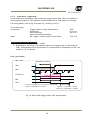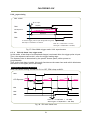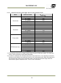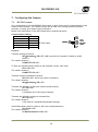
1
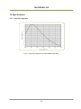
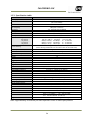
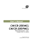
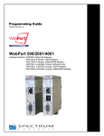
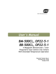
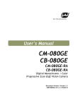
User's Manual CM-030PMCL-RH 1/3” Progressive Scan Monochrome Remote Head Camera Document Version: 1.1 CM-030PMCL-RH_Ver.1.1_Sept09 CM-030PMCL-RH Notice The material contained in this manual consists of information that is proprietary to JAI Ltd., Japan and may only be used by the purchasers of the product. JAI Ltd., Japan makes no warranty for the use of its product and assumes no responsibility for any errors which may appear or for damages resulting from the use of the information contained herein. JAI Ltd., Japan reserves the right to make changes without notice. Company and product names mentioned in this manual are trademarks or registered trademarks of their respective owners. Warranty For information about the warranty, please contact your factory representative. Certifications CE compliance As defined by the Directive 2004/108/EC of the European Parliament and of the Council, EMC (Electromagnetic compatibility), JAI Ltd., Japan declares that CM-030PMCL-RH complies with the following provisions applying to its standards. EN 61000-6-3 (Generic emission standard part 1) EN 61000-6-2 (Generic immunity standard part 1) FCC This equipment has been tested and found to comply with the limits for a Class B digital device, pursuant to Part 15 of the FCC Rules. These limits are designed to provide reasonable protection against harmful interference in a residential installation. This equipment generates, uses and can radiate radio frequency energy and, if not installed and used in accordance with the instructions, may cause harmful interference to radio communications. However, there is no guarantee that interference will not occur in a particular installation. If this equipment does cause harmful interference to radio or television reception, which can be determined by turning the equipment off and on, the user is encouraged to try to correct the interference by one or more of the following measures: - Reorient or relocate the receiving antenna. - Increase the separation between the equipment and receiver. - Connect the equipment into an outlet on a circuit different from that to which the receiver is connected. - Consult the dealer or an experienced radio/TV technician for help. Warning Changes or modifications to this unit not expressly approved by the party responsible for FCC compliance could void the user’s authority to operate the equipment. 2 CM-030PMCL-RH CM-030PMCL-RH - Contents 1. 2. 3. 4. 5. General .............................................................................................. 5 Camera nomenclature ............................................................................. 5 Main Features ....................................................................................... 5 Locations and Functions ........................................................................... 6 Pin Assignment ...................................................................................... 7 5.1. Digital Output Connector for Mini-CL (Camera Link) .......................................... 7 5.2. Camera Link interface.............................................................................. 7 6. Functions and Operations ......................................................................... 9 6.1. Basic functions ...................................................................................... 9 6.1.1. Digital Video Output (Bit Allocation) ..................................................... 9 6.1.2. Electronic Shutter .......................................................................... 10 6.1.3. Continuous operation or triggered operation .......................................... 11 6.1.4. Rear panel indicator ....................................................................... 11 6.1.5. Auto-detect LVAL-sync / async. accumulation ........................................ 11 6.1.6. Vertical Binning ............................................................................. 12 6.2. Sensor Layout and timing ......................................................................... 13 6.2.1. CCD Sensor Layout ......................................................................... 13 6.2.2. Horizontal timing ........................................................................... 14 6.2.3. Vertical timing .............................................................................. 14 6.2.4. Partial Scan.................................................................................. 15 6.2.5. Vertical Binning ............................................................................. 16 6.3. Operation Modes ................................................................................... 17 6.3.1. Continuous operation ...................................................................... 17 6.3.2. Pre-select Trigger Mode ................................................................... 18 6.3.3. Pulse Width Trigger Mode ................................................................ 20 6.3.4. EPS with Smear Less trigger mode ....................................................... 21 6.3.5. Minimum interval of the trigger input on each operation mode .................... 22 6.4. Mode and function matrix. ....................................................................... 23 7. Configuring the Camera ..........................................................................24 7.1. RS-232C control .................................................................................... 24 7.2. Setting functions ................................................................................... 25 7.2.1. Bit allocation. BA=0, BA=1 ............................................................... 25 7.2.2. Partial scan. SC=0 through 4. ............................................................. 25 7.2.3. Vertical binning. VB=0, VB=1 ............................................................ 25 7.2.4. Shutter mode. SM=0 and SM=1 ........................................................... 25 7.2.5. Trigger polarity. TP=0, TP=1. ............................................................ 25 7.2.6. Gain level. GA=-84 through +336. ....................................................... 25 7.2.7. Black level. BL=0 through BL=1023. ..................................................... 25 7.3. Save and Load Functions .......................................................................... 25 7.4. CM-030PMCL-RH command list ................................................................... 26 8. Camera Control Tool for CM-030PMCL-RH .....................................................28 8.1. Camera Control Tool Interface .................................................................. 28 8.1.1. Camera Control Tool Bar .................................................................. 28 8.2. The About Window ................................................................................. 28 8.3. Communication Window .......................................................................... 29 8.4. Camera Control Window .......................................................................... 30 8.5. Using the Camera Control Tool .................................................................. 30 9. External Appearance and Dimensions ..........................................................32 10. Specifications ......................................................................................33 10.1. Spectral response .................................................................................. 33 10.2. Specification table ................................................................................. 34 11. Appendix ...............................................................................................35 3 CM-030PMCL-RH 11.1. Precautions ............................................................................................ 35 11.2. Typical Sensor Characteristics ...................................................................... 35 11.3. Caution when mounting a lens on the camera ................................................. 35 11.4. Caution when mounting the camera .............................................................. 36 11.5. Exportation........................................................................................... 36 11.6. References ............................................................................................. 36 Change History .............................................................................................38 User's Record ...............................................................................................39 4 CM-030PMCL-RH 1. General CM-030PMCL-RH is 17mm diameter Remote Head camera using 330L pixels, monochrome progressive scan CCD. This camera achieves a high speed frame rate of 120.491frames per second. The camera head is small, so it suitable for such machine vision applications as surface mounting, semiconductor inspection, surface inspection etc. CM-030PMCL employs PoCL (Power on Camera Link) function and the camera operates full functions by just connecting the cable with a POCL compatible frame grabber. CM-030PMCL-RH is equipped with partial scan and vertical binning modes. Using these functions the camera achieves higher frame rates. The latest version of this manual can be downloaded from: www.jai.com The latest version of Camera Control Tool for CM-030PMCL-RH can be downloaded from: www.jai.com For camera revision history, please contact your local JAI distributor. 2. Camera nomenclature The standard camera composition consists of: Camera body x1 Sensor Protection cap x1 The camera is available in the following versions: CM-030PMCL-RH Where C stands for "Compact" family, M stands for "Monochrome", 30 represents the resolution "330K pixels", and PMCL for interface with “Power over Mini-CL” Options: OP735 OP715 OP724 PD-12U series Lens f=7.5mm, F=1.6 Lens f=15mm, F=2.0 Lens f=24mm, F=3.1 AC power adaptor 3. Main Features φ17mm Remote head system with 1/3 inch Progressive CCD High frame rate of 120 fps in Continuous mode, Full resolution 659 (h) x 494 (v) active pixels 7.4 µm square pixels 120 frames/second with external trigger and full resolution Up to 504 frames/second with partial scan of 1/8 193 frames/second with vertical binning Shutter speed from 32.48μs to 2 sec. using Pulse Width Control Programmable exposure from 32.48μs to 8.299 ms by 1 LVAL (16.24µs) increments Pre-select, Pulse width and Pre-select with Smear Less trigger modes LVAL-synchronous/-asynchronous operation (auto-detect) PoCL (Power over CL) standard compliant 10 or 8-bit output Setup by Windows NT/2000/XP via serial communication 5 CM-030PMCL-RH 4. Locations and Functions Serial No. Z ⑤ ② ③ ④ FCCseal ① ⑧ POWER TRIG / PoCL ⑨ ⑥ CCD sensor Lens mount Lock ring Camera head Camera cable 12-pin connector 12-pin receptacle 26-pin connector LED Mounting holes Serial No. Cautionseal ⑦ 1/2 inch CCD sensor Excluding mount M15.5 x 0.5 Is used to fix the focus position φ17mm Camera Head 2m Connecting with CCU Connecting with Camera Head POCL, Camera Link Interface (Mini-CL) (Note *1) Indication for power and trigger input M3 depth 3.5mm for tripod mount plate *1) Note: When a Camera Link cable is connected to the camera, please do not excessively tighten screws by using a screw driver. The Camera Link receptacle on the camera might get damaged. For security, the force to tighten screws should be less than 0.291 Newton meter (Nm). Tightening by hand is sufficient in order to achieve this. The camera link cable must comply with PoCL standard. Fig. 1. Locations ( version) 6 CM-030PMCL-RH 5. Pin Assignment 5.1. Digital Output Connector for Mini-CL (Camera Link) Type: 26-pin SDR connector (3M or Honda type) Mini-CL connector Fig.2. Mini-CL connector Pin No 1 13 14 26 7(+),20(-) 8(-),21(+) 10(+),23(-) 9(-),22(+) 6(-),19(+) 4(-),17(+) 3(-),16(+) 2(-),15(+) 5(-),18(+) I/O I I I I I/O O I I O O O O O Name DC +12V GND GND DC +12V RXD TXD Reserve Trigger TxOUT3 TxOUT2 TxOUT1 TxOUT0 TxClk Note For # 26 pin For # 1 pin Serial Com. CC1 Ext. Trigger in Camera Link out Clock for CL Important Note for PMCL version CM-030PMCL-RH camera feature “Safe Power” circuit which is specified by the PoCL standard. This circuit is used to verify the presence of camera and PoCL cable before the frame grabber provides power. 5.2. Camera Link interface The digital video is available via Camera Link, with 8 or 10-bit pixel depth, using the CL Base configuration. The digital output signals follow the Camera Link standard using Channel Link chip sets. The data bits from the digital video, FVAL, LVAL, DVAL and EEN are multiplexed into the twisted pairs, which are a part of the Camera Link. Trigger signals and the serial camera control are transmitted directly through its own pairs. The 26-pin Mini-CL SDR connector pin assignment follows the Camera Link base configuration. For a detailed description of the Camera Link standard, please refer to the Camera Link standard specifications found on www.jai.com. 7 CM-030PMCL-RH Port/Signal 8bitoutput 10bitoutput Port A0 L2 L0 Port A1 L3 L1 Port A2 L4 L2 Port A3 L5 L3 Port A4 L6 L4 Port A5 L7 L5 Port A6 L8 L6 Port A7 L9 L7 Port B0 NC L8 Port B1 NC L9 Port B2 NC NC Port B3 NC NC Port B4 NC NC Port B5 NC NC Port B6 NC NC Port B7 NC NC Port C0 NC NC Port C1 NC NC Port C2 NC NC Port C3 NC NC Port C4 NC NC Port C5 NC NC Port C6 NC NC Port C7 NC NC LVAL FVAL DVAL EEN Pin No. Tx0 Tx1 Tx2 Tx3 Tx4 Tx6 Tx27 Tx5 Tx7 Tx8 Tx9 Tx12 Tx13 Tx14 Tx10 Tx11 Tx15 Tx18 Tx19 Tx20 Tx21 Tx22 Tx16 Tx17 Tx24 Tx25 Tx26 Tx23 (Output Timing) 1 pixel cycle TxCLK TxOUT3 A7 A6 EEN C7 C6 B7 B6 A7 A6 TxOUT2 C3 C2 DVAL FVAL LVAL C5 C4 C3 C2 TxOUT1 B2 B1 C1 C0 B5 B4 B3 B2 B1 TxOUT0 A1 A0 B0 A5 A4 A3 A2 A1 A0 8 CM-030PMCL-RH 6. Functions and Operations 6.1. Basic functions The CM-030PMCL-RH camera is 17mm diameter small remote head camera using 330K pixels, monochrome progressive CCD. The length between a camera head and the CCU is 2m and the cable is attached on the camera head. The frame rate is as high as 120.491 fps. The interface to the host PC is via digital Mini Camera Link (Mini-CL) with POCL capability. The output video is either 8 or 10 bits. The camera has 2/3, 1/2, 1/4 or 1/8 partial scanning and vertical binning for faster frame rates. There are 3 trigger modes in addition to continuous operation. The Pre-Select, Pulse Width control and Pre-select with Smear Less are available with a unique automatic LVAL sync or async selection function. Below the functions are described in detail. 6.1.1. Digital Video Output (Bit Allocation) The 10-bit digital output is set 890 LSB as 100% video level when CCD output is 200mV. The white clip level is set at 1023 LSB when CCD output is 230mV. CCD out Black 200mV 230mV↑ Analogue level Setup 3.6%, 25mV 700mV 800mV Digital Out( 10 bits ) 32LSB 890LSB 1023LSB Fig.3. Digital Output Bit Allocation ( 10 Bits output ) 9 CM-030PMCL-RH 6.1.2. Electronic Shutter CM-0303PMCL-RH allows selecting shutter speed in two ways; preset shutter (10 fixed steps) and programmable exposure (in 511 line period, LVAL, increments). Preset Shutter The following shutter speeds can be selected by command SH=0 through SH=9. OFF (1/120), 1/250, 1/500, 1/1000, 1/2000, 1/4000, 1/8000, 1/10000, 1/15000, 1/30000 seconds Programmable Exposure (PE) The exposure time can be programmed in 16.24µs (LVAL period) increments. The range is from 2 LVAL to 511 LVAL. Minimum exposure time 2L 16.24 µs x 2(L) = 32.48 µs Maximum exposure time 511L 16.24 µs x 511 (L) ≈ 8.299 ms In binning mode: Minimum Exposure time 2L 20.069 µs x 2(L) = 40.138 µs Maximum exposure time 257L 20.069 µs x 257 (L) ≈ 5.158 ms Preset shutter time for each output mode The preset shutter value is converted to the programmable value (PE) inside the camera. Accordingly, there is a slight difference between the preset shutter value and the actual exposure time. Please refer the following table. Preset Shutter Value[s] Off(1/120) 1/250 1/500 1/1000 1/2000 1/4000 1/8000 1/10000 1/15000 1/30000 Exposure lines [Line] 511 246 123 62 31 15 8 6 4 2 Actual exposure FULL (µs) 8299 3995 1998 1007 503 244 130 97.4 65 32.5 VBinning(µs) 5158 4937 2468 1244 622 301 161 120 80.3 40.1 10 CM-030PMCL-RH 6.1.3. Continuous operation or triggered operation The camera can operate in continuous operation applications not requiring asynchronous external trigger. The camera will operate at its maximum frame rate, 120.491 frames/seconds in this mode. For applications that require an external trigger, the camera can accept an external trigger input via the Camera Link interface. The camera can operate with up to 120 frames/second in triggered operation as well. 6.1.4. Rear panel indicator The rear panel mounted LED provides the following information: POWER / TRIG Amber: Power connected - initiating Steady green: Camera is operating in Continuous mode Flashing green: The camera is receiving external trigger POCL Fig.4. Rear panel 6.1.5. Auto-detect LVAL-sync / async. accumulation This function replaces the manual setting found in older JAI cameras. Whether accumulation is synchronous or a-synchronous in relationship to LVAL depends on the timing of the trigger input. When trigger is received while FVAL is high (during readout), the camera works in LVAL synchronous mode, preventing reset feed trough in the video signal. There is a maximum jitter of one LVAL period from issuing a trigger and accumulation start. If trigger is received when FVAL is low, the cameras works in LVAL-asynchronous mode (no delay) mode. This applies to both pre-select (PS) trigger mode and pulse width trigger (PW) modes. Ext. trigger (1) (2) (3) FVAL (1) In this period camera executes trigger at next LVAL (prevents feed-through noise) (2) Avoid trigger at FVAL transition (+/- 1 LVAL period), as the function may randomly switch between "next LVAL" and "immediate". (3) In this period camera executes trigger immediately (no delay) Fig. 5. Auto-detect LVAL sync /a-sync accumulation 11 CM-030PMCL-RH 6.1.6. Vertical Binning Binning mode (Command VB) is a function where the signal charge from 2 adjacent (vertical) pixels are added together and read out as one pixel. Binning results in half vertical resolution and higher frame rate. By adding 2 pixels together, the sensitivity is doubled. The charge accumulated in 2 adjacent lines is added together in the horizontal CCD register. This is done by providing two pulses to the vertical CCD register for each line readout. Vertical binning cannot be used together with the Partial scan. Pixel H Xsg1 Vertical CCD Register Normal full scanning H 2 line Vertical Binning Video Out Reset Horizontal CCD Register S/H Fig. 6. Vertical Binning 12 CM-030PMCL-RH 6.2. Sensor Layout and timing 6.2.1. CCD Sensor Layout The CCD sensor layout with respect to pixels and lines used in the timing and video full frame read out is shown below. 692 7 2 Read Out ( Vertical) OB Effective Video Output 511 504 494 659 x 494 Pixel ( 1,1) Optical Black 88 942 clock 1 2 659 31 OB OB Read Out ( Horizontal) Fig. 7 CCD sensor layout 13 249 OB CM-030PMCL-RH 6.2.2. Horizontal timing The LVAL period is shown for continuous mode. FULL FRAME READ OUT / PARTIAL READ OUT 1LVAL 942ck =16.24us LVAL 1ck= 17.24ns 693ck DATA OUT 249ck Valid data 3ck 2ck 659ck OB 31ck 673ck 269ck DVAL Fig. 8 Horizontal timing 6.2.3. Vertical timing The FVAL period for continuous mode full scan is shown. Fig. 9. Vertical timing for full scan 14 CM-030PMCL-RH 6.2.4. Partial Scan Partial scan allows higher frame rate by reading out a smaller center portion of the image. This is particularly useful when inspecting objects that do not fill the whole height of the image. Fast-dump period Normal scan period Fast-dump period Full scan Partial scan Vertical Timing The below diagram and table provide vertical timing information for the fixed partial scan settings 1/2, 1/4, 1/3 and 2/3 PARTIAL FRAME READ OUT LVAL FVAL DVAL 3L DATA 1L Valid data CCD Exposure EEN A B C Values for vertical timing in partial scan continuous mode. AREA FVAL Low (L) A (L) 2/3 3 14 1/2 3 19 1/4 3 27 1/8 3 31 B (L) Start line End line 328 83 410 246 123 368 122 185 306 60 215 274 C (L) Total line (L) frame rate (L) 11 356 172.95 16 284 216.80 24 176 349.83 28 124 504.72 Fig. 10. Vertical timing for partial scanning 15 CM-030PMCL-RH Horizontal Timing The horizontal timing is the same the full scanning. FULL FRAME READ OUT / PARTIAL READ OUT 1LVAL 942ck =16.24us LVAL 1ck= 17.24ns 693ck DATA OUT 249ck Valid data 3ck 2ck 659ck OB 31ck 673ck 269ck DVAL Fig. 11. Horizontal timing for partial scanning 6.2.5. Vertical Binning Vertical binning combines charge from two adjacent lines, reducing the vertical resolution to half and at the same time increasing frame rate and sensitivity. By activating this function, the frame rate is increased to 193.9 fps. Important Note Vertical Binning cannot be used together with the Partial Scan mode. Horizontal Timing Fig.12. Horizontal Timing for Vertical Binning 16 CM-030PMCL-RH Vertical timing Fig.13. Vertical Timing for Vertical Binning 6.3. Operation Modes This camera can operate in 4 primary modes. 1. 2. 3. 4. TR=0 TR=1 TR=2 TR=3 Continuous Mode Pre-select Mode Pulse Width Mode EPS with Smear less Mode Pre-selected exposure. Pre-selected exposure. Pulse width controlled exposure. Pre-selected exposure. 6.3.1. Continuous operation For applications not requiring asynchronous external trigger, but should run in continuous operation, this mode is used. For timing details, refer to fig. 8 through fig. 13. To use this mode: Set function: Trigger mode to “Continuous”. Scanning V Binning Shutter mode pre-set or programmable Shutter speed SH=0 to 9 Programmable exp. Other functions and settings 17 TR=0 SC=0 through 4 VB=0 or 1 SM=0 or 1 PE=2 to 511 CM-030PMCL-RH 6.3.2. Pre-select Trigger Mode An external trigger pulse initiates the capture, and the exposure time (accumulation time) is defined by the SH or PE commands. The resulting video signal will start to be read out after the selected shutter time. For timing details, refer to fig. 8 through fig. 13 and fig. 14 & 15. To use this mode: Set function: Trigger mode to “Edge pre-select” Scanning V Binning Shutter mode to pre-set or programmable SM=0 or 1 Shutter speed SH=0 to 9 Programmable exp. Other functions and settings Ext. trigger. Camera Link or 12-pin Hirose Input: TR=1 SC=0 to 4 VB=0 or 1 PE=2 to 511 TI=0, TI=1 Important notes on using this mode 1. The minimum trigger interval >1 LVAL. 2. Depending on the timing of the leading edge of the trigger pulse in relationship to FVAL, accumulation will be synchronous or a-synchronous in relationship to LVAL. See chapter 6.1.5 for details. LVAL_sync timing LVAL SYNC TRIG 2L(min) LVAL 1L~2L CCD Expsoure EEN Exposure FVAL In case the trigger pulse is input during FVAL being HIGH, FULL:6L (97.44us) Vbinni ng:4L(80.28us) LVAL sync accumulation is initiated. Fig. 14. Pre-select trigger mode. LVAL synchronized. 18 CM-030PMCL-RH LVAL_async timing LVAL ASYNC 3μ s± 1μ s TRIG 2L(min) CCD Exposure EEN Exposure FVAL In case the trigger pulse is input during FVAL being LOW, FULL: 6L ~ 7.1L(97.44us~115.30us) LVAL async accumulation is initiated. Vbinnin g:4L~ 5.2L (80.28us~104.36us) Fig.15. Pre-select trigger mode. LVAL asynchronous 19 CM-030PMCL-RH 6.3.3. Pulse Width Trigger Mode In this mode the accumulation time is equal the trigger pulse width. Here it is possible to have long time exposure. The maximum recommended time is <240 frames ( 2 seconds). For timing details, refer to fig. 8 through fig. 13 and fig. 16 & 17. To use this mode: Set function: Input: Trigger mode to “Pulse width control”. Partial scan Vertical binning Other functions and settings Ext. trigger. Camera Link or 12-pin Hirose TR=2 SC=0 to 4 VB= 0 or 1 TI=0, TI=1 Important notes on using this mode 1. The minimum trigger interval > 1 LVAL 2. Depending on the timing of the leading edge of the trigger pulse in relationship to FVAL, accumulation will be synchronous or a-synchronous in relationship to LVAL. See chapter 6.1.5. for details. LVAL_sync timing LVAL SYNC TRIG Raising prohibited TRIG 2L(min) LVAL CCD Exposure 1L 1L( max) Exposure EEN FVAL In case the trigger pulse is input during FVAL being HIGH, LVAL sync accumulation is initiated. FULL: 6L ~ 7.1L(97.44us ~ 115.3us) Vbinnig:4L ~ 5.2L(80.28us ~ 104.36us) Fig. 16. Pulse width trigger mode. LVAL synchronized. 20 CM-030PMCL-RH LVAL_async timing LVAL ASYNC 3μ s± 1μ s 2L(min) TRIG 1L CCD Exposure EEN Exposure FVAL In case the trigger pulse is input during FVAL being LOW, LVAL async accumulation is initiated. FULL: 6L~ 7.1L(97.44us ~ 115.3us) Vbinnig:4L~ 5.2L(80.28us ~ 104.36us) Fig.17. Pulse Width trigger mode. LVAL asynchronous 6.3.4. EPS with Smear Less trigger mode In this mode, a fast dump of accumulated charges is activated after the trigger pulse is input. Then, the exposure starts at 64 L after the trigger leading edge. The exposure time is determined by the presser shutter speed, either presser or programmable. Thus, as the fast dump is made, this mode functions as the smear less mode which eliminates the smear on the upper part of the image. Important notes on using this mode When the shutter setting is either PE=511 or OFF, EEN is kept as HIGH. TRIG CCD Exposure 1.0231 ms (63L) EEN FVAL DVAL FULL: 6L ~7.1L(97.44us ~ 115.30us) Vbinni ng:4L ~5.2L(80.27us ~ 104.35us) Fig. 18. EPS with Smear Less 21 CM-030PMCL-RH 6.3.5. Minimum interval of the trigger input on each operation mode Mode Continuous Pre-select Pulse width EPS(Smear less) Read out mode Full 2/3 Partial 1/2 Partial 1/4 Partial 1/8 Partial V. Binning Full 2/3 Partial 1/2 Partial 1/4 Partial 1/8 Partial V. Binning Full 2/3 Partial 1/2 Partial 1/4 Partial 1/8 Partial V. Binning Full 2/3 Partial 1/2 Partial 1/4 Partial 1/8 Partial V. Binning Line(Trigger minimum interval)* 511 356 284 176 122 257 513 359 287 179 125 259 513 359 287 179 125 259 578 423 351 243 189 324 *1) The minimum interval for trigger modes shows in case of LVAL sync mode. For LVAL sync mode, the accumulation time should be added. *2) In order to maintain the minimum interval on the partial scan, it is necessary so that the exposure time should not exceed the lines for the continuous mode. When the exposure is set at longer than that of the continuous mode, the interval becomes longer than the described by figures (Exposure time – Lines of the continuous). 22 CM-030PMCL-RH 6.4. Mode and function matrix. The following table shows which functions will work in the different modes for CM-030PMCLRH. Shutter Func. Trigger Mode Partial scan Pre-select Programmable V Binning Accumulation LVAL sync/async Cont. TR=0 Yes Yes Yes Yes - EPS TR=1 Yes Yes Yes Yes Auto PWC TR=2 - - Yes Yes Auto EPS w/ Smearless TR=3 Yes Yes Yes Yes Async only Fig. 19. Mode and function matrix. 23 CM-030PMCL-RH 7. Configuring the Camera 7.1. RS-232C control Any configuration of the CM-030PMCL-RH camera is done via the serial communication in the Camera Link connector. The camera can be set up from a PC running terminal emulator software, or using JAI's camera control software. Below is the description of the ASCII based short command protocol. Communication setting Baud Rate Data Length Start Bit Stop Bit Parity Xon/Xoff Control 9600 bps 8 bit 1 bit 1 bit None None TXD CAMERA RXD GND RS 232C cable 1 CD 4 DTR 6 DSR 2 RXD 3 TXD 5 GND 7 RTS 8 CTS 9 CI 9 pin D-con PC COM PORT Protocol Transmit setting to camera: NN=Parameter<CR><LF> (NN is any kind of command. Capital or small letters.) The camera answers: COMPLETE<CR><LF> To have all communication visible on the emulator screen, start with: EB=1<CR><LF> The camera answers: COMPLETE<CR><LF> Transmit request command to camera: NN?<CR><LF> (NN is any kind of command.) The camera answers: NN=Parameter<CR><LF> Transmit the following to have the camera actual setting: ST?<CR><LF> The camera answers: A complete list of the current settings Transmit the following to have a command list: HP?<CR><LF> The camera answers: A list with all commands and possible settings Invalid parameters send to camera: (99 is an invalid parameter) SH=99<CR><LF> The camera answers: 02 Bad Parameters!!<CR><LF> 24 CM-030PMCL-RH To see firmware number: VN?<CR><LF> To see camera ID: The manufacturing lot number is shown. ID?<CR><LF> 7.2. Setting functions 7.2.1. Bit allocation. BA=0, BA=1 This command sets the output for either 8-bit or 10-bit. 7.2.2. Partial scan. SC=0 through 4. The CCD scanning format can be selected between full or partial scanning. With partial scanning only the vertical central part of the CCD sensor is read out with a higher frame rate. The partial scan is done by a fast dump read out of the lines in the vertical CCD register down to the top of the partial image. This central part of the image is read out with normal speed. The lines below the partial image are read out and dumped with a high speed. 7.2.3. Vertical binning. VB=0, VB=1 The CM-030PMCL-RH has only vertical binning mode. With V binning the pixel charge from 2 adjacent lines are added together in the horizontal CCD register. It is done by double pulses to the vertical CCD register. Note: Vertical Binning cannot be used together with the Partial scanning. 7.2.4. Shutter mode. SM=0 and SM=1 With SM=0 this function selects the shutter from the 10fixed steps (SH=0 through SH=9). With SM=1 from programmable in 550 steps (PE=2 through PE=551). 7.2.5. Trigger polarity. TP=0, TP=1. The active trigger polarity is low as default (TP=0). It can be invert it to active high (TP=1). 7.2.6. Gain level. GA=-84 through +336. GA=0 is 0dB gain, which is normal working point. The range is from -3 dB to +12 dB. 7.2.7. Black level. BL=0 through BL=1023. Black level (or set-up level) will set the video level for black. Factory setting is 32 LSB for 10bit or 8 LSB for 8bit. 7.3. Save and Load Functions The following commands are used to store and load camera settings in the camera EEPROM. Load settings. LD This command will load previous stored settings to the camera. 3 user settings can be stored in the camera EEPROM. 1 factory setting is also stored in the camera. The settings stored in the last used user area are used as default settings at power up. 25 CM-030PMCL-RH Save Settings. SA This command will store the actual camera settings to 1 of the 3 user area in the camera EEPROM. EEPROM Area. EA If received, the camera will return the last used user area number. 7.4. CM-030PMCL-RH command list Command Name Format Parameter Remarks A - General settings and utility commands. EB=[Param.]<CR><LF> EB?<CR><LF> 0=Echo off 1=Echo on 1 Echo Back 2 Camera Status Request ST?<CR><LF> Actual setting 3 Online Help Request HP?<CR><LF> Command list 4 Firmware Version VN?<CR><LF> 3 digits (e.g.) 100 = Version 1.00 5 Camera ID Request ID?<CR><LF> max 10 characters 6 Model Name Request MD?<CR><LF> max 11 characters UD=[Param.]<CR><LF> UD?<CR><LF> User can save and load free text.(11 or less characters) 7 User ID Off at power up B – Shutter 1 Shutter Mode SM=[Param.]<CR><LF> SM?<CR><LF> 0=Preset Shutter 1=Programmable exposure 0=Off, 1=1/250, 2=1/500, 3=1/1000, 4=1/2000, 5=1/4000, 6=1/8000, 7=1/10000, 8=1/15000, 9=1/30000 2 Preset Shutter SH=[Param.]<CR><LF> SH?<CR><LF> 3 Programmable Exposure PE=[Param.]<CR><LF> PE?<CR><LF> 2 to 511 C - Trigger mode 1 Trigger Mode 0=Normal (Continuous) 1=EPS(Edge pre select) 2=PWC(Pulse width control) TR=[Param.]<CR><LF> TR?<CR><LF> 26 Available when SM=0. Available when SM=1. CM-030PMCL-RH Command Name Format Parameter Remarks 3=EPS with Smear Less 2 Trigger Polarity TP=[Param.]<CR><LF> TP?<CR><LF> 0=Active Low 1=Active High 3 Trigger Input TI=[Param.]<CR><LF> TI? <CR><LF> 0=Camera Link BA=[Param.]<CR><LF> BA?<CR><LF> 0=10bit 1=8bit D -Image Format 1 Bit Allocation 2 Scan Format SC=[Param.]<CR><LF> SC? <CR><LF> 0=Full Frame 1=2/3 Partial 2=1/2 Partial 3=1/4 Partial 4=1/8 Partial 3 V-Binning VB=[Param.]<CR><LF> VB?<CR><LF> 0=OFF 1=On Only for CM030PMCL-RH E - Gain, Black and signal settings 1 Gain Level GA=[Param.]<CR><LF> GA?<CR><LF> -84 to 336 2 Black Level BL=[Param.]<CR><LF> BL?<CR><LF> 0 to 1023 F - Saving and loading data in EEPROM 1 2 Load Setttings (from Camera EEPROM) Save Settings (to Camera EEPROM) 0=Factory area 1=User 1 area 2=User 2 area 3=User 3 area LD=[Param.]<CR><LF> 1=User 1 area 2=User 2 area 3=User 3 area Note : parameter 0 is not allowed SA=[Param.]<CR><LF> 0=Factory area 1=User 1 area 2=User 2 area 3=User 3 area EEPROM Current 3 EA?<CR><LF> Area No Request. NOTE: Do not try to use commands not shown in this list. 27 Latest used DATA AREA becomes default at next power up. The camera returns the latest used DATA AREA. CM-030PMCL-RH 8. Camera Control Tool for CM-030PMCL-RH The Camera Control Tool for Windows 2000/XP can be downloaded from www.jai.com. The control tool contains a camera control program and a developer's kit for integrating the control tool in your own software. For the integrator and experienced user, the Camera Control Toll is much more than a program with a window interface. It also provides an easy and efficient ActiveX interface built for MS Windows 2000/XP. The OCX interface has the ability to connect to the camera using the serial interface of the PC by reading and writing properties for the camera. This integration requires simple programming skills within Visual Basic, Visual C++ or similar languages in a Microsoft Windows environment. 8.1. Camera Control Tool Interface The Camera Control Tool Software is based on a main Tool Bar and a number of associated Tool Windows. Each button in the Tool Bar pops up a separate Tool Window when pressed. The layout of the program can be adjusted by arranging the windows the way it is preferred. The program will store this information and recreate this layout, when the program is restarted. All Camera Control Tools have a Communication Window and an About Window. The other window(s) contains camera control commands. 8.1.1. Camera Control Tool Bar This is a Camera Control Tool Bar and when the button of each widow, each control GUI can be initiated. About Window Communication Window Camera Control Window 8.2. The About Window The about window contains a picture of the camera and information about the version of the program, Internet connection to JAI A/S and access to the help documents. The drop-down box labelled "Help File" will list all files which have the extension .pdf and that are found in the program (default) folder. It is possible to download updated operation manuals from the jai website: http://www.jai.com An updated manual can be saved in the folder address mentioned above and it will automatically be included in the list of help files. At the bottom of the windows (all windows but the Communication Window is a colored bar. The bar is green when the Camera Control Tool is connected to a camera and the camera is turned on. 28 CM-030PMCL-RH The bar is red when the Camera Control Tool is not connected to a camera or when the camera is turned off. 8.3. Communication Window The Communication Window is used to connect the Camera Control Tool with the JAI camera. Camera Link communication: Select “Camera Link “at the pull-down box for Category. Port Name shows DLL file names (or frame grabber names) for all Camera Link frame grabbers that are installed in the pc. This is done by using a DLL file called "clserial.dll" to upload all frame grabber DLLs that are found in the pc. Just select the option for the frame grabber that is installed in the pc. Auto search Click the auto button to search for a camera on communication port 1 to 16. The camera control program automatically sends camera request on every communication port. The user is prompted to use a communication port if a camera answers the request. This button is only used for RS-232 communication. Off/On-line mode The Camera Control Tool Application can run Offline (without a camera attached) and all functions are fully functional in offline mode. Off line mode is indicated in The Communication Window, where a status field with graphic and text indicates the on/off-line status. Changing the selected communication port (from the communication window) changes the online/off-line status. If a camera is found on the selected communication port the application runs online otherwise offline. Changing the settings in the application will automatically update the camera settings when the application is online. If the application looses connection with the camera it will automatically go to offline mode and it is indicated in the communication window. Synchronize program and camera The Camera Control software has the ability to synchronize either the camera or the program. Click Synchronize camera to write all settings from the program to the camera or click the Synchronize program to load all settings from the camera to the program. 29 CM-030PMCL-RH Files When clicking the Write to File or Read from File button, the user is prompted for a file using a standard file dialog. New files are created if they do not already exist. Files for camera settings have the extension cam. Information about the communication port is not stored in the files. All settings are automatically sent to the camera when a file has been loaded (if the camera is online). Factory and User Settings Use the Store button to store the current camera settings into the user settings area in EEPROM. Current camera settings are not saved when the camera is turned off. To save current camera settings you have to save them on the available user areas. Use the Load button to restore previously saved camera settings from either the Factory or the User EEPROM area. Write All Camera Data to File. Click the “Write Camera Data” button to save all camera settings into a text file. The information that can be saved is: Model Name, Camera ID, User ID, Firmware Version, Current Settings, Factory Settings and the available User Areas. The file is formatted as shown in the picture below: EEPROM Current Area Click the „Get Area‟ button to read the power up settings area number. 8.4. Camera Control Window The Camera Control Window contains the fundamental camera setting functions. It is possible to set the shutter mode, Trigger mode, image format, scan format, gain control and black setting. 8.5. Using the Camera Control Tool Here is some practical information about the Camera Control Tool: 1. The Camera Control Tool bar is always on top of other windows. 2. When you minimize the Camera Control Tool bar all open windows will close. 3. It is possible to work with the Camera Control Tool when the camera is online and when the camera is offline. 4. The newer JAI cameras always start up with the last used user area (but for some old models it will start up with the last saved user area.) 30 CM-030PMCL-RH 5. The Camera Control Tool saves the last used settings (not the user area), which don‟t have to be the same as for the last saved user area. 6. The setup file ‟CameraName.ini‟ stores all information about camera settings. When the program is started the last settings for the program are loaded from the file ‟CameraName.ini‟ 7. When you turn on the camera and the Camera Control Tool, it is possible that the Camera Control Tool does not show the actual camera settings (see 4. and 5.). a. To obtain the camera settings click “Synchronize Program”. b. To send the settings saved in the Camera Control Tool (last used settings) to the camera click “Synchronize Camera”. c. To see which area the camera has started up in click “Get Area”. 31 CM-030PMCL-RH 5.1±0.2 ( 0.2±0.008) Z (0.67) Serial No. X Ø16.5 (0.65) (in glass t=0.75) Ø17 -00.1 9. External Appearance and Dimensions Y M15.5 x 0.5 3 (0.12) 16.5 (0.65) 21.5 11 13.5 14 (0.85) (0.43) (0.53)(0.55) 60 (2.36) 26 (1.02) FCCseal 3-M3depth3.5 (depth0.14) 5 (0.2) 58 (2.28) 44 (1.73) 66 (2.60) 5 (0.2) PoCL 14.5 (0.57) 50 (1.97) 6-M3depth3.5 (depth0.14) SerialNo. 26 (1.02) 5 (0.2) 13 (0.51) Cautionseal 29 (1.14) POWER/TRIG Outside Dimensions tolerance : ± 0.3mm ( ) in inches Fig. 20. Outline. 32 CM-030PMCL-RH 10. Specifications 10.1. Spectral response Fig. 21. Spectral response for CM-030PMCL-RH/PMCL 33 CM-030PMCL-RH 10.2. Specification table Specifications CM-030PMCL-RH Scanning system Progressive scan 120.491 frames/sec. Progressive (511 lines/frame) 58 MHz Frame rate full frame Pixel clock 61.571 kHz (942 pixel clock/line) Line frequency CCD sensor Sensing area Cell size Active pixels Pixels in video output. Full 2/3 partial 1/2 partial 1/4 partial 1/8 partial Vertical Binning Sensitivity on sensor (minimum) S/N ratio Digital Video output Gain Gamma Synchronization Trigger input. EEN output Trigger modes Accumulation Preset Shutter speed Programmable exposure Pulse width control Readout modes Control interface Functions controlled by RS 232C Operating temperature Humidity Storage temp/humidity Vibration Shock Regulatory Power Lens mount Dimensions Weight 1/3” Monochrome ICX424ALB 6.4 (h) x 4.8 (v) mm 4.65 (h) x 4.65(v) m 659 (h) x 494 (v) 659 (h) x 494 (v) 120.491 fps. H = 61.571 kHz 659 (h) x 328 (v) 172.95 fps H= 61.571 kHz 659 (h) x 246 (v) 216.80 fps. H = 61.571 kHz 659 (h) x 122 (v) 349.83 fps. H = 61.571 kHz 659 (h) x 60 (v) 504.72 fps. H = 61.571 kHz 1/2 Binning 659(h) x 247(v) 193.88 fps (Note: Binning and Partial scan can not be used at the same time) 0.3 Lux (Max. gain, Shutter OFF, 50% video) More than 50 dB (0dB gain) 8 or 10 bit in Camera Link Manual -3 to +12 dB 1.0 Int. X-tal. Via Camera Link 4 V from 75 source Pre-Select , Pulse Width and EPS with Smearless LVAL synchronous or asynchronous automatic selection OFF(1/120) , 9 fixed steps 1/250 to 1/30,000 second 2 L to 511 L (32.48 s to 8.299 ms) 2 L to 240 frames ( 32.48µs to 2 seconds ) Full, Partial scan.(2/3, 1/2, 1/4, 1/8) V Binning Camera Link serial Shutter, Trigger, Scanning, Read out, Polarity, Black level, Gain, -5C to +45C 20 – 90% non-condensing -25C to +60C/20% to 90% non-condensing 10G (20Hz to 200Hz, XYZ) 70G CE (EN61000-6-2 and EN61000-6-3), FCC part 15 class B, RoHS, WEEE 12V DC 10%. <0.3A ( Normal Operation ) φ17mm Exclusive mount Head φ17 x 46mm ( φ x D ) with 2m cable CCU 44 x 29 x 66 mm (H x W x D) Head with 2m cable 120g, CCU 120g Note: Above specifications are subject to change without notice Note: Approximately 30 minutes pre heat required in order to meet specifications. 34 CM-030PMCL-RH 11. Appendix 11.1. Precautions Personnel not trained in dealing with similar electronic devices should not service this camera. The camera contains components sensitive to electrostatic discharge. The handling of these devices should follow the requirements of electrostatic sensitive components. Do not attempt to disassemble this camera. Do not expose this camera to rain or moisture. Do not face this camera towards the sun, extreme bright light or light reflecting objects, including laser sources. When this camera is not in use, put the supplied lens cap on the lens mount. Handle this camera with the maximum care. Operate this camera only from the type of power source indicated on the camera. Remove power from the camera during any modification work, such as changes of jumper and switch settings. 11.2. Typical Sensor Characteristics The following effects may be observed on the video monitor screen. They do not indicate any fault of the camera, but do associate with typical sensor characteristics. V. Aliasing When the camera captures stripes, straight lines or similar sharp patterns, jagged image on the monitor may appear. Blemishes All cameras are shipped without visible image sensor blemishes. Over time some pixel defects can occur. This does not have a practical effect on the operation of the camera. These will show up as white spots (blemishes). Exposure to cosmic rays can cause blemishes to appear on the image sensor. Please take care to avoid exposure to cosmic rays during transportation and storage. It is recommended using sea shipment instead of air flight in order to limit the influence of cosmic rays to camera. Pixel defects/blemishes also may emerge due to prolonged operation at elevated ambient temperature, due to high gain setting or during long time exposure. It is therefore recommended to operate the camera within its specifications. Patterned Noise When the sensor captures a dark object at high temperature or is used for long time integration, fixed pattern noise may appear in the image. 11.3. Caution when mounting a lens on the camera When mounting a lens on the camera dusts particles in the air may settle on the surface of the lens or the image sensor of the camera. It is therefore important to keep the protective caps on the lens and on the camera until the lens is mounted. Point the lens mount of the camera downward to prevent dust particles from landing on the optical surfaces of the camera. This work should be done in a dust free environment. Do not touch any of the optical surfaces of the camera or the lens. 35 CM-030PMCL-RH 11.4. Caution when mounting the camera When you mount the camera on your system, please make sure to use screws of the recommended length described in the following drawing. Longer screws may cause serious damage to the PCB inside the camera. Camera chassis 3.5mm ± 0.2mm Fixing plate If you mount the tripod mounting plate, please use the provided screws. Camera chassis 3.5mm ± 0.2mm Tripod mount 11.5. Exportation When exporting this product, please follow the export regulation of your own country. 11.6. References 1. This manual for CM-030PMCL-RH can be downloaded from www.jai.com 2. Datasheet for CM-030PMCL-RH can be downloaded from www.jai.com 3. Camera control software can be downloaded from www.jai.com 36 CM-030PMCL-RH 4. Index A L asynchronous, 4, 11, 17, 19, 33 Lens mount, 33 LVAL synchronous, 11, 33 B O Bayer mosaic color, 4 Binning mode, 12 Bit Allocation, 9, 26 Black Level, 26 Blemishes, 34 OCX, 27 P Partial Scan, 15 Partial scanning, 9, 15, 16, 24 Pixels in video output, 33 PoCL, 4, 6 Power over Mini-CL, 4 Pre-select Trigger Mode, 18 Preset Shutter, 10, 25, 33 programmable exposure, 10 Programmable exposure, 4, 25, 33 Programmable Exposure, 10 Progressive scan, 4 Pulse Width, 4, 9, 17, 20, 21, 33 C Camera Control Tool, 4, 27, 28, 29, 30 Camera Link, 5, 6, 9, 11, 18, 20, 23, 25, 28, 33 CCD sensor, 5, 13, 24, 33, 35 Continuous operation, 4, 9, 11, 17 D Digital Output, 6, 9 E R EPS with Smear Less trigger mode, 21 external trigger, 11, 17, 18 External trigger, 4 rear panel mounted LED, 11 reset feed trough, 11 S G Scanning format, 24 Spectral response, 32 Synchronization, 33 Gain, 24, 26, 33 Gamma, 33 H T Hirose, 18, 20, 25 Trigger input, 5, 11 Trigger polarity, 24 I V indicator, 11 Vertical Binning, 12, 16, 17 37 CM-030PMCL-RH Change History Month/Year Sept 2008 Sept 2009 Revision 1.0 1.1 Changes New release Change the depth in chassis for screws from 4mm to 3.5mm and add caution 38 CM-030PMCL-RH User's Record Camera type: CM-030PMCL-RH Revision: …………….. Serial No. …………….. Firmware version. …………….. For camera revision history, please contact your local JAI distributor. User's Mode Settings. User's Modifications. Company and product names mentioned in this manual are trademarks or registered trademarks of their respective owners. JAI A-S cannot be held responsible for any technical or typographical errors and reserves the right to make changes to products and documentation without prior notification. Europe, Middle East & Africa Asia Pacific Americas Phone +45 4457 8888 Fax +45 4491 3252 Phone +81 45 440 0154 Fax +81 45 440 0166 Phone (toll-free) +1 800 445 5444 Phone +1 408 383 0300 Visit our web site at www.jai.com 39