1
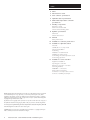
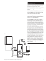
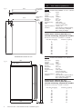
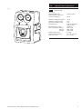
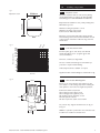
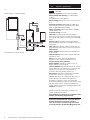
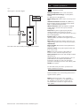
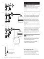
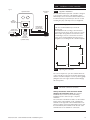
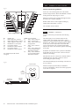
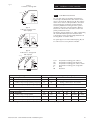
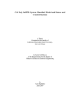
Please read these instructions before installing or commissioning.
Potterton Solar - Solar Thermal Domestic Hot Water System
should only be installed by a competent person.
Please leave these instructions with the user for safe keeping.
Installation Guide
Potterton Solar - Solar Thermal Domestic Hot Water System
© Baxi Heating UK Ltd 2007.
Index
2 Index
3 Introduction to Solar
4 Solar collector specifications
5 Hydraulic station specifications
6 Differential temperature controller
specifications
7 Ancillary components
Expansion vessel
Solar heat transfer fluid
Thermostatic blending valve
8 Cylinder specifications
Unvented
Cistern-fed vented
10 General
Safety information
12 Installation of collector panel sensor
13 Installation of hydraulic station
Parts list
Identification of components
Pipework installation
Positioning
Installation of wall brackets
Installing the safety group
Connecting the solar expansion vessel
Connecting pipework
19 Installation of solar controller
Appliance installation
Opening the controller
Electrical connection overview
General guidelines
230/240V~ connections
Solar gain measurement
Connection of temperature sensors
Control of auxiliary heat input
© BAXI Heating UK Ltd 2007. All rights reserved. No part of this publication may be reproduced
or transmitted in any form or by any means, or stored in any retrieval system of any nature
(including in any database), in each case whether electronic, mechanical, recording or otherwise,
without prior written permission of the copyright owner, except for permitted fair dealing under
Copyrights, Designs and Patents Act 1988.
Applications for the copyright owner’s permission to reproduce or make other use of any part of
this publication should be made, giving any details of the proposed use to the following address:
The Company Secretary, BAXI Heating UK Ltd,The Wyvern Business Park, Stanier Way, Derby DE21 6BF.
Full acknowledgement of author and source must be given.
WARNING: Any person who does any unauthorised act in relation to a copyright work may be
liable to criminal prosecution and civil claims for damages.
2
Potterton Solar - Solar Thermal Domestic Hot Water System
Introduction to Solar
Thank you for purchasing a high quality Potterton Solar
Solar Thermal Domestic Hot Water System.
The sun is the ultimate source of most of our renewable
energy supplies. Energy from the sun is clean and
abundant.
There is a widely held opinion that the UK does not have
enough sun to make solar systems worthwhile. In fact
parts of the UK have annual solar radiation levels equal
to 60% of those experienced at the equator.
However, this energy is not received uniformly
throughout the year. Some 70% of UK annual radiation is
received over the period April to September and 25% is
received in the months of June and July.
Solar water heating technology captures energy from the
sun and transfers this to a water heater to raise the
water temperature therefore reducing the reliance on
fossil fuel energies such as gas, oil and electricity. Up to
60% of a dwelling’s annual hot water requirement can be
provided by a solar water heating system.The balance is
provided by traditional means via a second heat exchanger
connected to a fossil fuel boiler or electrical heating by
electric boiler or immersion heater.
Fig. 1
Potterton Solar - Solar Thermal Domestic Hot Water System
The Potterton Solar water heating system provides all
the principal components required for an efficient solar
water heating system.The sun’s energy is captured by a
series of solar collector panels through which a special
heat transfer fluid is pumped. As the fluid passes through
the collector panels its temperature is raised.The heated
fluid is circulated through a heat exchanger coil in the base
of the solar storage cylinder transferring the heat gained to
the stored water, gradually raising its temperature. The
cooled fluid then returns to the collector panel to be
heated again. Heating by the solar coil is controlled by a
solar differential temperature controller that ensures the
system will only operate when there is useful solar
heating gain at the collector panel. As the sun’s energy
input to the collector panels is variable supplementary
heating by a conventional boiler or electric immersion
heater should be provided.The optional cylinders that
can be supplied with the Potterton Solar package provide
a supplementary heat exchanger coil and immersion
heater as standard.
3
Fig. 2.1
Flow/return
connections
83
1197
Temperature
sensor
pocket
Ø8mm
117
70
1170
Technical data FK8200 “on roof” collector
Gross area:
Net area:
Weight:
Absorber capacity:
Pressure:
Absorption:
Emission:
Stagnation temp:
Glass:
2,02m2
1,84m2
39 kg
1,40 litres
10 bar
95% +
_ 2%
5% +
_ 2%
184°C (Max)
Low-iron solar glass,
tempered 3.2mm thick
Light transmittance: >90.8% +
_ 2%
Insulation:
40mm Rockwool with black facing.
Heat conductivity 0.045W/mK.
Gross density 40-50kg/m3
1730
Mass flow rate [kg/h]
0
50
100
150
200
250
300
350
400
450
500
2.2
Pressure loss [mbar]
0
1
3
6
10
15
21
28
36
45
55
Technical data IDMK in-roof collector
Gross area:
Net area:
Weight:
Absorber capacity:
Pressure:
Absorption:
Emission:
Stagnation temp:
Glass:
2,52m2
2,32m2
54 kg
1,70 litres
10 bar
95% +
_ 2%
5% +
_ 2%
210°C (Max)
Low-iron solar glass,
tempered 3.2mm thick
Light transmittance: >90.8% +
_ 2%
Insulation:
50mm Rockwool with black fleece.
Heat conductivity 0.045W/mK.
Gross density 50-80kg/m3
1130
Pressure loss collector for antifreeze/water mixture (40%/60%) at a
thermal conducting temperature of 50°C.
Pressure loss curve: ∆p = 0,0002x2 + 0,00301x
2104
2058
Temperature sensor
pocket Ø8mm
1228
4
2.1
Solar collector specifications
Pressure loss collector for antifreeze/water mixture (40%/60%) at a
thermal conducting temperature of 50°C.
Pressure loss curve: ∆p = 0,000206x2 + 0,007754x
All dimensions shown in mm
Fig. 2.2
2.0
116
Potterton Solar - Solar Thermal Domestic Hot Water System
Mass flow rate [kg/h]
0
50
100
150
200
250
300
350
400
450
500
Pressure loss [mbar]
0
4
8
12
17
21
26
32
38
43
50
Fig. 3
3.0
3.1
Hydraulic station specifications
Technical data
Dimensions
(Height/Width/Depth)
Flow and return connections
(compression fittings)
Maximum working temperature:
Maximum working pressure:
Pressure Relief Valve setting:
Circulating Pump:
Circulating Pump voltage:
Power consumption Setting 1:
Setting 2:
Setting 3:
Maximum Pump Head:
Maximum Pump Capacity:
Flow meter scale:
Potterton Solar - Solar Thermal Domestic Hot Water System
375/250/190mm
22mm
120°C
6 bar
6 bar
Grundfos UPS 25-60
/ Wilo ST 25/6
230/240 V ~
45W / 45W
68W / 65W
90W / 85W
6 metres
4.5 m3/h / 3.5 m3/h
2 to 15 l/min
5
Differential temperature controller
4.0
Fig. 4
4.1
Housing
Material
Technical data
100% recyclable ABS
Dimensions
L x W x D in mm
weight
175 x 134 x 56
ca. 360 g
Ingress protection
IP40 according to VDE 0470
Electrical values
Operating voltage
230/240V ~ 50 Hz
Interference grade
N according to VDE 0875
Max. conductor
cross-section
240V-connections
2.5 mm2 fine-strand/single-wire
Temperature sensor /
temperature range
PTF6 - 25°C to 200°C
PT1000, 1,000 kΩ at 0°C
Test voltage
4 kV 1 min according to
VDE 0631
Switching voltage
230V / 240V
Capability per one
switch output
1A / ca. 230VA for cos j = 0,7-1,0
Total capability of
all outputs
2A / ca. 460VA maximum
Fuse protection
fine-wire fuse 5 x 20mm, 2A/T
(2 amperes, slow)
Features
Self explanatory, menu driven operation
Adjustable control valves
System monitoring
Energy yield, (solar gain) measurement
Suitable for flat plate and evacuated tube type collectors
Reheat thermostat function
Can be used in a number of system configurations
6
Potterton Solar - Solar Thermal Domestic Hot Water System
5.0
Fig. 5
Expansion vessel
5.1
Ø300mm
Ancillary components
Expansion vessel
Membrane expansion tanks for solar primary heating
circuit. Manufactured according to the Directive PED
97/23/CE (approved noZ-DDK-MUC-02-396876-04).
3/4”
392mm
Butyl membrane suitable for solar primary heating fluid,
DIN 4807-3 approval.
Maximum working temperature +110°C.
Maximum percentage of glycol 50%.
Connection: 3/4” BSP male parallel
Expansion vessel supplied with wall mounting bracket
and self sealing vessel connection that will allow removal
of the vessel for maintenance without losing solar heat
transfer fluid.
Pressure Loss kPa
22
mm
28
mm
Fig. 6.1
200
180
160
140
120
5.2
Solar heat transfer fluid
Pre-mixed (40% glycol / 60% water) Solar thermal
transfer fluid. Based on1,2 - propylene glycol with
corrosion inhibitors.
100
Non-toxic, odourless, bio-degradable.
70
The use of chemical resistant gloves and suitable eye
protection is required when handling.
50
A full safety data sheet is available on request.
40
30
0.2
0.3
0.4 0.5
Fig. 6.2
0.7
Flow l/s
1.0
1.4
2
5.3
92mm
Thermostatic Blending Valve
Can be set to control the hot water delivered to the
user outlets to a safe working temperature enabling the
solar cylinder to store water at a higher temperature.
81mm
22mm
Supplied in 20litre container.Weight of container full - 21kg.
Hot
Cold
60mm
Mix
22mm
Potterton Solar - Solar Thermal Domestic Hot Water System
Connections: 22mm compression
Max working pressure (static): 14 bar
Max working pressure (dynamic): 5 bar
Min working pressure (dynamic): 0.2 bar
Max inlet pressure ratio: 2:1
Min flow required for stable control: 5 l/min
For pressure drop diagram and dimensions see Fig. 6.1
& Fig. 6.2
NOTE: For optimum operation the cold connection must
be taken from a balanced cold water feed.
7
6.0
Fig. 7
Unvented system - schematic diagram
6.0
Cylinder specifications
Unvented
Nominal capacities 190, 210, 250 and 300 litre.
Rating Immersion heater(s) 1 x 3 kW (indirect
models),
2 x 3kW (direct models) @ 240V~.
Outer casing White plastic coated corrosion proofed
steel.
Thermal insulation CFC/HCFC-free (ODP zero)
flame-retardant expanded polyurethane (50mm thick).
GWP 3.1 (Global Warming Potential).
Water container Duplex 2304 (Grade 1.4362 EN
10088) stainless steel.
Pressure testing To 15 bar.
Heat unit Long-life Superloy 825 alloy sheathed
element/s, incorporated into an easily removable heater
plate, should replacement be necessary. Rated 3.0kW @
240V~.
Primary coil (for Auxiliary boiler heating) 22mm
diameter stainless steel. Coil in coil design for improved
performance
Solar coil 25mm diameter stainless steel. Coil in coil
design and large surface area for improved performance.
Note: Indirect twin coil unit shown.
Thermostat
Direct models: Element thermostat adjustable from
10°C to 70°C.
Indirect models: Factory-fitted cylinder thermostat
adjustable to 70°C.
Solar: Factory fitted control pocket suitable for
insertion of solar controller temperature probe.
Factory fitted safety features:
Direct models: Manually re-settable cut-out on
heating element operates at 85°C.
Indirect models: High limit thermal cut-out operates
at 85°C.Wired in series with two-port motorised valve
(supplied) to provide primary over temperature
protection when using auxiliary (boiler) coil.
All models: Temperature and Pressure Relief Valve,
factory set to operate at 10 bar and 90°C.
High limit thermal cut-out operating at 85°C at solar coil
position.Wired in series with the solar differential
temperature controller to provide over temperature
protection if overheating occurs from solar collector panels.
N.B.This must be used in an unvented installation to
comply with the requirements of Building Regulation G3.
Anode Not required.
For full technical and performance specification see
cylinder installation instructions.
The cylinders are unvented so installation must
comply with Building Regulation G3.
Potterton recommend the use of the Santon
Premier Plus Solar unvented cylinders.
The use of other cylinders may not satisfy
the requirements of Building Regulation G3.
8
Potterton Solar - Solar Thermal Domestic Hot Water System
Fig. 8
Vented system - schematic diagram
6.0
6.1
Cylinder specifications
Cistern-fed vented
Nominal capacities 190, 210, 250 and 300 litre.
Rating Immersion heater(s) 1 x 3 kW (indirect
models),
2 x 3kW (direct models) @ 240V~.
Outer casing White plastic coated corrosion proofed
steel.
Thermal insulation CFC/HCFC-free (ODP zero)
flame-retardant expanded polyurethane (50mm thick).
GWP 3.1 (Global Warming Potential).
Water container Duplex 2304 (Grade 1.4362 EN
10088) stainless steel. 40 metres (4 bar) maximum
working head.
Heat unit Tin plated long-life Superloy 825 alloy
sheathed element/s, incorporated into an easily
removable heater plate, should replacement be necessary.
Rated 3.0kW @ 240V~.
Primary coil (for auxiliary boiler heating) 22mm
diameter stainless steel. Coil in coil design for improved
performance.
Solar coil 25mm diameter stainless steel. Coil in coil
design and large surface area for improved performance.
Note: Direct unit shown. Auxiliary heating by immersion heater.
Thermostat
Direct models: Element thermostat adjustable from
10°C to 70°C.
Indirect models: Factory-fitted cylinder thermostat
from 10°C to 70°C.
Solar: Factory fitted control pocket suitable for
insertion of solar controller temperature probe.
Safety features Thermostats with manually resettable
thermal cut-out.
High limit thermal cut-out operating at 85°C at solar coil
position.Wired in series with the solar differential
temperature controller to provide over temperature
protection if overheating occurs from solar collector panels.
Anode Not required.
For full technical and performance specification see
cylinder installation instructions.
Detailed installation and commissioning instructions are
supplied with the cylinders.
Note: The Potterton Solar is also compatible
with cylinders configured for solar DHW systems.
For installation and specification details refer to
the manufacturers instructions supplied with the
solar cylinder.
Potterton Solar - Solar Thermal Domestic Hot Water System
9
7.0
7.1
General
Safety information
In order to reduce the number of deaths and major
accidents attributable to work at height, the Health and
Safety Executive has introduced comprehensive
regulations and guidance that should be followed by all
businesses working at height.
We consider in the following paragraphs some of the
main features of the regulations and guidance.This is,
however, only a limited summary and it is recommended
that all businesses planning on undertaking solar water
heating installations obtain a copy of the regulations and
guidance issued by the Health and Safety Executive and
carefully consider the contents.
The regulations and guidance state that you are required
to carry out a risk assessment for all work conducted at
height and to put in place arrangements for:
• Eliminating or minimising risks from work at height.
• Safe systems of work for organising and performing
work at height.
• Safe systems for selecting suitable work equipment.
• Safe systems for protecting people from the
consequences of work at height.
The regulations and guidance highlight a
hierarchy for safe work at height:
• Avoid the risk by not working at height if practicable.
• Prevent falls, where it is not reasonably practicable
to
avoid work at height; you are required to take suitable
and sufficient steps to prevent the risk of a fall
including selecting the most suitable work equipment
(in accordance with the regulations).
• Mitigate the consequences of a fall; where the risk of
a person or object falling still remains, take suitable
and sufficient measures to minimise the distance and
consequences of any fall.
Collective protection measures, such as guard rails on
scaffold, should be given priority over personal protection
measures, such as safety harnesses.
Within the regulations’ framework, you are required to:
1) Assess the risk to help you decide how to work safely.
2) Follow the hierarchy for safe work at height (i.e. avoid,
prevent and mitigate).
3) Plan and organise your work properly, taking account
of weather conditions and the possibility of emergencies.
4) Make sure those working at height are competent.
5) Make use of appropriate work equipment.
6) Manage the risks from working on or around fragile
surfaces and from falling objects.
7) Inspect and maintain the work equipment to be used
and inspect the place where the work will be carried out
(including access and egress).
When preparing to install a solar water heating system, it
is required that you perform a risk assessment in relation
to work at height and plan how you will organise your
work, taking into account the site, the weather conditions
and the experience and competence of colleagues or
contractors who may be working at height with you.
10
Potterton Solar - Solar Thermal Domestic Hot Water System
7.0
General
Risk Assessments
The HSE has published a number of very useful free
publications that advise how to undertake risk assessments.
Two of these that you should obtain are:
Five Steps to Risk Assessment.
A Guide to Risk Assessment Requirements.
The five steps outlined in the HSE leaflet are:
Step 1: Look for the hazards
This will mean looking at the site and identifying
significant hazards.These could be features such as a
steep roof, a fragile surface where the collectors may be
mounted, uneven ground or obstructions where access
to the roof might be required.
Step 2: Decide who may be harmed and how
This might mean considering the particular risks that
young workers or trainees might face and thinking about
the residents of the household or visitors who could be
hurt by your activities.
Step 3: Evaluate the risks and decide which precautions
should be made You should consider how likely it is that
each hazard will cause harm, decide which precautions
you might take and then assess, after you have taken
those precautions, whether the remaining risk will be
high, medium or low.Where you identify remaining risks,
you should consider which further action you could take
to control the risks so that harm is unlikely.
Step 4: Record your findings
If you have fewer than five employees you do not need
to write anything down, though it is useful to keep a
written record of what you have done. If you employ five
or more people you must record the significant findings
of your assessment.You must also tell your employees
about your findings.You need to be able to show that a
proper check was made, that you considered who might
be affected, that you dealt with all the obvious significant
hazards, that the precautions you propose are reasonable
and that the remaining risk is low.
Step 5: Review your assessment if necessary
Each solar water heating installation may bring its own
challenges and present its own particular hazards.You
should therefore be careful not to rely on a “standard”
risk assessment for installing a solar water heating system
in a house, but review the particular hazards for each
new situation.The issue of work equipment must be
considered, but at the preparation stage you should
consider where scaffold or other access equipment might
be positioned and look out for any obvious obstacles to
this, such as a conservatory or porch.
In addition to the risks associated with work at height,
you should also consider the risks associated with lifting
and carrying solar collectors, using electric drills and using
blow lamps or blow torches for soldering.This is not an
exclusive list and so you should consider all aspects of
the proposed installation to assess whether there are
additional risks that need to be taken into account.
Potterton Solar - Solar Thermal Domestic Hot Water System
11
8.0
Fig. 9
Installation of collector panel sensor
The Collector panel temperature sensor should be
installed in the sensor pocket nearest to the collector
array flow. It should be secured in pocket by inserting
through the rubber gland provided. All materials used for
installing temperature sensors (sensor element, conducting
compound, cables, sealing and insulating materials) must
be suitably temperature resistant (up to 250°C).
NOTE: “On-roof” type panel shown.The “In-roof” type
panel has connections on the top edge of the collector
(see Fig. 2.2) and the sensor pocket is located behind the
left hand connection.
12
Potterton Solar - Solar Thermal Domestic Hot Water System
9.0
Fig. 10 (Diagrams not to scale)
9.1
Parts list
Before commencing the installation check all listed
components are contained in the following cartons.
3
1
Installation of hydraulic station
Hydraulic Station carton:
1. Hydraulic pump station with insulation incorporating
wall mounting bracket.
2
2. Solar differential temperature controller.
4
3. Safety group, comprisingPressure relief valve, pressure gauge and fill &
drain valve.
4. 22mm compression fitting (4 off).
5
5. Re Heat sensor. (Optional order part no. 5122234)
6. Solar Gain Module comprisingElectric flowmeter and return temperature sensor.
(Optional order part no. 5122235)
7. Sensor extension cable (13m) (not shown).
6
Ancillary component carton:
8. Solar expansion vessel complete with mounting bracket
and strap assembly.
9. Expansion vessel connecting hose.
10. Expansion vessel self sealing connection.
11. Thermostatic Blending valve.
8
12. 2m insulated flexible steel hoses for connection
to collectors
9
12
11
10
Potterton Solar - Solar Thermal Domestic Hot Water System
13
9.0
Fig. 11
9.2
Installation of hydraulic station
Identification of components
The main components of the hydraulic station are:
1
3
2
4
6
5
–
Two isolating valves (Fig. 11, Item 1 & 2) with integral
thermometers which display the solar primary flow
and return temperatures.
–
A safety group (Fig. 11, Item 3, supplied unconnected),
which protects the solar primary circuit.The pressure
relief valve and pressure gauge are integrated in the
safety group.
–
A non-return valve in both feed and return prevents
the possibility of gravity circulation in the solar
primary circuit.
–
A solar circulation pump (Fig. 11, Item 4).
–
A flow meter with fill & drain valve and shut-off valve
(Fig. 11, Item 5).
–
An air separator.
The heat transfer fluid is circulated by the solar circulation
pump integrated in the hydraulic pump station (Fig. 11).
The hydraulic station has a solar differential temperature
controller (Fig. 11 Item 6) integrated into the front
insulation moulding.This is pre-wired to the solar pump.
14
Potterton Solar - Solar Thermal Domestic Hot Water System
9.0
Fig. 12
9.3
See Fig. 12
5
4
3
2
Installation of hydraulic station
1
1
2
3
4
5
6
7
8
9
Solar cylinder
Collector temperature sensor lead
Solar primary flow (from collector)
Solar collector panel(s)
Solar primary return (to collector)
Solar primary flow (to cylinder)
Solar primary return (from cylinder)
Solar differential temperature controller
Cylinder temperature sensor lead
9.4
8
7
6
9
Pipework installation - general
The collectors, the hydraulic station and the solar cylinder
(Fig. 12, Item 1) must be connected with hard soldered
copper pipes, compression fittings or multifit accessory
flexible steel tube and insulation 5122238.
N.B. Plastic pipes MUST NOT be used.
Connections supplied are suitable for pipe diameters of
22mm. However for short pipe runs (up to 10m) the use
of 15mm diameter pipe is acceptable.
In solar heating systems, use only pipes and fittings made
from copper, brass, bronze brass or stainless steel.
Compression fittings only must be used.
All connections and joints must be resistant to
temperatures of up to 150°C and resistant to glycol.
The height difference between the highest point in the
pipework (collector) and the hydraulic station may be a
maximum of 15m (this is called the ‘static height’). If the
static height is greater than 15m a larger expansion vessel
may be required.
If any pipe sealants are used these should be resistant to
glycol and be able to withstand temperatures of up to
150°C.
9.4.1 Earthing pipework
All solar primary pipework between the solar collectors,
hydraulic station and solar cylinder must be earth bonded
to avoid electrical potential differences.This work must
be carried out by a qualified electrician.
Fit earthing clamps to the solar primary flow and return
pipes and connect the earth clamps to the earthing system
of the property using an earth bonding cable of min. 6mm2
diameter.
Potterton Solar - Solar Thermal Domestic Hot Water System
15
9.0
Installation of hydraulic station
9.4.2 Venting the pipework
Fig. 13
The Potterton Solar hydraulic station the component
includes an air collector/separator and bleed point so an
automatic air vent is not necessary. Any section of solar
pipework that falls and rises again should be fitted with
an additional air vent valve to relieve any trapped air
which may cause air locking in the system.The automatic
air vent and isolating valve used must be compatible with
solar primary systems, i.e. be resistant to glycol and
temperatures up to 180ºC.
9.4.3 Insulating the pipework
External pipework should be insulated with high
temperature resistant materials and be protected against
UV degradation. Internal pipework, especially through
unheated spaces such as a loft space, should also be
insulated with high temperature resistant materials.
Mark the outside of any insulation to identify the flow
and return pipes.
The Potterton Solar panels are supplied with 2x2m pre
insulated flexible stainless steel tubes. Additional lengths
(30m) of stainless steel flexible tubes and high
temperature insulation can be supplied.
16
Potterton Solar - Solar Thermal Domestic Hot Water System
9.0
Fig. 14
Installation of hydraulic station
9.5
Installing the hydraulic station - positioning
9.6
Installing the wall brackets and hydraulic
station
It is usual to install the hydraulic station and solar
differential temperature controller near to the solar
cylinder. However this does not have to be the case, the
hydraulic station can be installed anywhere convenient
on the solar primary pipework although adequate access
will be necessary for commissioning and maintenance.
The solar differential controller should also be accessible
for system operational monitoring. If not in close
proximity to the solar cylinder it will be necessary to
extend the solar cylinder temperature sensor cable,
refer to section 10.6 for details of how to do this.
It is recommended that the upper mounting bracket
of the hydraulic station is positioned approx. 1600 to
1700mm above the floor level for ease of access and
operation of the controls, see Fig. 14.
When choosing the site for the hydraulic station provision
of a discharge pipe from the safety group and the location
of the solar expansion vessel must be considered.
Fig. 15
1
2
4
6
5
Remove the front insulation moulding (Fig 15. Item 1)
by pulling forward whilst holding the solar differential
controller moulding (Fig 15. Item 2) in place. carefully
remove the solar differential controller mounting by
pulling forward and disconnect the pump cable connector
(Fig 15. Item 3). Place the hydraulic assembly on the wall
at the desired location and mark the fixing positions
through the holes in the mounting brackets. Remove the
hydraulic assembly from the mounting brackets (Fig 15.
Item 4) and remove rear insulation moulding (Fig 15. Item
5). Drill and plug the mounting positions and screw the
mounting brackets into position. Push the rear insulation
moulding over the wall brackets and refit the hydraulic
assembly (Fig 15. Item 6) to the mounting clips on the
wall brackets.
4
3
Potterton Solar - Solar Thermal Domestic Hot Water System
17
Fig. 16
1
3
9.0
2
4
5
3
1
2
Fig. 18
Return
to
panel
3
Connecting the solar expansion vessel
Mount the solar expansion vessel (Fig 17 Item 1) adjacent
to the hydraulic station (Fig 17 Item 2) so that the vessel
can be connected to the vessel connection of the safety
group (Fig 17 Item 3) using the flexible pipe (Fig 17 Item
4) supplied. (Note: Solar expansion vessel, mounting
bracket, self sealing connection and flexible pipe are
supplied in the Ancillary Components kit).The vessel
must be mounted as shown (connection to top) and
securely supported using the wall bracket supplied.The
self sealing vessel connection should be screwed onto
the vessel connection before connecting the flexible pipe
(Fig. 17 Item 5).
The charge pressure at the solar expansion vessel should
be adjusted such that when not under load the charge
pressure is 0.4 bar above the static system head (the
height of the top of the collector panels above the
hydraulic station). A one metre head represents 0.1 bar.
However, the charge pressure should be at least 1.2 bar.
The maximum static system head is 15m (1.5 bar).
Connecting pipework
Connect the flow and return pipes to the collectors and
to the cylinder via compression fittings (Fig 18 Item 1).
Fittings are for 22mm o/dia pipe. Support the hydraulic
assembly when tightening connections.
Return
from
cylinder
4
18
9.8
9.9
Flow
to
cylinder
Fig. 19
Installing the safety group
DO NOT replace the solar expansion vessel with either
a potable water expansion vessel or boiler sealed system
vessel.
2
1
9.7
Connect the safety group (Fig 16 Item 1) with the gasket
(Fig 16 Item 2) enclosed to the connection on the
hydraulic station return isolating valve assembly (Fig 16
Item 3).
Fig. 17
Flow
from
panel
Installation of hydraulic station
Run a pipe (Fig 18 Item 2) from the exit opening in the
pressure relief valve (Fig 18 Item 3) to a suitable
container (Fig 18 Item 4) and secure it.
Return to hydraulic station
Return from cylinder
9.9.1 Installing a drain valve
Install a device for draining the solar heating system
(tee piece with drain valve, Fig. 19) into the flow and
return at the lowest point in the solar heating system.
Flow to cylinder
9.9.2 Connecting the solar cylinder
For detailed installation instructions refer to the
installation instructions supplied with the solar cylinder.
Potterton Solar - Solar Thermal Domestic Hot Water System
10.0
Fig. 20
Hydraulic Station
Solar panel
sensor
Solar
differential
controller
L
N
E
230V/240V~
Mains supply
Pump
pre-wired
(mounted on
hydraulic station)
Appliance installation
The solar differential temperature controller is designed
to be mounted on the front of the hydraulic station.
Alternatively it can be removed from the insulation and
be wall mounted (see panel below). In the case of wall
mounting the pump cable may need to be lengthened.
Alternative mounting option
Terminal block
for extending
collector sensor
Double pole
isolating switch
10.1
Installation of solar controller
Cylinder
sensor
In the case of wall installation proceed in the
following way:
Drill installation holes according to the dimensions
shown below. Screw in two upper screws up to 6 mm
distance. Open the appliance as described in section
10.2 and hang it onto two screws. Now two lower
screws can be mounted.Tighten all screws. Do not
overtighten to avoid damage to the controller backplate.
126mm
84mm
118mm
10.2
Opening the controller
No tools are required to open the controller.The front
of the controller is secured by two latches which engage
with the controller backplate. It can be opened by gently
pulling the lower side edges outwards and then hinging
the front upwards.
10.3
Electrical connection overview
Always disconnect from the mains before
opening the controller cover. The electrical
installation must conform to all current Wiring
Regulations and be carried out by a competent
electrician.
The connection of all electrical cables is to the terminal
block located on the backplate of the controller.The
terminals on the right side of the terminal block are for
extra low voltage connections (temperature sensors and
flow transmitters).The terminals on the left side of the
terminal block are for 230/240 V~ connections.
Potterton Solar - Solar Thermal Domestic Hot Water System
19
10.0
Fig. 21
General connection guidelines.
WMM
PE
T1
T2
L
N
A1
N
A2
N
A3
N
T3
T4
T6
low voltage area
Earthed wire
Mains supply live conductor
Mains supply neutral conductor
Switch output to solar pump
Neutral wire to solar pump
Live switch output 2
Neutral wire switch output 2
Live switch output 3
Neutral wire switch output 3
WMM
T1
T2
T3
T4
T5
T6
For switch functions A2 and A3
see Fig. 23
Flow transmitter
Temp.- sensor collector 1
Temp.- storage tank 1
Temp.- sensor collector 2/
storage tank 2
Temp.- sensor collector
return
Temp.- sensor thermostat
or for 2nd temperature
differential controller
Temp.- sensor antifreeze
or for 2nd temperature
differential controller
Fig. 22
Hydraulic Station
Solar
differential
controller
L
N
E
Double pole
isolating switch
Solar coil
over-temp
cut-out
230V/240V~
Mains supply
20
In the case of all connecting wires the outer sheath
should be stripped back to 80mm.The individual conductor
sleeving should be stripped approx. 10mm.
Cables are inserted in the controller through knockouts
provided in the controller backplate.
Flexible cables must be secured against straining by
suitable strain relief bushes or devices.
The controller must be earthed.
T5
mains voltage area
PE
L
N
A1
N
A2
N
A3
N
Installation of solar controller
Potterton Solar - Solar Thermal Domestic Hot Water System
10.4
230/240V~ connections
For 230V connections you must follow the following
points:
The mains supply to the controller should be via a
suitable double pole isolating switch with a contact
separation of at least 3mm in both poles. Additionally for
unvented solar cylinders the controller should be wired
via the solar coil over temperature cutout such that
power is interrupted to the controller and hydraulic
station in the event of the unvented cylinder overheating
(see Fig. 22).
Controllers are intended for the operation in 230/240V~
/50Hz mains. Any motorised valves connected must be
suitable for this voltage.
All earth wires must be connected to terminals marked
with PE. Any bare wire earth conductors must be
sleeved with green/yellow sleeving.
The neutral terminals (N) are electrically connected and
are not switched.
All switch outputs (A1, A2 and A3) are 230/240V~
closers. If potential-free contacts are needed, appropriate
accessories are required.
Fig. 23
T
T
Tcoll
C
Collector
10.5
Storage tank
For solar gain (energy productivity) measurement it
is necessary to fit the flowmeter and collector return
sensor as shown in the diagram in Fig. 23.The collector
return sensor must be securely attached to the return
pipework using the securing tiles supplied and then
covered by insulation.The solar gain of the system is
calculated
on the basis of the temperature difference
T
between the collector flow and return and the solar
primary circulation flow rate.
The function must be switched “on” when commissioning
the Solar Differential Temperature Controller. Refer
T
to the Potterton Solar “Commissioning, Maintenance &
Servicing Guide”
for further details.
S
P
Tst
FM
Tret
2:
Type
C
1 collector, 2 storage tanks
with 2 pumps
S
C
Tcoll
T
Storage tank1
Solar Gain measurement
Sto
Tth
Storage tank2
For System Types 2 and
4 the additional pump (P2) can
T
be ordered as an accessory, Part No. 5129362.
T
Tth
F
Collector
C
Installation of solar controller
10.0
Type 0:
1 collector, 1 storage tank
Tst1
Tst2
FM
P2
P1
Tret
T
Type 4:
2 collectors, 1 storage tank
with 2 pumps
Collector 1
Tcoll2
Tcoll1
Tcoll
Tth
Tret
Tst
P
FM
Storage tank1
Tth
P1
Tst
P2
FM
Tret
Type
System type
Description
A1
1 collector array, 2 storage cylinder (pump-pump)
P1
0
1 collector array, 1 storage cylinder
4
2 collector array, 1 storage cylinder (pump-pump)
2
System type
Type
Description
2
1 collector array, 2 storage cylinder (pump-pump)
0
4
P1
P1
T1
A2
point
point
point
point
collector
thermostat
collector return
storage tank
A3
-
Cooling or thermostat or diff. controller
P2
Cooling or thermostat or diff. controller
P2
Cooling or thermostat or diff. controller
Sensor terminal designation (see Fig. 21)
T2
T3
Tst1
Tst2
Tcoll1
Tst1
2 collector array, 1 storage cylinder (pump-pump)
Tcoll1
Tst1
T4
T5
-
Tret
Tth/TDiff1
Tcoll2
Tret
Tth/TDiff1
NOTE:The solar gain flowmeter must be connected to sensor terminals marked WMM (see Fig. 21).
Potterton Solar - Solar Thermal Domestic Hot Water System
measuring
measuring
measuring
measuring
Output terminal designation (see Fig. 21)
1 collector array, 1 storage cylinder
Tcoll1
Temperature
Temperature
Temperature
Temperature
Pump
Flowmeter
Tret
Tth/TDiff1
T6
Tfr TDiff2
Tfr TDiff2
Tfr TDiff2
21
Fig. 24
10.0
Block Wiring Schemes
A. Potterton Solar in conjunction with auxiliary heating by boiler
10.6
- no reheat control by solar controller.
3A Fused Supply
Boiler Terminal Strip
L
N
E
1
2
3
1
2
3
7
10
1
2
3
L
PL
N
1
4
2
3
5
6
7
8
9
10
3
3
2
10
1
5
E
G/Y
BL
BR
GR
OR
1
L
N
E
1
2
3
2
3
2
2
N
G/Y
BL
Room Stat
9
1
5
4
BR
GR
OR
L
3
2
2
11
12
PE
L
N
A1
N
See Fig. 20
T1
T2
T4
A1
WMM
11
Solar Differential Controller
3
1
2
E
Installation / cabling of temperature sensors:
Mount the sensors in the pockets provided in the
collector and storage tank. When installing into the
collector panel sensor pocket the sensor should be
secured by inserting through the rubber gland provided.
2
3
N
E
The wires of the temperature sensors can be lengthened.
Up to 15m long you need a 2 x 0,5mm2 cross-section, up
to 50m 2 x 0,75mm2. In the case of long connections
(collector) shielded extension lead must be used.
DO NOT run sensor leads adjacent to mains carrying
voltage conductors (at least 50mm separation is
recommended).
CH Pump
CH 2 Port Valve
Solar
Controller
L
6
Terminal Box (Not supplied)
DHW 2 Port Valve
9
1
DHW ON CH ON
7
N
PE
12
E
Solar Pump
Solar O/Temp Cutout
Note: For Boilers without Pump over run connect CH Pump Live Supply to
5
B. Potterton Solar in conjunction with auxiliary heating by boiler - reheat
control via solar controller.
3A Fused Supply
Boiler Terminal Strip
N
E
L
PL
N
E
SL
L
N
1
2
1
2
3
1
4
2
3
5
1
2
1
6
1
2
3
5
6
7
8
9
10
7
10
3
3
2
10
1
5
1
2
E
G/Y
BL
BR
GR
OR
3
3
2
G/Y
BL
6
1
5
4
BR
GR
OR
L
CH 2 Port Valve
3
8
2
11
12
7
2
PE
L
N
A1
N
A3
N
2
3
N
E
A1
See Fig. 20
T2
T4
T5
WMM
11
Solar Differential Controller
1
8
3
1
2
E
N
PE
12
E
Solar Pump
C. Solar Cylinder with auxiliary heating by immersion heater.
Boiler
Immersion
13 Amp Fused Supply
L
N
E
L
N
E
1
2
3
4
5
6
1
2
3
4
5
6
7
3
8
2
11
12
PE
L
N
A1
N
8
9
Relay
A3
10
Terminal Box (Not supplied)
A1
See Fig. 20
N
T1
T2
T4
T5
WMM
1
8
3
1
2
E
Solar O/Temp Cutout
22
A3
N
4
7
7
5
6
1
5
CoM
No
L
N
E
Auxiliary Immersion Heater Relay
11
N
PE
12
E
Solar Pump
Solar Differential Controller
The reheat sensor cable should be connected to
terminals T5 of the solar controller and the sensor
element be inserted into the controls pocket at the
auxiliary heater level.
N.B.The maximum switching current of the controller
is 2A so if switching an electrical immersion heater this
MUST be done via a relay (see Fig. 24 Black Wiring
Scheme C) order accessory code No. 5122765.
If using a boiler for auxiliary input, the output from the
reheat function should be integrated into the boiler
control circuit.
Solar O/Temp Cutout
3 Amp Fused Supply
Control of Auxiliary heat input
When using the reheat function the operation of the
auxiliary heat input device can be controlled via output
A3 from the controller.
CH Pump
T1
Sensors MUST NOT be connected to the 230/240V~
terminals.
10.7
Terminal Box (Not supplied)
DHW 2 Port Valve
Cylinder Auxiliary Controls
Temperature sensors are connected according
to the appropriate terminals, refer to Fig 21.
The sensors are polarity free.
Programmable Room Stat
L
4
Connection of temperature sensors
The controller uses precise platinum temperature
sensors type PT1000.The controller is supplied with
3 sensors. The sensor with black silicone
sheathing must be used for the solar panel
sensor.
Programmer
SL
5
4
Cylinder Auxiliary Controls
6
E
Installation of solar controller
Immersion Heater
Potterton Solar - Solar Thermal Domestic Hot Water System
10.0
D. Auxiliary heating by boiler with 3 port mid position valve system
- no reheat control by solar controller.
3A Fused Supply
Boiler Terminal Strip
L
N
E
L
1
2
3
1
2
3
4
8
5
7
1
2
3
PL
N
1
1
4
2
3
5
6
7
8
9
3
3
2
10
NOT USED
E
G/Y
BL
BR
GR
2
3
2
N
G/Y
L
N
E
1
2
3
2
11
12
N
A1
N
1
3
1
2
E
8
7
6
OR
2
9
7
5
4
BL
WH
GR
OR
L
See Fig. 20
T1
T2
T4
2
3
N
E
CH Pump
A1
11
WMM
N
PE
12
E
- reheat control by solar controller.
Boiler Terminal Strip
3A Fused Supply
L
N
E
1
2
3
1
2
3
4
8
5
7
1
L
2
3
PL
N
E
SL
1
4
2
3
5
6
7
8
9
3
3
2
5
NOT USED
E
G/Y
BL
BR
GR
10
L
N
1
2
1
2
1
9
G/Y
OR
2
9
7
5
4
BL
WH
GR
OR
L
3
6
2
11
12
8
2
PE
L
N
A1
N
A3
N
2
3
N
E
CH Pump
3 Port Mid Position Valve
A1
See Fig. 20
T1
T2
T4
T5
WMM
Solar Differential Controller
2
E
The Warranty only applies to equipment and controls
supplied with the Potterton Solar System.
Terminal Box (Not supplied)
DHW 2 Port Valve
3
1
The various ancillary equipment manufacturers should be
consulted to confirm the correct operation of their
products within the system.
Programmable Room Stat
5
Cylinder Auxiliary Controls
3
Live
Neutral
Earth
Pump Live
Switched Live
Green and Yellow
Blue
Brown
Grey
Orange
White
Potterton accept no liability for any loss or damage
arising from any errors or omissions that may be
inadvertently contained within these diagrams.
E. Auxiliary heating by boiler with 3 port mid position valve system
6
-
These diagrams are presented for guidance only, terminal
numbers may differ between different manufacturers
equipment.
Solar O/Temp Cutout
1
L
N
E
PL
SL
G/Y
BL
BR
GR
OR
WH
The wiring schemes assume the use of an unvented Solar
DHW cylinders.
Solar Pump
Solar Differential Controller
Solar
Controller
L
DHW ON DHW OFF CH ON
Terminal Box (Not supplied)
3 Port Mid Position Valve
Room Stat
PE
10
L
2 Port Valve
9
3
SL
5
Cylinder Auxiliary Controls
6
Key to abbreviations:
Programmer
E
Installation of solar controller
11
N
PE
12
E
Solar Pump
Solar O/Temp Cutout
Potterton Solar - Solar Thermal Domestic Hot Water System
23
All descriptions and illustrations provided in this leaflet have been
carefully prepared but we reserve the right to make changes and
improvements in our products which may affect the accuracy of the
information contained in this leaflet. All goods are sold subject to
our standard Conditions of Sale which are available on request.
Potterton
A Trading Division of Baxi Heating UK Ltd, a division of Baxi Group.
Brooks House, Coventry Road,Warwick. CV34 4LL
After Sales Service and Technical Enquiries 08700 603261
Our contact centre is open Monday to Friday 8am to 6pm,
Weekends and Bank Holidays 8.30am to 2pm.
We are closed Christmas Day and New Years Day.
Website www.potterton.co.uk
© Baxi Heating UK Ltd 2007.
Comp No 3600 5982 - Issue 1 - 5/07