1
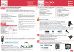
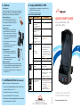
1. SatDOCK-G Installation Set Up 2. Installing SatDOCK-G Cradle Connecting Microphone: • The microphone should be connected to the HFI and then recessed up the door pillar or similar to a head height location close to the driver • Care should be taken to avoid wind or high noise environments • Avoid crimping or damaging the microphone cable during installation Bluetooth Device (Optional) 9555 Handset Antenna Plug EJECT Button Mini USB Data Port 1. Remove base plates by loosening wing nut Intelligent Handset c 7 8 * 0 BEAM 3 5 4 6 9 # iridium SatDOCK Ringer Track Bluetooth 2. Affix other base to SatDOCK-G with M4 screws 3. Rejoin the two bases using the arm Considerations: • Affix the base plate in a location that allows easy access & does not obstruct driver • Allow sufficient room to easily run cables from theSatDOCK-G • ONLY use the M4 screws (supplied) to affix the base to the SatDOCK-G to avoid any damage • For wall mounting use the RAM Bracket with both bases parallel to each other • Tighten wing nut on the bracket to securely hold the SatDOCK-G • Avoid making any sharp bends in the antenna cable when determining the cable route • The fixed cables from the SatDOCK-G should never be extended, Antenna cables must be approved ok 2 1 Mute ALERT Privacy Handset 3. Installation Iridium Antenna (TNC Female) • DO NOT route cables near areas of intense heat • DO NOT pull or strain the cables from the SatDOCK-G GPS Antenna (SMA Female) Connecting to Power: • Connect AC power Adaptor, or DC Cable Lead (9-32V DC input > 25 watts) Horn Alert Connecting to the Antennas: • Only certified cables within the Iridium specification should be used • Ensure antenna cables are routed avoiding any sharp bends in the cable • The antenna should always be installed with clear line of site to the sky Alert Loop (IN / OUT) SPK07 Microphone SatDOCK-G USB Data Port: • The SatDOCK-G has an integrated USB Data Port on the rear. Drivers for this USB port can be download from http://www.beamcommunications.com/support/9555sdg GME Speaker INSTALL POWER: BLACK = 0V Ground to negative Battery. RED + VIN wire to the vehicle + Battery (3A fuse). YELLOW Acc (On/Off sense) to behicle acc/key, or on/off switch (1A fuse). If not required, this YELLOW wire MUST be connected to +VIN (RED WIRE) 4. MIC / Audio Connections WARNING: Your Iridium 9555 Handset requires firmware HT10001 or greater. To check your firmware version on your Iridium 9555 handset press “Menu” then navigate to “Setup” then “Phone Information”. For more information and 9555 Handset firmware downloads visit: http://www.beamcommunications.com/support/SatDOCK-G 9555 NOTE: For Data operation the USB port on the Iridium 9555 handset must not be used whilst docked in the cradle. Please use the USB port located on the bottom of the 9555 cradle. Installing Speaker: •Mount the speaker underneath the seat or other location that avoids the speaker facing the microphone •If feedback occurs upon testing try redirecting the speaker or locate in another location. MIC MIC Speaker Speaker 5. Inserting & Ejecting 9555 Handset Inserting: 1. Remove rubber grommet on back of 9555 antenna connection 2. Ensure 9555 handset is turned off 3. Ensure there is no foreign object in the cradle 4. Place the 9555 in the cradle with the base in first 5. The base connector should line up with the base of the 9555 6. Press EJECT button and phone at the same time to securely lock the phone in the docking station. 1. Place 9555 on the base of the cradle & push into the cradle 2. Push EJECT and phone at the same time 1. Firmly press ‘Eject’ Button 2. Release the phone Ejecting: To remove the 9555 handset from the cradle FIRMLY press the “Eject” button located on the top of the cradle (see diagram).