1
HP-555G
Nov. 1998
HP-555G
SERVICE NOTES
First Edition
ROLAND PIANO DIGITAL
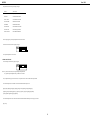
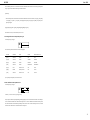
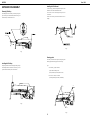
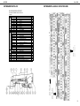
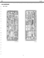
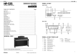
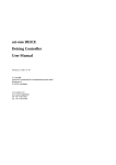
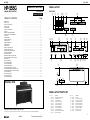
PANEL LAYOUT
FRONT VIEW
p q w
Issued by RJA
TABLE OF CONTENTS
Page
GENERAL VIEW
........................................................................................................... 1
PANEL LAYOUT
PANEL LAYOUT PARTS LIST
SPECIFICATIONS
EXPLODED VIEW
PARTS LIST OF EXPLODED
PARTS LIST
CHECKING THE VERSION NUMBER
HOW TO UPDATE THE FLASH MEMORY
TEST MODE
STAND ASSEMBLY
STAND EXPLODED VIEW
STAND PARTS LIST
STAND EXPLODED VIEW
STAND PARTSLIST
REPLACING FDD
PEDAL UNIT EXPLODED VIEW
CONNECT BOARD PARTS LIST
CONNECT BOARD CIRCUIT DIAGRAM
KEYBOARD DISASSEMBLY
KEYBOARD PARTS LIST
KEYBOARD PA-4A88-C2 CIRCUIT BOARD
KEYBOARD PA-4A88-C2 CIRCUIT DIAGRAM
BLOCK DIAGRAM
CIRCUIT BOARD (MAIN)
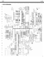
CIRCUIT DIAGRAM (MAIN)
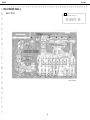
CIRCUIT BOARD (PANEL L)
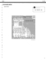
CIRCUIT BOARD (PANEL R)
CIRCUIT DIAGRAM (PANEL L / PANEL R)
CIRCUIT BOARD (FRONT JACK, ANALOG ,INLET)
CIRCUIT DIAGRAM (FRONT JACK, ANALOG ,INLET)
CIRCUIT BOARD (MIC)
CIRCUIT BOARD (LCD B)
CIRCUIT DIAGRAM (MIC)
CIRCUIT DIAGRAM (LCD B)
........................................................................................................... 1
........................................................................................................... 1
........................................................................................................... 2
........................................................................................................... 3
........................................................................................................... 4
........................................................................................................... 4
........................................................................................................... 8
........................................................................................................... 8
........................................................................................................... 9
........................................................................................................... 15
........................................................................................................... 17
........................................................................................................... 18
........................................................................................................... 19
........................................................................................................... 20
........................................................................................................... 20
........................................................................................................... 21
........................................................................................................... 21
........................................................................................................... 21
........................................................................................................... 22
........................................................................................................... 23
........................................................................................................... 23
........................................................................................................... 24
........................................................................................................... 25
........................................................................................................... 26
........................................................................................................... 27
........................................................................................................... 28
........................................................................................................... 29
........................................................................................................... 30
........................................................................................................... 31
........................................................................................................... 32
........................................................................................................... 33
........................................................................................................... 33
........................................................................................................... 34
........................................................................................................... 34
er
Balance
Accomp
t
Tone
Keyboard
Function
Brilliance
Mellow
Piano
E.Piano
Harpsi
Vibes
Pianist
Split
Key Touch
Organ
Strings
Choir GS Tones
Bright
Volume
Min
i
Reverb
Max
Chorus
Lower
y
o !0
!1
u
!4
!2
u
!4 t
y
Disk
Composer
Rhythm
1
2
3
4
Value
Metronome
Song
Beat
Tempo
Exit
Menu
Reset
Transpose
Stop
Play
Rec
Bwd
Fwd
Enter
t
!3
t
t
!4
!5 !6 !7 !8
!9
Count In
Marker
Clear
A
B
Repeat
GENERAL VIEW
!4
u
@0
PANEL LAYOUT PARTS LIST
Copyright © 1998 by ROLAND CORPORATION
All rights reserved. No part of this publication may be reproduced in any form without the written permission of ROLAND CORPORATION.
No.
p
q
w
e
r
t
y
u
i
o
!0
Pno.
00671556
00346178
22485192
22245194
32225353
00900145
00900156
00900167
00900178
01346390
01121689
Part Name
SLIDE POT. EWANNKX10B14
SLIDE POT. RS30111CA
I S-KNOB S BLK/LCG
POT DUST COVER M 1H
I S-ESCT SX1V BLK L=30
D S-KEYTOP SD1H BLK
D S-KEYTOP SD2H BLK
D S-KEYTOP SD3H BLK
D S-KEYTOP SD4H BLK
HP-535 ISOLATOR LED SPONGE
LED SPR-325MVWT31
No.
!1
!2
!3
!4
!5
!6
!7
!8
!9
@0
Pno.
71013990
01346201
01125901
00900189
22495340
22495312
01013023
00900190
01341956
01011923
Part Name
LCD UNIT
HP-535 DISPLAY COVER
D S-KEYTOP SX1H-A BLK
D S-KEYTOP SX1H BLK
D S-KEYTOP MX1H DWG
D S-KEYTOP MD1H MCG
D S-KEYTOP SD1H DRD
D S-KEYTOP SX2H BLK
FDD MF355F-3252MG
ESCUTCHEON FDD
1
17059916
Printed in Japan AA00 (DP) 1
HP-555G
Nov. 1998
SPECIFICATIONS
HP-555G :ROLAND DIGITAL PIANO
<Keyboard>
● Keyboard
:88 keys Hammer action mechanism
● TouchSensitivity
:Preset:3 Levels, User Programs:60 levels
● Keyboard Mode
:Whole
:Split(adjustable split point)
:Dual
:Pianist
:Manual Drum/SFX
<Sound Source> Conforms to GM/GS
● Max.Polyphony
:64 voices
● Tones
:8 groups 378 variations (incl.8 drum sets,1 SFX set)
● Temperament
:7 types, selectable tonic
● Stretched Tuning
:2 types
● Master Tuning
:415.3 Hz ~ 466.2 Hz (0.1 Hz Step)
● Transpose
:Key Transpose (-6 ~ +5 Half-steps)
:Playback Transpose (-24 ~ +24 Half-steps)
● Effects
:Reverb(8 types / 10 levels), Chorus(8 types / 10 levels)
:Sympathetic Resonance(10 levels)
<Arranger>
● Music Styles
:22 Pianist Styles
● Control
:Start/Stop
:Intro/Ending
<Composer>
● Metronome
:Beat: 2/2,0/4,2/4,3/4,4/4,5/4,6/4,7/4,3/8,6/8,9/8,12/8
:Volume:10 levels
:Metronome Pattern:11 patterns
:Sounds:4 types
● Tracks
:5/16 tracks
● Song
:1 song
● Note Storage
:Approx. 30,000 notes
● Tempo
:Quarter note = 20 to 250
● Resolution
:120 ticks per quarter note
● Recording Method
:Realtime(Replace, MIX, Auto Punch In, Manual Punch In, Loop, Tempo)
:Beat Map
● Edit
:Copy / Quantize / Delete, Insert / Erase, Transpose / Part Exchange / Note
Edit / PC Edit
● Rhythm Pattern
:30 patterns
● Control
:Song Select / Reset / Stop / Play / Rec / Bwd / Fwd / AllSongPlay /
Track Select / PlaybackBalance / Marker Set, Repeat / Count In
<Disk Drive / Disk Storage>
3.5 inch Micro Floppy Disk Drive
● Disk Format
:720K byte (2DD) / 1.44M byte (2HD)
● Song
:99 Songs
● Note Storage
:Approx.120,000 notes (2DD)
:Approx.240,000 notes (2HD)
● Playable Software
:Standard MIDI File (0/1)
:Roland Original Format (i-format)
● Save
:Standard MIDI File (Format 0)
:Roland OriginalFormat (i-format)
<Others>
● Rated Power Output
:30 W x 2
● Speakers
:20cm x 2 ,5cm x 2
● Display
:Beat Indicator
:Large custom LCD
:Bouncing Ball
● Language
:English / Japanese
● Lyric
:Yes(Built-in Display, MIDI Out)
● Control
:Volume
:Microphone Volume
:Microphone Echo
:Brilliance
● Pedals
:Damper(half-pedal recognition)
:Soft(half-pedal recognition / Function assignable)
:Sostenuto(Function assignable)
● Other Functions
:Panel Lock
● Connectors
:Output jacks (Stereo/Mono)
:Input jacks (Stereo/Mono)
:Microphone jack(with echo)
:Headphone jack x2 (Stereo)
:MIDI IN connector x2 / MIDI OUT connector
:Computer connector
:Pedal Connector (8 pin DIN type)
l Power supply
:AC117V/AC230V/AC240V
● PowerConsumption
:90W(117V)/72W(230V)/72W(240V)
● Cabinet finish
:Satin Mahogany
● Dimensions(including Piano Stand)
:1,445 mm(W) x 528 mm(D) x 920 mm(H)
:56-15/16(W) x 20-3/4 (D) x 36-1/4(H) inches
● Weights(including piano Stand)
:69.8 kg / 153 lbs 15 oz
● Accessories
:Owner's manual English
(71121034)
:Power cord
100V : (13499219)
117V : (13499220)
230V : (13499221)
240V : (13499222)
:Euro converter plug(230V only) (00905234)
:Pianist Panel Sheet English
(40239445)
2
HP-555G
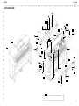
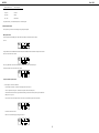
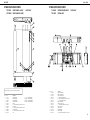
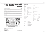
A EXPLODED VIEW
B
C
D
E
F
G
H
I
J
K
L
M
N
O
P
Q
R
S
T
U
V
Nov. 1998
NOTE
The cushion under the UPPER BLIND H is #01452501 UPPER BLIND CUSHION.
3
HP-555G
Nov. 1998
PARTS LIST
PARTS LIST OF EXPLODED
No.
q
w
e
r
t
y
u
i
o
!0
!1
!2
!3
!4
!5
!6
!7
!8
!9
@0
@11
@2
@3
@4
@5
@6
@7
@8
@9
#0
#1
#2
#3
#4
#5
#6
Pno.
01346167
00900478
01346190
22325182
01234656
01452490
00239367
01346256
01346234
71011878
00900534
01455767
O1344467
71011867
13129139
22495576
71012234
01346178
71015512
01017134
01450212
71121767
71012690
01341956
01013089
71012223
01455778
71011901
01349778
00904145
00904090
00900467
01346245
01454590
00900289
00900567
Part Name
TOP BOARD
TOP BOARD HOLDER
MUSIC REST
MR HINGE ASSY
HINGE CUSHION A
MUSIC STOPPER
SHOULDER SCREW 1165
UPPER HOLDER
UPPER BLIND
PAB3 INLET 100/117V
BRACKET
END BLOCK L
SW HOLDER
PAB3 FRONT JACK BRD
AC PUSH SWITCH
A S-BUTTON LX BLK
SIDE PANEL L ASSY
LID BOARD
LID BLIND ASSY
LID RAIL STOPPER
PWR TRANS 01450212 UNIVERSAL
PAB3 ANALOG PHANTOM
MAIN BOARD ASSY
FDD MF355F-3252MG
DD HOLDER
SIDE PANEL R ASSY
END BLOCK R
MIC BOARD ASSY
FULL-RANGE PD-20103A3
TW HOLDER
TWEETER TW-5104A
PWB HOLDER
LOWER BLIND
FRONT PANEL
CENTER HOLDER
PANEL HOLDER FP
No.
A
B
C
D
E
F
G
H
I
Pno.
40011123
40011312
40012178
40012145
40012490
40011323
40011056
40128512
40011101
Part Name
BINDING TAPTITE B 4*8 BZC
BINDING TAPTITE P 3*8 BZC
TPA BIND 3 x 12 BZC
TPA TRUSS 4 x 14 BZC
PAN TAPTITE P 4 x 10 BZC
PAN TAPTITE P 3 x 10 BZC
BINDING TAPTITE B 3 x 6 ZC
BINDING TAPTITE B WH 4 x 25 x 20 BZC W=11
BINDING TAPTITE B 3 x 8 BZC
SAFETY PRECAUTION:
The parts marked have safetyrelated characteristics.
Use only listed parts for
replacement.
CONSIDERATIONS ON PARTS ORDERING
When ordering any parts listed in the parts list, please specify the following items in the order sheet.
QTY
PART NUMBER
DESCRIPTION
MODEL NUMBER
10
22575241
Sharp key
C-20/50
Ex.
15
2247017300
Knob (orange)
DAC-15D
Failure to completely fill the above items with correct number and description will result in delayed or even
undelivered replacement.
NOTE : The parts marked # are new (initial parts).
CASING
01346167
01346190
22325182
01452490
01346178
71015512
01346334
01346189
01346234
01346245
01346223
01454590
32225353
00341778
01346201
00890990
01455767
01455778
01346323
01452501
00121945
01011923
71012267
TOP BOARD
MUSIC REST
MR HINGE ASSY
MUSIC STOPPER
LID BOARD
LID BLIND ASSY
LID BLIND CUSHION
LID BLIND
UPPER BLIND
LOWER BLIND
REAR PANEL
FRONT PANEL
I S-ESCT SX1V BLK L=30
KEY FELT
DISPLAY COVER
ROLAND BADGE 12 GOLD
END BLOCK L
END BLOCK R
LID CUSHION
UPPER BLIND CUSHION
SPEAKER COVER
ESCUTCHEON FDD
BOTTOM BOARD
NOTE : BOTTOM BOARD ASSY includes the following parts.
00569156
01011534
71012223
CUSHION T1 x 25 x 1200
CUSHION
SIDE PANEL R ASSY
NOTE : SIDE PANEL R ASSY includes the following parts.
********
00900534
00900512
00900523
71012234
SIDE PANEL R
BRACKET
PANEL HOLDER R
SIDE PLATE R
SIDE PANEL L ASSY
NOTE : SIDE PANEL L ASSY includes the following parts.
********
00900534
00900490
00900501
CHASSIS
00900390
01017134
00900356
22175664
00900478
00900289
00900490
00900512
4
LID SHAFT
LID RAIL STOPPER
LID ANGLE
LID GEAR
TOP BOARD HOLDER
CENTER HOLDER
PANEL HOLDER L
PANEL HOLDER R
SIDE PANEL L
BRACKET
PANEL HOLDER L
SIDE PLATE L
MB
PLB
PRB
IB
EB
PAB
LAB
LBB
MIC
FJB
:
:
:
:
:
:
:
:
:
:
MAIN BOARD
PANEL L BOARD
PANEL R BOARD
INLET BOARD
EQ BOARD
PAB ANALOG BOARD
LCD A BOARD
LCD B BOARD
MIC BOARD
FRONT JACK BOARD
HP-555G
00900467
22245194
22145199
22145901
01234656
01011390
00900567
01346267
00904145
01344467
01346256
01453267
00569156
01011534
01013089
22265242
22165134
01454301
12339355
01346390
Nov. 1998
NOTE1: PANEL L BOARD ASSY includes the following parts.
PWB HOLDER
POT DUST COVER M 1H
SHAFT STAY L
SHAFT STAY R
HINGE CUSHION A
SHAFT CUSHION
PANEL HOLDER FP
BLIND ANGLE
TW-HOLDER
SW HOLDER
UPPER HOLDER
DISPLAY HOLDER
CUSHION T1 x 25 x 1200
CUSHION
DD HOLDER
DD INSULATER
COLLAR
LED SPACER LH-36-5
SWITCH COVER 721128-18
ISOLATOR LED SPONGE
01450034
01450045
01450023
71012723
D
D
D
D
D
D
D
D
D
D
A
I
S-KEYTOP
S-KEYTOP
S-KEYTOP
S-KEYTOP
S-KEYTOP
S-KEYTOP
S-KEYTOP
S-KEYTOP
S-KEYTOP
S-KEYTOP
S-BUTTON
S-KNOB S
PANEL R BOARD ASSY
NOTE1: PANEL R BOARD ASSY includes the following parts.
01452712
01452734
01452723
71011878
WIRING 10X100-P2.0-51065-51015-F
WIRING 14X350-P2.0-51065-51015-F
WIRING 15X400-P2.0-51065-51015-F
PAB3 INLET 100/117V
NOTE1: PAB3 INLET 100/117V includes the following parts.
23425740
12559444
00129367
INL-8 10A/125V 2P PO
5x20 SB 4 4A/125V
INLET HOLDER
AC INLET
FUSE
NOTE2: Replacemant IB PAB3 INLET ASSY is for 100/117V version exclusive use.
When using PAB3 INLET ASSY for 230/240V version, be sure to make the following modifications.
1. IB FOR 100/117V version differs from 230V version in FUSE system.
Replace fuse(F1 on IB) to specific one.(#12559550 FUSE 5x20 S506 1.6A T1.6AL250V for 230V version) See
TABLE A.
2. For safety standards, place fuse seal (#40013712 FUSE SEAL T1.6AL250V #407) at the proper place of the
IB. The location of fuse seal is over the following printing (see fig A) of the PWB. When necessary, please order
fuse seal separatery from IB.
KNOB,BUTTON
22495312
22495340
00900145
01013023
00900156
00900167
00900178
00900189
01125901
00900190
22495576
22485192
WIRING 12X400-P2.0-51065-51015-F
WIRING 8X400-P2.0-51065-51015-F
WIRING 9X350-P2.0-51065-51015-F
MD1H MCG
MX1H DWG
SD1H BLK
SD1H DRD
SD2H BLK
SD3H BLK
SD4H BLK
SX1H BLK
SX1H-A BLK
SX2H BLK
LX BLK
BLK/LCG
SWITCH
13169752
01340290
13169626
13129139
13159363
EVQ 213 05R
EVQ11A
SKHJAB 005A
SDDLB1-A-D-2 TV-5 5A/250V
SSSF124-S09N-1
TACT SWITCH
TACT SWITCH
TACT SWITCH
AC PUSH SWITCH
SLIDE SWITCH
SW1,4-13,15-17 on PLB, SW1-18 on PRB
SW2,3,4,8 on LBB
SW1,5,7 on LBB
SW301 on FJB
TABLE A
100V/117V
230V/240V
JACK, SOCKET
13449283
23425740
13429911
13449252
00340223
13429672
13429676
HLJ7101-01-3010
INL-8 10A/125V 2P PO
TCS7927-28-401
YKB21-5006
YKF51-5031
YKF51-5047
YKF51-5048
LACK 6.5MM PHONE
AC INLET
DIN
STEREO PHONE
DIN
DIN
DIN
JK1-4 on PAB
JK401 on PAB3 IB
JK304 on FJB
JK301,302 on FJB, JK1on MIC
JK5 on PAB
JK303 on FJB
JK6 on PAB
Fig.A
3.15A/125V
71121767
PAB3 ANALOG PHANTOM
NOTE : PAB3 ANALOG PHANTOM includes the following PWBs.
LCD UNIT
71013990
FUSE 5 x 20 SB 4 4A/125V
FUSE 5 x 20 S506 1.6A T1.6AL250V
********
********
LCD UNIT
PAB3 EQ BOARD ASSY
PAB3 ANALOG BOARD
NOTE : PAB3 ANALOG BOARD includes the following parts.
FLOPPY DISK DRIVE
01341956
22195975
22195973
01349990
01349978
01349912
01346423
01346412
12199584
FDD MF355F-3252MG
SPEAKER
01349778
00904090
FULL-RANGE PD-20103A3
TWEETER TW-5104A
KEYBOARD ASSY
71017401
PA-4A88-C2 KEYBOARD ASSY
NOTE : For details, please refer to KEYBOARD PARTS LIST. (Page. 22)
71011901
TR HOLDER
POWER AMP HOLDER
WIRING W4
7X250-P2.0-PH-SAN-F
12X130-P2.0-PH-SAN-F
HEATSINK
PAB HOLDER
GROUNDING TERMINAL M1698
WIRING
WIRING
WIRING
CN501 on PAB
CN7 on PAB
CN16 on PAB
MIC BOARD ASSY
NOTE : MIC BOARD ASSY includes the following parts.
PCB ASSY
E 71012690
71012712
MAIN BOARD ASSY
PANEL L BOARD ASSY
22150756
01344489
JACK NUT 2
MIC HOLDER
5
HP-555G
71011867
Nov. 1998
PAB3 FRONT JACK BRD
15019444
MTZJ T-77 9.1B
15039159T0 S5688G(TPA3)
NOTE : PAB3 FRONT JACK BOARD includes the following parts.
01344545
71012167
D17,20,21 on PAB
D3,4,9,10,11,13,14,19 on PAB
OPTICAL DEVICE
JACK HOLDER
LCD B BOARD ASSY
NOTE : LCD B BOARD ASSY includes the following parts.
01454301
01453267
ZENER
RECTIFIER
LED SPACER LH-36-5
DISPLAY HOLDER
01346489
01345445
15039245
LED LNJ308G8LRA
L-1384AD/1ID
LED SEL6210S TP5
LED
LED(ANGLE)
LED
01121689
LED SPR-325MVWT31
LED
LED1-72 on LAB
D301 on FJB
on LBB, LED1,4-13,15,17 on PLB,
7-10,12-14 on PRB
LED2 on LBB, LED17 on PLB
MCR50 JZH J 8R2
ERDS1VJ331T
RCE9A103JAG7A
EXBV8V101JV
EXBV8V103JV
EXBV8V470JV
EXBV8VR000V
METAL FILM
CARBON
ARRAY
ARRAY
ARRAY
ARRAY
ARRAY
R7 on LAB
R1,2 on PAB
RA1,4,6-12,28 on MB
RA2,3,5,19,30-32,38-40 on MB
RA13-18,20-23,34,35,41 on MB
RA24,25,26,27 on MB
RA29 on MB
12M/M EVJ05HEB1B14 with NUT
30M/M RS30111CA
30M/M. EWANNKX10B14(10KBX2)
ROTARY
SLIDE
SLIDE
VR1,2 on MIC
VR3 on PLB
VR1,2 on PLB
01453278
15369152
15369154
DE1307E 472M-KH
ECEV1CA100SR
ECEV1CA330WR
CERAMIC
CHEMICAL
CHEMICAL
15359780
01015889
15359774
15369109
01340389
01452189
13639144M0
15369154
ECHU1H152JB5
ECHU1H471JB5
ECHU1H681JB5
ECEV0JA101SP
ECOS1VP682BB
ECKDBE472ZF
ECA1CM682
ECEV1CA330WR
POLYEST
POLYEST
POLYEST
CHEMICAL
BLOCK
CERAMIC
CHEMICAL
CHEMICAL
C401 on IB
C135,136,162 on MB
C12,13,29,30,90-93,96,99,100,102,138,190,191,
194-196,198 on MB
C176,C177 on MB
C178,C179,C192,C193 on MB
C174,175 on MB
C85 on MB
C39,51 on PAB
C5,44 on PAB
C22 on PAB
C8 on LAB
N2012Z102T01
EXC ELDR25V
RUBBER CONNECTOR
FERRITE-BEAD
FERRITE-BEAD
L1-21 on MB
L301-311 on FJB
CRYSTAL
CRYSTAL
CRYSTAL
X1 on MB
X3 on MB
X2 on MB
RELAY
RL1 on PAB
5X20 S506 1.6A T1.6AL250V
5X20 SB 4 4A/125V
5X20 SB 5 5A/125V
CNT47-0003A
FUSE
FUSE
FUSE
HOLDER
F1 on PAB3 IB(230V/240V ASSY)
F1 on PAB3 IB(100V/117V ASSY), F5 on PAB
F3,4 on PAB
F1 on PAB3 IB, F3,4,5 on PAB
10JQ-ST
53253-0510
53253-0610
53253-0810
53253-0910
53253-1010
53253-1210
53253-1410
53253-1510
53313-1415
B10B-XH-A
CONNECTOR
CONNECTOR
CONNECTOR
CONNECTOR
CONNECTOR
CONNECTOR
CONNECTOR
CONNECTOR
CONNECTOR
CONNECTOR
CONNECTOR
CN201 on EB
CN2 on PLB, ’CN8 on MB
CN1 on MIC, CN11 on PAB
CN13 on PAB
CN7 on MB
CN1on LBB
CN6 on MB
CN6 on PLB
CN5 on PLB
CN5 on MB, CN1 on LAB
CN15 on PAB
LED1-5,
RESISTOR
IC
01344278
00129278
00343823
00897078
01341167
01453689
01344245
01126612
15199904
15199923
15199780
00232567
00780645
00899756
01126778
01238012
01340467
15289105
15189184
15189189
15189250
15199221
00236067
15289402
15199231
01344512
15169515
15259884
15259885
00127490
00232645
15169550T0
15169556T0
01349590
15169304H0
15229706S0
HD6437034AD72F
SSC1080F0B
M60205-0601FP
RA01-005 (TC170C200AF-005)
LH28F400SUT-NF60
LH5S86NO DEMO
LHMNOPYL WAVE
TC514260DJS-60(YEL)
IC M51953BL-600Y
SED1278F0A
HD63266F
PCM69AU-1/T2
IC M5M34051P RS422 TRANSCEIVER
NJU6417CFC1
24LC01BT-I/SN
DIGITAL ECHO IC M65850P
STK401-040
UPC4570G2
NE5532
UPC4570HA
M5218AL
AN78M12F
AN79M12F
REGULATOR TA78L05F(TE12L)
UPC78L05J-T
UPC24A05HF
TC74HC00AP
TC7S08F (TE85L)
TC7S32F(TE85L)
TC7W08F(TE12L)
TC7W14F(TE12L)
TC74HC138AP
TC74HC574AP
TC7WU04FU(TE12L)
HD74LS04P
PC910X
CPU
CUSTOM IC
CUSTOM IC
CUSTOM IC
FLASH MEMORY
MASK ROM
MASK ROM
DRAM
RESET IC
LCD DRIVER
FDC
DAC
TRANSCEIVER
LCD-DRIVER
EEPROM
ECHO IC M65850P
POWER AMP
BIPOLAR OP-AMP
BIPOLAR OP-AMP
BIPOLAR OP-AMP
BIPOLAR OP-AMP
REGULATOR(+12V)
REGULATOR(-12V)
REGULATOR(+5V)
REGULATOR(+5V)
REGULATOR(+5V)
CMOS
CMOS
CMOS
CMOS
CMOS
CMOS
CMOS
CMOS
TTL
PHOTO COUPLER
IC3 on MB
IC1 on MB
IC8 on MB
IC13 on MB
IC38 on MB
IC15 on MB
IC18 on MB
IC22,23 on MB
IC9 on PLB, ’IC13 on PAB
IC2 on LAB
IC2 on MB
IC5 on MB
IC303 on FJB
IC1 on LAB
IC32 on MB
IC2 on MIC
IC12 on PAB
IC4,12 on MB
IC201,202 on EB
IC3,4 on MIC, IC6,7,8,9 on PAB
IC1,4 on PAB, ’IC5,7,8 on PLB
IC5 on PAB
IC3 on PAB
IC6 on MB
IC1 on MIC
IC2 on PAB
IC301 on FJB
IC33 on MB
IC11,26 on MB
IC19 on MB
IC35 on MB
IC3,4 on PLB
IC1 on PLB
IC7 on MB
IC11 on PAB
IC302 on FJB, IC10 on PAB
00898201
15119132
15119615
15129151
15129152
15129623
15139124
15129168
15119163
RN2421(TE85L)
2SA1015-GR(TPE2)
2SB647CTZ
2SC1815-GR(TPE2)
2SC2878-A(TPE2)
2SD667CTZ
2SK363-GR(TPE2)
DTC124ESATP
RN2227(TPE4)
DIGITAL TR
BIPOLAR
BIPOLAR
BIPOLAR
BIPOLAR
BIPOLAR
J FET
DIGITAL TR
DIGITAL TR
Q1 on MB
Q3,4 ,10,15 on PAB
Q17 on PAB
Q2,5,13,18,19 on PAB
Q1,8 on PAB
Q16 on PAB
Q6,7,11,12 PAB
Q21,22 PAB
Q301 on FJB, Q1,2,3 on PLB, Q1,2,3,4 on PRB,
Q14,20,23 PAB
00456856
TD 62593AP TR ARRAY
IC2 on PLB
01121323
15039176
15019126
DA204U T106ARRAY
D3SBA20 4A/200V
1SS133 T-77
DA1,2,3,4,8 on MB
BRIDGE
SWITCHING
15019685
MTZJ T-77 27C
ZENER
00120778
01014278
15399965
00126112
15409113
01013578
01011845
POTENTIOMETER
01348189
00346178
00671556
CAPACITOR
FILTER
01455623
12449380
01346389
CRYSTAL
00894034
00894023
00901912
MA-406 16.000MHZ
MA-406 20.000MHZ
MA-406 24.576MHZ
TE24
TE24
TE24
RELAY
TRANSISTOR
00899245
G5Z-2A DC12V/5A
FUSE,FUSE HOLDER
12559550
12559444
12559445
12189823
CONNECTOR
DIODE
D1,D15 on PAB
D302 on FJB , D1-4 on MIC, D1-2,D4-8 LBB, D1,
4-13,15-17,20,21 on PLB, ’D1-18 on PRB,
D5-8,12,18,22-24 on PAB
D303,304,305,306,307,308 on FJB
6
01344578
13369927
13369928
13369930
13369931
13369932
13369934
13369936
13369937
01451556
01344567
HP-555G
13369564
13369898
13369585
13369567
13369981
13369503
13369504
13369890
13369516
13379151
13379152
12199584
01347923
13369877
Nov. 1998
B12B-PH-K-S JST
B2P3-VH 7A/250V
B3P5-VH 7A/250V
B4B-PH-K-S JST
B5P-VH 7A/250V
B7B-PH-K-S JST
B8B-PH-K-S JST
B8P-VH 7A/250V
B9B-PH-K-S JST
FFC IL-FPC-14ST-N
FFC IL-FPC-16ST-N
M1698
MEP1866-A
PS-34PE-D4T1-B1-K
CONNECTOR
CONNECTOR
CONNECTOR
CONNECTOR
CONNECTOR
CONNECTOR
CONNECTOR
CONNECTOR
CONNECTOR
CONNECTOR
CONNECTOR
GROUND TERMINAL
GROUND TERMINAL
CONNECTOR
CN11 on MB
CN402 on IB
CN401 on IB
CN4 on PAB
CN2 on PAB
CN10 on MB
CN301 on FJB, CN1 on PAB
CN9 on PAB
CN302 on FJB, CN9 on MB
CN4 on MB
CN3 on MB
TER3,4 on PAB
TER1,2 on PAB
CN1 on MB
ACCESSORIES
71121034
71012667
13499219
13499220
13499221
13499222
00905234
40239434
40239445
17048910
40340056
OWNER’S MANUAL ENGLISH
OWNER’S MANUAL JAPANESE
AC CORD SET 100V
AC CORD SET 120V
AC CORD SET 230V
AC CORD SET 240VA
EURO CONVERTER PLUG ECP01-5A
PIANIST TEMPLATE JAPANESE
PIANIST TEMPLATE ENGLISH
FLOPPY DISK DEMO JAPANESE
LEAFLET DEMO SONG LIST
DC-382-J01
UC-713-J01
EC-511-E07
SC-078-J02
VFF2P
SJT2P18AWG60
H03VVH2-F 2P
ES206-75HMA
230V VERSION ONLY
100V VERSION ONLY
100V VERSION ONLY
WIRING
01454567
01450089
01450090
01452756
01454589
01454578
01452745
01450056
01450078
01450067
01346090
WIRING 5X600-P2.0-51065-51065-F
WIRING W3
WIRING W2
WIRING W1
WIRING FDD 34P FLAT
WIRING FDD POWER
WIRING 14X250-P2.0-51089-51089-F
WIRING 6X1050-P2.0-51065-51065-F
WIRING 8X800-P2.0-PH-PH-F
WIRING 9X1050-P2.0-PH-PH-F-S
LCD HOUSING
TRANSFORMER
01450212
POWER TRANSFORMER
01450212 UNIVERSAL
SCREW
22285342
CONNECTING PIN
40011056
BINDING TAPTITE B 3 x 6 ZC
40011101
BINDING TAPTITE B 3 x 8 BZC
40011112
BINDING TAPTITE B 3 x 10 BZC
40011123
BINDING TAPTITE B 4 x 8 BZC
40011256
PAN TAPTITE P 2 x 6 ZC
40011312
PAN TAPTITE P 3 x 8 BZC
40011323
PAN TAPTITE P 3 x 10 BZC
40011490
PAN MACHINE SCREW W/SW M3 x 6 BZC
40011712
WOOD ANCHOR NUT B M4 x 11.5 ZC
40011723
WOOD ANCHOR NUT B M5 x 12 ZC
40011956
PLAIN WASHER 3 x 10 x 0.8 ZC
40012034
TRUSS MACHINE SCREW M4 x 18 BZC
40012090
TRUSS TAPPING A 4 x 12 ZC
40012145
TRUSS TAPPING A 4 x 14 BZC
40012178
BINDING TAPPING A 3 x 12 BZC
40012490
PAN TAPTITE P 4 x 10 BZC
40012634
WOOD ANCHOR NUT B M8 x 13.5 ZC
40012867
PAN MACHINE SCREW W/SW+PW M3 x 8 ZC
40012890
PAN MACHINE SCREW W/SW+PW M3 x 16 ZC
40012901
PAN MACHINE SCREW W/SW+PW M3 x 20 ZC
40012923
PAN MACHINE SCREW W/SW+PW M4 x 25 ZC
40013056
PAN MACHINE SCREW W/SW+PW M3 x 6 ZC
40121923
PAN MACHINE SCREW W/SW+PW M4 x 18 ZC
40128512
BINDING TAPTITE B WH 4 x 25 x 20 BZC W=11
40231090
PAN TAPPING A 6 x 12 ZC
40239378
BINDING TAPPING A 3.5 x 6 ZC
40239401
BINDING TAPPING A 3.5 x 8 BZC
00239367
SHOULDER SCREW 1165
00568756
PA-4A STOP SCREW
PACKING
01560212
01560189
01560190
01346345
01346356
PACKING CASE
PAD CARTON LOWER
PAD CARTON UPPER
PAD L
PAD R
7
HP-555G
Nov. 1998
CHECKING THE VERSION
NUMBER
HOW TO UPDATE THE FLASH
MEMORY
Press the [Function] button to enter Function mode.
Then while holding down the [PLAY] and [TRACK[4]] buttons,
HP-555G uses Flash Memory for the main program registration,
press the [Function] button.
you can make the software update by floppy disks via internal FDD.
Please refer to the following "Update Procedure."
The system program version number will be displayed.
Required Item
After this checking, HP-555G will enter TEST MODE.
If you wish to exit TEST MODE, turn off the power.
HP-555G Ver. Up Disk (P/No.17048901)
Update Procedure
1: Insert the MT-300S Ver. Up Disk into the disk drive.
2: Turn the power ON while holding [Tempo] and
[Metronome] buttons.
3: All of the LEDs on the panel blink as follows.
Normal : Blinks slowly
Error
: Repeat quick double brink
4: When it is in normal condition, LCD may show *Flash
ROM Update* for a moment and loading the program
will be started. During the update, LCD will display
****** ##/08.*
The ******* and *##* part shows the working condition.
Refer to the following.
***** : Reading (now loading the program)
: Writing (now writing the program)
##
: counts from 01 to 08
5: When the update procedure is normal ended, *finished*
will be displayed to the LCD. Turn ON the power again
and confirm the System Version number and execute
Test Mode.
If *finished* has not been displayed to the LCD display,
turn OFF and ON the power again and retry the update
procedure from the first. If the result is the same, contact
Roland Service Center.
8
HP-555G
Nov. 1998
TEST MODE
Note!: When you enter item 9), the user setting data will be set to the factory settings.
Required Items
• MIDI Cable (1.5m or longer Part No.23485229 1.5m)
• Computer Test Cable for Sound Canbas SC-88 (P/No. 17049906)
• Michrophone
• Osciloscope
1. Entering test mode
After turning on the power, press the [Function] button two times while holding down the [Track 4] and [Play] button to enter the Test
Mode.
The following display will appear, and you will enter test mode.
V*** : version number
B*** : build number (This is for factory use only)
*** : destination region (DOM: 100V specs, EXP: 117/230/240V specs)
C*** : CPU build number (This is for factory use only)
* (Build number) and (CPU build number) are generally not displayed in the LCD, but some units of the initial production may display
these. As this numbers are displayed for factory purpose, please ignore when you execute Test mode during the repair.
Press the [Function] button to move to item 2.
* To advance to the next item you will generally use the [Function] button.
For some items, you will advance automatically, so refer to the explanation of each item.
* If you wish to exit test mode during this procedure, turn off the power.
2. Device check and display of ROM version, etc.
During the device check, the following display will appear.
9
HP-555G
Nov. 1998
If a problem is found, the following error display will appear.
DEVICE
(Error content)
Err PROGRAM ROM
Program (Flush or mask ROM) fault
Err DRAM
Work DRAM read/write fault
Err Wave ROM
Wave ROM data content fault
Err RAM for DSP
DSP RAM read/write fault
Err EEPROM
EEPROM read/write fault
Err DATA ROM
DATA ROM data content fault
Err DATA TYPE
DATA ROM type check fault
Err FDC EX PORT
FDC EXISENCE PORT fault
If an error display appears, press the [Function] button to advance the test mode.
If the test results were OK, the following display will appear.
Press the [Function] button to advance to item 3.
3. Button and LED check
All LEDs will light, and the following display will appear.
Note!: If you wish to check item 3, do not press the [Function] button first.
If you press the [Function] button first, you will advance to item 4.
Once you begin the checking process for this test item, it is not possible to advance to the next item before testing all buttons.
Press the following buttons, and confirm that a sound is heard and that the button LED goes dark.
[piano] [E.piano] [Harpsi] [Vibes] [Organ] [Strings] [Choir] [GS Tones] [Reverb] [Chorus] [Pianist] [Split]
[Transpose] [Composer Rhythm] [Composer 1] [Composer 2] [composer 3] [composer 4] [Play] [Rec] [MEMU]
[Count in] [Marker A] [Marker B] [repeat] [Function]
Press the following button twice, and confirm that a sound is heard and that the button LED changes from orange to green to dark.
[Key Touch]
10
HP-555G
Nov. 1998
Press the following button twice, and confirm that a sound is heard and that the button LED on the left side of the display changes from
orange to green to dark, and that the button LED goes dark the second time.
[Metronome]
* Press the following buttons, and confirm that a sound is heard and that the characters shown in the LCD ("S" for [Song], "B" for [Beat],
"T" for [Tempo], "+" for [Value+], "-" for [Value-], "D" for [Disk], "R" for [Reset], "S" for [Stop], "B" for [Bwd], "F" for [Fwd] and "C"
for [Clear]) disappear.
[Song] [Beat] [Tempo] [Value+] [Value-] [Disk] [Reset] [Stop] [Bwd] [Fwd] [Clear]
If all buttons are normal, you will automatically advance to item 4.
4. Checking the effect sound and speaker panning etc.
The following display will appear.
Press the following buttons to check the effect sound and the panning etc.
BUTTON
PANNING
TONE
EFFECT
INDICATION of LCD
[piano]
CENTER
PIANO
none
DRY
[E. piano]
CENTER
PIANO
CHORUS
CHORUS
[Harpsi]
CENTER
PIANO
REVERB
REVERB
[Vibes]
CENTER
PIANO
RESONANCE
RESONANCE
[Organ]
LEFT
440Hz sine wave
none
PAN L
[Strings]
RIGHT
440Hz square wave
none
PAN R
[Choir]
CENTER
440Hz sine wave
none
PAN LR
If you press the [Function] button you will advance to item 5.
5. Pedal and Balance slider operation check
The following display will appear.
At this time, you can move to item 6 by pressing [Function].
Slowly depress each of the three pedals ([Soft Pedal], [Sostenuto], [Damper]) one at a time, and confirm that the value in the LCD changes
from 0--9, and that the metronome sound is heard when the display reaches "9." Then move the Balance Slider from left end to the right end,
and confirm that the sound is heard and that the pitch changes related to the slider. The value in the LCD changes from 0--9, and that the
metronome sound is heard when move the slider from left end to the right end.
11
HP-555G
Nov. 1998
INDICATION of LCD
Names of the pedals
SS*(value)
Soft Pedal
SF*(value)
Sostenute
DP*(value)
Damper
BL (value)
Balance Slider
If no problem is found, you will automatically advance to the following item.
6. Serial interface check
When you want to go to the next test item during this check, press [Function] button.
MIDI operation check
Set the computer switch to the MIDI position. "s" symbol will be displayed to the middle of "FM" and "RM" in
the LCD.
Using a MIDI cable, connect the MIDI IN located under the keyboard to the MIDI OUT located at the back of the piano. If the test result is
OK, the LCD will indicate "OK" as follows.
Then, using a MIDI cable, connect between the MIDI IN and the MIDI OUT located at the back of the piano.
If the test result is OK, the LCD will indicate "OK" as follows.
*Computer interface operation check
(1) Mac: Settings for connection to a Macintosh.
Set the computer switch to Mac. An underline will be displayed below Mc in the LCD.
Connect a computer test cable (part no. 17049906) to the Computer connector under the keyboard.
Check both ends of the white conductor (signal) and black conductor (ground) of the test cable by oscilloscope, and confirm that a 1
MHz square wave is present.
Now turn on the switch of the computer test cable. If the result is normal, the OK will appear in the LCD as follows.
Turn off the switch of the test cable.
If the result is OK, the following display will appear in the LCD.
12
HP-555G
Nov. 1998
(2) PC1: Settings for connection to a PC-9800.
Set the computer switch to PC1. An underline will be displayed below P1 in the LCD.
Connect a computer test cable (part no. 17049906) to the Computer connector under the keyboard, and turn on the switch of the
computer test cable. If the result is OK, the following display will appear.
Turn off the switch of the test cable.
If the result is OK, the following display will appear in the LCD.
(3)PC2: Settings for connection to an IBM-compatible computer
Set the computer switch to PC2. An underline will be displayed below P2 in the LCD.
Connect a computer test cable (part no. 17049906) to the Computer connector under the keyboard, and turn on the switch of the
computer test cable. If the result is OK, the following display will appear.
Turn off the switch of the test cable.
If the result is OK, the following display will appear in the LCD.
Press the [Function] button to proceed to item 7.
7. Floppy Disk Drive check
When floppy disk has not inserted, "NO DISK" will appear in the LCD.
Insert formatted 2DD disk to the drive.
When there is no problem, "2DD: OK" will appear in the LCD.
(If there is a problem, "2DD: NG" will appear in the LCD.)
Then insert 1.44Mb formatted 2HD disk to the drive.
When there is no problem, "2HD: OK" will appear in the LCD.
(If there is a problem, "2HD: NG" will appear in the LCD.)
Press the [Function] button to proceed to item 8.
13
HP-555G
Nov. 1998
8. LCD check
When you enter this mode, the entire LCD will go dark.
Next, press the [Function] button and confirm that the LCD lights entirely as following.
Press the [Function] button again. Confirm the following display will appear in the LCD.
Press the [Function] button to proceed to item 9.
9. Destination region setting
The following display will appear.
Now press the [Beat] button to select DOM (100V) specifications, or press the [Tempo] button to select EXP (117/230/240V)
specifications.
* When you enter this setting, the HP-555G will automatically return to the factory settings.
Press [Function] button to proceed to the next test.
10. Exiting test mode
To exit test mode, turn off the power.
(If press the [Function] button here, you can jump to the first item of the Test Mode.)
11. Mic check
After exiting test mode, connect a mic to the Mic In jack located under the keyboard, and rotate the knobs (Mic Volume and Mic Echo) to
verify that each function operates correctly.
14
HP-555G
Nov. 1998
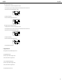
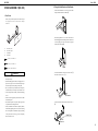
STAND ASSEMBLY (KS-505)
2. Fixing the Pedal Board and Side Boards
¡ Position the Pedal Board so it rests on top of the metal
fitting at the bottom of the Side Board q.
1. Part Check
Before you begin assembling the stand, check that all the parts
were supplied. You will also need to have a Phillips
screwdriver.
A
C
D
B
A:
Side Board ( left )
B:
C:
Side Board ( right )
Pedal Board
D:
Rear Board
¡ Move the Pedal Board so it is in close contact with the
Side Board w, then while shifting it forward or backward
as necessary e, push it down until it has been grasped
firmly by the metal fitting r.
Screw a ( 4 x 20 mm ) x 8
Screw b ( 4 x 25 mm ) x 4
Screw c ( M5 x 20 mm ) x 2
CAUTION
•
•
•
•
•
•
•
Make sure that another person is on hand to help with the
assembly and setup.
When assembling the piano stand, do not apply excessive
pressure on any part. To do so can cause metal parts to get
bent out of shape, and may damage wooden parts.
Be very careful, when you assemble and move the piano,
to make sure that you do not drop it on your hands or feet.
To move the piano, lift it carefully—all the while keeping
it level.
Fasten each screw tightly, then place the stand in a stable
and horizontal place.
Do not allow the pedal cord or power cable to get twisted
or pinched while assembling the stand.
At first, assemble the entire stand in a temporary fashion,
without really tightening the screws. Then, after checking
the overall alignment of the boards (and gently shifting
certain parts where necessary), go around and tightly
fasten each of the screws.
¡ Push the Pedal Board in the direction of the arrow t,
then fasten it with screws “a” y.
Screw a
¡ In the same manner, fasten the other side with screws “a”
u.
Pedal Cord
Screw a
15
HP-555G
Nov. 1998
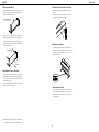
3. Fitting the Rear Board
5. Connecting the Pedal and Power Cords
¡ Position the Rear Board so the side on which the woodgrain is visible faces the same direction as the three
pedals, as shown in the illustration.
¡ Connect the pedal cord to the Pedal jack on the rear of the
piano.
¡ Connect the power cord to the power inlet on the piano,
then plug the other end into a wall socket.
Wood grain side
¡ Using screws “a,” fasten the Rear Board to the Side
Boards at right and left (two screws each at right and left).
Then, fasten the Rear Board to the Pedal Board with
screws “b” (four places). Observe the direction shown by
the arrow in the illustration.
6. Adjusting the Adjuster
¡ Lower the adjuster at the bottom of the pedal board (by
rotating it), so that the pedal board touches the floor. If
you have the piano placed on a carpet, lower it until it
pushes into the carpet.
Screw a
Screw b
4. Installing the Piano on the Stand
¡ Align the joint screws (one each at right and left) on the
bottom of the piano with the openings in the metal fittings
on the side board, then slide the piano forward until the
screws are held in place.
¡ Fasten the piano to the stand with the screw “c” (M5 X 20
mm) (one each for the right and left).
When Moving the Piano
Disconnect the power cord and raise the stand’s adjuster.
Then lift the piano while keeping it level, and move it
with care, so that you do not drop it on your feet, or get
your hands caught.
* When handling the piano, firmly grasp it at the front and
back. Be careful, so you do not get your fingers pinched.
16
HP-555G
Nov. 1998
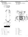
STAND EXPLODED VIEW
71019545
(71019556
SIDE BOARD L ASSY
SIDE BOARD R ASSY)
STAND EXPLODED VIEW
117/230/240V ONLY
The items bracketed by( )are parts for SIDE PANEL ASSY R
No.
q
w
e
r
t
y
u
i
Pno.
********
01451878
01451934
22205517
22125675
40010678
01452834
40010701
Part Name
SIDE BOARD L
(******** SIDE BOARD R)
SIDE HOLDER L
(01451889 SIDE HOLDER R)
REAR HOLDER L
(01451945 REAR HOLDER R)
JOINT HOLDER L
(22205518 JOINT HOLDER R)
ANGLE
4*20mm TRUSS HEAD TAPPING A1 Fe BZC
TOE BLOCK
4*35mm TRUSS HEAD TAPPING A1 Fe BZC
No.
q
w
e
r
t
y
u
i
o
!0
!1
!2
!3
!4
71120045
71019823
PEDAL BOARD ASSY
PEDAL UNIT
Pno.
71120045
22245308
71018623
40012923
40012123
40011556
40016545
40016512
40011323
40016578
22285396
01451878
01451889
40010634
Part Name
PEDAL BOARD ASSY
PEDAL BOARD FELT
PEDAL CENTER ASSY
4 × 25mm DOUBLE SEMS Fe ZC
4 × 25mm TRUSS HEAD TAPPING A1 Fe BZC
3.1 × 10mm ROUND WOOD ZC
SKM-1 TIE HOLDER
INSULOCK TIE T-18S
3 × 10mm BINDING HEAD P TITE Fe BZC
VINYL TIE 150mm
ADJUST BOLT
SIDE HOLDER L
SIDE HOLDER R
4 × 16mm TRUSS HEAD TAPPING A1 Fe BZC
117/230/240V ONLY
17
HP-555G
Nov. 1998
STAND PARTS LIST
#
Parts No.
Description
01451867
REAR BOARD
71019556
SIDE BOARD R ASSY
NOTE : SIDE BOARD R ASSY includes the following parts.
********
01452834
01451945
01451889
22125675
22205518
40010678
40010701
#
#
71019923
KS-505/KS-505D SCREW SET
NOTE : SCREW SET includes the following parts.
40010589
40010689
SIDE BOARD R
TOE BLOCK
REAR HOLDER R
SIDE HOLDER R
ANGLE
JOINT HOLDER R
4 × 20mm TRUSS HEAD TAPPING A1 Fe BZC
4 × 35mm TRUSS HEAD TAPPING A1 Fe BZC
40239278
71019545
SIDE BOARD L ASSY
NOTE : SIDE BOARD L ASSY includes the following parts.
********
01452834
01451934
01451878
22125675
22205517
40010678
40010701
#
SIDE BOARD L
TOE BLOCK
REAR HOLDER L
SIDE HOLDER L
ANGLE
JOINT HOLDER L
4 × 20mm TRUSS HEAD TAPPING A1 Fe BZC
4 × 35mm TRUSS HEAD TAPPING A1 Fe BZC
#
#
40010634
40012123
40011323
40012923
40011556
40016512
40016578
40016545
40239212
01452801
5 x 20mm TRASS HEAD
FeBZC × 2
4 x 25mm TRUSS HEAD TAPPING
A1 Fe BZC × 4
4 x 20mm PAN WASHER HEAD
TAPTITE C BZC × 8
4 × 16mm TRUSS HEAD TAPPING A1 Fe ZC
4 × 25mm TRUSS HEAD TAPPING A1 Fe ZC
3 × 10mm BINDING HEAD P TITE Fe BZC
4 × 25mm DOUBLE SEMS Fe ZC
3.1 × 10mm ROUND WOOD ZC
INSULOCK TIE 80M/M T-18S
VINYL TIE 150M/
SKM-1 TIE HOLDER
LEAFLET
PACKING CASE
71120045
PEDAL BOARD ASSY
NOTE : PEDAL BOARD ASSY includes the following parts.
22245308
40011701
PEDAL BOARD FELT
WOOD ANCHOR NUT M4 x 9.5 ZC
71019823
PEDAL UNIT
NOTE : PEDAL UNIT includes the following parts.
71018601
CONNECT CODE
NOTE : CONNECT CORD includes the following parts.
15229728
15119112
13299199
00907045
PHOTO INTERUPTER GP2S24B
TRANSISTOR 2SA1015-Y
TRIMMER EVND8AA03B13
PEDAL CABLE
71018623
PEDAL CENTER ASSY
NOTE : PEDAL CENTER ASSY includes the following
parts.
********
01451667
22285396
00907045
00904190
00908023
00904223
00908034
00677978
40011278
40011334
PEDAL CENTER
FELT
ADJUST BOLT
PEDAL CABLE
PEDAL CHASSIS
FELT L
COILED SPRING
6 x 35mm JOINT BOLT
6 x 12mm JOINT NUT
3 x 8mm BINDING HEAD P-TITE FeBC
3 x 12mm BINDING HEAD P-TIGHT Fe BZC
18
HP-555G
Nov. 1998
STAND EXPLODED VIEW
71018878
(71018889
SIDE PANEL L ASSY
SIDE PANEL R ASSY)
STAND EXPLODED VIEW
100V ONLY
The items bracketed by( )are parts for SIDE PANEL ASSY R
No.
q
w
e
r
t
y
u
i
o
!0
!1
Pno.
********
01451878
01451934
22205517
22125675
40010678
01451901
40010701
00900045
40019601
01451912
Part Name
SIDE BOARD L
(********
SIDE HOLDER L
(01451889
REAR HOLDER L
(01451945
JOINT HOLDER L
(22205518
ANGLE
4 × 20mm TRUSS HEAD TAPPING A1 Fe BZC
TOE BLOCK
4 × 35mm TRUSS HEAD TAPPING A1 Fe BZC
JOINT HOLDER
4 × 35mm FLAT HEAD TAPPING A1 Fe BZC
LEG
SIDE BOARD R)
SIDE HOLDER R)
REAR HOLDER R)
JOINT HOLDER R)
No.
q
w
e
r
t
y
u
i
o
!0
!1
!2
!3
!4
71120045
71019823
PEDAL BOARD ASSY
PEDAL UNIT
Pno.
71120045
22245308
71018623
40012923
40012123
40011556
40016545
40016512
40011323
40016578
22285396
01451878
01451889
40010634
Part Name
PEDAL BOARD ASSY
PEDAL BOARD FELT
PEDAL CENTER ASSY
4 × 25mm DOUBLE SEMS Fe ZC
4 × 25mm TRUSS HEAD TAPPING A1 Fe BZC
3.1 × 10mm ROUND WOOD ZC
SKM-1 TIE HOLDER
INSULOCK TIE T-18S
3 × 10mm BINDING HEAD P TITE Fe BZC
VINYL TIE 150mm
ADJUST BOLT
SIDE HOLDER L
SIDE HOLDER R
4 ×16mm TRUSS HEAD TAPPING A1 Fe BZC
100V ONLY
19
HP-555G
Nov. 1998
STAND PARTS LIST
#
Parts No.
Description
01451867
REAR BOARD
71018889
SIDE BOARD R ASSY
NOTE : SIDE BOARD R ASSY includes the following parts.
********
01451901
01451945
01451889
01451912
22125675
00900045
22205518
40010678
40010701
40019601
#
#
#
#
#
#
#
#
SIDE BOARD L
TOE BLOCK
REAR HOLDER L
SIDE HOLDER L
LEG
ANGLE
JOINT HOLDER
JOINT HOLDER L
4 × 20mm TRUSS HEAD TAPPING A1 Fe BZC
4 × 35mm TRUSS HEAD TAPPING A1 Fe BZC
4 × 35mm FLAT HEAD TAPPING A1 Fe BZC
71019923
KS-505/KS-505D SCREW SET
NOTE : SCREW SET includes the following parts.
40010589
40010689
SIDE BOARD R
TOE BLOCK
REAR HOLDER R
SIDE HOLDER R
LEG
ANGLE
JOINT HOLDER
JOINT HOLDER R
4 × 20mm TRUSS HEAD TAPPING A1 Fe BZC
4 × 35mm TRUSS HEAD TAPPING A1 Fe BZC
4 × 35mm FLAT HEAD TAPPING A1 Fe BZC
71018878
SIDE BOARD L ASSY
NOTE : SIDE BOARD L ASSY includes the following parts.
********
01451901
01451934
01451878
01451912
22125675
00900045
22205517
40010678
40010701
40019601
REPLACING FDD MF355F-3252MG (PNo.01341956)
#
#
40010634
40012123
40011323
40012923
40011556
40016512
40016578
40016545
40239023
01451856
00898189
01567034
40239278
5 × 20mm TRASS HEAD FeBZC ×2
4 × 25mm TRUSS HEAD TAPPING
A1 Fe BZC ×4
4 × 20mm PAN WASHER HEAD
TAPTITE C BZC × 8
When replacing MF355F-3252MG, attach 4 adhesive acetate fiber
tape (PNo.40122612) (10mm wide) to the new FDD before
mounting it on HP-555G (see the figure below).
Important : The tape is to isolate vibration and must be
4 × 16mm TRUSS HEAD TAPPING A1 Fe ZC
4 × 25mm TRUSS HEAD TAPPING A1 Fe ZC
3 × 10mm BINDING HEAD P TITE Fe BZC
4 × 25mm DOUBLE SEMS Fe ZC
3.1 × 10mm ROUND WOOD ZC
INSULOCK TIE 80M/M T-18S
VINYL TIE 150M/M
SKM-1 TIE HOLDER
LEAFLET
PACKING CASE
HEAD PHONE RH-30
STOOL(MAHOGANY)
attached.
NOTE1 : Wrap the tape once around the FDD, covering at least
1mm from the bezel's edge as shown in the figure.
Make sure that the tape cannot be seen from the front
when HP-555G is assembled.
NOTE2 : Attach the tape along the bottom
surface as shown in the figure.
Attach it to the other side as well.
Top
About 1—2mm
Adhesive acetate fiber tape
Bezel (Front Panel)
Screw Hole
NOTE3 : Wrap the tape once around and between
the screw holes on the bottom surface of
the FDD as shown in the figure.
71120045
PEDAL BOARD ASSY
NOTE : PEDAL BOARD ASSY includes the following parts.
22245308
40011701
PEDAL BOARD FELT
WOOD ANCHOR NUT M4*9.5 ZC
71019823
PEDAL UNIT
NOTE : PEDAL UNIT includes the following parts.
71018601
CONNECT CODE
NOTE : CONNECT CORD includes the following parts.
15229728
15119112
13299199
00907045
PHOTO INTERUPTER GP2S24B
TRANSISTOR 2SA1015-Y
TRIMMER EVND8AA03B13
PEDAL CABLE
71018623
PEDAL CENTER ASSY
NOTE : PEDAL CENTER ASSY includes the following
parts.
********
01451667
22285396
00907045
00904190
00908023
00904223
00908034
00677978
40011278
40011334
PEDAL CENTER
FELT
ADJUST BOLT
PEDAL CABLE
PEDAL CHASSIS
FELT L
COILED SPRING
6*35mm JOINT BOLT
6*12mm JOINT NUT
3*8mm BINDING HEAD P-TITE FeBC
3*12mm BINDING HEAD P-TIGHT Fe BZC
Bottom
20
HP-555G
Nov. 1998
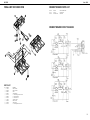
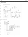
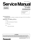
PEDAL UNIT EXPLODED VIEW
CONNECT BOARD PARTS LIST
15229728
15119112
13299199
GP2S24B
2SA1015Y
EVND8AA03B13
PHOTO INTERRUPTER
TRANSISTOR
TRIMMER
2
6
CONNECT BOARD CIRCUIT DIAGRAM
4
1
7
3
11
11
11
11
9
8
5
2
10
PARTS LIST
No.
q
w
e
r
t
y
u
i
o
!0
!1
Parts No.
71018623
00904190
00908023
00904223
40011334
00908034
00677978
71018601
00907045
22285396
40011278
Part Name
PEDAL CENTER
PEDAL CHASSIS
FELT L
COILED SPRING
3 × 12mm Binding Head P-TITE Fe BZC
6 × 35mm JOINT BOLT
6 × 12mm JOINT NUT
CONNECT CORD
PEDAL CABLE
ADJUST BOLT
3 × 8mm Binding Head P-TITE Fe ZC
21
HP-555G
Nov. 1998
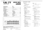
KEYBOARD DISASSEMBLY
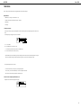
Installing the PA-4A board
Removing PA-4A key
sub-shassis, and screw the board into the sub-shassis.
Screw in order, from the round hole(positioning hole) on the
As shown in Fig.3, place the board against the hook part a of the
While holding the front end of the key, insert the tip of long-nose
pliers into the U-groove on the shaft side(shaded area in Fig.1) and
connector side.
Be sure to screw manually. (Care should be taken to avoid screw
hold down the key in the direction of arrow A.
damage.)
Fig.3
Fig.1
Greasing points
After the key or hammer has been replaced, the specified grease
must be applied to the following 4 points as shown in Fig.4.
Installing the PA-4A key
Fig.4
While placing the front inner wall of the key against the guide, pass
the foot through the hole of the chassis, as shown in Fig.2. Then
press the dotted area of the key in the direction of arrow.
1. Froir GP-1RS....gray (PNo. 17049544)
(a) Key and hammer bearing section
(b) Key and hammer joint section (actuator section)
2. Froir G-336A....white (PNo. 17049543)
(a) Side of guide bushing for white key and black key
1-a
2-a
Fig.2
1-b
Fig.4
22
HP-555G
Nov. 1998
KEYBOARD PARTS LIST
KEYBOARD PA-4A88-C2 CIRCUIT BOARD/
HP-335/535/245/555G·KR-575/575P
Qty.
7/ 1
8/ 1
7/ 1
7/ 1
7/ 1
7/ 1
7/ 1
1/ 1
1/ 1
36/ 1
52/ 1
36/ 1
1/ 1
1/ 1
7/ 1
1/ 1
52/ 1
36/ 1
6
7
8
9
10
11
12
13
14
15
16
22265498
PA-4
CUSHION A
2/ 1
********
00453401
00452145
00564867
01237089
00561890
40011067
40012256
70894556
70894567
70894578
22185247
23475965
23475342
40011267
00347201
00347234
PA-4
CUSHION U ZUREN DBK-2
PA-4A
CUSHION I
PA-4A
CUSHION RZA
PA-4A
CHANNEL
BINDING TAPTITE B 3X8 ZC
BINDING TAPTITE B 3X10 ZC
PA-4A
PWB LOW ASSY
17
PA-4A
PWB MID ASSY
PA-4A
PWB HI ASSY
18
PA-4
RUBBER SWITCH 12P
19
FUJI CARD 14X70-A5.0BB-P1.25-HBL8
20
FUJI CARD 8X60-A5.0BB-P1.25-H8
BINDING TAPTITE P 3X6 ZC
21
FUJI CARD 14X180-A6.0BBR-P1.25-HBL10-S
22
FUJI CARD 16X180-A6.0BBR-P1.25-HBL10-S
23
Item 18 marked * is included in each unit of item 17.
1/
1/
1/
8/
16/
30/
1/
1/
1/
8/
1/
1/
10/
1/
1/
1
1
1
1
1
1
1
1
1
1
1
1
1
1
1
PA4A PWB HI
ASSY 70894578
5
PA4A PWB MID
ASSY 70894567
2
3
4
PA4A PWB LOW
ASSY 70894556
1
*
01019690
01019701
22155784
00019912
PARTS NAME
PA-4A
N-KEY A
PA-4A
N-KEY B
PA-4A
N-KEY C
PA-4A
N-KEY D
PA-4A
N-KEY E
PA-4A
N-KEY F
PA-4A
N-KEY G
PA-4A
N-KEY A'
PA-4A
N-KEY C'
PA-4
S-KEY
PA-4A
N-KEY HAMMER
PA-4A
S-KEY HAMMER
CHASSIS 88P-CK ASSY
PA-4A
PA-4A
CHASSIS 88P
SUB CHASSIS A
PA-4A
PA-4A
SUB CHASSIS B
PA-4
GUIDE BUSHING A
PA-4
GUIDE BUSHING S-KEY
PARTS No.
00455501
00455512
00455534
00455545
00455556
00455578
00455589
00458689
00458690
32575291
00458178
00458189
No.
View from components side.
PA-4A88-C2 KEYBOARD ASSY PARTS LIST
71017401
23
HP-555G
Nov. 1998
KEYBOARD PA-4A88-C2 CIRCUIT DIAGRAM
24
HP-555G
A
B
C
D
E
F
G
H
I
J
K
L
M
N
O
P
Q
R
S
T
U
V
Nov. 1998
BLOCK DIAGRAM
25
HP-555G
A
B
C
D
E
F
G
H
I
J
K
L
M
N
O
P
Q
R
S
T
U
V
Nov. 1998
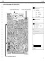
CIRCUIT BOARD (MAIN)
ASSY 71012690
View from components side.
View from foil side.
26
HP-555G
A
B
C
D
E
F
G
H
I
J
K
L
M
N
O
P
Q
R
S
T
U
V
Nov. 1998
CIRCUIT DIAGRAM (MAIN)
27
HP-555G
A
B
C
D
E
F
G
H
I
J
K
L
M
N
O
P
Q
R
S
T
U
V
Nov. 1998
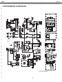
CIRCUIT BOARD (PANEL L)
ASSY 71012712
NOTE
PANEL L BOARD ASSY includes the following parts.
01450034
01450045
01450023
12X400-P2.0-51065-51015-F
8X400-P2.0-51065-51015-F
9X350-P2.0-51065-51015-F
View from components side.
28
WIRING
WIRING
WIRING
HP-555G
A CIRCUIT BOARD (PANEL R)
ASSY 71012723
B
C
D
E
F
G
H
I
J
K
L
M
N
O
P
Q
R
S
T
U
V
Nov. 1998
NOTE
PANEL R BOARD ASSY includes the following parts.
01452712
01452734
01452723
10X100-P2.0-51065-51015-F
14X350-P2.0-51065-51015-F
15X400-P2.0-51065-51015-F
WIRING
WIRING
WIRING
View from components side.
29
HP-555G
Nov. 1998
A CIRCUIT DIAGRAM (PANEL L / PANEL R)
B
C
D
E
F
G
H
I
J
K
L
M
N
O
P
Q
R
S
T
U
V
30
HP-555G
A
B
C
D
E
F
G
H
I
J
K
L
M
N
O
P
Q
R
S
T
U
V
Nov. 1998
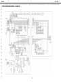
CIRCUIT BOARD (FRONT JACK, ANALOG ,INLET)
NOTE
PAB3 ANALOG PHANTOM includes the following parts.
71011878 PAB3 INLET 100/117V
71011867 FRONT JACK BOARD
********
********
PAB3 EQ BOARD ASSY
PAB3 ANALOG BOARD
NOTE : PAB3 ANALOG BOARD includes the following parts.
22195975
22195973
01349990
01349978
01349912
01346423
01346412
TR HOLDER
POWER AMP HOLDER
WIRING W4
7 x 250-P2.0-PH-SAN-F
12 x 130-P2.0-PH-SAN-F
HEATSINK
PAB HOLDER
NOTE
PAB3 FRONT JACK BOARD includes the following parts.
01344545
JACK HOLDER
NOTE
PAB3 INLET 100/117V includes the following parts.
23425740
12559444
00129367
INL-8 10A/125V 2P PO
5x20 SB 4 4A/125V
INLET HOLDER
AC INLET
FUSE
Replacemant INLET BOARD PAB3 INLET ASSY is for 100/117V version exclusive use.
When using PAB3 INLET ASSY for 230/240V version, be sure to make the following
modifications.
1. INLET BOARD FOR 100/117V version differs from 230V version in FUSE system.
Replace fuse (F1 on INLET BOARD) to specific one. (#12559550 FUSE 5x20 S506
1.6A T1.6AL250V for 230V version) See TABLE A.
2. For safety standards, place fuse seal (#40013712 FUSE SEAL T1.6AL250V #407) at the
proper place of the INLET BOARD. The location of fuse seal is over the following
printing (see fig A) of the PWB. When necessary, please order fuse seal separatery from
INLET BOARD.
TABLE A
100V/117V
230V/240V
FUSE 5 x 20 SB 4 4A/125V
FUSE 5 x 20 S506 1.6A T1.6AL250V
Fig.A
3.15A/125V
View from components side.
71121767 PAB3 ANALOG PHANTOM
31
HP-555G
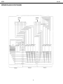
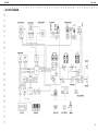
CIRCUIT DIAGRAM (FRONT JACK, ANALOG ,INLET)
HP-535/555G
EQ BOARD
2
1
3
6
7
Pedal
C47
33/16
6
C43
0.01
1
4
7 -
R39
330
3
+
8
+
IC8B
UPC4570HA
8
2
1
2
1
5
SSSF124
SW301B
IC301D TC74HC00AF
12
11
13
R324
3.3K
25
24
23
22
L305
ELDR25V
C304
0.01
+
L301
R312
150
C303
0.1
R328
10K
+
+
R327
10K
IC303
+
16
3
5
4
15
12
9
8
+
R313
6.8K
ELDR25V
IC301E
TC74HC00AF
+
+
R320
1K
R314
33
R325
12K
2
1
6
7
14
13
10
11
L309
L310
L311
L308
M5M34051P
R326
5.6K
L306
L307
ELDR25V
R318
4.7K
D304
MTZJ27C
D303
MTZJ27C
(CN10)
PIANO ANALOG BOARD
32
R317
10K
R329
5.6K
D306
MTZJ27C
Computer
Switch
SSSF124
TCS7927-28-401 JK304
7
8
5
2
4
1
3
6
R323
12K
2
IC8A
UPC4570HA
26
21
SSSF124
SW301A
15
14
16
13
11
12
C306
33/16
C305
1000P
F
CN7
WIRING 01349978
TO MAIN BOARD
R322
33
1
TRANS BOARD
2
IC7A
UPC4570HA
MIDI In
(FRONT)
M1756
20
D305
MTZJ27C
2 2
+
C42
0.01
R33
680K
JK303
5
2
4
R315
120
D307
MTZJ27C
D308
MTZJ27C
1
4
-
R32
680K
YKB21-5006
D302
1SS133
10 SW301C
1
F
R31
680K
6 +
IC7B
UPC4570HA
3
R38
330
8
3
2 2
C9
330/6.3
C41
0.01
WIRING 01349990
CN501
1
2
3
4
5
2
D14
S5688G
7 -
Phones
9
2
D
R37
330
1
12
2
33
44
55
66
77
8 89
9
10
10
2
1
4
4
1
1
JK301
2
D
1
1
2
2
33
44
55
66
77
88
9
9
5
4
2
3
7
8
1
1
- 12
2
6
IC301C
TC74HC00AF
1
IC7C
10
5
2
+
R319
100
7
R311
3.3K
10
8
IC301A
TC74HC00AF
R321
150
14
1
9
14
7
YKF51-5031
4
1
1
5
2
1
8
2
1
9
1
2
1
2
1
D
C50
33/16
To
MAIN
BOARD
(CN9)
IC11G
HD74LS04P
JK5
68
R307
YKB21-5006
5
4
2
3
7
8
1
PC-910
1
TER1
MEP1866-A
D
D +5
C62
0.1
1
(REAR)
CN302
B9B-PH-K-S
R50
100
33
R303
IC302
4
2 2
4
3
3
IC10
PC-910
15
12
14
R306
68
+
R316
1K
3
D18
1SS133
R58
150
To
PAB3
ANALOG
BOARD
(CN2)
D +5
D
1
2
+
3
2
C12
0.068
6
+
1
IC2
12
2
Power
Indicator
D301
1
JK302
R309
68
R305
33
6
2
R62
120
1
12
23
34
4
55
66
77
C18
0.068
+
D
1
C22
6800/16
OUT
13
C302
0.01
Q301
+
RN2227
3
MIDI
7
- 12
C35
330/16
1
IN
2
1
2
- 12
UPC24A05HF
1
+1
~
AN79M12F
2
S5688G
S5688G
2
1
2 COM
3
D1
D3SBA20
R69
150
D9
S5688G
-
1
2
3
4
5
D3
~
2
2 COM
COM 1
1
D4
4 -
IC8C
OUT 3
IC3
-
IC1C
10
C301
33/16
R310
68
33
R308
L304
L303
L302
IC301B
TC74HC00AF
5
1
2
1
2 IN
C25
0.068
UPC4570HA
-
D13
S5688G
C27
0.068
C26
0.068
C49
33/16
11
8
8
D
D +5
8
~
C34
0.068
+ 12
M5218AL
2
25
22
24
4
OUT 3
D10
S5688G
FH2
CNT47-0003A
R72
150
UPC4570HA
1
+
R302
150
IN
1 IN
2
C40
330/16
+ 12
AN78M12F
R57
150
R304
33
ELDR25V
YKF51-5048
JK6
220
R70
1K
IC11D
HD74LS04P
IC11A
HD74LS04P
IC11E
HD74LS04P
IC11F
HD74LS04P
3
R75
6
IC11B
HD74LS04P
R41
33K
8
B8B-PH-K-S
5
3
A
XRST
IC11C
HD74LS04P
4
5
Q14
RN2227
R71
220
2
R65
10K
R2
330(1/2W)
D +5
R74
3.3K
680
R301
L-1384AD/1ID
CN301
B8B-PH-K-S
88
7
76
6
5
5
4
4
3
32
2
1
1
- 12
3
9
To
CN1
PAB3
ANALOG
BOARD
MS
2
1
1
R30
6.8K
+
2
+
D +5
- 12 Q4
2SA1015GR
To
PAB3
PHONES
BOARD
(CN301)
8
IC1B
M5218AL
CN1
88
77
66
5
5
4
4
3
3
2
2
1
1
D
R34
3.3K
Q5
2SC1815GR
CN401
B2P5-VH
ASSY 71011867
5
2
2
D12
1SS133
1
2
3
- 12
S5688G
1
A
A
1
7
R13
680K
A
+ 12
A
D +5
9
R20
680K
+
C401
4700
To
TRANS
PRIMARY
FRONT JACK BOARD
2
5
680K
-
+ 12
2SK363GR
Q7
R9
68
1
3
R21
6
2
A C14
ECQV1H 0.33
Q18
2SC1815GR
HLJ7101-01-3010
R7
1K
- 12 Q3
A
2SA1015GR
CNT47-0003A
FH401
7
3
11
22
33
44
55
R
R1
A
IC5
2
A
To
POWER
SWITCH
B2P3-VH
F1
C65
0.01
330(1/2W)
F1
100/117V SB 4A/125V FUSE (ASSY 71011878)
230/240V S506 1.6A/250V FUSE (ASSY 71015456)
2
2
3
R12
15K
C20
ECQV1H 0.33
- 12
R85
6.8K
F
A
Q15
2SA1015GR
1
1
1 1
1
1
IC1A
M5218AL
1
3
R8
68
3
680K
A
A
A
JK401
1
2
CNT47-0003A
FH402
330P
Q2
2SC1815GR
3
2
- 12
R42
6.8K
Inlet
INL-8
2
4
1
4
A
1
2
A
D +5
D11
C5
4700p
1
1
2
A
To
PAB3
ANALOG
BOARD
CN15
CN201
10JQ-ST
CN402
1
1
2
2
3
3
L(MONO)
Output
C8
330P
C202
33/16
IC202C
INLET BOARD
JK1
HLJ7101-01-3010
JK2
330
C7
+
NE5532
OUT
R103
6.8K
R25
6.8K
- 12
R67
150K
+
C214
0.33
R216
6.8K
C211
0.082
-
+
IC201C
3
+ 12
C207
0.082
F
A
R15
6.8K
3
6800/35
C39
A
R16
2
Q20
RN2227
A
A
2
3
C2
330P
2
4
1
1
C63
33/16
1
MC
C52
0.068
6
13
9
3
6
8
12
14
A
2SC2878A
R17
680
R14
2SK363GR
Q6
R211
6.8K
5 2 4
1
2
2
33/16
R10
680K
A
1
D21
MTZJ9.1B
2
~
+
3
1
R3
3.3K
R5
6.8K
C3
330P
5
A
0.068
CNT47-0003A
3
8
1
9
1
2
A
3
Q12
Q13
2SC1815GR
D20
MTZJ9.1B
2
1 2
1
3
A R79
150
1
D24
1SS133
2SK363GR
Q19
2-
R19
680K
2
1
2
D23
1SS133
3
ECQV1H 0.33
C19
ECQV1H 0.33
Q10
R61
68K
R78
150
R95
6.8K
1
3
C48
F5
7
IC4B
M5218AL
R18
C13
2
2SC1815GR
R68
33K
2
1
C72
3.3/50
R66
15K
A
A
2
R40
6.8K
6800/35
FH1
A
C21
3
R11
15K
R24
6.8K
D +5
C51
R6
330
Q1
3.3K
R56
6.8K
2
D22
1SS133
2
1
FH4
+
C6
0.1
2SA1015GR
2
D15
CNT47-0003A
CNT47-0003A
5
NE5532
C58
0.068
33/16
C4
0.068
R205
6.8K
R219
680K
IC202B
NE5532
7
5
6
C203
0.068
- 12
4
F3
8
IC9B
UPC4570HA
C61
0.068
3
1
4
3
D16
D5SBA20
D3SBA20
2
R201
6.8K
C205
0.068
2
FH6
6-
2
68K
R51
4
B5P-VH
6+
1
6
- 12
R4
680
C15
1
IC4A
M5218AL
R209
6.8K
7
To
SPEAKER
TERMINAL
A
C54
33P
5.6K
75.6K
+
IC9A
UPC4570HA
A
FH8
CNT47-0003A
C44
4700p
3
IC201B
NE5532
5
B8P-VH
A
C56
0.068
A
1 1
2SK363GR
Q11
1
+
F4
2-
RL1C
R213
6.8K
R206
6.8K
R202
6.8K
C201
33/16
R97
680
5.6K
2
1
1
2
32
43
4
55
66
77
88
R64
6.8
R92
56K
1
R
R220
680K
R214
6.8K
16
4
C80
33/16
2
R210
6.8K
R80
15K
A
A
IC201A
NE5532
R207
6.8K
C215
0.33
1
IC202A
NE5532
1
C66
A
3.3/50
Q8
2SC2878A
TER2
MEP1866-A
FH7
+
A
F
CNT47-0003A
2
A
D6
1SS133
MTZJ9.1B
1
1
2
23
3
4
4
5
5
C76
680P
R84
56K
L
5
1
1
D17
CN2
-
A
C46
33/16
5 IC12B
STK401-070
A
- 12
R48
8
C81
3.3/50
1
R101
6.8K
R108
6.8K
R45
PAB3 ANALOG BOARD
FUSE
F3/F4 SB 5A/125V
F5 SB 4A/125V
1
2
3
2
4
IC6B
UPC4570HA
2
3 +
Q17
2
F
2
R98
680
A
2
4
2
A
A
3
2
1
CN9
RL1B
R217
6.8K
2 -
C208
0.082
R212
6.8K
23+
R203
6.8K
G5Z-2A-12V
RL1A 3
2
+
1
D19
S5688G
C55
0.068
A
2SB647
56K
2
6
A
R96
680
A
2
C57
0.068
7
10
11
5
2
1
7-
R63
6.8
R91
R47
R43
5.6K
2
R36
12K
D8
1SS133
A
C45
33/16
1
C60
0.068
R54
6.8K
C53
33P
A
15
R109
6.8K
C85
33/16
1
+
IC6A
UPC4570HA
A
1
2
C59
0.068
-
C38
33P
A
1
A
1
A
12K
2
C23
0.1
2
2
C28
0.068
- 12
+ 12
IC9C
R53
6.8K
+
R29
2
A
HLJ7101-01-3010
R35
A
C83
33/16
1
2
UPC4570HA
R99
6.8K
2
R28
33K
C31
330P
JK4
4
A
C30
33/16
1
R27
330
2
4
1
3D5
D7
1SS133
C36
33P
12K
2
R23
33K
A
A
R
1SS133
1
C17
330P
Input
R26
12K
2
C84
33/16
1
2
R100
6.8K
A
- 12
C16
33/16
1
R22
330
R55
6.8K
C70
A
A
C37
0.068
M51953BL
D
JK3
HLJ7101-01-3010
2
4
1
R88
33K
+
1
A
4
2
-
G
NC
C77
1/50
1
C33
0.068
1
9
5
DLY 4
3
2
IC6C
IC13
RST
1 VCC
2
C87
33/16
To
PAB3
TRANS
BOARD
(CN501)
+
5
D
C75
680P
C79
33/16
ECQV1H 0.33
A
1
1
1
D
DTC124ES
R89
33K
+ 12
UPC4570HA
R117
D +5 3.3K
Q22
R83
56K
C86
33/16
C29
0.068
IC4C
1
3
G5Z-2A-12V
1 IC12A
STK401-070
- 12
+ 12
M5218AL
2
2
3
+
DD 5
1
21
2
33
44
55
66
77
88
99
10
10
1
1
22
33
44
55
66
1
1
22
33
44
55
66
77
88
1
2
1
12
2
33
44
B4B-PH-K-S
L(MONO)
C93
33/16
ECQV1H 0.33
R52
C71
6.8K
XRST
C88
3.3/50
1
2
- 12
Q21
DTC124ES
2
R208
6.8K
C204
0.068
R204
6.8K
A
1
Q16
2SD667
F
R110
680
R105
6.8K
- 12
R121
3.3K
CN4
To FDD UNIT
2
D +5
R123
3.3K
3
CN16
WIRING 01349912
F
2
A
+ 12
1
D + 5 Q23
RN2227
+
DD 5
2
To
MAIN
BOARD
(CN11)
R115
6.8K
C91
33/16
1
TER4
M1698
4
3
C89
33/16
R116
6.8K
R119
6.8K
F
1
2
1
12
12
11
11 10
10 9
9
88
7
7
66
55
4
4
33
2
21
1
+ 12
2
MC
F
TER3
M1698
+ 12
2
A
R120
6.8K
B10B-XH-A
CN15
4
3
C212
0.082
1
-
C92
33/16
1
MS
1
2
C64
3.3/50
2
R76
15K
+
53253-0610
CN11
53253-0810
CN13
+
ASSY 71011978
C206
0.068
-
To
MIC
BOARD
(CN1)
+
To
PANEL L
BOARD
(CN1)
To
PAB3
EQUALIZER
BOARD
(CN201)
5
A
B
C
D
E
F
G
H
I
J
K
L
M
N
O
P
Q
R
S
T
U
V
Nov. 1998
Computer
HP-555G
A
B
C
D
E
F
G
H
I
J
K
L
M
N
O
P
Q
R
S
T
U
V
Nov. 1998
CIRCUIT BOARD (MIC)
ASSY 71011901
NOTE
MIC BOARD ASSY includes the following parts.
22150756
01344489
JACK NUT 2
MIC HOLDER
View from components side.
CIRCUIT BOARD (LCD B)
ASSY 71012167
View from components side.
33
HP-555G
Nov. 1998
A CIRCUIT DIAGRAM (MIC)
B
C
D
E
F
G
H
I
J
K
L CIRCUIT DIAGRAM (LCD B)
M
N
O
P
Q
R
S
T
U
V
34