1
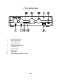
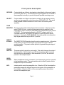
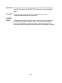
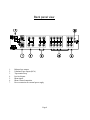
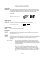
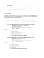
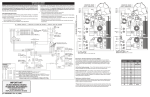
Table of contents
Safety precautions
page 3
Introduction
page 4
Front panel view
page 5
Front panel description
page 6
Record
page 6
Select
page 6
Tape Monitor
page 6
Direct Bypass
page 6
Power Switch (Mute)
page 6
Headphone
page 6
LED
page 6
Balance
page 7
Volume
page 7
Stereo/Mono
page 7
Back panel view
page 8
Back panel description
page 9
Balanced Preouts
page 9
Page 1
Unbalanced Preouts
Tape Monitor Loop
page 9
page 9
Line Level Inputs
page 9
Phono Inputs
page 9
Phono Ground
page 10
Power Connection
page 10
Phono Stage Configuration
page 10
MM/MC selection
page 10
Capacitive Loading
page 10
Resistive Loading
page 11
Tables
page 12
Block diagram
page 13
Making the connection
page 14
Troubleshooting
page 15
Specifications
page 16
Warranty
page 17
Accessories Included : Power cord, Power supply, Owners Manual
Page 2
SAFETY PRECAUTIONS
PLEASE READ BEFORE INSTALLING
•
Turn preamplifier ‘off’ when plugging in or unplugging input and speaker
cables!!!
•
When plugging in or unplugging interconnect cables running from
source to preamplifier, always mute the preamplifier and rotate the
preamplifiers volume control to minimum first. It is recommended that
you turn the amplifier ‘off’ as well for this operation.
•
The PRO10 is equipped with raised feet so that continuous ventilation
can be maintained. They help to maintain acoustic feedback into the
amplifier at a minimum. They also provide a measure of protection
against scratching any surface the unit might be resting on. Do not
alter or remove them.
•
Do not stack anything on top of the preamplifier (processor,
source...etc.).
Page 3
Introduction
Thank you for selecting B&K Components, Ltd.’s PRO10 preamplifier. The PRO10 is
designed for the discriminating audiophile. The PRO10 is a DC coupled preamplifier that
has been designed using all discrete circuit topology with a switchable head amp on the
phono stage. Gold-plated premium connectors have also been utilized to minimize
degradation in the signal path. The PRO10 has an external power supply that should be
connected to an unswitched AC source. In order to obtain maximum performance from this
unit, Please read these instructions very carefully.
Features
FET loading - Maximizes linearity and minimize noise.
Wide bandwidth - Assure clear reproduction with all styles of music.
Polypropylene
film capacitors - RIAA accuracy typically within ± .2 dB through the use of polypropylene
film capacitors. This produces a transparent sound with highly accurate musical timbre.
Volume control - From a single precision attenuator. Accuracy of volume attenuation is
within .1 dB from channel to channel.
1% Metal Film resistors - Low noise resistors for better sound and a greater degree of
repeatability.
Also: Direct output capability
All discrete predriver circuitry
Premium gold-plated connectors
Separate source and record selectors
Balanced outputs standard
Page 4
Front panel view
1.
2.
3.
4.
5.
6.
7.
8.
9.
10.
Record selector knob
Source selector knob
Tape monitor button
Direct bypass button
Power switch (mute switch)
Headphone jack
Power on LED
Balance knob
Volume knob
Mono/Stereo selector button
Page 5
Front panel description
RECORD - Controls which one of the six input pairs is routed directly to the record output
connectors (REC OUT). The selected input signal bypasses the remainder of
the preamplifier’s circuitry to provide the purest possible recording source.
SELECT -
Controls which one of the six input pairs is routed to the processing circuitry
and then to the preamplifier output connectors (PRE AMP OUT). The signal
made available at these connectors is used to drive the external power
amplifiers.
TAPE
MONITOR - The tape monitor switch allows the tape deck connected to the tape monitor
inputs (TMON IN) to be routed to the processing circuitry and then to the
preamplifier’s output connectors (PRE AMP OUT) independent of the position
of SELECT. The input signal selected via SELECT remains valid but is
overridden while the TAPE MONITOR switch is in the ON position (switch
pushed in). Turning the TAPE MONITOR off (switch pushed out) restores the
input signal determined by the SELECT position.
DIRECT
BYPASS -
POWER
SWITCH -
HEADPHONE -
LED -
The DIRECT BYPASS switch selects the active or passive mode. In the active
mode (switch out) the selected signal is processed through a 20 dB DC
coupled amplifier. The passive mode (switch in) bypasses the gain stage of
the preamplifier.
The power switch is actually a mute switch. This switch changes the mode of
the preamplifier. With the switch on, LED illuminated, the signal is passed
from the source to the amplifier. With the switch off, LED off, the source is
passed to the headphone jack.
Stereo headphones having a standard ¼ inch binaural plug can be connected
to the headphone output. The mute switch must be in the off position for the
headphone output to be enabled.
Indicates which mode the preamplifier is in. When the LED is illuminated the
preamplifier passes the selected source to the outputs of the preamplifier to
the amplifiers. When the LED is off the preamplifier passes the selected
source to the headphone jack.
Page 6
BALANCE - The balance control is used to adjust the relative volume of the left and right
channels. This affects the PRE AMP OUT connections and the headphone
output.
VOLUME -
STEREO
MONO -
Turning the volume control clockwise increases the volume level,
counterclockwise decreases the volume level.
The stereo/mono switch selects the mode in which the incoming signals are
processed through the preamplifier. Stereo mode (switch out) provides
normal stereo reproduction, monaural signals will be reproduced in mono.
Mono mode (switch in) reproduces both stereo and mono signals in monaural.
Page 7
Back panel view
1.
2.
3.
4.
5.
6.
7.
Balanced pre-outputs
Unbalanced pre-outputs (RCA)
Tape monitor loop
Line level inputs
Phono inputs
Phono Ground connection
Power connection for external power supply
Page 8
Back panel description
BALANCED
PREOUTS - For use with balanced output cables when your amplifier has balanced inputs.
The balanced outputs will help improve the quality of sound being reproduced
by the amplifier when there is a long run between the amplifier and the
preamplifier.
Balanced connector cable end
UNBALANCED
PREOUTS - Standard RCA outputs to connect patch cables to amplifiers.
RCA connector cable end
TAPE MONITOR
LOOP For connection of your tape recorder.
LINE LEVEL
INPUTS Line level inputs are for connecting your source components to the system.
(CD, Tape, Tuner,... etc.)
PHONO
INPUTS -
Phone inputs are for the connection of a turntable. These inputs are switchable
which allows them to be configured for a moving magnet or moving coil
cartridge.
Phono stage -
The phono stage of the PRO10 may be configured for either
Moving Magnet (MM) or Moving Coil (MC) applications with the
additional capability to set the resistive and capacitive loading of
the phono cartridge.
NOTE: Your PRO10 has already been configured for a MM
stage with a resistive loading of 50 Kohms and you need not
perform any modifications unless you so desire. To reconfigure
your PRO10, follow the appropriate procedure listed on page
10.
Page 9
PHONO
GROUND - For connection of your ground wire for phono use.
POWER
CONNECTION - For connection of the included power supply. **
Caution must be taken when connecting the included power supply. Do
not force the plug as you may damage the pins inside the preamplifier.
The plug is keyed so you can only insert it in one orientation.
**NOTE - USE ONLY B&K COMPONENTS POWER SUPPLY.
Phono Stage Configuring
Select Moving Magnet (MM) or Moving Coil (MC)
1.
Locate the 2 position push button switch on the inside of the unit (see figure 1). It is located near
the back left side. The switch can be identified by a metal tab at the end which indicates whether
MM or MC is selected.
2.
Push the switch in to select the type of phono stage that is desired (MM/MC). The switch
“toggles” the selected stage between MM and MC each time the switch is depressed.
NOTE: The PRO10 is shipped from the factory with the phono stage set to the MM configuration and a
resistive loading of 50 Kohms. Selecting the MC stage without changing the resistive loading will result in
an effective load of 133 ohms.
Capacitive Loading
NOTE: The PRO10 is shipped from the factory with no capacitor installed. Typically, the
capacitance of the phono cables (C phono cables ) is sufficient and no capacitor is needed.
1.
2.
Determine the capacitor value (pF) for proper loading of the MM cartridge in accordance with
the specifications of the cartridge you have selected. A recommended value may be suggested by
the manufacturer of the cartridge. The capacitive loading affects both the MM and MC stage.
The capacitance (C load) should be:
Cload = C cartridge - Cphono cables - 75 pF
Locate the 2 gold-plated pin receptacles with the label “CLOAD” between them on the inside of
the unit (see figure 1). They are located near the left end of the circuit board. Near the MM/MC
Page 10
selector switch.
3.
Trim the leads of the capacitors (one required per channel) to approximately _ inch.
4.
Insert the leads into the CLOAD pin receptacles securely.
Resistive Loading
NOTE: The PRO10 is shipped from the factory with a 100 Kohm resistor installed and the phono stage
MM configuration selected. This resistor should not be removed unless the resistive loading is being
changed in accordance with the following guidelines.
1.
Determine the resistor value for proper loading of the cartridge in accordance with the
specifications of the cartridge you have selected. A recommended value may be suggested by the
manufacturer of the cartridge. The resistive loading affects both the MM and MC stage.
The resistive loading for the MM stage can be calculated using the following equation:
Ri (in Kohms) = (100,000 * Rc) / (100,000 - Rc)
Ri = inserted resistor value
Rc = cartridge loading value (must not exceed 100Kohms)
Kohms = 1,000 ohms
example:
Rc (desired) = 50 Kohms
Ri = (100,000 * Rc) / (100,000 - Rc)
Ri = (100,000 * 50,000) / (100,000 - 50,000)
Ri = (5,000,000,000) / (50,000)
Ri = 100,000 ohms = 100 K ohms (factory installed)
The resistive loading for the MC stage can be calculated using the following equation:
Ri (in ohms) = (133 * Rc) / (133 - Rc)
Ri = inserted resistor value
Rc = cartridge loading value (must not exceed 133 ohms)
For Ri >> 1300, Rc = 133 ohms
example:
Rc (desired) = 100 ohms
Ri = (133 * Rc) / (133 - Rc)
Ri = (133 * 100) / (133 - 100)
Ri = (13,300) / (33)
Ri = 403 ohms (use 402 ohm standard value resistor)
Page 11
NOTE: You may not be able to attain the proper value resistor to fit you application, use the closest
standard value you can find.
Refer to the following table for more calculated values of MM
Rc desired
(ohms)
5K
20 K
35 K
50 K
75 K
Ri calculated
(ohms)
Ri standard
(ohms)
5.3 K
25.0 K
53.8 K
100 K
300 K
5.36 K
24.9K
53.6 K
100 K
301 K
Refer to the following table for more calculated values of MC
Rc desired
(ohms)
25
45
75
100
125
Ri calculated
(ohms)
Ri standard
(ohms)
30
68
171
403
2.1K
30.1
68.1
169
402
2.10K
2.
Locate the 2 gold-plated pin receptacles with the label “RLOAD” between them on the inside of
the unit (see figure 1). They are located near the left end of the circuit board and near the
MM/MC selector switch.
3.
Trim the leads of the resistors (one per channel) to approximately _ inch.
4.
Insert the leads into the RLOAD pin receptacles securely.
5.
The factory installed resistors in the PRO10 will match most phono cartridges on the market.
Page 12
Figure 1
Block Diagram
Page 13
Page 14
Making the connection
The diagram below shows a typical connection between the preamplifier and a B&K
amplifier using the unbalanced RCA outputs.
Note: The balanced button on the amplifier must be in the off (out) position.
The diagram below shows a typical connection between the preamplifier and a B&K
amplifier using the balanced XLR outputs.
Note: The balanced button on the amplifier must be in the on (in) position.
You may use either of these options to connect your preamplifier to the main amplifier. If you
wish to connect additional amplifiers, you may use both examples or use both sets of PREAMP OUTS.
Page 15
Page 16
PRO10 Specifications
Moving Coil Sensitivity (at 1kHz)
.09 mV
Moving Coil Overload (at 1kHz)
17 mV
Moving Coil Load Resistance
Variable
Moving Coil Load Capacitance
Variable
Moving Coil (S/N A Weighted)
70 dB
Moving Magnet Sensitivity (at 1kHz)
.8 mV
Moving Magnet Overload (at 1kHz)
225 mV
Moving Magnet Load Resistance
Variable
Moving Magnet Load Capacitance
Variable
Moving Magnet (S/N A Weighted)
82 dB
THD
.02 %
IM Distortion (SMPTE)
.02 %
Frequency Response (± 1 dB)
1 Hz - 150 kHz
High Level Sensitivity
45 mV
Maximum Output
14 V R.M.S.
High Level (S/N A Weighted)
89 dB
Processor Loops
1
Page 17
Limited Warranty
B&K Components Ltd., referred to herein as B&K, warrants your B&K equipment against all defects in
material and workmanship for a period of five years from the date of purchase. This warranty applies only to
the original purchaser and only to equipment in normal residential use and service. Defective equipment must
be returned to B&K, prepaid, accompanied by sufficient payment to cover the cost of return shipping and
handling, and will be repaired or replaced at the discretion of B&K whose decision as to the method of
reparation will be final.
This warranty shall not apply to any equipment which is found to have been improperly installed, incorrectly
fused, misused, abused, or subjected to harmful elements, used in any way not in accordance with
instructions supplied with the unit, or to have been modified, repaired or altered in any way without the
expressed, written consent of B&K. This warranty does not apply to the cabinet, the remote controller, or
appearance items such as the faceplate, control buttons, or display lenses, nor does it cover any expenses
incurred in shipping the unit to and from the manufacturer’s service depot.
No warranty, implied or otherwise created by State law shall extend beyond the terms of this warranty and
B&K shall not be liable for any incidental or consequential damage arising out of a defect in material or
workmanship of the unit during the terms of this warranty or thereafter. Some States do not allow the
exclusion or limitation of incidental or consequential damages and the foregoing exclusions may not apply to
you.
This warranty gives you specific legal rights. Your may also have other rights which vary from State to State.
No agent, representative, dealer or employee of B&K has the authority to increase or alter the obligations or
terms of this warranty.
B&K Components Ltd.
RETURNING EQUIPMENT
No equipment may be returned to B&K Components Ltd. Without a RETURN AUTHORIZATION. Should you
find it necessary to return equipment to B&K, for any reason, a RETURN AUTHORIZATION (R.A.) number
must be issued by B&K in respect of the equipment being returned. You may request an R.A. number by
calling B&K at the numbers below. We ask that you provide the following information at that time.
1.
2.
3.
Your name, address, and phone number.
The model and serial number of the equipment being returned.
A description of the problem being experienced.
Your call will be referred to a Technical Service Representative who will work with you to resolve the problem.
If it is determined that the unit must be returned for repair, an R.A. number will be issued.
Customer service hours are 10:00am to 12:00pm and 1:00pm to 4:00pm.
B&K Components Ltd. 2100 Old Union Road, Buffalo New York 14227
1-800-543-5252 or 1-716-656-0023
Page 18